EP4478517A1 - Separator for electrochemical devices and method for manufacturing same separator - Google Patents
Separator for electrochemical devices and method for manufacturing same separator Download PDFInfo
- Publication number
- EP4478517A1 EP4478517A1 EP23835879.0A EP23835879A EP4478517A1 EP 4478517 A1 EP4478517 A1 EP 4478517A1 EP 23835879 A EP23835879 A EP 23835879A EP 4478517 A1 EP4478517 A1 EP 4478517A1
- Authority
- EP
- European Patent Office
- Prior art keywords
- separator
- spinning solution
- negative electrode
- inorganic particles
- silicon
- Prior art date
- Legal status (The legal status is an assumption and is not a legal conclusion. Google has not performed a legal analysis and makes no representation as to the accuracy of the status listed.)
- Pending
Links
Images

Classifications
-
- B—PERFORMING OPERATIONS; TRANSPORTING
- B32—LAYERED PRODUCTS
- B32B—LAYERED PRODUCTS, i.e. PRODUCTS BUILT-UP OF STRATA OF FLAT OR NON-FLAT, e.g. CELLULAR OR HONEYCOMB, FORM
- B32B27/00—Layered products comprising a layer of synthetic resin
- B32B27/06—Layered products comprising a layer of synthetic resin as the main or only constituent of a layer, which is next to another layer of the same or of a different material
- B32B27/08—Layered products comprising a layer of synthetic resin as the main or only constituent of a layer, which is next to another layer of the same or of a different material of synthetic resin
-
- B—PERFORMING OPERATIONS; TRANSPORTING
- B32—LAYERED PRODUCTS
- B32B—LAYERED PRODUCTS, i.e. PRODUCTS BUILT-UP OF STRATA OF FLAT OR NON-FLAT, e.g. CELLULAR OR HONEYCOMB, FORM
- B32B27/00—Layered products comprising a layer of synthetic resin
- B32B27/18—Layered products comprising a layer of synthetic resin characterised by the use of special additives
-
- B—PERFORMING OPERATIONS; TRANSPORTING
- B32—LAYERED PRODUCTS
- B32B—LAYERED PRODUCTS, i.e. PRODUCTS BUILT-UP OF STRATA OF FLAT OR NON-FLAT, e.g. CELLULAR OR HONEYCOMB, FORM
- B32B27/00—Layered products comprising a layer of synthetic resin
- B32B27/28—Layered products comprising a layer of synthetic resin comprising synthetic resins not wholly covered by any one of the sub-groups B32B27/30 - B32B27/42
- B32B27/281—Layered products comprising a layer of synthetic resin comprising synthetic resins not wholly covered by any one of the sub-groups B32B27/30 - B32B27/42 comprising polyimides
-
- B—PERFORMING OPERATIONS; TRANSPORTING
- B32—LAYERED PRODUCTS
- B32B—LAYERED PRODUCTS, i.e. PRODUCTS BUILT-UP OF STRATA OF FLAT OR NON-FLAT, e.g. CELLULAR OR HONEYCOMB, FORM
- B32B27/00—Layered products comprising a layer of synthetic resin
- B32B27/28—Layered products comprising a layer of synthetic resin comprising synthetic resins not wholly covered by any one of the sub-groups B32B27/30 - B32B27/42
- B32B27/285—Layered products comprising a layer of synthetic resin comprising synthetic resins not wholly covered by any one of the sub-groups B32B27/30 - B32B27/42 comprising polyethers
-
- B—PERFORMING OPERATIONS; TRANSPORTING
- B32—LAYERED PRODUCTS
- B32B—LAYERED PRODUCTS, i.e. PRODUCTS BUILT-UP OF STRATA OF FLAT OR NON-FLAT, e.g. CELLULAR OR HONEYCOMB, FORM
- B32B27/00—Layered products comprising a layer of synthetic resin
- B32B27/30—Layered products comprising a layer of synthetic resin comprising vinyl (co)polymers; comprising acrylic (co)polymers
- B32B27/302—Layered products comprising a layer of synthetic resin comprising vinyl (co)polymers; comprising acrylic (co)polymers comprising aromatic vinyl (co)polymers, e.g. styrenic (co)polymers
-
- B—PERFORMING OPERATIONS; TRANSPORTING
- B32—LAYERED PRODUCTS
- B32B—LAYERED PRODUCTS, i.e. PRODUCTS BUILT-UP OF STRATA OF FLAT OR NON-FLAT, e.g. CELLULAR OR HONEYCOMB, FORM
- B32B27/00—Layered products comprising a layer of synthetic resin
- B32B27/30—Layered products comprising a layer of synthetic resin comprising vinyl (co)polymers; comprising acrylic (co)polymers
- B32B27/306—Layered products comprising a layer of synthetic resin comprising vinyl (co)polymers; comprising acrylic (co)polymers comprising vinyl acetate or vinyl alcohol (co)polymers
-
- B—PERFORMING OPERATIONS; TRANSPORTING
- B32—LAYERED PRODUCTS
- B32B—LAYERED PRODUCTS, i.e. PRODUCTS BUILT-UP OF STRATA OF FLAT OR NON-FLAT, e.g. CELLULAR OR HONEYCOMB, FORM
- B32B27/00—Layered products comprising a layer of synthetic resin
- B32B27/34—Layered products comprising a layer of synthetic resin comprising polyamides
-
- B—PERFORMING OPERATIONS; TRANSPORTING
- B32—LAYERED PRODUCTS
- B32B—LAYERED PRODUCTS, i.e. PRODUCTS BUILT-UP OF STRATA OF FLAT OR NON-FLAT, e.g. CELLULAR OR HONEYCOMB, FORM
- B32B27/00—Layered products comprising a layer of synthetic resin
- B32B27/36—Layered products comprising a layer of synthetic resin comprising polyesters
-
- D—TEXTILES; PAPER
- D01—NATURAL OR MAN-MADE THREADS OR FIBRES; SPINNING
- D01D—MECHANICAL METHODS OR APPARATUS IN THE MANUFACTURE OF ARTIFICIAL FILAMENTS, THREADS, FIBRES, BRISTLES OR RIBBONS
- D01D5/00—Formation of filaments, threads, or the like
- D01D5/0007—Electro-spinning
- D01D5/0015—Electro-spinning characterised by the initial state of the material
- D01D5/003—Electro-spinning characterised by the initial state of the material the material being a polymer solution or dispersion
- D01D5/0038—Electro-spinning characterised by the initial state of the material the material being a polymer solution or dispersion the fibre formed by solvent evaporation, i.e. dry electro-spinning
-
- D—TEXTILES; PAPER
- D04—BRAIDING; LACE-MAKING; KNITTING; TRIMMINGS; NON-WOVEN FABRICS
- D04H—MAKING TEXTILE FABRICS, e.g. FROM FIBRES OR FILAMENTARY MATERIAL; FABRICS MADE BY SUCH PROCESSES OR APPARATUS, e.g. FELTS, NON-WOVEN FABRICS; COTTON-WOOL; WADDING ; NON-WOVEN FABRICS FROM STAPLE FIBRES, FILAMENTS OR YARNS, BONDED WITH AT LEAST ONE WEB-LIKE MATERIAL DURING THEIR CONSOLIDATION
- D04H1/00—Non-woven fabrics formed wholly or mainly of staple fibres or like relatively short fibres
- D04H1/40—Non-woven fabrics formed wholly or mainly of staple fibres or like relatively short fibres from fleeces or layers composed of fibres without existing or potential cohesive properties
- D04H1/42—Non-woven fabrics formed wholly or mainly of staple fibres or like relatively short fibres from fleeces or layers composed of fibres without existing or potential cohesive properties characterised by the use of certain kinds of fibres insofar as this use has no preponderant influence on the consolidation of the fleece
- D04H1/4209—Inorganic fibres
-
- D—TEXTILES; PAPER
- D04—BRAIDING; LACE-MAKING; KNITTING; TRIMMINGS; NON-WOVEN FABRICS
- D04H—MAKING TEXTILE FABRICS, e.g. FROM FIBRES OR FILAMENTARY MATERIAL; FABRICS MADE BY SUCH PROCESSES OR APPARATUS, e.g. FELTS, NON-WOVEN FABRICS; COTTON-WOOL; WADDING ; NON-WOVEN FABRICS FROM STAPLE FIBRES, FILAMENTS OR YARNS, BONDED WITH AT LEAST ONE WEB-LIKE MATERIAL DURING THEIR CONSOLIDATION
- D04H1/00—Non-woven fabrics formed wholly or mainly of staple fibres or like relatively short fibres
- D04H1/40—Non-woven fabrics formed wholly or mainly of staple fibres or like relatively short fibres from fleeces or layers composed of fibres without existing or potential cohesive properties
- D04H1/42—Non-woven fabrics formed wholly or mainly of staple fibres or like relatively short fibres from fleeces or layers composed of fibres without existing or potential cohesive properties characterised by the use of certain kinds of fibres insofar as this use has no preponderant influence on the consolidation of the fleece
- D04H1/4374—Non-woven fabrics formed wholly or mainly of staple fibres or like relatively short fibres from fleeces or layers composed of fibres without existing or potential cohesive properties characterised by the use of certain kinds of fibres insofar as this use has no preponderant influence on the consolidation of the fleece using different kinds of webs, e.g. by layering webs
-
- D—TEXTILES; PAPER
- D04—BRAIDING; LACE-MAKING; KNITTING; TRIMMINGS; NON-WOVEN FABRICS
- D04H—MAKING TEXTILE FABRICS, e.g. FROM FIBRES OR FILAMENTARY MATERIAL; FABRICS MADE BY SUCH PROCESSES OR APPARATUS, e.g. FELTS, NON-WOVEN FABRICS; COTTON-WOOL; WADDING ; NON-WOVEN FABRICS FROM STAPLE FIBRES, FILAMENTS OR YARNS, BONDED WITH AT LEAST ONE WEB-LIKE MATERIAL DURING THEIR CONSOLIDATION
- D04H1/00—Non-woven fabrics formed wholly or mainly of staple fibres or like relatively short fibres
- D04H1/40—Non-woven fabrics formed wholly or mainly of staple fibres or like relatively short fibres from fleeces or layers composed of fibres without existing or potential cohesive properties
- D04H1/42—Non-woven fabrics formed wholly or mainly of staple fibres or like relatively short fibres from fleeces or layers composed of fibres without existing or potential cohesive properties characterised by the use of certain kinds of fibres insofar as this use has no preponderant influence on the consolidation of the fleece
- D04H1/4382—Stretched reticular film fibres; Composite fibres; Mixed fibres; Ultrafine fibres; Fibres for artificial leather
- D04H1/43835—Mixed fibres, e.g. at least two chemically different fibres or fibre blends
-
- D—TEXTILES; PAPER
- D04—BRAIDING; LACE-MAKING; KNITTING; TRIMMINGS; NON-WOVEN FABRICS
- D04H—MAKING TEXTILE FABRICS, e.g. FROM FIBRES OR FILAMENTARY MATERIAL; FABRICS MADE BY SUCH PROCESSES OR APPARATUS, e.g. FELTS, NON-WOVEN FABRICS; COTTON-WOOL; WADDING ; NON-WOVEN FABRICS FROM STAPLE FIBRES, FILAMENTS OR YARNS, BONDED WITH AT LEAST ONE WEB-LIKE MATERIAL DURING THEIR CONSOLIDATION
- D04H1/00—Non-woven fabrics formed wholly or mainly of staple fibres or like relatively short fibres
- D04H1/40—Non-woven fabrics formed wholly or mainly of staple fibres or like relatively short fibres from fleeces or layers composed of fibres without existing or potential cohesive properties
- D04H1/44—Non-woven fabrics formed wholly or mainly of staple fibres or like relatively short fibres from fleeces or layers composed of fibres without existing or potential cohesive properties the fleeces or layers being consolidated by mechanical means, e.g. by rolling
-
- D—TEXTILES; PAPER
- D04—BRAIDING; LACE-MAKING; KNITTING; TRIMMINGS; NON-WOVEN FABRICS
- D04H—MAKING TEXTILE FABRICS, e.g. FROM FIBRES OR FILAMENTARY MATERIAL; FABRICS MADE BY SUCH PROCESSES OR APPARATUS, e.g. FELTS, NON-WOVEN FABRICS; COTTON-WOOL; WADDING ; NON-WOVEN FABRICS FROM STAPLE FIBRES, FILAMENTS OR YARNS, BONDED WITH AT LEAST ONE WEB-LIKE MATERIAL DURING THEIR CONSOLIDATION
- D04H1/00—Non-woven fabrics formed wholly or mainly of staple fibres or like relatively short fibres
- D04H1/40—Non-woven fabrics formed wholly or mainly of staple fibres or like relatively short fibres from fleeces or layers composed of fibres without existing or potential cohesive properties
- D04H1/54—Non-woven fabrics formed wholly or mainly of staple fibres or like relatively short fibres from fleeces or layers composed of fibres without existing or potential cohesive properties by welding together the fibres, e.g. by partially melting or dissolving
- D04H1/542—Adhesive fibres
- D04H1/548—Acrylonitrile series
-
- D—TEXTILES; PAPER
- D04—BRAIDING; LACE-MAKING; KNITTING; TRIMMINGS; NON-WOVEN FABRICS
- D04H—MAKING TEXTILE FABRICS, e.g. FROM FIBRES OR FILAMENTARY MATERIAL; FABRICS MADE BY SUCH PROCESSES OR APPARATUS, e.g. FELTS, NON-WOVEN FABRICS; COTTON-WOOL; WADDING ; NON-WOVEN FABRICS FROM STAPLE FIBRES, FILAMENTS OR YARNS, BONDED WITH AT LEAST ONE WEB-LIKE MATERIAL DURING THEIR CONSOLIDATION
- D04H1/00—Non-woven fabrics formed wholly or mainly of staple fibres or like relatively short fibres
- D04H1/40—Non-woven fabrics formed wholly or mainly of staple fibres or like relatively short fibres from fleeces or layers composed of fibres without existing or potential cohesive properties
- D04H1/54—Non-woven fabrics formed wholly or mainly of staple fibres or like relatively short fibres from fleeces or layers composed of fibres without existing or potential cohesive properties by welding together the fibres, e.g. by partially melting or dissolving
- D04H1/56—Non-woven fabrics formed wholly or mainly of staple fibres or like relatively short fibres from fleeces or layers composed of fibres without existing or potential cohesive properties by welding together the fibres, e.g. by partially melting or dissolving in association with fibre formation, e.g. immediately following extrusion of staple fibres
-
- D—TEXTILES; PAPER
- D04—BRAIDING; LACE-MAKING; KNITTING; TRIMMINGS; NON-WOVEN FABRICS
- D04H—MAKING TEXTILE FABRICS, e.g. FROM FIBRES OR FILAMENTARY MATERIAL; FABRICS MADE BY SUCH PROCESSES OR APPARATUS, e.g. FELTS, NON-WOVEN FABRICS; COTTON-WOOL; WADDING ; NON-WOVEN FABRICS FROM STAPLE FIBRES, FILAMENTS OR YARNS, BONDED WITH AT LEAST ONE WEB-LIKE MATERIAL DURING THEIR CONSOLIDATION
- D04H1/00—Non-woven fabrics formed wholly or mainly of staple fibres or like relatively short fibres
- D04H1/70—Non-woven fabrics formed wholly or mainly of staple fibres or like relatively short fibres characterised by the method of forming fleeces or layers, e.g. reorientation of fibres
- D04H1/72—Non-woven fabrics formed wholly or mainly of staple fibres or like relatively short fibres characterised by the method of forming fleeces or layers, e.g. reorientation of fibres the fibres being randomly arranged
- D04H1/728—Non-woven fabrics formed wholly or mainly of staple fibres or like relatively short fibres characterised by the method of forming fleeces or layers, e.g. reorientation of fibres the fibres being randomly arranged by electro-spinning
-
- H—ELECTRICITY
- H01—ELECTRIC ELEMENTS
- H01M—PROCESSES OR MEANS, e.g. BATTERIES, FOR THE DIRECT CONVERSION OF CHEMICAL ENERGY INTO ELECTRICAL ENERGY
- H01M4/00—Electrodes
- H01M4/02—Electrodes composed of, or comprising, active material
- H01M4/13—Electrodes for accumulators with non-aqueous electrolyte, e.g. for lithium-accumulators; Processes of manufacture thereof
- H01M4/134—Electrodes based on metals, Si or alloys
-
- H—ELECTRICITY
- H01—ELECTRIC ELEMENTS
- H01M—PROCESSES OR MEANS, e.g. BATTERIES, FOR THE DIRECT CONVERSION OF CHEMICAL ENERGY INTO ELECTRICAL ENERGY
- H01M4/00—Electrodes
- H01M4/02—Electrodes composed of, or comprising, active material
- H01M4/36—Selection of substances as active materials, active masses, active liquids
- H01M4/38—Selection of substances as active materials, active masses, active liquids of elements or alloys
- H01M4/386—Silicon or alloys based on silicon
-
- H—ELECTRICITY
- H01—ELECTRIC ELEMENTS
- H01M—PROCESSES OR MEANS, e.g. BATTERIES, FOR THE DIRECT CONVERSION OF CHEMICAL ENERGY INTO ELECTRICAL ENERGY
- H01M4/00—Electrodes
- H01M4/02—Electrodes composed of, or comprising, active material
- H01M4/36—Selection of substances as active materials, active masses, active liquids
- H01M4/48—Selection of substances as active materials, active masses, active liquids of inorganic oxides or hydroxides
-
- H—ELECTRICITY
- H01—ELECTRIC ELEMENTS
- H01M—PROCESSES OR MEANS, e.g. BATTERIES, FOR THE DIRECT CONVERSION OF CHEMICAL ENERGY INTO ELECTRICAL ENERGY
- H01M4/00—Electrodes
- H01M4/02—Electrodes composed of, or comprising, active material
- H01M4/36—Selection of substances as active materials, active masses, active liquids
- H01M4/58—Selection of substances as active materials, active masses, active liquids of inorganic compounds other than oxides or hydroxides, e.g. sulfides, selenides, tellurides, halogenides or LiCoFy; of polyanionic structures, e.g. phosphates, silicates or borates
-
- H—ELECTRICITY
- H01—ELECTRIC ELEMENTS
- H01M—PROCESSES OR MEANS, e.g. BATTERIES, FOR THE DIRECT CONVERSION OF CHEMICAL ENERGY INTO ELECTRICAL ENERGY
- H01M50/00—Constructional details or processes of manufacture of the non-active parts of electrochemical cells other than fuel cells, e.g. hybrid cells
- H01M50/40—Separators; Membranes; Diaphragms; Spacing elements inside cells
- H01M50/403—Manufacturing processes of separators, membranes or diaphragms
-
- H—ELECTRICITY
- H01—ELECTRIC ELEMENTS
- H01M—PROCESSES OR MEANS, e.g. BATTERIES, FOR THE DIRECT CONVERSION OF CHEMICAL ENERGY INTO ELECTRICAL ENERGY
- H01M50/00—Constructional details or processes of manufacture of the non-active parts of electrochemical cells other than fuel cells, e.g. hybrid cells
- H01M50/40—Separators; Membranes; Diaphragms; Spacing elements inside cells
- H01M50/409—Separators, membranes or diaphragms characterised by the material
- H01M50/411—Organic material
- H01M50/414—Synthetic resins, e.g. thermoplastics or thermosetting resins
-
- H—ELECTRICITY
- H01—ELECTRIC ELEMENTS
- H01M—PROCESSES OR MEANS, e.g. BATTERIES, FOR THE DIRECT CONVERSION OF CHEMICAL ENERGY INTO ELECTRICAL ENERGY
- H01M50/00—Constructional details or processes of manufacture of the non-active parts of electrochemical cells other than fuel cells, e.g. hybrid cells
- H01M50/40—Separators; Membranes; Diaphragms; Spacing elements inside cells
- H01M50/409—Separators, membranes or diaphragms characterised by the material
- H01M50/411—Organic material
- H01M50/414—Synthetic resins, e.g. thermoplastics or thermosetting resins
- H01M50/42—Acrylic resins
-
- H—ELECTRICITY
- H01—ELECTRIC ELEMENTS
- H01M—PROCESSES OR MEANS, e.g. BATTERIES, FOR THE DIRECT CONVERSION OF CHEMICAL ENERGY INTO ELECTRICAL ENERGY
- H01M50/00—Constructional details or processes of manufacture of the non-active parts of electrochemical cells other than fuel cells, e.g. hybrid cells
- H01M50/40—Separators; Membranes; Diaphragms; Spacing elements inside cells
- H01M50/409—Separators, membranes or diaphragms characterised by the material
- H01M50/411—Organic material
- H01M50/414—Synthetic resins, e.g. thermoplastics or thermosetting resins
- H01M50/426—Fluorocarbon polymers
-
- H—ELECTRICITY
- H01—ELECTRIC ELEMENTS
- H01M—PROCESSES OR MEANS, e.g. BATTERIES, FOR THE DIRECT CONVERSION OF CHEMICAL ENERGY INTO ELECTRICAL ENERGY
- H01M50/00—Constructional details or processes of manufacture of the non-active parts of electrochemical cells other than fuel cells, e.g. hybrid cells
- H01M50/40—Separators; Membranes; Diaphragms; Spacing elements inside cells
- H01M50/409—Separators, membranes or diaphragms characterised by the material
- H01M50/431—Inorganic material
- H01M50/434—Ceramics
-
- H—ELECTRICITY
- H01—ELECTRIC ELEMENTS
- H01M—PROCESSES OR MEANS, e.g. BATTERIES, FOR THE DIRECT CONVERSION OF CHEMICAL ENERGY INTO ELECTRICAL ENERGY
- H01M50/00—Constructional details or processes of manufacture of the non-active parts of electrochemical cells other than fuel cells, e.g. hybrid cells
- H01M50/40—Separators; Membranes; Diaphragms; Spacing elements inside cells
- H01M50/409—Separators, membranes or diaphragms characterised by the material
- H01M50/44—Fibrous material
-
- H—ELECTRICITY
- H01—ELECTRIC ELEMENTS
- H01M—PROCESSES OR MEANS, e.g. BATTERIES, FOR THE DIRECT CONVERSION OF CHEMICAL ENERGY INTO ELECTRICAL ENERGY
- H01M50/00—Constructional details or processes of manufacture of the non-active parts of electrochemical cells other than fuel cells, e.g. hybrid cells
- H01M50/40—Separators; Membranes; Diaphragms; Spacing elements inside cells
- H01M50/409—Separators, membranes or diaphragms characterised by the material
- H01M50/443—Particulate material
-
- H—ELECTRICITY
- H01—ELECTRIC ELEMENTS
- H01M—PROCESSES OR MEANS, e.g. BATTERIES, FOR THE DIRECT CONVERSION OF CHEMICAL ENERGY INTO ELECTRICAL ENERGY
- H01M50/00—Constructional details or processes of manufacture of the non-active parts of electrochemical cells other than fuel cells, e.g. hybrid cells
- H01M50/40—Separators; Membranes; Diaphragms; Spacing elements inside cells
- H01M50/409—Separators, membranes or diaphragms characterised by the material
- H01M50/446—Composite material consisting of a mixture of organic and inorganic materials
-
- H—ELECTRICITY
- H01—ELECTRIC ELEMENTS
- H01M—PROCESSES OR MEANS, e.g. BATTERIES, FOR THE DIRECT CONVERSION OF CHEMICAL ENERGY INTO ELECTRICAL ENERGY
- H01M50/00—Constructional details or processes of manufacture of the non-active parts of electrochemical cells other than fuel cells, e.g. hybrid cells
- H01M50/40—Separators; Membranes; Diaphragms; Spacing elements inside cells
- H01M50/409—Separators, membranes or diaphragms characterised by the material
- H01M50/449—Separators, membranes or diaphragms characterised by the material having a layered structure
- H01M50/451—Separators, membranes or diaphragms characterised by the material having a layered structure comprising layers of only organic material and layers containing inorganic material
-
- H—ELECTRICITY
- H01—ELECTRIC ELEMENTS
- H01M—PROCESSES OR MEANS, e.g. BATTERIES, FOR THE DIRECT CONVERSION OF CHEMICAL ENERGY INTO ELECTRICAL ENERGY
- H01M50/00—Constructional details or processes of manufacture of the non-active parts of electrochemical cells other than fuel cells, e.g. hybrid cells
- H01M50/40—Separators; Membranes; Diaphragms; Spacing elements inside cells
- H01M50/489—Separators, membranes, diaphragms or spacing elements inside the cells, characterised by their physical properties, e.g. swelling degree, hydrophilicity or shut down properties
-
- B—PERFORMING OPERATIONS; TRANSPORTING
- B32—LAYERED PRODUCTS
- B32B—LAYERED PRODUCTS, i.e. PRODUCTS BUILT-UP OF STRATA OF FLAT OR NON-FLAT, e.g. CELLULAR OR HONEYCOMB, FORM
- B32B2264/00—Composition or properties of particles which form a particulate layer or are present as additives
- B32B2264/10—Inorganic particles
- B32B2264/102—Oxide or hydroxide
-
- B—PERFORMING OPERATIONS; TRANSPORTING
- B32—LAYERED PRODUCTS
- B32B—LAYERED PRODUCTS, i.e. PRODUCTS BUILT-UP OF STRATA OF FLAT OR NON-FLAT, e.g. CELLULAR OR HONEYCOMB, FORM
- B32B2264/00—Composition or properties of particles which form a particulate layer or are present as additives
- B32B2264/10—Inorganic particles
- B32B2264/102—Oxide or hydroxide
- B32B2264/1021—Silica
-
- B—PERFORMING OPERATIONS; TRANSPORTING
- B32—LAYERED PRODUCTS
- B32B—LAYERED PRODUCTS, i.e. PRODUCTS BUILT-UP OF STRATA OF FLAT OR NON-FLAT, e.g. CELLULAR OR HONEYCOMB, FORM
- B32B2264/00—Composition or properties of particles which form a particulate layer or are present as additives
- B32B2264/10—Inorganic particles
- B32B2264/102—Oxide or hydroxide
- B32B2264/1022—Titania
-
- B—PERFORMING OPERATIONS; TRANSPORTING
- B32—LAYERED PRODUCTS
- B32B—LAYERED PRODUCTS, i.e. PRODUCTS BUILT-UP OF STRATA OF FLAT OR NON-FLAT, e.g. CELLULAR OR HONEYCOMB, FORM
- B32B2264/00—Composition or properties of particles which form a particulate layer or are present as additives
- B32B2264/10—Inorganic particles
- B32B2264/102—Oxide or hydroxide
- B32B2264/1023—Alumina
-
- B—PERFORMING OPERATIONS; TRANSPORTING
- B32—LAYERED PRODUCTS
- B32B—LAYERED PRODUCTS, i.e. PRODUCTS BUILT-UP OF STRATA OF FLAT OR NON-FLAT, e.g. CELLULAR OR HONEYCOMB, FORM
- B32B2264/00—Composition or properties of particles which form a particulate layer or are present as additives
- B32B2264/10—Inorganic particles
- B32B2264/102—Oxide or hydroxide
- B32B2264/1024—Zirconia
-
- B—PERFORMING OPERATIONS; TRANSPORTING
- B32—LAYERED PRODUCTS
- B32B—LAYERED PRODUCTS, i.e. PRODUCTS BUILT-UP OF STRATA OF FLAT OR NON-FLAT, e.g. CELLULAR OR HONEYCOMB, FORM
- B32B2264/00—Composition or properties of particles which form a particulate layer or are present as additives
- B32B2264/10—Inorganic particles
- B32B2264/102—Oxide or hydroxide
- B32B2264/1025—Zinc oxide
-
- B—PERFORMING OPERATIONS; TRANSPORTING
- B32—LAYERED PRODUCTS
- B32B—LAYERED PRODUCTS, i.e. PRODUCTS BUILT-UP OF STRATA OF FLAT OR NON-FLAT, e.g. CELLULAR OR HONEYCOMB, FORM
- B32B2307/00—Properties of the layers or laminate
- B32B2307/30—Properties of the layers or laminate having particular thermal properties
-
- B—PERFORMING OPERATIONS; TRANSPORTING
- B32—LAYERED PRODUCTS
- B32B—LAYERED PRODUCTS, i.e. PRODUCTS BUILT-UP OF STRATA OF FLAT OR NON-FLAT, e.g. CELLULAR OR HONEYCOMB, FORM
- B32B2307/00—Properties of the layers or laminate
- B32B2307/70—Other properties
- B32B2307/732—Dimensional properties
- B32B2307/737—Dimensions, e.g. volume or area
- B32B2307/7375—Linear, e.g. length, distance or width
- B32B2307/7376—Thickness
-
- B—PERFORMING OPERATIONS; TRANSPORTING
- B32—LAYERED PRODUCTS
- B32B—LAYERED PRODUCTS, i.e. PRODUCTS BUILT-UP OF STRATA OF FLAT OR NON-FLAT, e.g. CELLULAR OR HONEYCOMB, FORM
- B32B2457/00—Electrical equipment
- B32B2457/10—Batteries
-
- D—TEXTILES; PAPER
- D10—INDEXING SCHEME ASSOCIATED WITH SUBLASSES OF SECTION D, RELATING TO TEXTILES
- D10B—INDEXING SCHEME ASSOCIATED WITH SUBLASSES OF SECTION D, RELATING TO TEXTILES
- D10B2101/00—Inorganic fibres
- D10B2101/02—Inorganic fibres based on oxides or oxide ceramics, e.g. silicates
- D10B2101/08—Ceramic
-
- D—TEXTILES; PAPER
- D10—INDEXING SCHEME ASSOCIATED WITH SUBLASSES OF SECTION D, RELATING TO TEXTILES
- D10B—INDEXING SCHEME ASSOCIATED WITH SUBLASSES OF SECTION D, RELATING TO TEXTILES
- D10B2401/00—Physical properties
- D10B2401/04—Heat-responsive characteristics
-
- D—TEXTILES; PAPER
- D10—INDEXING SCHEME ASSOCIATED WITH SUBLASSES OF SECTION D, RELATING TO TEXTILES
- D10B—INDEXING SCHEME ASSOCIATED WITH SUBLASSES OF SECTION D, RELATING TO TEXTILES
- D10B2505/00—Industrial
-
- H—ELECTRICITY
- H01—ELECTRIC ELEMENTS
- H01M—PROCESSES OR MEANS, e.g. BATTERIES, FOR THE DIRECT CONVERSION OF CHEMICAL ENERGY INTO ELECTRICAL ENERGY
- H01M4/00—Electrodes
- H01M4/02—Electrodes composed of, or comprising, active material
- H01M2004/026—Electrodes composed of, or comprising, active material characterised by the polarity
- H01M2004/027—Negative electrodes
-
- Y—GENERAL TAGGING OF NEW TECHNOLOGICAL DEVELOPMENTS; GENERAL TAGGING OF CROSS-SECTIONAL TECHNOLOGIES SPANNING OVER SEVERAL SECTIONS OF THE IPC; TECHNICAL SUBJECTS COVERED BY FORMER USPC CROSS-REFERENCE ART COLLECTIONS [XRACs] AND DIGESTS
- Y02—TECHNOLOGIES OR APPLICATIONS FOR MITIGATION OR ADAPTATION AGAINST CLIMATE CHANGE
- Y02E—REDUCTION OF GREENHOUSE GAS [GHG] EMISSIONS, RELATED TO ENERGY GENERATION, TRANSMISSION OR DISTRIBUTION
- Y02E60/00—Enabling technologies; Technologies with a potential or indirect contribution to GHG emissions mitigation
- Y02E60/10—Energy storage using batteries
Definitions
- the present disclosure relates to a method for manufacturing a separator for an electrochemical device, including a silicon-based negative electrode, and a separator for an electrochemical device manufactured thereby.
- An electrochemical device converts chemical energy into electrical energy using an electrochemical reaction.
- lithium secondary batteries that have high energy density and voltage, have long cycle life, and are usable in various fields have been widely used.
- the lithium secondary batteries may include an electrode assembly manufactured of a positive electrode, a negative electrode, and a separator disposed between the positive electrode and the negative electrode, and the electrode assembly may be manufactured by being accommodated in a case along with an electrolyte.
- the positive electrode may provide lithium ions, and the lithium ions may pass through a separator made of a porous material and move to the negative electrode.
- the negative electrode preferably has an electrochemical reaction potential close to that of lithium metal and is capable of intercalating and deintercalating lithium ions.
- a negative electrode including a carbon-based active material such as graphite has advantages in that it is stable and exhibits excellent cycle life since there is a small change in crystal structure due to intercalation and deintercalation of lithium ions.
- An object of the present disclosure is to provide a separator having a structure that is not deformed or damaged even when compressed by a negative electrode that expands during charging in an electrochemical device including a silicon-based negative electrode, a method for manufacturing the separator, and an electrochemical device including the separator.
- an object of the present disclosure is to provide a separator having a structure capable of preventing a short circuit of an electrode when an electrochemical device including a silicon-based negative electrode is exposed to high temperatures, a method for manufacturing the separator, and an electrochemical device including the separator.
- One aspect of the present disclosure provides a separator for an electrochemical device, including a silicon-based negative electrode, wherein the separator is a freestanding porous separator that does not contain a polyolefin substrate, and includes a polymer binder and inorganic particles, and the content of the inorganic particles is greater than the content of the polymer binder based on the total weight of the separator.
- the separator may include 60 to 95% by weight of the inorganic particles based on the total weight of the separator.
- the separator may satisfy a thickness of 15 to 45 ⁇ m, and have a value defined by Equation 1 below of 1 to 18%: T1 ⁇ T2 / T1 ⁇ 100
- the separator may further include a second layer formed on at least one surface of the separator, the second layer may include a polymer resin different from the polymer binder, and the polymer binder may have a higher melting point than the polymer resin.
- the separator may satisfy a thickness of 10 to 45 ⁇ m, and may have an air permeability change rate of less than 100% when pressurized at 80°C and a pressure of 7.8 MPa for 10 seconds.
- Another aspect of the present disclosure provides an electrochemical device including a positive electrode, a silicon-based negative electrode, and the separator for an electrochemical device according to one aspect, which is positioned between the positive electrode and the silicon-based negative electrode.
- the silicon-based negative electrode may include one or more silicon-based active materials selected from the group consisting of Si, SiO x (0 ⁇ x ⁇ 2), SiC, and Si alloys.
- Another aspect of the present disclosure provides a method for manufacturing a separator for an electrochemical device, including a silicon-based negative electrode, the method including a step of forming a freestanding porous separator by simultaneously electrospinning a first spinning solution containing a polymer binder and a second spinning solution containing inorganic particles, wherein the second spinning solution has a flow rate greater than that of the first spinning solution.
- the inorganic particles may be one or more selected from the group consisting of SiO 2 , Al 2 O 3 , AlOOH, TiO 2 , ZrO 2 , BaSO 4 , BaTiO 3 , ZnO, MgO, Mg(OH) 2 , Al(OH) 3 , Pb(Zr,Ti)O 3 , Pb(Mg 1/3 Nb 2/3 )O 3 -PbTiO 3 (PMN-PT), HfO 2 , SrTiO 3 , SnO 2 , CeO 2 , MgO, NiO, CaO, Y 2 O 3 , SiC, ZnSn(OH) 6 , Zn 2 SnO 4 , ZnSnO 3 , Sb 2 O 3 , Sb 2 O 4 , and Sb 2 O 5 .
- the polymer binder may be one or more selected from the group consisting of polyethylene terephthalate, polybutylene terephthalate, polyamide, polyimide, polyetherimide, polyacrylonitrile, polyvinyl alcohol, polyaramid, and polystyrene.
- the step of forming the freestanding porous separator may be electrospinning the first spinning solution and the second spinning solution at a flow rate ratio of 1:8 to 1:100.
- the method for manufacturing a separator for an electrochemical device may further include a step of pressurizing the formed freestanding porous separator at 25 to 60°C.
- the method for manufacturing a separator for an electrochemical device may further include a step of forming a second layer by electrospinning a third spinning solution containing a polymer resin on at least one surface of the porous separator, wherein the polymer binder may have a higher melting point than the polymer resin.
- the second layer may be formed by being disposed on the porous separator and rolled.
- the rolling may be performed at a temperature lower than the melting point of the polymer resin.
- the polymer resin may be one or more selected from the group consisting of polyvinylidene fluoride, polyvinylidene fluoride-hexafluoropropylene, polyethylene glycol, polypropylene glycol, polyethylene oxide, and polymethyl methacrylate.
- the separator for an electrochemical device satisfies a thickness of 15 to 45 ⁇ m, has a value defined by Equation 1 above of 1 to 18% or less, and has a resistance rise rate of 50% or less after compression, and the separator is not deformed or damaged even when the separator is compressed according to the expansion of the negative electrode containing a silicon-based active material.
- the separator for an electrochemical device further includes a second layer having a lower melting point than the porous separator including a polymer binder and inorganic particles so that when the electrochemical device is exposed to high temperatures, the pores of the second layer can be allowed to be closed to prevent short circuit of the electrodes.
- the electrochemical device including the separator can provide improved capacity and energy density according to the use of a silicon-based negative electrode, and can provide stable cycle characteristics at the same time.
- the electrochemical device used in the present specification may mean a primary battery, a secondary battery, a super capacitor, and the like.
- the particle diameter used in the present specification means D50, which is a particle diameter corresponding to 50% of the cumulative distribution of the number of particles according to the particle diameter, unless otherwise specified.
- the molecular weight used in the present specification means a weight average molecular weight (Mw) unless otherwise specified, and the weight average molecular weight corresponds to the molecular weight in terms of polystyrene measured by gel permeation chromatography (GPC) using a monodisperse polystyrene polymer as a standard substance.
- Mw weight average molecular weight
- GPC gel permeation chromatography
- One embodiment of the present disclosure provides a method for manufacturing a separator for an electrochemical device, including a silicon-based negative electrode, the method including a step of forming a freestanding porous separator by electrospinning a first spinning solution containing a polymer binder and a second spinning solution containing inorganic particles at the same time.
- a conventional porous separator forms a coating layer containing inorganic particles and a polymer binder on at least one surface of a porous substrate, and the porous substrate used a polyolefin substrate or nonwoven fabric prepared through a dry or wet process.
- the freestanding porous separator refers to a separator in which a pore structure is formed using inorganic particles and a polymer binder without a porous substrate as described above. Separators that do not include a porous substrate may be vulnerable to external forces and have low compression resistance as their external shape is formed only with inorganic particles and a polymer binder.
- One embodiment of the present disclosure provides a freestanding porous separator having excellent compression resistance by configuring a high content of inorganic particles compared to a binder without using a polyolefin substrate.
- the second spinning solution has a flow rate greater than that of the first spinning solution in the step of forming the freestanding porous separator.
- Compression resistance may be expressed as a resistance rise rate or thickness ratio before and after pressurizing the separator under predetermined conditions.
- Excellent compression resistance means that lithium ions may move smoothly by maintaining the original pore structure even if the separator is pressurized due to low compression resistance.
- excellent compression resistance means that durability against external force is excellent so that deformation or damage of the separator is minimized or does not occur.
- a relatively small amount of a polymer binder may be used compared to other manufacturing methods such as die coating, bar coating, dip coating, and roll coating by manufacturing a freestanding porous separator by electrospinning.
- electrospinning may achieve a uniform distribution of inorganic particles compared to other manufacturing methods so that it is suitable for manufacturing a separator with physical properties suitable for use in an electrochemical device including a silicon-based negative electrode.
- the silicon-based negative electrode may include one or more silicon-based active materials selected from the group consisting of Si, SiO x (0 ⁇ x ⁇ 2), SiC, and Si alloys.
- the Si alloys may include a LiSi alloy, a CoSi alloy, or a TiSi alloy.
- the silicon-based active material may include 50% by weight or more of pure Si based on the total weight. More preferably, the silicon-based active material may be made of only pure Si.
- Electrospinning may be performed by applying a voltage between a nozzle through which a polymer solution is discharged and a collector on which the polymer solution discharged from the nozzle is collected.
- the nozzle may be connected to a container such as a syringe or the like storing the polymer solution to receive the polymer solution at a predetermined flow rate.
- the nozzle may be charged with positive or negative charges, and the collector may be charged with a charge opposite to that of the nozzle or may be grounded.
- the collector may be a flat plate made of a metal material that collects the polymer solution being spun in the form of fibers, but the shape or size thereof is not limited.
- droplets of a polymer maintained by surface tension may form at the end of the nozzle.
- a high voltage of about 10 to 30 kV is applied to the nozzle, the Coulomb's force due to the external electric field may become greater than the surface tension of the polymer droplets, and the polymer droplets may exhibit a Taylor cone shape.
- a high voltage of about 12 to 18 kV is applied to the nozzle so that a jet of polymer fibers may be spun and stretched from the Taylor cone-shaped polymer droplets, and the polymer fibers may move in the direction of the collector and may be collected, and then solidified.
- the step of forming the freestanding porous separator includes preparing a first spinning solution containing a polymer binder.
- the first spinning solution may be a polymer binder solution in which a polymer binder is dissolved in a solvent.
- the polymer binder may be a polymer having a molecular weight of 100,000 to 200,000, preferably 120,000 to 180,000, and more preferably 140,000 to 160,000. If the molecular weight of the polymer binder is lower than the above-described range, electrospinning cannot be performed in a state in which the shape of the fiber is maintained. If the molecular weight of the polymer binder is higher than the above-described range, the viscosity of the second spinning solution increases so that smooth electrospinning cannot be performed.
- the polymer binder may be one or more selected from the group consisting of polyethylene terephthalate (PET), polybutylene terephthalate, polyamide, polyimide, polyetherimide, polyacrylonitrile (PAN), polyvinyl alcohol (PVA), polyaramid, and polystyrene.
- PET polyethylene terephthalate
- PAN polybutylene terephthalate
- PAN polyacrylonitrile
- PVA polyvinyl alcohol
- polyaramid polystyrene
- the polymer binder may be a polymer having excellent heat resistance at 150 to 200°C, may have excellent thermal stability of a separator manufactured, and may prevent internal short circuit of the electrochemical device.
- the polymer binder may be one or more selected from the group consisting of polyethylene terephthalate, polyacrylonitrile, and polyphenylene oxide.
- the solvent may be one or more organic solvents such as alcohol, acetone, dimethylacetamide (DMAc), dimethylformamide (DMF), and methylenechloride, but is not limited thereto.
- the solvent may be one which evaporates after the step of forming the freestanding porous separator so that it does not remain in the separator.
- the first spinning solution may include about 5 to 20% by weight of the polymer binder based on the total weight.
- the polymer binder may have a content of about 5 to 12% by weight. More preferably, the polymer binder may have a content of about 8 to 10% by weight. If the content of the polymer binder is lower than the above-described range, the viscosity of the second spinning solution is lowered, and thus the fiber shape cannot be maintained during electrospinning. If the content of the polymer binder is higher than the above-described range, the viscosity of the first spinning solution increases, and thus smooth electrospinning cannot be performed.
- the step of forming the freestanding porous separator includes preparing a second spinning solution containing inorganic particles.
- the second spinning solution may be a dispersion of inorganic particles in which inorganic particles are mixed with a dispersion medium.
- the inorganic particles may be inorganic nanoparticles having an average particle diameter (D50) of 10 to 1,000 nm, preferably 10 to 500 nm, and more preferably 200 to 300 nm.
- the inorganic particles may be connected to and fixed to adjacent inorganic particles by a polymer binder to be described later, and an interstitial volume between the inorganic particles may be formed as pores of the separator.
- D50 average particle diameter
- the inorganic particles may be connected to and fixed to adjacent inorganic particles by a polymer binder to be described later, and an interstitial volume between the inorganic particles may be formed as pores of the separator.
- uniform pores may be formed in the separator.
- a separator having more uniform pores may facilitate the movement of lithium ions and increase the impregnation rate of the electrolyte, thereby contributing to improved battery performance.
- the inorganic particles may include one or more selected from the group consisting of SiO 2 , Al 2 O 3 , AlOOH, TiO 2 , ZrO 2 , BaSO 4 , BaTiO 3 , ZnO, MgO, Mg(OH) 2 , Al(OH) 3 , Pb(Zr,Ti)O 3 , Pb(Mg 1/3 Nb 2/3 )O 3 -PbTiO 3 (PMN-PT), HfO 2 , SrTiO 3 , SnO 2 , CeO 2 , MgO, NiO, CaO, Y 2 O 3 , SiC, ZnSn(OH) 6 , Zn 2 SnO 4 , ZnSnO 3 , Sb 2 O 3 , Sb 2 O 4 , and Sb 2 O 5 .
- the inorganic materials are electrochemically stable, and thus no chemical reaction may occur within the operating voltage range of the electrochemical device.
- the inorganic materials may be one or more selected from the group consisting of SiO 2 , Al 2 O 3 , AlOOH, TiO 2 , ZrO 2 , and Al(OH) 3 .
- the dispersion may be a colloidal solution formed by mixing the inorganic particles and the dispersion medium.
- the dispersion medium may be water, alcohol, or the like that does not substantially dissolve the inorganic particles, but is not limited thereto.
- the dispersion medium may evaporate after the step of forming the freestanding porous separator and not remain in the separator.
- the second spinning solution may include about 5 to 15% by weight of the inorganic particles with respect to the total weight.
- the inorganic particles may have a content of about 8 to 12% by weight.
- the inorganic particles may exhibit uniform dispersibility in the dispersion medium within the above-described content range, and may achieve uniform distribution of inorganic materials in the separator.
- the second spinning solution may have viscosity by further including a polymer in addition to the inorganic particles.
- the polymer may be one or more polymers usable as a polymer binder in the present disclosure, but may be different from the polymer binder used in the second spinning solution.
- the preparation of the first spinning solution and the preparation of the second spinning solution may be performed at the same time or at different times regardless of the order.
- a freestanding porous separator in which inorganic particles are uniformly dispersed may be manufactured by preparing a first spinning solution containing a polymer binder and a second spinning solution containing inorganic particles, respectively, and simultaneously electrospinning them. It is difficult for a single spinning solution to satisfy all conditions of (i) it should have an appropriate boiling point considering evaporation after spinning, (ii) it should be usable for electrospinning, (iii) it should dissolve polymer binders well, and (iv) it should disperse inorganic particles well.
- the simultaneous electrospinning of the first spinning solution and the second spinning solution may simultaneously satisfy the above-described conditions (i) to (iv), and as a result, a porous separator in which inorganic particles are uniformly dispersed without a separate dispersant may be manufactured.
- the first spinning solution and the second spinning solution may be each stored in a container equipped with a nozzle and then electrospun with respect to one collector.
- the container may be a syringe, and an injection flow rate of the syringe in which the first spinning solution is stored may be greater than an injection flow rate of the syringe in which the second spinning solution is stored.
- the electrospinning method of the first spinning solution and the second spinning solution is not limited as long as the inorganic particles and the polymer binder may be allowed to be uniformly distributed in a separator manufactured.
- the first spinning solution and the second spinning solution may be well mixed with each other on the collector, and spun to become a flat plate shape.
- the first spinning solution and the second spinning solution may be electrospun at a flow rate ratio of 1:8 to 1:100.
- the first spinning solution may be electrospun at a flow rate of 1 to 10 ⁇ l/min.
- the second spinning solution may be electrospun at a flow rate of 80 to 100 ⁇ l/min.
- the separator manufactured may secure sufficient compression resistance and be applied to an electrochemical device using a silicon-based negative electrode.
- the first spinning solution and the second spinning solution may be spun in the form of fibers and collected on the collector.
- the method for manufacturing a separator may further include a step of leaving the freestanding porous separator at room temperature or drying it in an oven at a temperature of room temperature to 60°C after the step of forming the freestanding porous separator to evaporate and remove the solvent and dispersion remaining without evaporation during the electrospinning process.
- the method for manufacturing a separator for an electrochemical device may further include a step of pressurizing the separator formed in the step of forming the freestanding porous separator at 25 to 60°C.
- the step of pressurizing the separator may be rolling the formed separator at a rolling rate of 10 to 50% and then rolling the separator to a thickness of 15 to 45 ⁇ m using a rolling mill. If the rolling temperature, pressure, and rolling rate are out of the above-described ranges, inorganic particles included in the separator may be destroyed.
- the rolling mill may be a roll mill in which a separator is rolled by injecting it while upper and lower rolls are rotating.
- the separator may have a thickness of 20 to 40 ⁇ m after rolling by rolling the separator at 25 to 40% using a rolling mill.
- the separator for an electrochemical device manufactured according to the method as described above is a freestanding porous separator that does not form a coating layer containing inorganic particles and a polymer binder on a porous substrate, and the content of inorganic particles is high compared to the polymer binder, and the inorganic particles are uniformly dispersed in the separator.
- the separator does not undergo deformation or damage even when the negative electrode including the silicon-based active material expands, and has excellent compression resistance so that the resistance rise rate may be maintained at 50% or less even after repeated charging and discharging of the electrochemical device.
- the method for manufacturing a separator for an electrochemical device may further include a step of forming a second layer by electrospinning a third spinning solution containing a polymer resin on at least one surface of the freestanding porous separator.
- the freestanding porous separator may be a first layer, and a second layer including the polymer resin may be stacked on at least one surface of the first layer.
- the third spinning solution may be a polymer solution in which the polymer resin is dissolved in a solvent.
- the polymer resin may be different from the polymer binder, and the polymer binder may have a higher melting point than the polymer resin.
- the polymer resin may be a polymer having a molecular weight of 10,000 to 200,000, preferably 12,000 to 100,000, and more preferably 15,000 to 20,000. If the molecular weight of the polymer resin is lower than the above-described range, electrospinning cannot be performed in a state in which the shape of the fiber is maintained. If the molecular weight of the polymer resin is higher than the above-described range, the viscosity of the third spinning solution increases so that smooth electrospinning cannot be performed.
- the polymer resin may be one or more selected from the group consisting of polyvinylidene fluoride, polyvinylidene fluoride-hexafluoropropylene, polyethylene glycol, polypropylene glycol, polyethylene oxide, and polymethyl methacrylate.
- the solvent may be one or more organic solvents such as alcohol, acetone, dimethylacetamide (DMAc), dimethylformamide (DMF), and methylenechloride, but is not limited thereto.
- the solvent may evaporate after the step of forming the second layer and not remain in the separator.
- the third spinning solution may include about 5 to 20% by weight of the polymer resin based on the total weight.
- the polymer resin may have a content of about 5 to 12% by weight. More preferably, the polymer resin may have a content of about 8 to 10% by weight. If the content of the polymer resin is lower than the above-described range, the viscosity of the third spinning solution is lowered, and thus the fiber shape cannot be maintained during electrospinning. If the content of the polymer resin is higher than the above-described range, the viscosity of the third spinning solution increases, and thus smooth electrospinning cannot be performed.
- the preparation of the third spinning solution may be performed at the same time as the preparation of the first and second spinning solutions, or at different times regardless of the order.
- the third spinning solution may be stored in a container equipped with a nozzle and then electrospun with respect to the collector.
- the third spinning solution may have a flow rate equal to or higher than that of the first spinning solution.
- the third spinning solution may be spun in the form of fibers and collected on the collector.
- the step of forming of the second layer may further include a step of leaving it at room temperature or drying it in an oven at a temperature of room temperature to 60°C after electrospinning to evaporate and remove the solvent without evaporation during the electrospinning process.
- a pore structure may be formed in the second layer during the electrospinning of the third spinning solution and the evaporation of the solvent.
- the polymer resin may have a melting point lower than that of the polymer binder, and the second layer may have a melting point lower than that of the first layer.
- the second layer may function as a shutdown layer in the separator. For example, when the temperature of the second layer becomes higher than a predetermined temperature as a large current suddenly flows due to a short circuit in an electrochemical device, the pore structure of the second layer is first shut down, and thus a short circuit of the electrode and an additional temperature rise may be prevented.
- the step of stacking the second layer on the first layer may be rolling the second layer and the first layer.
- the rolling may be performed at a temperature lower than the melting point of the polymer resin.
- the rolling may adhere the second layer and the first layer while not closing the pore structure of the second layer.
- the rolling may use a roll mill that rolls it by injecting the separator while the upper and lower rolls are rotating.
- the separator for an electrochemical device manufactured according to the method as described above is a freestanding porous separator that does not include a porous substrate and includes a first layer including a polymer binder and inorganic particles and a second layer including a polymer resin.
- the first layer has a high content of inorganic particles compared to the polymer binder based on the total weight of the first layer, and has the inorganic particles uniformly dispersed therein.
- the separator including the first layer is not deformed or damaged even when the negative electrode including the silicon-based active material is expanded, and has excellent compression resistance so that even when charging and discharging of the electrochemical device is repeated, the rate of change in air permeability is shown to be low.
- the second layer includes a polymer resin having a melting point lower than that of the polymer binder of the first layer so that when the electrochemical device is exposed to a temperature higher than a predetermined temperature, the second layer is first shut down, and thus a short circuit of the electrode may be prevented.
- the separator for an electrochemical device, including a silicon-based negative electrode.
- the separator is a freestanding porous separator that does not include a polyolefin substrate, and includes a polymer binder and inorganic particles, but the content of the inorganic particles is greater than that of the polymer binder based on the total weight of the separator.
- the separator may be manufactured according to the above description and the method for manufacturing a separator according to the previous embodiment, and the same description as in the previous embodiment is replaced with the description of the above-described embodiment.
- the separator is manufactured by electrospinning a first spinning solution containing a polymer binder and a second spinning solution containing inorganic particles at the same time.
- the contents of the polymer binder and inorganic particles included in the separator may be adjusted by adjusting the flow rates of the first spinning solution and the second spinning solution during electrospinning.
- the electrospinning flow rate of the second spinning solution is made to be greater than the electrospinning flow rate of the first spinning solution so that a separator having a content of the inorganic particles greater than that of the polymer binder based on the total weight of the separator may be manufactured.
- the separator may include 60 to 95% by weight of the inorganic material based on the total weight of the separator.
- the separator may include 85 to 95% by weight of the inorganic material based on the total weight.
- the separator may provide compression resistance usable in an electrochemical device using a silicon-based negative electrode.
- the separator may have a thickness of 15 to 45 ⁇ m. Preferably, the separator may have a thickness of 20 to 40 ⁇ m. When the thickness of the separator is within the above-described range, deformation or damage to the separator due to expansion of a negative electrode including a silicon-based active material may be minimized. If the thickness of the separator is lower than the above-described range, the separator may be damaged due to expansion of the separator. If the thickness of the separator is higher than the above-described range, the movement of lithium ions through the separator becomes difficult.
- the separator may have a resistance rise rate of 50% or less before and after compression.
- the change in resistance before and after compression may be within 0.01 to 1 Ohm.
- the separator may have a thickness change rate of 18% or less before and after compression defined by Equation 1 below.
- the separator may have a thickness change rate of 1 to 18% before and after compression. More preferably, the thickness change rate before and after compression may be 1 to 15%.
- a separator satisfying the resistance rise rate or thickness change rate range maintains a pore structure before and after pressurization, enabling smooth movement of lithium ions, and even if a negative electrode containing a silicon-based active material expands, deformation or damage to the separator may be minimized or not occur.
- the separator may not substantially undergo dimensional change at a high temperature of 150°C or higher, and may have a volume change rate of 1.5% or less.
- the separator may have pores with an average size of 500 to 1,000 nm, and have a porosity of 50 to 60%.
- the separator may have a porosity that is shown to have an air permeability of 100 sec/100cc or less.
- the separator may be a two-layer structure separator further including a second layer formed on at least one surface of the separator.
- the second layer may include a polymer resin different from the polymer binder, and the polymer binder may have a higher melting point than the polymer resin.
- the separator may include a plurality of first layers or second layers.
- the first layer and the second layer may have a thickness ratio of 3:1 to 9:1.
- the shutdown function of the second layer may be secured while preventing damage to the separator due to expansion of the negative electrode within the above-described range.
- the compression resistance of the separator may be evaluated by the rate of change in air permeability (Gurley) values before and after compression. For example, when the separator is compressed using a surface rolling mill at conditions of 80°C and 7.8 MPa for 10 seconds, the rate of change in air permeabilities before and after compression may be less than 100%.
- a separator satisfying the air permeability change rate range as described above maintains a pore structure before and after pressurization, enabling smooth movement of lithium ions, and even when a negative electrode containing a silicon-based active material expands, deformation or damage to the separator may be minimized or not occur.
- an electrochemical device including a positive electrode, a silicon-based negative electrode, and a separator as described above.
- the electrochemical device may be a lithium secondary battery including a positive electrode providing lithium ions.
- the electrochemical device may further include an electrolyte.
- the positive electrode and the silicon-based negative electrode may be obtained by applying and drying an active material on at least one surface of each current collector.
- the silicon-based negative electrode may use the above-described active material.
- a material having conductivity without causing chemical change in the electrochemical device may be used in the current collector.
- a current collector for a positive electrode may include aluminum, nickel, titanium, fired carbon, stainless steel; or the surface of aluminum or stainless steel which is surface-treated with carbon, nickel, titanium, silver, or the like, but is not limited thereto.
- a current collector for a negative electrode may include copper, nickel, titanium, fired carbon, stainless steel; or the surface of copper or stainless steel which is surface-treated with carbon, nickel, titanium, silver, or the like, but is not limited thereto.
- the current collector may be in various forms such as a thin metal plate, a film, a foil, a net, a porous body, and a foam.
- the electrolyte may be a non-aqueous electrolyte containing a lithium salt, and may include a lithium salt and a non-aqueous organic solvent, an organic solid electrolyte, an inorganic solid electrolyte, and the like.
- non-aqueous organic solvent may include an aprotic organic solvent such as N-methyl-2-pyrrolidinone, propylene carbonate, ethylene carbonate, butylene carbonate, dimethyl carbonate, diethyl carbonate, gamma-butyrolactone, 1,2-dimethoxyethane, tetrahydroxy franc, 2-methyl tetrahydrofuran, dimethylsulfoxide, 1,3-dioxolane, formamide, dimethylformamide, dioxolane, acetonitrile, nitromethane, methyl formate, methyl acetate, phosphoric acid triesters, trimethoxy methane, dioxolane derivatives, sulfolane, methyl sulfolane, 1,3-dimethyl-2-imidazolidinone, propylene carbonate derivatives, tetrahydrofuran derivatives, ether, methyl propionate, or ethyl propionate.
- organic solid electrolyte may include polyethylene derivatives, polyethylene oxide derivatives, polypropylene oxide derivatives, phosphoric acid ester polymers, poly agitation lysine, polyester sulfide, polyvinyl alcohol, polyvinylidene fluoride, a polymer containing an ionic dissociation group, etc.
- Examples of the inorganic solid electrolyte may include nitrides, halides, and sulfates of Li such as Li 3 N, LiI, Li 5 NI 2 , Li 3 NLiI-LiOH, LiSiO 4 , LiSiO 4 -LiI-LiOH, Li 2 SiS 3 , Li 4 SiO 4 , Li 4 SiO 4 -LiI-LiOH, Li 3 PO 4 -Li 2 S-SiS 2 , etc.
- Li 3 N LiI, Li 5 NI 2 , Li 3 NLiI-LiOH, LiSiO 4 , LiSiO 4 -LiI-LiOH, Li 2 SiS 3 , Li 4 SiO 4 , Li 4 SiO 4 -LiI-LiOH, Li 3 PO 4 -Li 2 S-SiS 2 , etc.
- the lithium salt is a material that is easily soluble in the non-aqueous electrolyte, and examples thereof may include LiCl, LiBr, LiI, LiClO 4 , LiBF 4 , LiB 10 Cl 10 , LiPF 6 , LiCF 3 SO 3 , LiCF 3 CO 2 , LiAsF 6 , LiSbF 6 , LiAlCl 4 , CH 3 SO 3 Li, (CF 3 SO 2 ) 2 NLi, chloroborane lithium, lithium lower aliphatic carboxylate, lithium tetraphenylborate, imide, etc.
- the electrochemical device may be manufactured by inserting a positive electrode, a negative electrode, a separator, and an electrolyte into a case or pouch and sealing it.
- the electrochemical device may be a cylindrical, prismatic, coin-type, or pouch-type lithium secondary battery.
- the electrochemical device may be a cylindrical or pouch-type lithium secondary battery.
- the lithium secondary battery is packed or modularized as a unit cell, and may be used in small devices such as a computer, a mobile phone, a power tool, and the like, and power tools which receive a power and are moved by an electronic motor; electric cars including electric vehicles (EVs), hybrid electric vehicles (HEVs), plug-in hybrid electric vehicles (PHEVs), and the like; electric two-wheeled vehicles including electric bicycles (E-bikes) and electric scooters (E-scooters); electric golf carts; and medium and large devices such as power storage systems and the like.
- EVs electric vehicles
- HEVs hybrid electric vehicles
- PHEVs plug-in hybrid electric vehicles
- electric two-wheeled vehicles including electric bicycles (E-bikes) and electric scooters (E-scooters)
- E-scooters electric golf carts
- medium and large devices such as power storage systems and the like.
- a binder As a binder, 1.8 g of polyacrylonitrile (PAN) having a weight average molecular weight of 150,000 was injected into 18.2 g of dimethylformamide (DMF), and then stirred at 70°C and at a condition of 250 rpm to prepare a first spinning solution, which is a solution of the binder. The first spinning solution was injected into a 10 mL first syringe connected with a nozzle.
- PAN polyacrylonitrile
- DMF dimethylformamide
- alumina (Al 2 O 3 ) having an average particle diameter (D50) of 450 nm as an inorganic material was injected into 5.4 g of n-butanol and 12.6 g of acetone, and then dispersed by bead milling for 1 hour at room temperature to prepare a second spinning solution, which is a dispersion of the inorganic material.
- a second spinning solution was injected into a 10 mL second syringe having a nozzle connected thereto.
- a collector having a size of 10 cm ⁇ 10 cm was disposed under the nozzles of the first syringe and the second syringe, and the collector was grounded.
- a separator was manufactured by applying a voltage of 18 kV to the nozzle and the collector of each syringe and simultaneously injecting the first syringe at 80 ⁇ l/min and the second syringe at 4.5 ⁇ l/min for about 180 minutes. Thereafter, in order to remove the remaining solvent and dispersion medium, it was dried at 60°C in a vacuum condition for 12 hours.
- the separator was injected into a roll mill (Rhotec Co.) and compressed to obtain a separator having a thickness of about 30 ⁇ m.
- a separator was manufactured in the same manner as in Manufacturing Example 1 except that the first syringe was injected at 90 ⁇ l/min, and simultaneously the second syringe was injected at 4.5 ⁇ l/min.
- a separator was manufactured in the same manner as in Manufacturing Example 1 except that the first syringe was injected at 55 ⁇ l/min, and simultaneously the second syringe was injected at 4.5 ⁇ l/min.
- a separator was manufactured in the same manner as in Manufacturing Example 1 except that the first syringe was injected at 70 ⁇ l/min, and simultaneously the second syringe was injected at 4.5 ⁇ l/min.
- a separator having a thickness of about 12 ⁇ m manufactured in the same manner as in Manufacturing Example 1 was used as a first layer, and a third spinning solution was electrospun on one surface of the first layer to manufacture a separator.
- PVDF-HFP polyvinylidene fluoride-hexafluoropropylene
- DMF dimethylformamide
- the third spinning solution was injected into a third syringe having a nozzle connected thereto.
- the first layer prepared on the collector was disposed under the nozzle of the third syringe, and the collector was grounded.
- a voltage of 18 kV was applied to the nozzle of the syringe and the collector, and the third syringe was injected at 80 ⁇ l/min for about 180 minutes to prepare a second layer on the surface of the first layer.
- a separator having a thickness of about 15 ⁇ m was manufactured in the same manner as in Manufacturing Example 1.
- a coating slurry was prepared by dispersing inorganic particles and a polymer resin at a weight ratio of 8:2 in an acetone solution. Specifically, a mixture of alumina and boehmite was used as the inorganic particles, and a mixture of polyvinylidene fluoride-hexafluoropropylene having a hexafluoropropylene content of 8% by weight, polychlorotrifluoroethylene (CTFE), and a cyano resin was used as the polymer resin.
- CTFE polychlorotrifluoroethylene
- the coating slurry was coated on both surfaces of a polyethylene substrate having a thickness of 9 ⁇ m by dip coating to form a coating layer having a thickness of about 3 ⁇ m and dried to obtain a separator having a thickness of about 15 ⁇ m.
- NCMA lithium manganese composite oxide
- a negative electrode slurry containing a carbon-based negative electrode active material was applied to a copper thin film, dried, and then compressed in a roll mill to prepare a negative electrode having a porosity of 40% and a capacity per unit area of 8.5 mAh/cm 2 .
- fluoroethylene carbonate (FEC) and ethyl methyl carbonate (EMC) were mixed at a volume ratio of 3:7, and LiPF 6 was added to prepare an electrolyte having a LiPF 6 concentration of 1.0M.
- a pouch-type mono cell was manufactured as an electrochemical device using the positive electrode, the negative electrode, and the electrolyte prepared as described above, and the separator manufactured according to Manufacturing Example 1.
- the positive electrode was cut to a size of 4 ⁇ 4 cm 2
- the upper end of 0.5 ⁇ 1 cm 2 was welded with an aluminum tab having a width of 1 cm.
- the negative electrode was cut to a size of 4.5 ⁇ 4.5 cm 2
- the upper end of 0.5 ⁇ 1 cm 2 was welded with a nickel tab having a width of 1 cm.
- the separator After cutting the separator to a size of 5 ⁇ 5 cm 2 , they were put into a pouch in the order of the positive electrode, the separator, and the negative electrode, the three corners of the pouch were sealed at 250°C to inject 250 mL of the electrolyte, and they were sealed in order under vacuum and high temperatures to manufacture a pouch cell.
- a pouch cell was manufactured in the same manner as in Example 1 except that the separator manufactured according to Manufacturing Example 2 was used during manufacturing of the electrochemical device.
- a pouch cell was manufactured in the same manner as in Example 1 except that the separator manufactured according to Manufacturing Example 3 was used during manufacturing of the electrochemical device.
- a pouch cell was manufactured in the same manner as in Example 1 except that the separator manufactured according to Manufacturing Example 4 was used during manufacturing of the electrochemical device.
- a slurry for forming a porous coating layer was prepared by dispersing alumina and boehmite as inorganic particles, and a dispersant (polyvinylpyrrolidone) in acetone, and further adding polyvinylidene fluoride-hexafluoropropylene and chlorotrifluoroethylene as polymer binders.
- Alumina, boehmite, polyvinylidene fluoride-hexafluoropropylene, chlorotrifluoroethylene, and a dispersant were used at a weight ratio of 66.3: 11.7: 15.5:4.5:2.
- a polyethylene porous substrate having a thickness of 15 ⁇ m was coated on both surfaces by a dip coating method using the slurry for forming a porous coating layer.
- the porous coating layer was formed to a thickness of 4 ⁇ m per each surface to manufacture a separator having a total thickness of 23 ⁇ m.
- Pouch cells were manufactured in the same manner as in Example 1 except that the separator manufactured according to Comparative Example 1 was used during manufacturing of the electrochemical device.
- Thicknesses of the separators were measured using a thickness measuring unit (Mitutoyo, VL-50S-B).
- Air permeabilities were measuring by measuring the time it takes for 100 cc of air to pass through a separator with a diameter of 28.6 mm and an area of 645 mm 2 using a Gurley densometer (Gurley, 4110N).
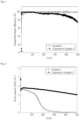
- the pouch cell of Example 1 including the separator according to Manufacturing Example 1 manufactured by electrospinning did not check a decrease in charge/discharge efficiency during 500 charge/discharge cycles, but the pouch cell of Comparative Example 3 was shown to decrease by 5% or more at the 500th cycle by starting to decrease from the 200th cycle.
- the pouch cell of Example 1 including the separator according to Manufacturing Example 1 manufactured by electrospinning exhibited a capacity reduction rate of less than 8% during 200 charge/discharge cycles, whereas the pouch cell of Comparative Example 3 was found to be reduced by 70% or more.
- Two sheets of a PET film (35 ⁇ m) with an area of 5 ⁇ 5 cm 2 were disposed on two sheets of A4 paper, and a separator with an area of 5 ⁇ 5 cm 2 was disposed on the PET film.
- One sheet of the PET film (35 ⁇ m) having an area of 5 ⁇ 5 cm 2 was again disposed on the separator, and two sheets of A4 paper were disposed on the PET film.
- Pressure was applied to the A4 paper disposed up and down using a surface rolling mill (Rhotec, pressing machine, V-30) at conditions of 70°C and 5.2 MPa for 10 seconds.
- a SUS spacer was used as a working electrode and a counter electrode, and the separators before and after compression resistance evaluation were cut into a circular shape with a diameter of 19 mm and inserted between these electrodes to manufacture coin-type cells (blocking cells), and then the ionic conductivities were measured by measuring the impedances.
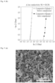
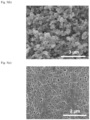
- FIGS. 3 and 4 Compression resistance evaluation and ionic conductivities of the separator of Manufacturing Example 1 and the separator of Comparative Example 3 were measured, and the results are shown in FIGS. 3 and 4 , respectively.
- the separator of Manufacturing Example 1 showed a resistance rise rate of 23.6% before and after compression
- the separator of Comparative Example 3 showed a resistance rise rate of 68.5% before and after compression.
- the separator according to Manufacturing Example 1 was left at 150°C for 30 minutes to check dimensional change and volume change.
- the volume change rate of the separator according to Manufacturing Example 1 was shown to be 0%.
- the separators manufactured in Manufacturing Examples 5 to 7 were punched to 19 ⁇ , and an electrolyte was added to manufacture coin cells.
- the electrolyte included one in which ethylene carbonate (EC), dimethyl carbonate (DMC), and ethyl methyl carbonate (EMC) were mixed at a weight ratio of 3: 4: 3, and which included, as additives, 3 mol of vinylene carbonate (VC), 1.5 mol of propanesultone (PS), 1 mol of ethylene sulfate (ESa), and 1 mol of lithium salt (LiPF 6 ).
- EC ethylene carbonate
- DMC dimethyl carbonate
- EMC ethyl methyl carbonate
- LiPF 6 lithium salt
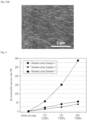
- the separators according to Manufacturing Examples 5 and 6 showed the air permeability increase rate of less than 100% even after compression by including a layer containing an inorganic material in an excessive amount compared to the polymer resin. Meanwhile, the separator according to Manufacturing Example 7 showed an air permeability increase rate of 390% according to compression. Such results, in Manufacturing Example 7, are due to the fact that the pores of the separator are clogged or the uniformity is lowered due to structural collapse of the inorganic particles and polymer resin included in the coating layer.
- a positive electrode slurry containing lithium manganese composite oxide (NCMA) as a positive electrode active material was applied to an aluminum thin film, dried, and then compressed in a roll mill to prepare a positive electrode having a porosity of 26% and a capacity per unit area of 4.5 mAh/cm 2 .
- a negative electrode slurry containing pure Si as a negative electrode active material was applied to a copper thin film, dried, and then compressed in a roll mill to prepare a negative electrode having a porosity of 40% and a capacity per unit area of 8.5 mAh/cm 2 .
- fluoroethylene carbonate (FEC) and ethyl methyl carbonate (EMC) were mixed at a volume ratio of 3:7, and LiPF 6 was added to prepare an electrolyte having a LiPF 6 concentration of 1.0M.
- Pouch-type mono cells were manufactured as electrochemical devices using the positive electrode, negative electrode, and electrolyte prepared as described above and the separators of Manufacturing Examples 5 to 7.
- the positive electrode was cut to a size of 4 cm ⁇ 4 cm
- the upper end of 0.5 cm ⁇ 1 cm was welded with an aluminum tab having a width of 1 cm.
- the negative electrode was cut to a size of 4.5 cm ⁇ 4.5 cm
- the upper end of 0.5 cm ⁇ 1 cm was welded with a nickel tab having a width of 1 cm.
- the separators After cutting the separators to a size of 5 cm ⁇ 5 cm, they were put into pouches in the order of the positive electrode, the separators, and the negative electrode, the three corners of the pouches were sealed at 250°C to inject 250 mL of the electrolyte, and they were sealed in order under vacuum and high temperatures to manufacture pouch cells.
- a jig was connected to a room temperature chamber in a state in which the pouch cells were fully filled. Thereafter, it was allowed to reach 130°C at a temperature raise rate of 5°C/min, and then whether the cells were ignited or not was evaluated while maintaining it for 30 minutes. During the temperature rise or while maintaining the temperature at 130°C, the temperature or voltage of the cells rapidly rose and ignited was evaluated as Fail, and that of the cells maintained normally after 30 minutes was evaluated as Pass. [Table 4] Classification Shutdown temperature (°C) Whether it passed hot box evaluation or not Manufacturing Example 5 124 Pass Manufacturing Example 6 182 Fail Manufacturing Example 7 136 Fail
Landscapes
- Chemical & Material Sciences (AREA)
- General Chemical & Material Sciences (AREA)
- Chemical Kinetics & Catalysis (AREA)
- Electrochemistry (AREA)
- Engineering & Computer Science (AREA)
- Textile Engineering (AREA)
- Inorganic Chemistry (AREA)
- Materials Engineering (AREA)
- Mechanical Engineering (AREA)
- Composite Materials (AREA)
- Ceramic Engineering (AREA)
- Manufacturing & Machinery (AREA)
- Dispersion Chemistry (AREA)
- Cell Separators (AREA)
- Electric Double-Layer Capacitors Or The Like (AREA)
- Secondary Cells (AREA)
- Spinning Methods And Devices For Manufacturing Artificial Fibers (AREA)
Abstract
Description
- The present disclosure claims the benefits of the filing dates of
Korean Patent Application No. 10-2022-0083685 filed with the Korean Intellectual Property Office on July 7, 2022 Korean Patent Application No. 10-2022-0107931 filed with the Korean Intellectual Property Office on August 26, 2022 - The present disclosure relates to a method for manufacturing a separator for an electrochemical device, including a silicon-based negative electrode, and a separator for an electrochemical device manufactured thereby.
- An electrochemical device converts chemical energy into electrical energy using an electrochemical reaction. Recently, lithium secondary batteries that have high energy density and voltage, have long cycle life, and are usable in various fields have been widely used.
- The lithium secondary batteries may include an electrode assembly manufactured of a positive electrode, a negative electrode, and a separator disposed between the positive electrode and the negative electrode, and the electrode assembly may be manufactured by being accommodated in a case along with an electrolyte. The positive electrode may provide lithium ions, and the lithium ions may pass through a separator made of a porous material and move to the negative electrode. The negative electrode preferably has an electrochemical reaction potential close to that of lithium metal and is capable of intercalating and deintercalating lithium ions. A negative electrode including a carbon-based active material such as graphite has advantages in that it is stable and exhibits excellent cycle life since there is a small change in crystal structure due to intercalation and deintercalation of lithium ions.
- Recently, as demand for lithium secondary batteries having larger capacity and higher energy density such as electric vehicles and energy storage devices has increased, the development of non-carbon based active materials using silicon, etc., with higher capacity than carbon-based active materials has been made. However, since the volume of the lithium secondary batteries including a silicon-based negative electrode rapidly expands during the charging process, the separator may be deformed as charging and discharging are repeated, and deformation or damage to the separator may lead to poor insulation or degeneration of lifespan of the lithium secondary batteries.
- Therefore, research is being conducted on a separator having compression resistance that does not cause deformation even when the negative electrode expands in an electrochemical device using a silicon-based negative electrode.
- An object of the present disclosure is to provide a separator having a structure that is not deformed or damaged even when compressed by a negative electrode that expands during charging in an electrochemical device including a silicon-based negative electrode, a method for manufacturing the separator, and an electrochemical device including the separator.
- Furthermore, an object of the present disclosure is to provide a separator having a structure capable of preventing a short circuit of an electrode when an electrochemical device including a silicon-based negative electrode is exposed to high temperatures, a method for manufacturing the separator, and an electrochemical device including the separator.
- One aspect of the present disclosure provides a separator for an electrochemical device, including a silicon-based negative electrode, wherein the separator is a freestanding porous separator that does not contain a polyolefin substrate, and includes a polymer binder and inorganic particles, and the content of the inorganic particles is greater than the content of the polymer binder based on the total weight of the separator.
- The separator may include 60 to 95% by weight of the inorganic particles based on the total weight of the separator.
- The separator may satisfy a thickness of 15 to 45 µm, and have a value defined by
Equation 1 below of 1 to 18%:

- In
Equation 1, - T1 is an initial thickness of the separator, and
- T2 means a thickness after pressing the separator at 5.2 MPa and 70°C for 10 seconds with a surface rolling mill.
- The separator may further include a second layer formed on at least one surface of the separator, the second layer may include a polymer resin different from the polymer binder, and the polymer binder may have a higher melting point than the polymer resin.
- The separator may satisfy a thickness of 10 to 45 µm, and may have an air permeability change rate of less than 100% when pressurized at 80°C and a pressure of 7.8 MPa for 10 seconds.
- Another aspect of the present disclosure provides an electrochemical device including a positive electrode, a silicon-based negative electrode, and the separator for an electrochemical device according to one aspect, which is positioned between the positive electrode and the silicon-based negative electrode.
- The silicon-based negative electrode may include one or more silicon-based active materials selected from the group consisting of Si, SiOx (0<x<2), SiC, and Si alloys.
- Another aspect of the present disclosure provides a method for manufacturing a separator for an electrochemical device, including a silicon-based negative electrode, the method including a step of forming a freestanding porous separator by simultaneously electrospinning a first spinning solution containing a polymer binder and a second spinning solution containing inorganic particles, wherein the second spinning solution has a flow rate greater than that of the first spinning solution.
- The inorganic particles may be one or more selected from the group consisting of SiO2, Al2O3, AlOOH, TiO2, ZrO2, BaSO4, BaTiO3, ZnO, MgO, Mg(OH)2, Al(OH)3, Pb(Zr,Ti)O3, Pb(Mg1/3Nb2/3)O3-PbTiO3(PMN-PT), HfO2, SrTiO3, SnO2, CeO2, MgO, NiO, CaO, Y2O3, SiC, ZnSn(OH)6, Zn2SnO4, ZnSnO3, Sb2O3, Sb2O4, and Sb2O5.
- The polymer binder may be one or more selected from the group consisting of polyethylene terephthalate, polybutylene terephthalate, polyamide, polyimide, polyetherimide, polyacrylonitrile, polyvinyl alcohol, polyaramid, and polystyrene.
- The step of forming the freestanding porous separator may be electrospinning the first spinning solution and the second spinning solution at a flow rate ratio of 1:8 to 1:100.
- The method for manufacturing a separator for an electrochemical device may further include a step of pressurizing the formed freestanding porous separator at 25 to 60°C.
- The method for manufacturing a separator for an electrochemical device may further include a step of forming a second layer by electrospinning a third spinning solution containing a polymer resin on at least one surface of the porous separator, wherein the polymer binder may have a higher melting point than the polymer resin.
- The second layer may be formed by being disposed on the porous separator and rolled.
- The rolling may be performed at a temperature lower than the melting point of the polymer resin.
- The polymer resin may be one or more selected from the group consisting of polyvinylidene fluoride, polyvinylidene fluoride-hexafluoropropylene, polyethylene glycol, polypropylene glycol, polyethylene oxide, and polymethyl methacrylate.
- The separator for an electrochemical device according to the present disclosure satisfies a thickness of 15 to 45 µm, has a value defined by
Equation 1 above of 1 to 18% or less, and has a resistance rise rate of 50% or less after compression, and the separator is not deformed or damaged even when the separator is compressed according to the expansion of the negative electrode containing a silicon-based active material. - Further, the separator for an electrochemical device according to the present disclosure further includes a second layer having a lower melting point than the porous separator including a polymer binder and inorganic particles so that when the electrochemical device is exposed to high temperatures, the pores of the second layer can be allowed to be closed to prevent short circuit of the electrodes.
- Therefore, the electrochemical device including the separator can provide improved capacity and energy density according to the use of a silicon-based negative electrode, and can provide stable cycle characteristics at the same time.
-
-
FIG. 1 is a graph showing charge and discharge efficiency (Coulombic efficiency) of pouch cells according to Example 1 and Comparative Example 3 in Experimental Example 2 of the present disclosure according to charge and discharge cycles. -
FIG. 2 is a graph showing areal capacity of pouch cells according to Example 1 and Comparative Example 3 in Experimental Example 2 of the present disclosure according to charge and discharge cycles. -
FIG. 3 is a graph showing thicknesses before and after compression of the separators according to Manufacturing Example 1 and Comparative Example 3 in Experimental Example 3 of the present disclosure. -
FIG. 4 is graphs showing (a) ion conductivity of the separator according to Manufacturing Example 1 and (b) ion conductivity of the separator according to Comparative Example 3 in Experimental Example 3 of the present disclosure. -
FIG. 5 is, in Experimental Example 3 of the present disclosure, (a) an SEM image of a separator according to Manufacturing Example 1 before pressurization, (b) an SEM image of a separator according to Manufacturing Example 1 after pressurization, (c) an SEM image of a separator according to Comparative Example 3 before pressurization, and (d) an SEM image a separator according to Comparative Example 3 after pressurization. -
FIG. 6 is a graph showing air permeability before and after compression of the separators according to Manufacturing Examples 5 to 7 in the Experimental Examples of the present disclosure. - Hereinafter, each configuration of the present disclosure will be described in more detail so that those skilled in the art to which the present disclosure pertains can easily practice it, but this is only one example, and the scope of rights of the present disclosure is not limited by the following contents.
- The term "include" used in the present specification is used when listing materials, compositions, devices, and methods useful in the present disclosure and is not limited to the listed examples.
- "About" and "substantially" used in the present specification are used as a range of values or degrees or a meaning close thereto, taking into account of inherent manufacturing and material tolerances, and are used to prevent unfair use by infringers of the disclosed contents in which exact or absolute values provided to help understanding of the present disclosure are mentioned.
- "The electrochemical device" used in the present specification may mean a primary battery, a secondary battery, a super capacitor, and the like.
- "The particle diameter" used in the present specification means D50, which is a particle diameter corresponding to 50% of the cumulative distribution of the number of particles according to the particle diameter, unless otherwise specified.
- "The molecular weight" used in the present specification means a weight average molecular weight (Mw) unless otherwise specified, and the weight average molecular weight corresponds to the molecular weight in terms of polystyrene measured by gel permeation chromatography (GPC) using a monodisperse polystyrene polymer as a standard substance.
- One embodiment of the present disclosure provides a method for manufacturing a separator for an electrochemical device, including a silicon-based negative electrode, the method including a step of forming a freestanding porous separator by electrospinning a first spinning solution containing a polymer binder and a second spinning solution containing inorganic particles at the same time.
- A conventional porous separator forms a coating layer containing inorganic particles and a polymer binder on at least one surface of a porous substrate, and the porous substrate used a polyolefin substrate or nonwoven fabric prepared through a dry or wet process. The freestanding porous separator refers to a separator in which a pore structure is formed using inorganic particles and a polymer binder without a porous substrate as described above. Separators that do not include a porous substrate may be vulnerable to external forces and have low compression resistance as their external shape is formed only with inorganic particles and a polymer binder.
- One embodiment of the present disclosure provides a freestanding porous separator having excellent compression resistance by configuring a high content of inorganic particles compared to a binder without using a polyolefin substrate. Specifically, in one embodiment of the present disclosure, the second spinning solution has a flow rate greater than that of the first spinning solution in the step of forming the freestanding porous separator.
- Compression resistance may be expressed as a resistance rise rate or thickness ratio before and after pressurizing the separator under predetermined conditions. Excellent compression resistance means that lithium ions may move smoothly by maintaining the original pore structure even if the separator is pressurized due to low compression resistance. In addition, excellent compression resistance means that durability against external force is excellent so that deformation or damage of the separator is minimized or does not occur.
- In one embodiment of the present disclosure, a relatively small amount of a polymer binder may be used compared to other manufacturing methods such as die coating, bar coating, dip coating, and roll coating by manufacturing a freestanding porous separator by electrospinning. Through this, it may be possible to manufacture a separator having a relatively high inorganic particle content while reducing the content of the polymer binder. At the same time, electrospinning may achieve a uniform distribution of inorganic particles compared to other manufacturing methods so that it is suitable for manufacturing a separator with physical properties suitable for use in an electrochemical device including a silicon-based negative electrode.
- The silicon-based negative electrode may include one or more silicon-based active materials selected from the group consisting of Si, SiOx (0<x<2), SiC, and Si alloys. For example, the Si alloys may include a LiSi alloy, a CoSi alloy, or a TiSi alloy. Preferably, the silicon-based active material may include 50% by weight or more of pure Si based on the total weight. More preferably, the silicon-based active material may be made of only pure Si.
- Electrospinning may be performed by applying a voltage between a nozzle through which a polymer solution is discharged and a collector on which the polymer solution discharged from the nozzle is collected. The nozzle may be connected to a container such as a syringe or the like storing the polymer solution to receive the polymer solution at a predetermined flow rate. The nozzle may be charged with positive or negative charges, and the collector may be charged with a charge opposite to that of the nozzle or may be grounded. For example, the collector may be a flat plate made of a metal material that collects the polymer solution being spun in the form of fibers, but the shape or size thereof is not limited.
- First, droplets of a polymer maintained by surface tension may form at the end of the nozzle. At this time, when a high voltage of about 10 to 30 kV is applied to the nozzle, the Coulomb's force due to the external electric field may become greater than the surface tension of the polymer droplets, and the polymer droplets may exhibit a Taylor cone shape. Preferably, a high voltage of about 12 to 18 kV is applied to the nozzle so that a jet of polymer fibers may be spun and stretched from the Taylor cone-shaped polymer droplets, and the polymer fibers may move in the direction of the collector and may be collected, and then solidified.
- The step of forming the freestanding porous separator includes preparing a first spinning solution containing a polymer binder. The first spinning solution may be a polymer binder solution in which a polymer binder is dissolved in a solvent.
- The polymer binder may be a polymer having a molecular weight of 100,000 to 200,000, preferably 120,000 to 180,000, and more preferably 140,000 to 160,000. If the molecular weight of the polymer binder is lower than the above-described range, electrospinning cannot be performed in a state in which the shape of the fiber is maintained. If the molecular weight of the polymer binder is higher than the above-described range, the viscosity of the second spinning solution increases so that smooth electrospinning cannot be performed.
- The polymer binder may be one or more selected from the group consisting of polyethylene terephthalate (PET), polybutylene terephthalate, polyamide, polyimide, polyetherimide, polyacrylonitrile (PAN), polyvinyl alcohol (PVA), polyaramid, and polystyrene. Preferably, the polymer binder may be a polymer having excellent heat resistance at 150 to 200°C, may have excellent thermal stability of a separator manufactured, and may prevent internal short circuit of the electrochemical device. More preferably, the polymer binder may be one or more selected from the group consisting of polyethylene terephthalate, polyacrylonitrile, and polyphenylene oxide.
- The solvent may be one or more organic solvents such as alcohol, acetone, dimethylacetamide (DMAc), dimethylformamide (DMF), and methylenechloride, but is not limited thereto. The solvent may be one which evaporates after the step of forming the freestanding porous separator so that it does not remain in the separator.
- The first spinning solution may include about 5 to 20% by weight of the polymer binder based on the total weight. Preferably, the polymer binder may have a content of about 5 to 12% by weight. More preferably, the polymer binder may have a content of about 8 to 10% by weight. If the content of the polymer binder is lower than the above-described range, the viscosity of the second spinning solution is lowered, and thus the fiber shape cannot be maintained during electrospinning. If the content of the polymer binder is higher than the above-described range, the viscosity of the first spinning solution increases, and thus smooth electrospinning cannot be performed.
- The step of forming the freestanding porous separator includes preparing a second spinning solution containing inorganic particles. The second spinning solution may be a dispersion of inorganic particles in which inorganic particles are mixed with a dispersion medium.
- The inorganic particles may be inorganic nanoparticles having an average particle diameter (D50) of 10 to 1,000 nm, preferably 10 to 500 nm, and more preferably 200 to 300 nm. The inorganic particles may be connected to and fixed to adjacent inorganic particles by a polymer binder to be described later, and an interstitial volume between the inorganic particles may be formed as pores of the separator. When the average particle diameter of the inorganic particles is included in the above-described range, uniform pores may be formed in the separator. A separator having more uniform pores may facilitate the movement of lithium ions and increase the impregnation rate of the electrolyte, thereby contributing to improved battery performance.
- The inorganic particles may include one or more selected from the group consisting of SiO2, Al2O3, AlOOH, TiO2, ZrO2, BaSO4, BaTiO3, ZnO, MgO, Mg(OH)2, Al(OH)3, Pb(Zr,Ti)O3, Pb(Mg1/3Nb2/3)O3-PbTiO3(PMN-PT), HfO2, SrTiO3, SnO2, CeO2, MgO, NiO, CaO, Y2O3, SiC, ZnSn(OH)6, Zn2SnO4, ZnSnO3, Sb2O3, Sb2O4, and Sb2O5. The inorganic materials are electrochemically stable, and thus no chemical reaction may occur within the operating voltage range of the electrochemical device. Preferably, the inorganic materials may be one or more selected from the group consisting of SiO2, Al2O3, AlOOH, TiO2, ZrO2, and Al(OH)3.
- The dispersion may be a colloidal solution formed by mixing the inorganic particles and the dispersion medium. The dispersion medium may be water, alcohol, or the like that does not substantially dissolve the inorganic particles, but is not limited thereto. The dispersion medium may evaporate after the step of forming the freestanding porous separator and not remain in the separator.
- The second spinning solution may include about 5 to 15% by weight of the inorganic particles with respect to the total weight. Preferably, the inorganic particles may have a content of about 8 to 12% by weight. The inorganic particles may exhibit uniform dispersibility in the dispersion medium within the above-described content range, and may achieve uniform distribution of inorganic materials in the separator.
- The second spinning solution may have viscosity by further including a polymer in addition to the inorganic particles. The polymer may be one or more polymers usable as a polymer binder in the present disclosure, but may be different from the polymer binder used in the second spinning solution.
- The preparation of the first spinning solution and the preparation of the second spinning solution may be performed at the same time or at different times regardless of the order.
- The step of forming a freestanding porous separator forms a freestanding porous separator by electrospinning the first spinning solution and the second spinning solution at the same time. In one embodiment of the present disclosure, a freestanding porous separator in which inorganic particles are uniformly dispersed may be manufactured by preparing a first spinning solution containing a polymer binder and a second spinning solution containing inorganic particles, respectively, and simultaneously electrospinning them. It is difficult for a single spinning solution to satisfy all conditions of (i) it should have an appropriate boiling point considering evaporation after spinning, (ii) it should be usable for electrospinning, (iii) it should dissolve polymer binders well, and (iv) it should disperse inorganic particles well. The simultaneous electrospinning of the first spinning solution and the second spinning solution may simultaneously satisfy the above-described conditions (i) to (iv), and as a result, a porous separator in which inorganic particles are uniformly dispersed without a separate dispersant may be manufactured.
- The first spinning solution and the second spinning solution may be each stored in a container equipped with a nozzle and then electrospun with respect to one collector. For example, the container may be a syringe, and an injection flow rate of the syringe in which the first spinning solution is stored may be greater than an injection flow rate of the syringe in which the second spinning solution is stored. The electrospinning method of the first spinning solution and the second spinning solution is not limited as long as the inorganic particles and the polymer binder may be allowed to be uniformly distributed in a separator manufactured. Preferably, the first spinning solution and the second spinning solution may be well mixed with each other on the collector, and spun to become a flat plate shape.
- The first spinning solution and the second spinning solution may be electrospun at a flow rate ratio of 1:8 to 1:100. For example, the first spinning solution may be electrospun at a flow rate of 1 to 10 µl/min. The second spinning solution may be electrospun at a flow rate of 80 to 100 µl/min. When the above-described flow rate ratio is satisfied, the separator manufactured may secure sufficient compression resistance and be applied to an electrochemical device using a silicon-based negative electrode.
- The first spinning solution and the second spinning solution may be spun in the form of fibers and collected on the collector. The method for manufacturing a separator may further include a step of leaving the freestanding porous separator at room temperature or drying it in an oven at a temperature of room temperature to 60°C after the step of forming the freestanding porous separator to evaporate and remove the solvent and dispersion remaining without evaporation during the electrospinning process.
- The method for manufacturing a separator for an electrochemical device may further include a step of pressurizing the separator formed in the step of forming the freestanding porous separator at 25 to 60°C.
- The step of pressurizing the separator may be rolling the formed separator at a rolling rate of 10 to 50% and then rolling the separator to a thickness of 15 to 45 µm using a rolling mill. If the rolling temperature, pressure, and rolling rate are out of the above-described ranges, inorganic particles included in the separator may be destroyed. The rolling mill may be a roll mill in which a separator is rolled by injecting it while upper and lower rolls are rotating. Preferably, in the step of pressurizing the separator, the separator may have a thickness of 20 to 40 µm after rolling by rolling the separator at 25 to 40% using a rolling mill.
- The separator for an electrochemical device manufactured according to the method as described above is a freestanding porous separator that does not form a coating layer containing inorganic particles and a polymer binder on a porous substrate, and the content of inorganic particles is high compared to the polymer binder, and the inorganic particles are uniformly dispersed in the separator. The separator does not undergo deformation or damage even when the negative electrode including the silicon-based active material expands, and has excellent compression resistance so that the resistance rise rate may be maintained at 50% or less even after repeated charging and discharging of the electrochemical device.
- The method for manufacturing a separator for an electrochemical device may further include a step of forming a second layer by electrospinning a third spinning solution containing a polymer resin on at least one surface of the freestanding porous separator. The freestanding porous separator may be a first layer, and a second layer including the polymer resin may be stacked on at least one surface of the first layer.
- The third spinning solution may be a polymer solution in which the polymer resin is dissolved in a solvent. The polymer resin may be different from the polymer binder, and the polymer binder may have a higher melting point than the polymer resin.
- The polymer resin may be a polymer having a molecular weight of 10,000 to 200,000, preferably 12,000 to 100,000, and more preferably 15,000 to 20,000. If the molecular weight of the polymer resin is lower than the above-described range, electrospinning cannot be performed in a state in which the shape of the fiber is maintained. If the molecular weight of the polymer resin is higher than the above-described range, the viscosity of the third spinning solution increases so that smooth electrospinning cannot be performed.
- The polymer resin may be one or more selected from the group consisting of polyvinylidene fluoride, polyvinylidene fluoride-hexafluoropropylene, polyethylene glycol, polypropylene glycol, polyethylene oxide, and polymethyl methacrylate.
- The solvent may be one or more organic solvents such as alcohol, acetone, dimethylacetamide (DMAc), dimethylformamide (DMF), and methylenechloride, but is not limited thereto. The solvent may evaporate after the step of forming the second layer and not remain in the separator.
- The third spinning solution may include about 5 to 20% by weight of the polymer resin based on the total weight. Preferably, the polymer resin may have a content of about 5 to 12% by weight. More preferably, the polymer resin may have a content of about 8 to 10% by weight. If the content of the polymer resin is lower than the above-described range, the viscosity of the third spinning solution is lowered, and thus the fiber shape cannot be maintained during electrospinning. If the content of the polymer resin is higher than the above-described range, the viscosity of the third spinning solution increases, and thus smooth electrospinning cannot be performed.
- The preparation of the third spinning solution may be performed at the same time as the preparation of the first and second spinning solutions, or at different times regardless of the order.
- The third spinning solution may be stored in a container equipped with a nozzle and then electrospun with respect to the collector. The third spinning solution may have a flow rate equal to or higher than that of the first spinning solution.
- The third spinning solution may be spun in the form of fibers and collected on the collector. The step of forming of the second layer may further include a step of leaving it at room temperature or drying it in an oven at a temperature of room temperature to 60°C after electrospinning to evaporate and remove the solvent without evaporation during the electrospinning process. A pore structure may be formed in the second layer during the electrospinning of the third spinning solution and the evaporation of the solvent.
- The polymer resin may have a melting point lower than that of the polymer binder, and the second layer may have a melting point lower than that of the first layer. The second layer may function as a shutdown layer in the separator. For example, when the temperature of the second layer becomes higher than a predetermined temperature as a large current suddenly flows due to a short circuit in an electrochemical device, the pore structure of the second layer is first shut down, and thus a short circuit of the electrode and an additional temperature rise may be prevented.
- The step of stacking the second layer on the first layer may be rolling the second layer and the first layer. The rolling may be performed at a temperature lower than the melting point of the polymer resin. The rolling may adhere the second layer and the first layer while not closing the pore structure of the second layer. The rolling may use a roll mill that rolls it by injecting the separator while the upper and lower rolls are rotating.
- The separator for an electrochemical device manufactured according to the method as described above is a freestanding porous separator that does not include a porous substrate and includes a first layer including a polymer binder and inorganic particles and a second layer including a polymer resin. The first layer has a high content of inorganic particles compared to the polymer binder based on the total weight of the first layer, and has the inorganic particles uniformly dispersed therein. The separator including the first layer is not deformed or damaged even when the negative electrode including the silicon-based active material is expanded, and has excellent compression resistance so that even when charging and discharging of the electrochemical device is repeated, the rate of change in air permeability is shown to be low. The second layer includes a polymer resin having a melting point lower than that of the polymer binder of the first layer so that when the electrochemical device is exposed to a temperature higher than a predetermined temperature, the second layer is first shut down, and thus a short circuit of the electrode may be prevented.
- Another embodiment of the present disclosure provides a separator for an electrochemical device, including a silicon-based negative electrode. The separator is a freestanding porous separator that does not include a polyolefin substrate, and includes a polymer binder and inorganic particles, but the content of the inorganic particles is greater than that of the polymer binder based on the total weight of the separator. The separator may be manufactured according to the above description and the method for manufacturing a separator according to the previous embodiment, and the same description as in the previous embodiment is replaced with the description of the above-described embodiment.
- The separator is manufactured by electrospinning a first spinning solution containing a polymer binder and a second spinning solution containing inorganic particles at the same time. The contents of the polymer binder and inorganic particles included in the separator may be adjusted by adjusting the flow rates of the first spinning solution and the second spinning solution during electrospinning. When manufacturing the separator, the electrospinning flow rate of the second spinning solution is made to be greater than the electrospinning flow rate of the first spinning solution so that a separator having a content of the inorganic particles greater than that of the polymer binder based on the total weight of the separator may be manufactured. Specifically, the separator may include 60 to 95% by weight of the inorganic material based on the total weight of the separator. Preferably, the separator may include 85 to 95% by weight of the inorganic material based on the total weight. When the content of the inorganic material is within the above-described range, the separator may provide compression resistance usable in an electrochemical device using a silicon-based negative electrode.
- The separator may have a thickness of 15 to 45 µm. Preferably, the separator may have a thickness of 20 to 40 µm. When the thickness of the separator is within the above-described range, deformation or damage to the separator due to expansion of a negative electrode including a silicon-based active material may be minimized. If the thickness of the separator is lower than the above-described range, the separator may be damaged due to expansion of the separator. If the thickness of the separator is higher than the above-described range, the movement of lithium ions through the separator becomes difficult.
- The separator may have a resistance rise rate of 50% or less before and after compression. For example, when the separator is compressed for 10 seconds at conditions of 70°C and 5.2 MPa using a surface rolling mill (Rhotec, pressing machine, V-30), the change in resistance before and after compression may be within 0.01 to 1 Ohm.
- The separator may have a thickness change rate of 18% or less before and after compression defined by
Equation 1 below. Preferably, the separator may have a thickness change rate of 1 to 18% before and after compression. More preferably, the thickness change rate before and after compression may be 1 to 15%. -

- In
Equation 1, - T1 is an initial thickness of the separator, and
- T2 means a thickness after pressing the separator at 5.2 MPa and 70°C for 10 seconds in a surface rolling mill (Rhotec pressing machine V-30).
- A separator satisfying the resistance rise rate or thickness change rate range maintains a pore structure before and after pressurization, enabling smooth movement of lithium ions, and even if a negative electrode containing a silicon-based active material expands, deformation or damage to the separator may be minimized or not occur.
- The separator may not substantially undergo dimensional change at a high temperature of 150°C or higher, and may have a volume change rate of 1.5% or less.
- The separator may have pores with an average size of 500 to 1,000 nm, and have a porosity of 50 to 60%. The separator may have a porosity that is shown to have an air permeability of 100 sec/100cc or less.
- The separator may be a two-layer structure separator further including a second layer formed on at least one surface of the separator. The second layer may include a polymer resin different from the polymer binder, and the polymer binder may have a higher melting point than the polymer resin.
- The separator may include a plurality of first layers or second layers.
- The first layer and the second layer may have a thickness ratio of 3:1 to 9:1. The shutdown function of the second layer may be secured while preventing damage to the separator due to expansion of the negative electrode within the above-described range.
- The compression resistance of the separator may be evaluated by the rate of change in air permeability (Gurley) values before and after compression. For example, when the separator is compressed using a surface rolling mill at conditions of 80°C and 7.8 MPa for 10 seconds, the rate of change in air permeabilities before and after compression may be less than 100%.
- A separator satisfying the air permeability change rate range as described above maintains a pore structure before and after pressurization, enabling smooth movement of lithium ions, and even when a negative electrode containing a silicon-based active material expands, deformation or damage to the separator may be minimized or not occur.
- Another embodiment of the present disclosure provides an electrochemical device including a positive electrode, a silicon-based negative electrode, and a separator as described above. For example, the electrochemical device may be a lithium secondary battery including a positive electrode providing lithium ions. The electrochemical device may further include an electrolyte.
- The positive electrode and the silicon-based negative electrode may be obtained by applying and drying an active material on at least one surface of each current collector. The silicon-based negative electrode may use the above-described active material.
- For example, the positive electrode active material may include: lithium cobalt oxide (LiCoO2); lithium nickel oxide (LiNiO2); lithium manganese oxides such as the formula Li1+xMn2-xO4 (where x is 0 to 0.33), LiMnO3, LiMn2O3, LiMnO2, etc.; lithium copper oxide (Li2CuO2); vanadium oxides such as LiVsOs, LiFe3O4, V2O5, Cu2V2O7, etc.; Ni site-type lithium nickel oxide represented by the formula LiNi1-xMxO2 (where M = Co, Mn, Al, Cu, Fe, Mg, B, or Ga, and x = 0.01 to 0.3); lithium manganese composite oxide represented by the formula LiMn2-xMxO2 (where M = Co, Ni, Fe, Cr, Zn, or Ta, and x = 0.01 to 0.1) or Li2Mn3MO8 (where M = Fe, Co, Ni, Cu, or Zn); LiMn2O4 in which Li part of the formula is substituted with an alkaline earth metal ion; disulfide compounds; and Fe2(MoO4)3, but is not limited thereto.
- A material having conductivity without causing chemical change in the electrochemical device may be used in the current collector. For example, a current collector for a positive electrode may include aluminum, nickel, titanium, fired carbon, stainless steel; or the surface of aluminum or stainless steel which is surface-treated with carbon, nickel, titanium, silver, or the like, but is not limited thereto. For example, a current collector for a negative electrode may include copper, nickel, titanium, fired carbon, stainless steel; or the surface of copper or stainless steel which is surface-treated with carbon, nickel, titanium, silver, or the like, but is not limited thereto. The current collector may be in various forms such as a thin metal plate, a film, a foil, a net, a porous body, and a foam.
- The electrolyte may be a non-aqueous electrolyte containing a lithium salt, and may include a lithium salt and a non-aqueous organic solvent, an organic solid electrolyte, an inorganic solid electrolyte, and the like.
- Examples of the non-aqueous organic solvent may include an aprotic organic solvent such as N-methyl-2-pyrrolidinone, propylene carbonate, ethylene carbonate, butylene carbonate, dimethyl carbonate, diethyl carbonate, gamma-butyrolactone, 1,2-dimethoxyethane, tetrahydroxy franc, 2-methyl tetrahydrofuran, dimethylsulfoxide, 1,3-dioxolane, formamide, dimethylformamide, dioxolane, acetonitrile, nitromethane, methyl formate, methyl acetate, phosphoric acid triesters, trimethoxy methane, dioxolane derivatives, sulfolane, methyl sulfolane, 1,3-dimethyl-2-imidazolidinone, propylene carbonate derivatives, tetrahydrofuran derivatives, ether, methyl propionate, or ethyl propionate.
- Examples of the organic solid electrolyte may include polyethylene derivatives, polyethylene oxide derivatives, polypropylene oxide derivatives, phosphoric acid ester polymers, poly agitation lysine, polyester sulfide, polyvinyl alcohol, polyvinylidene fluoride, a polymer containing an ionic dissociation group, etc.
- Examples of the inorganic solid electrolyte may include nitrides, halides, and sulfates of Li such as Li3N, LiI, Li5NI2, Li3NLiI-LiOH, LiSiO4, LiSiO4-LiI-LiOH, Li2SiS3, Li4SiO4, Li4SiO4-LiI-LiOH, Li3PO4-Li2S-SiS2, etc.
- The lithium salt is a material that is easily soluble in the non-aqueous electrolyte, and examples thereof may include LiCl, LiBr, LiI, LiClO4, LiBF4, LiB10Cl10, LiPF6, LiCF3SO3, LiCF3CO2, LiAsF6, LiSbF6, LiAlCl4, CH3SO3Li, (CF3SO2)2NLi, chloroborane lithium, lithium lower aliphatic carboxylate, lithium tetraphenylborate, imide, etc.
- The electrochemical device may be manufactured by inserting a positive electrode, a negative electrode, a separator, and an electrolyte into a case or pouch and sealing it. For example, the electrochemical device may be a cylindrical, prismatic, coin-type, or pouch-type lithium secondary battery. Preferably, the electrochemical device may be a cylindrical or pouch-type lithium secondary battery.
- The lithium secondary battery is packed or modularized as a unit cell, and may be used in small devices such as a computer, a mobile phone, a power tool, and the like, and power tools which receive a power and are moved by an electronic motor; electric cars including electric vehicles (EVs), hybrid electric vehicles (HEVs), plug-in hybrid electric vehicles (PHEVs), and the like; electric two-wheeled vehicles including electric bicycles (E-bikes) and electric scooters (E-scooters); electric golf carts; and medium and large devices such as power storage systems and the like.
- Hereinafter, the present disclosure will be described in more detail through specific Examples and Experimental Examples. The following Examples and Experimental Examples are intended to illustrate the present disclosure, but the present disclosure is not limited by the following Examples and Experimental Examples.
- As a binder, 1.8 g of polyacrylonitrile (PAN) having a weight average molecular weight of 150,000 was injected into 18.2 g of dimethylformamide (DMF), and then stirred at 70°C and at a condition of 250 rpm to prepare a first spinning solution, which is a solution of the binder. The first spinning solution was injected into a 10 mL first syringe connected with a nozzle.
- 2.0 g of alumina (Al2O3) having an average particle diameter (D50) of 450 nm as an inorganic material was injected into 5.4 g of n-butanol and 12.6 g of acetone, and then dispersed by bead milling for 1 hour at room temperature to prepare a second spinning solution, which is a dispersion of the inorganic material. A second spinning solution was injected into a 10 mL second syringe having a nozzle connected thereto.
- A collector having a size of 10 cm × 10 cm was disposed under the nozzles of the first syringe and the second syringe, and the collector was grounded. A separator was manufactured by applying a voltage of 18 kV to the nozzle and the collector of each syringe and simultaneously injecting the first syringe at 80 µl/min and the second syringe at 4.5 µl/min for about 180 minutes. Thereafter, in order to remove the remaining solvent and dispersion medium, it was dried at 60°C in a vacuum condition for 12 hours.
- The separator was injected into a roll mill (Rhotec Co.) and compressed to obtain a separator having a thickness of about 30 µm.
- A separator was manufactured in the same manner as in Manufacturing Example 1 except that the first syringe was injected at 90 µl/min, and simultaneously the second syringe was injected at 4.5 µl/min.
- A separator was manufactured in the same manner as in Manufacturing Example 1 except that the first syringe was injected at 55 µl/min, and simultaneously the second syringe was injected at 4.5 µl/min.
- A separator was manufactured in the same manner as in Manufacturing Example 1 except that the first syringe was injected at 70 µl/min, and simultaneously the second syringe was injected at 4.5 µl/min.
- A separator having a thickness of about 12 µm manufactured in the same manner as in Manufacturing Example 1 was used as a first layer, and a third spinning solution was electrospun on one surface of the first layer to manufacture a separator.
- Specifically, polyvinylidene fluoride-hexafluoropropylene (PVDF-HFP) having a weight average molecular weight of 400,000 and a hexafluoropropylene content of 5% by weight was injected into dimethylformamide (DMF) in an amount of 8% by weight, and stirred at 60°C and at a
condition 250 rpm to prepare a third spinning solution. The third spinning solution was injected into a third syringe having a nozzle connected thereto. - The first layer prepared on the collector was disposed under the nozzle of the third syringe, and the collector was grounded. A voltage of 18 kV was applied to the nozzle of the syringe and the collector, and the third syringe was injected at 80 µl/min for about 180 minutes to prepare a second layer on the surface of the first layer. Thereafter, in order to remove the remaining solvent and dispersion medium, it was dried at 60°C and at a vacuum condition for 12 hours to obtain a separator having a thickness of about 15 µm.
- A separator having a thickness of about 15 µm was manufactured in the same manner as in Manufacturing Example 1.
- A coating slurry was prepared by dispersing inorganic particles and a polymer resin at a weight ratio of 8:2 in an acetone solution. Specifically, a mixture of alumina and boehmite was used as the inorganic particles, and a mixture of polyvinylidene fluoride-hexafluoropropylene having a hexafluoropropylene content of 8% by weight, polychlorotrifluoroethylene (CTFE), and a cyano resin was used as the polymer resin.
- The coating slurry was coated on both surfaces of a polyethylene substrate having a thickness of 9 µm by dip coating to form a coating layer having a thickness of about 3 µm and dried to obtain a separator having a thickness of about 15 µm.
- A positive electrode slurry containing lithium manganese composite oxide (NCMA), which is a positive electrode active material, was applied to an aluminum thin film, dried, and then compressed in a roll mill to prepare a positive electrode having a porosity of 26% and a capacity per unit area of 4.5 mAh/cm2.
- A negative electrode slurry containing a carbon-based negative electrode active material was applied to a copper thin film, dried, and then compressed in a roll mill to prepare a negative electrode having a porosity of 40% and a capacity per unit area of 8.5 mAh/cm2.
- As an organic solvent, fluoroethylene carbonate (FEC) and ethyl methyl carbonate (EMC) were mixed at a volume ratio of 3:7, and LiPF6 was added to prepare an electrolyte having a LiPF6 concentration of 1.0M.
- A pouch-type mono cell was manufactured as an electrochemical device using the positive electrode, the negative electrode, and the electrolyte prepared as described above, and the separator manufactured according to Manufacturing Example 1.
- After the positive electrode was cut to a size of 4 × 4 cm2, the upper end of 0.5 × 1 cm2 was welded with an aluminum tab having a width of 1 cm. After the negative electrode was cut to a size of 4.5 × 4.5 cm2, the upper end of 0.5 × 1 cm2 was welded with a nickel tab having a width of 1 cm. After cutting the separator to a size of 5 × 5 cm2, they were put into a pouch in the order of the positive electrode, the separator, and the negative electrode, the three corners of the pouch were sealed at 250°C to inject 250 mL of the electrolyte, and they were sealed in order under vacuum and high temperatures to manufacture a pouch cell.
- A pouch cell was manufactured in the same manner as in Example 1 except that the separator manufactured according to Manufacturing Example 2 was used during manufacturing of the electrochemical device.
- A pouch cell was manufactured in the same manner as in Example 1 except that the separator manufactured according to Manufacturing Example 3 was used during manufacturing of the electrochemical device.
- A pouch cell was manufactured in the same manner as in Example 1 except that the separator manufactured according to Manufacturing Example 4 was used during manufacturing of the electrochemical device.
- A slurry for forming a porous coating layer was prepared by dispersing alumina and boehmite as inorganic particles, and a dispersant (polyvinylpyrrolidone) in acetone, and further adding polyvinylidene fluoride-hexafluoropropylene and chlorotrifluoroethylene as polymer binders. Alumina, boehmite, polyvinylidene fluoride-hexafluoropropylene, chlorotrifluoroethylene, and a dispersant were used at a weight ratio of 66.3: 11.7: 15.5:4.5:2.
- A polyethylene porous substrate having a thickness of 15 µm was coated on both surfaces by a dip coating method using the slurry for forming a porous coating layer. The porous coating layer was formed to a thickness of 4 µm per each surface to manufacture a separator having a total thickness of 23 µm.
- Pouch cells were manufactured in the same manner as in Example 1 except that the separator manufactured according to Comparative Example 1 was used during manufacturing of the electrochemical device.
- When the separators according to Manufacturing Examples 1 to 4 were manufactured to the same thickness, the required rolling rate and air permeability as physical properties of the separator were checked, and the results are shown in Table 1 below.
- Thicknesses of the separators were measured using a thickness measuring unit (Mitutoyo, VL-50S-B).
- Air permeabilities were measuring by measuring the time it takes for 100 cc of air to pass through a separator with a diameter of 28.6 mm and an area of 645 mm2 using a Gurley densometer (Gurley, 4110N).
- When the pouch cells including the separators were manufactured (Examples 1 and 2, and Comparative Examples 1 and 2), whether the pouch cells were driven or not according to the electrospinning flow rate difference of the first spinning solution was checked, and the results are shown in Table 1 below.
[Table 1] Classification Electrospinning flow rate of first spinning solution (µm/min) Thickness of separator (µm) Rolling rate (%) Air permeability (sec/100cc) Whether cell is driven or not Comparative Example 1 (Manufacturing Example 3) 55 30 63 25 × Comparative Example 2 (Manufacturing Example 4) 70 30 50 39 × Example 1 (Manufacturing Example 1) 80 30 40 63 ○ Example 2 (Manufacturing Example 2) 90 30 25 67.4 ○ - Referring to Table 1, it was confirmed that the separators used in Examples 1 and 2 exhibited low rolling rates and normal cell driving was possible by containing inorganic materials in an excessive amount compared to the binder. Meanwhile, it was confirmed that the separators used in Comparative Examples 1 and 2 exhibited high rolling rates and exhibited low air permeabilities, and cell driving was impossible. Such results indirectly indicate that they are results in which the pores of the separator are clogged or the uniformity thereof is lowered due to destruction of inorganic particles in the process of performing pressurization at a high rolling rate.
- The charge and discharge efficiencies (coulombic efficiencies) and areal capacities according to the charge and discharge cycles of the pouch cells according to Example 1 and Comparative Example 3 were checked and shown in
FIGS. 1 and 2 , respectively. - Referring to
FIG. 1 , the pouch cell of Example 1 including the separator according to Manufacturing Example 1 manufactured by electrospinning did not check a decrease in charge/discharge efficiency during 500 charge/discharge cycles, but the pouch cell of Comparative Example 3 was shown to decrease by 5% or more at the 500th cycle by starting to decrease from the 200th cycle. - Referring to
FIG. 2 , the pouch cell of Example 1 including the separator according to Manufacturing Example 1 manufactured by electrospinning exhibited a capacity reduction rate of less than 8% during 200 charge/discharge cycles, whereas the pouch cell of Comparative Example 3 was found to be reduced by 70% or more. - Such a result is due to the deterioration of the lifespan of the pouch cell due to occurrence of deformation in the separator as the negative electrode including silicon (pure-Si) expands.
- Two sheets of a PET film (35 µm) with an area of 5 × 5 cm2 were disposed on two sheets of A4 paper, and a separator with an area of 5 × 5 cm2 was disposed on the PET film. One sheet of the PET film (35 µm) having an area of 5 × 5 cm2 was again disposed on the separator, and two sheets of A4 paper were disposed on the PET film. Pressure was applied to the A4 paper disposed up and down using a surface rolling mill (Rhotec, pressing machine, V-30) at conditions of 70°C and 5.2 MPa for 10 seconds.
- A SUS spacer was used as a working electrode and a counter electrode, and the separators before and after compression resistance evaluation were cut into a circular shape with a diameter of 19 mm and inserted between these electrodes to manufacture coin-type cells (blocking cells), and then the ionic conductivities were measured by measuring the impedances.
- Compression resistance evaluation and ionic conductivities of the separator of Manufacturing Example 1 and the separator of Comparative Example 3 were measured, and the results are shown in
FIGS. 3 and4 , respectively. SEM images (x20K, 10kV) before and after compression resistance evaluation of the separator of Manufacturing Example 1 and the separator of Comparative Example 3 are shown inFIG. 5 . - Referring to
FIG. 3 , it was shown that the thickness of the separator of Manufacturing Example 1 decreased by about 15% after compression, whereas the thickness of the separator of Comparative Example 3 decreased by about 17% after compression. - Referring to
FIG. 4(a) , the separator of Manufacturing Example 1 showed a resistance rise rate of 23.6% before and after compression, and referring toFIG. 4(b) , the separator of Comparative Example 3 showed a resistance rise rate of 68.5% before and after compression. - The results as described above show that the separator according to Manufacturing Example 1 has excellent compression resistance, and thus its resistance rise rate before and after compression is shown to be low, which is in accordance with the SEM image observation results of
FIG. 5 . Specifically,Fig. 5 (a) the separator according to Manufacturing Example 1 before pressurization andFig.5 (b) the separator according to Manufacturing Example 1 after pressurization maintained the pore structure before and after pressurization well. However, when comparing the separator according to Comparative Example 3 before pressurization (FIG. 5(c) ) and the separator according to Comparative Example 3 after pressurization (FIG. 5(d) ), it was confirmed in Comparative Example 3 that the structure of the pores collapsed, such that some of the pores were blocked after pressurization. - The separator according to Manufacturing Example 1 was left at 150°C for 30 minutes to check dimensional change and volume change.
- The volume change rate of the separator according to Manufacturing Example 1 was shown to be 0%.
- Thicknesses, air permeabilities, and electrical resistances of the separators according to Manufacturing Examples 5 to 7 were checked, and the results are shown in Table 2 below. The thicknesses and air permeabilities of the separators were confirmed in the same manner as in the above-described Experimental Example.
- In order to manufacture 2016 sized coin cells, the separators manufactured in Manufacturing Examples 5 to 7 were punched to 19 ø, and an electrolyte was added to manufacture coin cells.
- After leaving the coin cells for 3 hours, resistances of the coin cells were measured using an electrochemical impedance spectroscopy (EIS) device.
- As the EIS device, Solartron's 1255B model was used, a frequency of 104 to 105 Hz was applied, and values obtained by recording the X-intercept values of the measured graph were recorded as electrical resistances in Table 2 below.
- The electrolyte included one in which ethylene carbonate (EC), dimethyl carbonate (DMC), and ethyl methyl carbonate (EMC) were mixed at a weight ratio of 3: 4: 3, and which included, as additives, 3 mol of vinylene carbonate (VC), 1.5 mol of propanesultone (PS), 1 mol of ethylene sulfate (ESa), and 1 mol of lithium salt (LiPF6).
[Table 2] Classification Thickness of separator (µm) Air permeability (sec/100cc) Electrical resistance (Ω) Manufacturing Example 5 14.7 18 0.98 Manufacturing Example 6 14.6 10 0.94 Manufacturing Example 7 14.6 147 0.77 - Changes in air permeability were checked while compressing the separators according to Manufacturing Examples 5 to 7, and the results are shown in Table 3 and
FIG. 6 below. - Three sheets of a 5 cm × 5 cm PET film (35 µm) were disposed on two sheets of A4 paper, and a 5 cm × 5 cm separator was disposed on the PET film. One sheet of the 5 cm × 5 cm PET film (35 µm) was again disposed on the separator, and two sheets of A4 paper were disposed on the PET film.
- Pressure was sequentially applied to A4 papers disposed up and down using a surface rolling mill (Rhotec, pressing machine, V-30) in the order of ① for 10 seconds under conditions of 70°C and 5.2 MPa, ② for 10 seconds under conditions of 70°C and 7.8 MPa, and ③ for 10 seconds under conditions of 80°C and 7.8 MPa. Table 2 below shows the respective air permeabilities after ① to ③ and the rates of changes in air permeability before and after compression.
[Table 3] Classification Air permeability (sec/100cc) Air permeability change rate (%) ① ② ③ Manufacturing Example 5 22.1 26.1 27.9 55 Manufacturing Example 6 12.0 12.5 14.0 40 Manufacturing Example 7 227.9 367.5 573.3 390 - Referring to Table 3 and
FIG. 6 , the separators according to Manufacturing Examples 5 and 6 showed the air permeability increase rate of less than 100% even after compression by including a layer containing an inorganic material in an excessive amount compared to the polymer resin. Meanwhile, the separator according to Manufacturing Example 7 showed an air permeability increase rate of 390% according to compression. Such results, in Manufacturing Example 7, are due to the fact that the pores of the separator are clogged or the uniformity is lowered due to structural collapse of the inorganic particles and polymer resin included in the coating layer. - Shutdown temperatures of the separators were checked by performing heat gurley evaluation while raising the temperatures of the separators according to Manufacturing Examples 5 to 7. Air permeabilities of the separators were measured while raising the temperatures of the separators at a rate of 2°C/min, and temperatures at time points when the air permeability values rapidly increased were defined as the shutdown temperatures, and the corresponding temperatures are recorded in Table 4 below.
- A positive electrode slurry containing lithium manganese composite oxide (NCMA) as a positive electrode active material was applied to an aluminum thin film, dried, and then compressed in a roll mill to prepare a positive electrode having a porosity of 26% and a capacity per unit area of 4.5 mAh/cm2.
- A negative electrode slurry containing pure Si as a negative electrode active material was applied to a copper thin film, dried, and then compressed in a roll mill to prepare a negative electrode having a porosity of 40% and a capacity per unit area of 8.5 mAh/cm2.
- As an organic solvent, fluoroethylene carbonate (FEC) and ethyl methyl carbonate (EMC) were mixed at a volume ratio of 3:7, and LiPF6 was added to prepare an electrolyte having a LiPF6 concentration of 1.0M.
- Pouch-type mono cells were manufactured as electrochemical devices using the positive electrode, negative electrode, and electrolyte prepared as described above and the separators of Manufacturing Examples 5 to 7.
- After the positive electrode was cut to a size of 4 cm × 4 cm, the upper end of 0.5 cm × 1 cm was welded with an aluminum tab having a width of 1 cm. After the negative electrode was cut to a size of 4.5 cm × 4.5 cm, the upper end of 0.5 cm × 1 cm was welded with a nickel tab having a width of 1 cm. After cutting the separators to a size of 5 cm × 5 cm, they were put into pouches in the order of the positive electrode, the separators, and the negative electrode, the three corners of the pouches were sealed at 250°C to inject 250 mL of the electrolyte, and they were sealed in order under vacuum and high temperatures to manufacture pouch cells.
- A jig was connected to a room temperature chamber in a state in which the pouch cells were fully filled. Thereafter, it was allowed to reach 130°C at a temperature raise rate of 5°C/min, and then whether the cells were ignited or not was evaluated while maintaining it for 30 minutes. During the temperature rise or while maintaining the temperature at 130°C, the temperature or voltage of the cells rapidly rose and ignited was evaluated as Fail, and that of the cells maintained normally after 30 minutes was evaluated as Pass.
[Table 4] Classification Shutdown temperature (°C) Whether it passed hot box evaluation or not Manufacturing Example 5 124 Pass Manufacturing Example 6 182 Fail Manufacturing Example 7 136 Fail
Claims (16)
- A separator for an electrochemical device, comprising a silicon-based negative electrode, wherein the separator is a freestanding porous separator that does not contain a polyolefin substrate, and comprises a polymer binder and inorganic particles, and the content of the inorganic particles is greater than the content of the polymer binder based on the total weight of the separator.
- The separator of claim 1, wherein the separator comprises 60 to 95% by weight of the inorganic particles based on the total weight of the separator.
- The separator of claim 1, wherein the separator satisfies a thickness of 15 to 45 µm, and has a value defined by Equation 1 below of 1 to 18%:
 T1 is an initial thickness of the separator, andT2 means a thickness after pressing the separator at 5.2 MPa and 70°C for 10 seconds in a surface rolling mill.
 - The separator of claim 1, wherein the separator further comprises a second layer formed on at least one surface of the separator, the second layer comprises a polymer resin different from the polymer binder, and the polymer binder has a higher melting point than the polymer resin.
- The separator of claim 4, wherein the separator satisfies a thickness of 10 to 45 µm, and has an air permeability change rate of less than 100% when pressurized at 80°C and a pressure of 7.8 MPa for 10 seconds.
- An electrochemical device comprising:a positive electrode;a silicon-based negative electrode; andthe separator for an electrochemical device according any one of claims 1 to 5, which is positioned between the positive electrode and the silicon-based negative electrode.
- The electrochemical device of claim 6, wherein the silicon-based negative electrode comprises one or more silicon-based active materials selected from the group consisting of Si, SiOx (0<x<2), SiC, and Si alloys.
- A method for manufacturing a separator for an electrochemical device, comprising a silicon-based negative electrode, the method comprising a step of forming a freestanding porous separator by simultaneously electrospinning a first spinning solution containing a polymer binder and a second spinning solution containing inorganic particles, wherein the second spinning solution has a flow rate greater than that of the first spinning solution.
- The method of claim 8, wherein the inorganic particles are one or more selected from the group consisting of SiO2, Al2O3, AlOOH, TiO2, ZrO2, BaSO4, BaTiO3, ZnO, MgO, Mg(OH)2, Al(OH)3, Pb(Zr,Ti)O3, Pb(Mg1/3Nb2/3)O3-PbTiO3(PMN-PT), HfO2, SrTiO3, SnO2, CeO2, MgO, NiO, CaO, Y2O3, SiC, ZnSn(OH)6, Zn2SnO4, ZnSnO3, Sb2O3, Sb2O4, and Sb2O5.
- The method of claim 8, wherein the polymer binder is one or more selected from the group consisting of polyethylene terephthalate, polybutylene terephthalate, polyamide, polyimide, polyetherimide, polyacrylonitrile, polyvinyl alcohol, polyaramid, and polystyrene.
- The method of claim 8, wherein the step of forming the freestanding porous separator is electrospinning the first spinning solution and the second spinning solution at a flow rate ratio of 1:8 to 1:100.
- The method of claim 8, further comprising a step of pressurizing the formed freestanding porous separator at 25 to 60°C.
- The method of claim 8, further comprising a step of forming a second layer by electrospinning a third spinning solution containing a polymer resin on at least one surface of the porous separator, wherein the polymer binder has a higher melting point than the polymer resin.
- The method of claim 13, wherein the second layer is formed by being disposed on the porous separator and rolled.
- The method of claim 14, wherein the rolling is performed at a temperature lower than the melting point of the polymer resin.
- The method of claim 13, wherein the polymer resin is one or more selected from the group consisting of polyvinylidene fluoride, polyvinylidene fluoride-hexafluoropropylene, polyethylene glycol, polypropylene glycol, polyethylene oxide, and polymethyl methacrylate.
Applications Claiming Priority (3)
| Application Number | Priority Date | Filing Date | Title |
|---|---|---|---|
| KR1020220083685A KR102658662B1 (en) | 2022-07-07 | 2022-07-07 | A separator for an electrochemical device and a method of manufacturing the separator |
| KR1020220107931A KR20240029695A (en) | 2022-08-26 | 2022-08-26 | A separator for an electrochemical device and a method of manufacturing the separator |
| PCT/KR2023/009638 WO2024010413A1 (en) | 2022-07-07 | 2023-07-07 | Separator for electrochemical devices and method for manufacturing same separator |
Publications (2)
| Publication Number | Publication Date |
|---|---|
| EP4478517A1 true EP4478517A1 (en) | 2024-12-18 |
| EP4478517A4 EP4478517A4 (en) | 2025-10-22 |
Family
ID=89453792
Family Applications (1)
| Application Number | Title | Priority Date | Filing Date |
|---|---|---|---|
| EP23835879.0A Pending EP4478517A4 (en) | 2022-07-07 | 2023-07-07 | SEPARATOR FOR ELECTROCHEMICAL DEVICES AND METHOD FOR MANUFACTURING SAME |
Country Status (4)
| Country | Link |
|---|---|
| US (1) | US20250149735A1 (en) |
| EP (1) | EP4478517A4 (en) |
| JP (1) | JP2025504515A (en) |
| WO (1) | WO2024010413A1 (en) |
Family Cites Families (18)
| Publication number | Priority date | Publication date | Assignee | Title |
|---|---|---|---|---|
| US5565281A (en) * | 1994-12-02 | 1996-10-15 | Hoechst Celanese Corporation | Shutdown, bilayer battery separator |
| JP2012001865A (en) * | 2010-06-21 | 2012-01-05 | National Institute Of Advanced Industrial & Technology | Fibrous composite material and method for producing the same, and fiber member and functional device which include fibrous composite material |
| KR20130108594A (en) * | 2010-09-30 | 2013-10-04 | 어플라이드 머티어리얼스, 인코포레이티드 | Electrospinning for integrated separator for lithium-ion batteries |
| KR101676688B1 (en) * | 2014-01-13 | 2016-11-29 | 울산과학기술원 | Micro porous hybrid separator, method for manufacturing the same and electrochemical device containing the same |
| JP6870586B2 (en) * | 2017-11-15 | 2021-05-12 | トヨタ自動車株式会社 | Non-aqueous electrolyte secondary battery |
| CN111653820B (en) * | 2018-02-11 | 2021-04-30 | 中国科学院苏州纳米技术与纳米仿生研究所 | Solid electrolyte and application thereof |
| JP2019160723A (en) * | 2018-03-16 | 2019-09-19 | Tdk株式会社 | Electrolyte solution for nonaqueous electrolyte secondary battery and nonaqueous electrolyte secondary battery |
| KR102586703B1 (en) * | 2018-09-07 | 2023-10-11 | 어플라이드 머티어리얼스, 인코포레이티드 | Ceramic coating on separator for batteries |
| NO345713B1 (en) | 2019-06-03 | 2021-06-28 | Dr Techn Olav Olsen As | Loose material anchor device and method for arranging an anchorage in loose materials |
| KR102814789B1 (en) * | 2019-08-09 | 2025-05-28 | 주식회사 엘지에너지솔루션 | Porous separating film and electrochemical device containing the same |
| KR102762531B1 (en) * | 2019-09-18 | 2025-02-03 | 주식회사 엘지에너지솔루션 | Electrode assembly comprising free-standing separator for secondary batteries and Secondary batteries comprising the same |
| EP4037050A4 (en) * | 2019-10-18 | 2022-12-21 | LG Energy Solution, Ltd. | SEPARATOR FOR ELECTROCHEMICAL DEVICE, ELECTROCHEMICAL DEVICE COMPRISING THE SAME AND METHOD FOR MANUFACTURING SEPARATOR |
| KR102764920B1 (en) * | 2019-10-18 | 2025-02-06 | 주식회사 엘지에너지솔루션 | A separator for electrochemical device, an electrochemical device comprising the separator and a method for manufacturing the same |
| US20230138202A1 (en) * | 2020-04-14 | 2023-05-04 | Lg Energy Solution, Ltd. | Separator for electrochemical device and method for manufacturing same |
| CN115803959B (en) * | 2020-07-20 | 2025-10-24 | 株式会社Lg新能源 | Separator for secondary battery, method for manufacturing the same, method for manufacturing a secondary battery including the separator, and secondary battery manufactured by the method |
| WO2022035298A1 (en) * | 2020-08-14 | 2022-02-17 | 주식회사 엘지에너지솔루션 | Separator and electrochemical device comprising same |
| KR20220107931A (en) | 2021-01-25 | 2022-08-02 | 삼성전자주식회사 | Vertical NAND flash memory device and method of manufacturing the same |
| JP2025536040A (en) * | 2023-05-03 | 2025-10-30 | エルジー エナジー ソリューション リミテッド | Self-supporting separator for electrochemical element and electrochemical element including the same |
-
2023
- 2023-07-07 EP EP23835879.0A patent/EP4478517A4/en active Pending
- 2023-07-07 US US18/835,711 patent/US20250149735A1/en active Pending
- 2023-07-07 WO PCT/KR2023/009638 patent/WO2024010413A1/en not_active Ceased
- 2023-07-07 JP JP2024543546A patent/JP2025504515A/en active Pending
Also Published As
| Publication number | Publication date |
|---|---|
| EP4478517A4 (en) | 2025-10-22 |
| US20250149735A1 (en) | 2025-05-08 |
| WO2024010413A1 (en) | 2024-01-11 |
| JP2025504515A (en) | 2025-02-12 |
Similar Documents
| Publication | Publication Date | Title |
|---|---|---|
| EP3761415B1 (en) | Cathode active material for lithium secondary battery, method for manufacturing same, cathode comprising same for lithium secondary battery, and lithium secondary battery | |
| KR102093971B1 (en) | Lithium secondary battery | |
| KR102115602B1 (en) | Lithium secondary battery | |
| KR102425513B1 (en) | Lithium secondary battery | |
| KR101787199B1 (en) | Positive electrode active material for lithium secondary battery, method for preparing the same, and lithium secondary battery comprising the same | |
| KR102217766B1 (en) | Positive electrode active material for lithium secondary battery, preparing method of the same, positive electrode and lithium secondary battery including the same | |
| CN110809831B (en) | Positive electrode active material for lithium secondary battery, method for producing same, and positive electrode for lithium secondary battery and lithium secondary battery comprising same | |
| JP7321932B2 (en) | Battery modules for starting power equipment | |
| EP3996196A1 (en) | Electrode assembly with insulation film formed on tab, manufacturing method thereof, and lithium secondary battery comprising same | |
| JP2025502227A (en) | Positive electrode active material, its manufacturing method, and positive electrode and lithium secondary battery including the same | |
| EP4439698A1 (en) | Positive electrode for lithium secondary battery and method for manufacturing same | |
| KR102172154B1 (en) | Positive electrode for secondary battery and secondary battery comprising the same | |
| EP4181305B1 (en) | Separator and secondary battery including the same | |
| US20140349189A1 (en) | Lithium secondary battery | |
| US12482897B2 (en) | Separator for secondary battery, method for manufacturing the same and lithium secondary battery containing the same | |
| EP4131472B1 (en) | Cathode for lithium secondary battery, and lithium secondary battery | |
| KR20230108777A (en) | Lithium metal powder, negative electrode composition comprising same, negative electrode for lithium secondary battery comprising same, lithium secondary battery comprising negative electrode and manufacturing method of lithium secondary battery | |
| JP7801003B2 (en) | Electrode for lithium secondary battery and lithium secondary battery | |
| KR102889049B1 (en) | Manufacturing method of electrode for lithium recharegable battery, electrode for lithium recharegable battery, and lithium recharegable battery using the same | |
| US20250149735A1 (en) | Separator for electrochemical devices and method for manufacturing same separator | |
| CN118476114A (en) | Separator for electrochemical device and method for manufacturing same | |
| KR102941682B1 (en) | Electrode for lithium recharegable battery, manufacturing method of anode for lithium recharegable battery, and lithium recharegable battery using the same | |
| KR102849966B1 (en) | Positive electrode material, manufacturing method of the same and positive electrode and lithium secondary battery comprising the same | |
| EP4651225A1 (en) | Rechargeable lithium batteries | |
| EP4625667A1 (en) | Separator, battery cell, battery, and electric device |
Legal Events
| Date | Code | Title | Description |
|---|---|---|---|
| STAA | Information on the status of an ep patent application or granted ep patent |
Free format text: STATUS: THE INTERNATIONAL PUBLICATION HAS BEEN MADE |
|
| PUAI | Public reference made under article 153(3) epc to a published international application that has entered the european phase |
Free format text: ORIGINAL CODE: 0009012 |
|
| STAA | Information on the status of an ep patent application or granted ep patent |
Free format text: STATUS: REQUEST FOR EXAMINATION WAS MADE |
|
| 17P | Request for examination filed |
Effective date: 20240909 |
|
| AK | Designated contracting states |
Kind code of ref document: A1 Designated state(s): AL AT BE BG CH CY CZ DE DK EE ES FI FR GB GR HR HU IE IS IT LI LT LU LV MC ME MK MT NL NO PL PT RO RS SE SI SK SM TR |
|
| RAP3 | Party data changed (applicant data changed or rights of an application transferred) |
Owner name: UIF (UNIVERSITY INDUSTRY FOUNDATION), YONSEIUNIVERSITY Owner name: LG ENERGY SOLUTION, LTD. |
|
| DAV | Request for validation of the european patent (deleted) | ||
| DAX | Request for extension of the european patent (deleted) | ||
| A4 | Supplementary search report drawn up and despatched |
Effective date: 20250922 |