EP4478506A1 - Watertight battery lower case and manufacturing method thereof - Google Patents
Watertight battery lower case and manufacturing method thereof Download PDFInfo
- Publication number
- EP4478506A1 EP4478506A1 EP24173976.2A EP24173976A EP4478506A1 EP 4478506 A1 EP4478506 A1 EP 4478506A1 EP 24173976 A EP24173976 A EP 24173976A EP 4478506 A1 EP4478506 A1 EP 4478506A1
- Authority
- EP
- European Patent Office
- Prior art keywords
- adhesive
- sub
- main case
- internal bracket
- case
- Prior art date
- Legal status (The legal status is an assumption and is not a legal conclusion. Google has not performed a legal analysis and makes no representation as to the accuracy of the status listed.)
- Pending
Links
Images




Classifications
-
- H—ELECTRICITY
- H01—ELECTRIC ELEMENTS
- H01M—PROCESSES OR MEANS, e.g. BATTERIES, FOR THE DIRECT CONVERSION OF CHEMICAL ENERGY INTO ELECTRICAL ENERGY
- H01M50/00—Constructional details or processes of manufacture of the non-active parts of electrochemical cells other than fuel cells, e.g. hybrid cells
- H01M50/20—Mountings; Secondary casings or frames; Racks, modules or packs; Suspension devices; Shock absorbers; Transport or carrying devices; Holders
- H01M50/202—Casings or frames around the primary casing of a single cell or a single battery
-
- B—PERFORMING OPERATIONS; TRANSPORTING
- B23—MACHINE TOOLS; METAL-WORKING NOT OTHERWISE PROVIDED FOR
- B23K—SOLDERING OR UNSOLDERING; WELDING; CLADDING OR PLATING BY SOLDERING OR WELDING; CUTTING BY APPLYING HEAT LOCALLY, e.g. FLAME CUTTING; WORKING BY LASER BEAM
- B23K11/00—Resistance welding; Severing by resistance heating
- B23K11/24—Electric supply or control circuits therefor
- B23K11/25—Monitoring devices
- B23K11/252—Monitoring devices using digital means
- B23K11/257—Monitoring devices using digital means the measured parameter being an electrical current
-
- B—PERFORMING OPERATIONS; TRANSPORTING
- B23—MACHINE TOOLS; METAL-WORKING NOT OTHERWISE PROVIDED FOR
- B23K—SOLDERING OR UNSOLDERING; WELDING; CLADDING OR PLATING BY SOLDERING OR WELDING; CUTTING BY APPLYING HEAT LOCALLY, e.g. FLAME CUTTING; WORKING BY LASER BEAM
- B23K31/00—Processes relevant to this subclass, specially adapted for particular articles or purposes, but not covered by any single one of main groups B23K1/00 - B23K28/00
- B23K31/02—Processes relevant to this subclass, specially adapted for particular articles or purposes, but not covered by any single one of main groups B23K1/00 - B23K28/00 relating to soldering or welding
-
- H—ELECTRICITY
- H01—ELECTRIC ELEMENTS
- H01M—PROCESSES OR MEANS, e.g. BATTERIES, FOR THE DIRECT CONVERSION OF CHEMICAL ENERGY INTO ELECTRICAL ENERGY
- H01M50/00—Constructional details or processes of manufacture of the non-active parts of electrochemical cells other than fuel cells, e.g. hybrid cells
- H01M50/20—Mountings; Secondary casings or frames; Racks, modules or packs; Suspension devices; Shock absorbers; Transport or carrying devices; Holders
- H01M50/218—Mountings; Secondary casings or frames; Racks, modules or packs; Suspension devices; Shock absorbers; Transport or carrying devices; Holders characterised by the material
- H01M50/22—Mountings; Secondary casings or frames; Racks, modules or packs; Suspension devices; Shock absorbers; Transport or carrying devices; Holders characterised by the material of the casings or racks
- H01M50/231—Mountings; Secondary casings or frames; Racks, modules or packs; Suspension devices; Shock absorbers; Transport or carrying devices; Holders characterised by the material of the casings or racks having a layered structure
-
- H—ELECTRICITY
- H01—ELECTRIC ELEMENTS
- H01M—PROCESSES OR MEANS, e.g. BATTERIES, FOR THE DIRECT CONVERSION OF CHEMICAL ENERGY INTO ELECTRICAL ENERGY
- H01M50/00—Constructional details or processes of manufacture of the non-active parts of electrochemical cells other than fuel cells, e.g. hybrid cells
- H01M50/20—Mountings; Secondary casings or frames; Racks, modules or packs; Suspension devices; Shock absorbers; Transport or carrying devices; Holders
- H01M50/233—Mountings; Secondary casings or frames; Racks, modules or packs; Suspension devices; Shock absorbers; Transport or carrying devices; Holders characterised by physical properties of casings or racks, e.g. dimensions
- H01M50/24—Mountings; Secondary casings or frames; Racks, modules or packs; Suspension devices; Shock absorbers; Transport or carrying devices; Holders characterised by physical properties of casings or racks, e.g. dimensions adapted for protecting batteries from their environment, e.g. from corrosion
-
- H—ELECTRICITY
- H01—ELECTRIC ELEMENTS
- H01M—PROCESSES OR MEANS, e.g. BATTERIES, FOR THE DIRECT CONVERSION OF CHEMICAL ENERGY INTO ELECTRICAL ENERGY
- H01M50/00—Constructional details or processes of manufacture of the non-active parts of electrochemical cells other than fuel cells, e.g. hybrid cells
- H01M50/20—Mountings; Secondary casings or frames; Racks, modules or packs; Suspension devices; Shock absorbers; Transport or carrying devices; Holders
- H01M50/244—Secondary casings; Racks; Suspension devices; Carrying devices; Holders characterised by their mounting method
-
- Y—GENERAL TAGGING OF NEW TECHNOLOGICAL DEVELOPMENTS; GENERAL TAGGING OF CROSS-SECTIONAL TECHNOLOGIES SPANNING OVER SEVERAL SECTIONS OF THE IPC; TECHNICAL SUBJECTS COVERED BY FORMER USPC CROSS-REFERENCE ART COLLECTIONS [XRACs] AND DIGESTS
- Y02—TECHNOLOGIES OR APPLICATIONS FOR MITIGATION OR ADAPTATION AGAINST CLIMATE CHANGE
- Y02E—REDUCTION OF GREENHOUSE GAS [GHG] EMISSIONS, RELATED TO ENERGY GENERATION, TRANSMISSION OR DISTRIBUTION
- Y02E60/00—Enabling technologies; Technologies with a potential or indirect contribution to GHG emissions mitigation
- Y02E60/10—Energy storage using batteries
Definitions
- the following disclosure relates to a watertight battery case.
- a conventional watertight battery pack may watertight a battery by attaching a bracket and a reinforcing material for stronger rigidity of a battery case respectively to the inside and outside of the case.
- the bracket and the reinforcing material may be triple welded all together while having the battery case interposed therebetween.
- the battery case may fail to meet an IPX7 standard (i.e., no moisture inflow when submerged at 1 m for 30 minutes) for a watertight battery, and the case may be defective. Due to a feature of a welding process, based on a pressure condition, a welding current condition, or a welding speed condition, the longer the joining depth, the higher the occurrence possibilities of the micropore or a pore. In addition, in a case of spot welding, it may be difficult to achieve uniform quality welding based on the wear of a welding tip or a welding environment. In addition, it is virtually impossible to inspect later whether the pore occurs at the triple welded area in a current high-voltage battery steel case.
- An embodiment of the present disclosure is directed to providing a watertight battery lower case with higher productivity due to a shorter adhesive curing time and a lower welding defect rate by selectively applying a structural adhesive to some joint layers of the watertight battery case and welding the other joint layers to each other, and a manufacturing method thereof.
- a watertight battery lower case may include: a main case part applied to a lower part of a battery module to protect the battery module, and having a flat shape; an internal bracket part disposed between one surface of the main case part and the battery module to support their joining; a sub-assembly part having one surface in contact with and stacked on another surface of the main case part; and a fixing part joining and fixing the main case part, the internal bracket part, and the sub-assembly part to one another, wherein the fixing part simultaneously includes a welded joint joined by welding and an adhesive joint joined by an adhesive, and the main case part, the internal bracket part, and the sub-assembly part are joined to one another by sharing a certain joint region together.
- the main case part and the internal bracket part each include welding holes at corresponding positions, the welded joint is formed by simultaneously passing through the main case part and the internal bracket part via the welding holes, the adhesive joint is formed by adhesively joining to the main case part and the sub-assembly part by coating the adhesive therebetween, and the sub-assembly part has an adhesive storage part engraved therein and accommodating the adhesive inside.
- the adhesive storage part may include a first adhesive storage groove which is a step recessed to a certain depth in a predetermined adhesive storage region including a region overlapping a position of the welding hole.
- the adhesive storage part may include a second adhesive storage groove having recesses that are formed in a regular interval in a predetermined adhesive storage region including a region overlapping a position of the welding hole.
- the adhesive storage part may include a third adhesive storage groove etched stepwise in a predetermined adhesive storage region including a region overlapping a position of the welding hole.
- the adhesive joint may be coated by the adhesive with a greater amount than a maximum amount of the adhesive accommodated in the adhesive storage part including a region overlapping a position of the welding hole.
- the main case part and the internal bracket part may each include welding holes at corresponding positions, and the welded joint may be welded by simultaneously passing through the main case part, the internal bracket part, and the sub-assembly part via the welding holes.
- the adhesive may be coated between the internal bracket part and the battery module or coated on the other surface of the sub-assembly part.
- the sub-assembly part may further include a coating part including a coating material on an outer surface of the sub-assembly part.
- a manufacturing method of a watertight battery lower case in which an internal bracket part is disposed on one surface of a main case part, and a sub-assembly part is disposed on another surface of the main case part may include: a step (a) of welding the main case part and the internal bracket part to each other; a step (b) of joining the main case part and the sub-assembly part to each other; and a step (c) of pressing the main case part, the internal bracket part, and the sub-assembly part together, wherein the main case part, the internal bracket part, and the sub-assembly part are joined to one another by sharing a certain joint region together.
- the step (b) includes forming an adhesive joint by coating an adhesive between the main case part and the sub-assembly part.
- the step (b) may include a step (b1) of inspecting the density of a welded joint between the main case part and the internal bracket part, and the step (b) may further include a step (b2) of coating the adhesive with a greater amount than a maximum amount of the adhesive accommodated in an adhesive storage part of the sub-assembly part when the density of the welded joint in the step (b1) is less than a predetermined reference value.
- the sub-assembly part, the main case part, and the internal bracket part may be welded to one another by a welded joint.
- the method may further include, following the step (b), a step (d) of coating an adhesive between the internal bracket part and a battery module, or coating the adhesive on an outer surface of the sub-assembly part.
- the method may further include, following the step (b), a step (e) of stacking a coating part including a coating material on an outer surface of the sub-assembly part.
- the watertight battery lower case 1000 of the present disclosure may include a main case part 100.
- the main case part 100 may be applied to a lower part of a battery module M to protect the battery module M, and have a flat shape.
- the watertight battery lower case 1000 of the present disclosure may include an internal bracket part 200 disposed between one surface of the main case part 100 and the battery module M to support their joining.
- the watertight battery lower case 1000 of the present disclosure may include a sub-assembly part 300 having one surface in contact with and stacked on the other surface of the main case part 100.
- the watertight battery lower case 1000 of the present disclosure may include a fixing part 400 joining and fixing the main case part 100, the internal bracket part 200, and the sub-assembly part 300 described above to one another.
- the fixing part 400 may simultaneously include a welded joint 410 joined by welding and an adhesive joint 420 joined by an adhesive.
- the adhesive for the adhesive joint 420 may be a structural adhesive such as epoxy. That is, the watertight battery lower case 1000 of the present disclosure may use both of welding and adhesive methods, thereby improving watertight performance and significantly lowering a defect rate by offsetting the pros and cons of each of the welding and adhesive methods.
- the main case part 100, the internal bracket part 200, and the sub-assembly part 300 may be required to be joined to one another by sharing a certain joint region together due to other functional problems of a battery, and the fixing part 400 may include the welded joint 410 and the adhesive joint 420, thus maintaining watertightness of a triple joint area.
- the main case part 100 and the internal bracket part 200 may each include welding holes at corresponding positions.
- the welded joint 410 may be welded by simultaneously passing through the main case part 100 and the internal bracket part 200 via the welding holes.
- the adhesive joint 420 may be adhesively joined to the main case part 100 and the sub-assembly part 300 by coating the adhesive therebetween.
- the sub-assembly part 300 may have an adhesive storage part engraved in one surface thereof and accommodating the adhesive inside. It is thus possible to increase a coating amount of the adhesive, and increase the adhesive strength by increasing an adhesive depth. In addition, even when the adhesive is joined to the welded joint 410 (and a pore occurs), the over-coated adhesive may penetrate into the pore of the welded joint 410 to support the welded joint 410. Its detail is described below.
- the main case part 100, the internal bracket part 200, and the sub-assembly part 300, which are joined to one another through the welded joint 410 and the adhesive joint 420 in this way, may be simultaneously pressed to increase the joining strength and watertightness of the case 1000.
- the over-coated adhesive may compensate for a defect of the welded joint 410.
- a pressing force may be provided in such a way that a pressure is applied by performing additional welding in a non-watertight region.
- the adhesive storage part may include a first adhesive storage groove 311 which is a step recessed to a certain depth in a predetermined adhesive storage region including a region corresponding to the position of the welding hole.
- the first adhesive storage groove 311 may be formed in the center of the sub-assembly part 300.
- the present disclosure may include the first adhesive storage groove 311, thus increasing the coating amount of the adhesive, and increasing the adhesive depth to thus increase the adhesive strength.
- the adhesive storage part may include a second adhesive storage groove 312 having recesses that are formed in a regular interval in the predetermined adhesive storage region including the region corresponding to the position of the welding hole.
- the second adhesive storage groove 312 may be formed in a straight line in an extension direction of the sub-assembly part 300, or may be formed in a checkerboard shape.
- the regions where the adhesive is stored may be separated from each other. Therefore, even if a crack or the defect occurs in any direction, the adhesive may be easily moved during the pressing to compensate for the defect.
- the adhesive storage part may include a third adhesive storage groove 313 etched stepwise in the predetermined adhesive storage region including the region corresponding to the position of the welding hole.
- the inclined joining surface may be supported by the adhesive, thus securing increased joining stability.
- the adhesive joint 420 prefferably be coated by the adhesive with a greater amount than the maximum amount of the adhesive accommodated in the adhesive storage part including the region corresponding to the position of the welding hole.
- a welding pressure, a welding current, a welding speed, or the like may be monitored and compared with a predetermined reference value, thereby predicting in advance whether the welded joint 410 has lower density to cause the pore.
- the adhesive may be coated with the greater amount than the maximum amount of the adhesive accommodated in the adhesive storage part. Accordingly, the adhesive may be impregnated into the pore to maintain the joining strength of the case 1000 and increase its watertightness.
- the main case part 100 and the internal bracket part 200 each include the welding holes at the corresponding positions, and the welded joint 410 may be welded by simultaneously passing through the main case part 100, the internal bracket part 200, and the sub-assembly part 300 via the welding holes.
- the adhesive may be coated and cured between the internal bracket part 200 and the battery module M or coated on the other surface of the sub-assembly part 300. It is thus possible to offset the defect of the welded joint 410.
- the welded joint 410 is predicted to have the lower density, and the pore is thus highly likely to occur, it is possible to maintain the joining strength and increase the watertightness in such a way that the adhesive with the greater amount than its reference amount impregnates into the pore.
- the sub-assembly part 300 may further include a coating part 314 including a coating material on the other surface.
- the coating part 314 may be a waterproof coating layer.
- the sub-assembly part 300 may include the coating part 314, thereby compensating for the watertightness of its surface.
- the manufacturing method of the watertight battery lower case 1000 of the present disclosure may be a method of manufacturing the watertight battery lower case 1000 in which an internal bracket part 200 is disposed on one surface of a main case part 100, and a sub-assembly part 300 is disposed on the other surface of the main case part 100.
- the method may include: a step (a) of welding the main case part 100 and the internal bracket part 200 to each other; a step (b) of joining the main case part 100 and the sub-assembly part 300 to each other; and a step (c) of pressing the main case part 100, the internal bracket part 200, and the sub-assembly part 300 together.
- a pressure may be applied by performing additional welding in a non-watertight region.
- the main case part 100, the internal bracket part 200, and the sub-assembly part 300 are joined to one another by sharing a certain joint region together.
- the step (b) it is preferable that an adhesive for an adhesive joint 420 is coated between the main case part 100 and the sub-assembly part 300.
- the step (b) may include a step (b1) of inspecting the density of a welded joint 410, and it is preferable that the step (b) further includes a step (b2) of coating the adhesive with a greater amount than the maximum amount of the adhesive accommodated in an adhesive storage part of the sub-assembly part 300 when the density of the welded joint 410 in the step (b1) is less than a predetermined reference value.
- a welding pressure, a welding current, a welding speed, or the like may be monitored and compared with the predetermined reference value, thereby predicting in advance whether the welded joint 410 has lower density to cause a pore.
- the coating amount of the adhesive may not be adjusted when the density of the welded joint 410 meets the reference value.
- the over-coated adhesive may penetrate into the pore of the welded joint 410 to support the welded joint 410.
- the over-coated adhesive may penetrate into the corresponding area and compensate for the defect.
- the sub-assembly part 300 and the main case part 100 may be welded to each other by the welded joint 410. That is, the steps (a) and (b) may be performed together for the sub-assembly part 300, the main case part 100, and the internal bracket part 200 to be welded to one another by the welded joint 410.
- the method may then further include a step (d) following the step (b), the step (d) of coating the adhesive between the internal bracket part 200 and a battery module M, or coating the adhesive on the other surface of the sub-assembly part 300.
- the coated adhesive may be cured to protect the welded joint 410 even if the defect occurs in the welded joint 410.
- the welded joint 410 is predicted to have the lower density, and the pore is thus highly likely to occur, it is possible to maintain the joining strength of the case 1000 and increase its watertightness in such a way that the adhesive with the greater amount than its reference amount impregnates into the pore.
- the manufacturing method of the watertight battery lower case 1000 of the present disclosure may further include a step (e) of stacking a coating part 314 including a coating material on the other surface of the sub-assembly part 300.
- the step (e) may follow the step (b).
- the coating part 314 may be a waterproof coating layer.
- the case 1000 may include the coating part 314, thereby compensating for the watertightness of a surface of the sub-assembly part 300.
- the present disclosure may provide the watertight battery lower case with the higher productivity due to the shorter adhesive curing time and the lower welding defect rate by selectively applying the structural adhesive to some joint layers of the watertight battery case and welding the other joint layers to each other, and the manufacturing method thereof.
Landscapes
- Chemical & Material Sciences (AREA)
- Chemical Kinetics & Catalysis (AREA)
- Electrochemistry (AREA)
- General Chemical & Material Sciences (AREA)
- Engineering & Computer Science (AREA)
- Mechanical Engineering (AREA)
- Battery Mounting, Suspending (AREA)
- Sealing Battery Cases Or Jackets (AREA)
Abstract
Description
- The following disclosure relates to a watertight battery case.
- A conventional watertight battery pack may watertight a battery by attaching a bracket and a reinforcing material for stronger rigidity of a battery case respectively to the inside and outside of the case. Here, it is most important that the bracket and the reinforcing material are attached to the same point. Therefore, the bracket and the reinforcing material may be triple welded all together while having the battery case interposed therebetween.
- However, if a micropore occurs in a triple welded area, the battery case may fail to meet an IPX7 standard (i.e., no moisture inflow when submerged at 1 m for 30 minutes) for a watertight battery, and the case may be defective. Due to a feature of a welding process, based on a pressure condition, a welding current condition, or a welding speed condition, the longer the joining depth, the higher the occurrence possibilities of the micropore or a pore. In addition, in a case of spot welding, it may be difficult to achieve uniform quality welding based on the wear of a welding tip or a welding environment. In addition, it is virtually impossible to inspect later whether the pore occurs at the triple welded area in a current high-voltage battery steel case.
- Accordingly, a plan to exclude the spot welding and use a structural adhesive has also been proposed.
- An embodiment of the present disclosure is directed to providing a watertight battery lower case with higher productivity due to a shorter adhesive curing time and a lower welding defect rate by selectively applying a structural adhesive to some joint layers of the watertight battery case and welding the other joint layers to each other, and a manufacturing method thereof.
- In one general aspect, a watertight battery lower case may include: a main case part applied to a lower part of a battery module to protect the battery module, and having a flat shape; an internal bracket part disposed between one surface of the main case part and the battery module to support their joining; a sub-assembly part having one surface in contact with and stacked on another surface of the main case part; and a fixing part joining and fixing the main case part, the internal bracket part, and the sub-assembly part to one another, wherein the fixing part simultaneously includes a welded joint joined by welding and an adhesive joint joined by an adhesive, and the main case part, the internal bracket part, and the sub-assembly part are joined to one another by sharing a certain joint region together.
- The main case part and the internal bracket part each include welding holes at corresponding positions, the welded joint is formed by simultaneously passing through the main case part and the internal bracket part via the welding holes, the adhesive joint is formed by adhesively joining to the main case part and the sub-assembly part by coating the adhesive therebetween, and the sub-assembly part has an adhesive storage part engraved therein and accommodating the adhesive inside.
- The adhesive storage part may include a first adhesive storage groove which is a step recessed to a certain depth in a predetermined adhesive storage region including a region overlapping a position of the welding hole.
- The adhesive storage part may include a second adhesive storage groove having recesses that are formed in a regular interval in a predetermined adhesive storage region including a region overlapping a position of the welding hole.
- When a formation direction of the welding hole and contact surfaces of the main case part and the internal bracket part are neither perpendicular nor parallel to each other and have a predetermined incline therebetween, the adhesive storage part may include a third adhesive storage groove etched stepwise in a predetermined adhesive storage region including a region overlapping a position of the welding hole.
- When the density of the welded joint is less than a predetermined reference value, the adhesive joint may be coated by the adhesive with a greater amount than a maximum amount of the adhesive accommodated in the adhesive storage part including a region overlapping a position of the welding hole.
- The main case part and the internal bracket part may each include welding holes at corresponding positions, and the welded joint may be welded by simultaneously passing through the main case part, the internal bracket part, and the sub-assembly part via the welding holes.
- For the adhesive joint, the adhesive may be coated between the internal bracket part and the battery module or coated on the other surface of the sub-assembly part.
- The sub-assembly part may further include a coating part including a coating material on an outer surface of the sub-assembly part.
- In another general aspect, a manufacturing method of a watertight battery lower case in which an internal bracket part is disposed on one surface of a main case part, and a sub-assembly part is disposed on another surface of the main case part, may include: a step (a) of welding the main case part and the internal bracket part to each other; a step (b) of joining the main case part and the sub-assembly part to each other; and a step (c) of pressing the main case part, the internal bracket part, and the sub-assembly part together, wherein the main case part, the internal bracket part, and the sub-assembly part are joined to one another by sharing a certain joint region together.
- The step (b) includes forming an adhesive joint by coating an adhesive between the main case part and the sub-assembly part.
- The step (b) may include a step (b1) of inspecting the density of a welded joint between the main case part and the internal bracket part, and the step (b) may further include a step (b2) of coating the adhesive with a greater amount than a maximum amount of the adhesive accommodated in an adhesive storage part of the sub-assembly part when the density of the welded joint in the step (b1) is less than a predetermined reference value.
- In the step (b), the sub-assembly part, the main case part, and the internal bracket part may be welded to one another by a welded joint.
- The method may further include, following the step (b), a step (d) of coating an adhesive between the internal bracket part and a battery module, or coating the adhesive on an outer surface of the sub-assembly part.
- The method may further include, following the step (b), a step (e) of stacking a coating part including a coating material on an outer surface of the sub-assembly part.
-
-
FIG. 1 is a partial cross-sectional view of a watertight battery lower case of the present disclosure. -
FIG. 2 is a partial cross-sectional view of a first embodiment of the watertight battery lower case of the present disclosure. -
FIG. 3 is a partial cross-sectional view of a second embodiment of the watertight battery lower case of the present disclosure. -
FIG. 4 is a partial cross-sectional view of a third embodiment of the watertight battery lower case of the present disclosure. -
FIG. 5 is a partial cross-sectional view of a fourth embodiment of the watertight battery lower case of the present disclosure. -
FIG. 6 is a partial cross-sectional view of a fifth embodiment of the watertight battery lower case of the present disclosure. -
FIG. 7 is a partial cross-sectional view of a sixth embodiment of the watertight battery lower case of the present disclosure. -
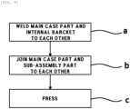
FIG. 8 is a flow chart showing a manufacturing method of a watertight battery lower case of the present disclosure. -
FIG. 9 is a flow chart showing a detailed step of a step of joining a main case part and a sub-assembly part to each other. -
FIG. 10 is a flow chart showing a first embodiment of the manufacturing method of a watertight battery lower case of the present disclosure. -
FIG. 11 is a flow chart showing a second embodiment of the manufacturing method of a watertight battery lower case of the present disclosure. - Hereinafter, the spirit of the present disclosure is described in more detail with reference to the accompanying drawings. Prior to the description, terms and words used in the specification and claims are not to be construed as general or dictionary meanings, and are to be construed as meanings and concepts meeting the spirit of the present disclosure based on a principle in which the inventors may appropriately define the concepts of the terms in order to describe their inventions in the best mode.
- Hereinafter, a basic configuration of a watertight battery
lower case 1000 of the present disclosure is described with reference toFIG. 1 . - As shown in
FIG. 1 , the watertight batterylower case 1000 of the present disclosure may include amain case part 100. Themain case part 100 may be applied to a lower part of a battery module M to protect the battery module M, and have a flat shape. In addition, the watertight batterylower case 1000 of the present disclosure may include aninternal bracket part 200 disposed between one surface of themain case part 100 and the battery module M to support their joining. In addition, the watertight batterylower case 1000 of the present disclosure may include asub-assembly part 300 having one surface in contact with and stacked on the other surface of themain case part 100. - The watertight battery
lower case 1000 of the present disclosure may include afixing part 400 joining and fixing themain case part 100, theinternal bracket part 200, and thesub-assembly part 300 described above to one another. Thefixing part 400 may simultaneously include awelded joint 410 joined by welding and anadhesive joint 420 joined by an adhesive. Here, the adhesive for theadhesive joint 420 may be a structural adhesive such as epoxy. That is, the watertight batterylower case 1000 of the present disclosure may use both of welding and adhesive methods, thereby improving watertight performance and significantly lowering a defect rate by offsetting the pros and cons of each of the welding and adhesive methods. Here, themain case part 100, theinternal bracket part 200, and thesub-assembly part 300 may be required to be joined to one another by sharing a certain joint region together due to other functional problems of a battery, and thefixing part 400 may include thewelded joint 410 and theadhesive joint 420, thus maintaining watertightness of a triple joint area. - To describe the
fixing part 400 in more detail, themain case part 100 and theinternal bracket part 200 may each include welding holes at corresponding positions. Thewelded joint 410 may be welded by simultaneously passing through themain case part 100 and theinternal bracket part 200 via the welding holes. Theadhesive joint 420 may be adhesively joined to themain case part 100 and thesub-assembly part 300 by coating the adhesive therebetween. - Here, in order to further increase an adhesive strength, the
sub-assembly part 300 may have an adhesive storage part engraved in one surface thereof and accommodating the adhesive inside. It is thus possible to increase a coating amount of the adhesive, and increase the adhesive strength by increasing an adhesive depth. In addition, even when the adhesive is joined to the welded joint 410 (and a pore occurs), the over-coated adhesive may penetrate into the pore of thewelded joint 410 to support thewelded joint 410. Its detail is described below. - The
main case part 100, theinternal bracket part 200, and thesub-assembly part 300, which are joined to one another through thewelded joint 410 and theadhesive joint 420 in this way, may be simultaneously pressed to increase the joining strength and watertightness of thecase 1000. Here, the over-coated adhesive may compensate for a defect of thewelded joint 410. Here, a pressing force may be provided in such a way that a pressure is applied by performing additional welding in a non-watertight region. - Hereinafter, a first embodiment of the watertight battery
lower case 1000 of the present disclosure is described with reference toFIG. 2 . - In the first embodiment of the watertight battery
lower case 1000 of the present disclosure shown inFIG. 2 , the adhesive storage part may include a firstadhesive storage groove 311 which is a step recessed to a certain depth in a predetermined adhesive storage region including a region corresponding to the position of the welding hole. Here, the firstadhesive storage groove 311 may be formed in the center of thesub-assembly part 300. The present disclosure may include the firstadhesive storage groove 311, thus increasing the coating amount of the adhesive, and increasing the adhesive depth to thus increase the adhesive strength. - Hereinafter, a second embodiment of the watertight battery
lower case 1000 of the present disclosure is described with reference toFIG. 3 . - In the second embodiment of the watertight battery
lower case 1000 of the present disclosure shown inFIG. 3 , the adhesive storage part may include a secondadhesive storage groove 312 having recesses that are formed in a regular interval in the predetermined adhesive storage region including the region corresponding to the position of the welding hole. Here, the secondadhesive storage groove 312 may be formed in a straight line in an extension direction of thesub-assembly part 300, or may be formed in a checkerboard shape. As the second embodiment of the watertight batterylower case 1000 of the present disclosure is applied, the regions where the adhesive is stored may be separated from each other. Therefore, even if a crack or the defect occurs in any direction, the adhesive may be easily moved during the pressing to compensate for the defect. - Hereinafter, a third embodiment of the watertight battery
lower case 1000 of the present disclosure is described with reference toFIG. 4 . - In the third embodiment of the watertight battery
lower case 1000 of the present disclosure shown inFIG. 4 , when a formation direction of the welding hole and contact surfaces of themain case part 100 and theinternal bracket part 200 are neither perpendicular nor parallel to each other and have a predetermined incline therebetween, the adhesive storage part may include a thirdadhesive storage groove 313 etched stepwise in the predetermined adhesive storage region including the region corresponding to the position of the welding hole. - When the formation direction of the welding hole and the contact surfaces of the
main case part 100 and theinternal bracket part 200 are neither perpendicular nor parallel to each other and have the predetermined incline therebetween, there is a high possibility in which the defect occurs and a joining surface itself is inclined in a severe case. Here, as the third embodiment of the watertight batterylower case 1000 of the present disclosure is applied, the inclined joining surface may be supported by the adhesive, thus securing increased joining stability. - Hereinafter, a fourth embodiment of the watertight battery
lower case 1000 of the present disclosure is described with reference toFIG. 5 . - In the fourth embodiment of the watertight battery
lower case 1000 of the present disclosure shown inFIG. 5 , it is preferable for the adhesive joint 420 to be coated by the adhesive with a greater amount than the maximum amount of the adhesive accommodated in the adhesive storage part including the region corresponding to the position of the welding hole. - In more detail, during a process of the welded joint 410 in a battery pack production line, a welding pressure, a welding current, a welding speed, or the like may be monitored and compared with a predetermined reference value, thereby predicting in advance whether the welded joint 410 has lower density to cause the pore. When a prediction result indicates that the pore is highly likely to occur, the adhesive may be coated with the greater amount than the maximum amount of the adhesive accommodated in the adhesive storage part. Accordingly, the adhesive may be impregnated into the pore to maintain the joining strength of the
case 1000 and increase its watertightness. - Hereinafter, a fifth embodiment of the watertight battery
lower case 1000 of the present disclosure is described with reference toFIG. 6 . - In the fifth embodiment of the watertight battery
lower case 1000 of the present disclosure shown inFIG. 6 , themain case part 100 and theinternal bracket part 200 each include the welding holes at the corresponding positions, and the welded joint 410 may be welded by simultaneously passing through themain case part 100, theinternal bracket part 200, and thesub-assembly part 300 via the welding holes. Here, in order to compensate for the welded joint 410, the adhesive may be coated and cured between theinternal bracket part 200 and the battery module M or coated on the other surface of thesub-assembly part 300. It is thus possible to offset the defect of the welded joint 410. - Furthermore, in the case where the welded joint 410 is predicted to have the lower density, and the pore is thus highly likely to occur, it is possible to maintain the joining strength and increase the watertightness in such a way that the adhesive with the greater amount than its reference amount impregnates into the pore.
- Hereinafter, a sixth embodiment of the watertight battery
lower case 1000 of the present disclosure is described with reference toFIG. 7 . - In the sixth embodiment of the watertight battery
lower case 1000 of the present disclosure shown inFIG. 7 , thesub-assembly part 300 may further include acoating part 314 including a coating material on the other surface. Thecoating part 314 may be a waterproof coating layer. Thesub-assembly part 300 may include thecoating part 314, thereby compensating for the watertightness of its surface. - Hereinafter, a manufacturing method of a watertight battery
lower case 1000 of the present disclosure is described in more detail with reference toFIGS. 8 and9 . - As shown in
FIG. 8 , the manufacturing method of the watertight batterylower case 1000 of the present disclosure may be a method of manufacturing the watertight batterylower case 1000 in which aninternal bracket part 200 is disposed on one surface of amain case part 100, and asub-assembly part 300 is disposed on the other surface of themain case part 100. The method may include: a step (a) of welding themain case part 100 and theinternal bracket part 200 to each other; a step (b) of joining themain case part 100 and thesub-assembly part 300 to each other; and a step (c) of pressing themain case part 100, theinternal bracket part 200, and thesub-assembly part 300 together. Here, in the step (c), a pressure may be applied by performing additional welding in a non-watertight region. Here, it is preferable that themain case part 100, theinternal bracket part 200, and thesub-assembly part 300 are joined to one another by sharing a certain joint region together. - For example, as shown in
FIG. 9 , in the step (b), it is preferable that an adhesive for an adhesive joint 420 is coated between themain case part 100 and thesub-assembly part 300. In addition, the step (b) may include a step (b1) of inspecting the density of a welded joint 410, and it is preferable that the step (b) further includes a step (b2) of coating the adhesive with a greater amount than the maximum amount of the adhesive accommodated in an adhesive storage part of thesub-assembly part 300 when the density of the welded joint 410 in the step (b1) is less than a predetermined reference value. - In the step (b1), during a process of the welded joint 410 in a battery pack production line, a welding pressure, a welding current, a welding speed, or the like may be monitored and compared with the predetermined reference value, thereby predicting in advance whether the welded joint 410 has lower density to cause a pore. In the step (b1), the coating amount of the adhesive may not be adjusted when the density of the welded joint 410 meets the reference value.
- Accordingly, even when the adhesive is joined to the welded joint 410 (and the pore occurs) while performing the step (c) later, the over-coated adhesive may penetrate into the pore of the welded joint 410 to support the welded joint 410. In addition, even if a defect exists in the
sub-assembly part 300 or themain case part 100, the over-coated adhesive may penetrate into the corresponding area and compensate for the defect. - As another example, as shown in
FIG. 10 , in the step (b), thesub-assembly part 300 and themain case part 100 may be welded to each other by the welded joint 410. That is, the steps (a) and (b) may be performed together for thesub-assembly part 300, themain case part 100, and theinternal bracket part 200 to be welded to one another by the welded joint 410. The method may then further include a step (d) following the step (b), the step (d) of coating the adhesive between theinternal bracket part 200 and a battery module M, or coating the adhesive on the other surface of thesub-assembly part 300. The coated adhesive may be cured to protect the welded joint 410 even if the defect occurs in the welded joint 410. - Furthermore, in a case where the welded joint 410 is predicted to have the lower density, and the pore is thus highly likely to occur, it is possible to maintain the joining strength of the
case 1000 and increase its watertightness in such a way that the adhesive with the greater amount than its reference amount impregnates into the pore. - In addition, as shown in
FIG. 11 , the manufacturing method of the watertight batterylower case 1000 of the present disclosure may further include a step (e) of stacking acoating part 314 including a coating material on the other surface of thesub-assembly part 300. The step (e) may follow the step (b). Thecoating part 314 may be a waterproof coating layer. Thecase 1000 may include thecoating part 314, thereby compensating for the watertightness of a surface of thesub-assembly part 300. - As set forth above, the present disclosure may provide the watertight battery lower case with the higher productivity due to the shorter adhesive curing time and the lower welding defect rate by selectively applying the structural adhesive to some joint layers of the watertight battery case and welding the other joint layers to each other, and the manufacturing method thereof.
- The spirit of the present disclosure should not be limited to the embodiments described above. The present disclosure may be applied to various fields and may be variously modified by those skilled in the art without departing from the scope of the present disclosure claimed in the claims. Therefore, it is obvious to those skilled in the art that these alterations and modifications fall within the scope of the present disclosure.
Claims (15)
- A watertight battery lower case comprising:a main case part applied to a lower part of a battery module to protect the battery module, and having a flat shape;an internal bracket part disposed between one surface of the main case part and the battery module to support their joining;a sub-assembly part having one surface in contact with and stacked on another surface of the main case part; anda fixing part joining and fixing the main case part, the internal bracket part, and the sub-assembly part to one another,wherein the fixing part simultaneously includes a welded joint joined by welding and an adhesive joint joined by an adhesive, andthe main case part, the internal bracket part, and the sub-assembly part are joined to one another by sharing a certain joint region together.
- The case of claim 1, wherein the main case part and the internal bracket part each include welding holes at corresponding positions,the welded joint is formed by simultaneously passing through the main case part and the internal bracket part via the welding holes,the adhesive joint is formed by adhesively joining the main case part to the sub-assembly part by coating the adhesive therebetween, andthe sub-assembly part has an adhesive storage part engraved therein and accommodating the adhesive inside.
- The case of claim 2, wherein the adhesive storage part includes a first adhesive storage groove which is a step recessed to a certain depth in a predetermined adhesive storage region including a region overlapping a position of the welding hole.
- The case of claim 2 or 3, wherein the adhesive storage part includes a second adhesive storage groove having recesses that are formed in a regular interval in a predetermined adhesive storage region including a region overlapping a position of the welding hole.
- The case of any one of claims 2 to 4, wherein when a formation direction of the welding hole and contact surfaces of the main case part and the internal bracket part are neither perpendicular nor parallel to each other and have a predetermined incline therebetween,
the adhesive storage part includes a third adhesive storage groove etched stepwise in a predetermined adhesive storage region including a region overlapping a position of the welding hole. - The case of any one of claims 2 to 5, wherein when the density of the welded joint is less than a predetermined reference value, the adhesive joint is coated by the adhesive with a greater amount than a maximum amount of the adhesive accommodated in the adhesive storage part including a region overlapping a position of the welding hole.
- The case of any one of claims 1 to 6, wherein the main case part and the internal bracket part each include welding holes at corresponding positions, and
the welded joint is formed by simultaneously passing through the main case part, the internal bracket part, and the sub-assembly part via the welding holes. - The case of claim 7, wherein for the adhesive joint, the adhesive is coated between the internal bracket part and the battery module or coated on an outer surface of the sub-assembly part.
- The case of claim 7 or 8, wherein the sub-assembly part further includes a coating part including a coating material on an outer surface of the sub-assembly part.
- A manufacturing method of a watertight battery lower case in which an internal bracket part is disposed on one surface of a main case part, and a sub-assembly part is disposed on another surface of the main case part, the method comprising:a step (a) of welding the main case part and the internal bracket part to each other;a step (b) of joining the main case part and the sub-assembly part to each other; anda step (c) of pressing the main case part, the internal bracket part, and the sub-assembly part together,wherein the main case part, the internal bracket part, and the sub-assembly part are joined to one another by sharing a certain joint region together.
- The method of claim 10, wherein the step (b) includes forming an adhesive joint by coating an adhesive between the main case part and the sub-assembly part.
- The method of claim 11, wherein the step (b) includes a step (b1) of inspecting the density of a welded joint between the main case part and the internal bracket part, and
the step (b) further includes a step (b2) of coating the adhesive with a greater amount than a maximum amount of the adhesive accommodated in an adhesive storage part of the sub-assembly part when the density of the welded joint in the step (b1) is less than a predetermined reference value. - The method of any one of claims 10 to 12, wherein in the step (b), the sub-assembly part, the main case part, and the internal bracket part are welded to one another by a welded joint.
- The method of claim 13, further comprising, following the step (b), a step (d) of coating an adhesive between the internal bracket part and a battery module, or coating the adhesive on an outer surface of the sub-assembly part.
- The method of any one of claims 10 to 14, further comprising, following the step (b), a step (e) of stacking a coating part including a coating material on an outer surface of the sub-assembly part.
Applications Claiming Priority (1)
| Application Number | Priority Date | Filing Date | Title |
|---|---|---|---|
| KR1020230074703A KR20240175070A (en) | 2023-06-12 | 2023-06-12 | Watertight battery lower case and manufacturing method thereof |
Publications (1)
| Publication Number | Publication Date |
|---|---|
| EP4478506A1 true EP4478506A1 (en) | 2024-12-18 |
Family
ID=91022599
Family Applications (1)
| Application Number | Title | Priority Date | Filing Date |
|---|---|---|---|
| EP24173976.2A Pending EP4478506A1 (en) | 2023-06-12 | 2024-05-03 | Watertight battery lower case and manufacturing method thereof |
Country Status (3)
| Country | Link |
|---|---|
| US (1) | US20240413453A1 (en) |
| EP (1) | EP4478506A1 (en) |
| KR (1) | KR20240175070A (en) |
Citations (3)
| Publication number | Priority date | Publication date | Assignee | Title |
|---|---|---|---|---|
| EP3855525A1 (en) * | 2018-09-20 | 2021-07-28 | LG Hausys, Ltd. | Battery case for electric car |
| US20230006297A1 (en) * | 2019-11-29 | 2023-01-05 | Kirchhoff Automotive Deutschland Gmbh | Battery Housing For A Vehicle Driven By An Electric Motor |
| EP4145604A1 (en) * | 2020-06-09 | 2023-03-08 | BYD Company Limited | Battery pack and vehicle |
Family Cites Families (1)
| Publication number | Priority date | Publication date | Assignee | Title |
|---|---|---|---|---|
| KR102098495B1 (en) | 2018-09-18 | 2020-04-07 | 주식회사 포스코 | Battery case |
-
2023
- 2023-06-12 KR KR1020230074703A patent/KR20240175070A/en active Pending
-
2024
- 2024-02-27 US US18/588,367 patent/US20240413453A1/en active Pending
- 2024-05-03 EP EP24173976.2A patent/EP4478506A1/en active Pending
Patent Citations (3)
| Publication number | Priority date | Publication date | Assignee | Title |
|---|---|---|---|---|
| EP3855525A1 (en) * | 2018-09-20 | 2021-07-28 | LG Hausys, Ltd. | Battery case for electric car |
| US20230006297A1 (en) * | 2019-11-29 | 2023-01-05 | Kirchhoff Automotive Deutschland Gmbh | Battery Housing For A Vehicle Driven By An Electric Motor |
| EP4145604A1 (en) * | 2020-06-09 | 2023-03-08 | BYD Company Limited | Battery pack and vehicle |
Also Published As
| Publication number | Publication date |
|---|---|
| KR20240175070A (en) | 2024-12-19 |
| US20240413453A1 (en) | 2024-12-12 |
Similar Documents
| Publication | Publication Date | Title |
|---|---|---|
| EP2375469B1 (en) | Secondary battery and a fabrication method thereof | |
| KR101287734B1 (en) | Connection plate for cell terminal and method for manufacturing connection plate for cell terminal | |
| US20100258538A1 (en) | Method of producing welded structure and method of producing battery | |
| US11923554B2 (en) | Extruded hollow plate, battery box bottom plate, battery casing, and electric vehicle | |
| TW201103791A (en) | Method for reinforcing structure for railway rolling stock and structure for railway rolling stock | |
| CN109768199B (en) | Method for manufacturing lower shell of battery cladding | |
| KR20150017699A (en) | Lithium ion cell outer package material and method for manufacturing lithium ion cell in which lithium ion cell outer package material is used | |
| KR102649923B1 (en) | Method for manufacturing pouch type secondary battery | |
| CN109822207B (en) | How to make lower case of battery pack | |
| US20180197833A1 (en) | Semiconductor device and manufacturing method of semiconductor device | |
| JP2015088729A (en) | Substrate structure and method for manufacturing the same | |
| KR20150120045A (en) | End plate for fuel cell | |
| KR102192963B1 (en) | Cell and method for manufacturing such a cell | |
| JP2010097770A (en) | Battery casing, secondary battery and method for manufacturing secondary battery | |
| JP2014059954A (en) | Prismatic battery can and manufacturing method therefor | |
| US20240413453A1 (en) | Watertight battery lower case and manufacturing method thereof | |
| JP2006135018A (en) | Reactor core | |
| KR101845855B1 (en) | Terminal-equipped battery case lid and sealed battery | |
| US11757136B2 (en) | Power storage module and manufacturing method of power storage module | |
| JP2019119378A (en) | Solar array panel, repair method thereof | |
| CN109689265A (en) | Multi-layer part and its manufacturing method | |
| JP7517181B2 (en) | Laminated electrode body, resin-fixed laminated electrode body, and all-solid-state battery | |
| US20160243791A1 (en) | Bonded assembly provided with a intermediate deformation layer with variable flexibility | |
| JP5569261B2 (en) | Lead member and lead member manufacturing method | |
| CN111143993A (en) | Glue joint repairing method for main bearing laminated board |
Legal Events
| Date | Code | Title | Description |
|---|---|---|---|
| PUAI | Public reference made under article 153(3) epc to a published international application that has entered the european phase |
Free format text: ORIGINAL CODE: 0009012 |
|
| STAA | Information on the status of an ep patent application or granted ep patent |
Free format text: STATUS: THE APPLICATION HAS BEEN PUBLISHED |
|
| AK | Designated contracting states |
Kind code of ref document: A1 Designated state(s): AL AT BE BG CH CY CZ DE DK EE ES FI FR GB GR HR HU IE IS IT LI LT LU LV MC ME MK MT NL NO PL PT RO RS SE SI SK SM TR |
|
| STAA | Information on the status of an ep patent application or granted ep patent |
Free format text: STATUS: REQUEST FOR EXAMINATION WAS MADE |
|
| 17P | Request for examination filed |
Effective date: 20250616 |
|
| STAA | Information on the status of an ep patent application or granted ep patent |
Free format text: STATUS: EXAMINATION IS IN PROGRESS |
|
| 17Q | First examination report despatched |
Effective date: 20250827 |
|
| GRAP | Despatch of communication of intention to grant a patent |
Free format text: ORIGINAL CODE: EPIDOSNIGR1 |
|
| STAA | Information on the status of an ep patent application or granted ep patent |
Free format text: STATUS: GRANT OF PATENT IS INTENDED |
|
| INTG | Intention to grant announced |
Effective date: 20260429 |