EP4478496A1 - Pole post, top cap assembly, and cell - Google Patents
Pole post, top cap assembly, and cell Download PDFInfo
- Publication number
- EP4478496A1 EP4478496A1 EP24181147.0A EP24181147A EP4478496A1 EP 4478496 A1 EP4478496 A1 EP 4478496A1 EP 24181147 A EP24181147 A EP 24181147A EP 4478496 A1 EP4478496 A1 EP 4478496A1
- Authority
- EP
- European Patent Office
- Prior art keywords
- post
- metal
- metal base
- groove
- protrusion portion
- Prior art date
- Legal status (The legal status is an assumption and is not a legal conclusion. Google has not performed a legal analysis and makes no representation as to the accuracy of the status listed.)
- Pending
Links
Images


Classifications
-
- H—ELECTRICITY
- H01—ELECTRIC ELEMENTS
- H01M—PROCESSES OR MEANS, e.g. BATTERIES, FOR THE DIRECT CONVERSION OF CHEMICAL ENERGY INTO ELECTRICAL ENERGY
- H01M50/00—Constructional details or processes of manufacture of the non-active parts of electrochemical cells other than fuel cells, e.g. hybrid cells
- H01M50/50—Current conducting connections for cells or batteries
- H01M50/543—Terminals
- H01M50/552—Terminals characterised by their shape
- H01M50/553—Terminals adapted for prismatic, pouch or rectangular cells
-
- H—ELECTRICITY
- H01—ELECTRIC ELEMENTS
- H01M—PROCESSES OR MEANS, e.g. BATTERIES, FOR THE DIRECT CONVERSION OF CHEMICAL ENERGY INTO ELECTRICAL ENERGY
- H01M50/00—Constructional details or processes of manufacture of the non-active parts of electrochemical cells other than fuel cells, e.g. hybrid cells
- H01M50/10—Primary casings; Jackets or wrappings
- H01M50/102—Primary casings; Jackets or wrappings characterised by their shape or physical structure
- H01M50/103—Primary casings; Jackets or wrappings characterised by their shape or physical structure prismatic or rectangular
-
- H—ELECTRICITY
- H01—ELECTRIC ELEMENTS
- H01M—PROCESSES OR MEANS, e.g. BATTERIES, FOR THE DIRECT CONVERSION OF CHEMICAL ENERGY INTO ELECTRICAL ENERGY
- H01M50/00—Constructional details or processes of manufacture of the non-active parts of electrochemical cells other than fuel cells, e.g. hybrid cells
- H01M50/10—Primary casings; Jackets or wrappings
- H01M50/147—Lids or covers
- H01M50/148—Lids or covers characterised by their shape
- H01M50/15—Lids or covers characterised by their shape for prismatic or rectangular cells
-
- H—ELECTRICITY
- H01—ELECTRIC ELEMENTS
- H01M—PROCESSES OR MEANS, e.g. BATTERIES, FOR THE DIRECT CONVERSION OF CHEMICAL ENERGY INTO ELECTRICAL ENERGY
- H01M50/00—Constructional details or processes of manufacture of the non-active parts of electrochemical cells other than fuel cells, e.g. hybrid cells
- H01M50/10—Primary casings; Jackets or wrappings
- H01M50/172—Arrangements of electric connectors penetrating the casing
- H01M50/174—Arrangements of electric connectors penetrating the casing adapted for the shape of the cells
- H01M50/176—Arrangements of electric connectors penetrating the casing adapted for the shape of the cells for prismatic or rectangular cells
-
- H—ELECTRICITY
- H01—ELECTRIC ELEMENTS
- H01M—PROCESSES OR MEANS, e.g. BATTERIES, FOR THE DIRECT CONVERSION OF CHEMICAL ENERGY INTO ELECTRICAL ENERGY
- H01M50/00—Constructional details or processes of manufacture of the non-active parts of electrochemical cells other than fuel cells, e.g. hybrid cells
- H01M50/50—Current conducting connections for cells or batteries
- H01M50/528—Fixed electrical connections, i.e. not intended for disconnection
-
- H—ELECTRICITY
- H01—ELECTRIC ELEMENTS
- H01M—PROCESSES OR MEANS, e.g. BATTERIES, FOR THE DIRECT CONVERSION OF CHEMICAL ENERGY INTO ELECTRICAL ENERGY
- H01M50/00—Constructional details or processes of manufacture of the non-active parts of electrochemical cells other than fuel cells, e.g. hybrid cells
- H01M50/50—Current conducting connections for cells or batteries
- H01M50/543—Terminals
- H01M50/552—Terminals characterised by their shape
- H01M50/553—Terminals adapted for prismatic, pouch or rectangular cells
- H01M50/557—Plate-shaped terminals
-
- H—ELECTRICITY
- H01—ELECTRIC ELEMENTS
- H01M—PROCESSES OR MEANS, e.g. BATTERIES, FOR THE DIRECT CONVERSION OF CHEMICAL ENERGY INTO ELECTRICAL ENERGY
- H01M50/00—Constructional details or processes of manufacture of the non-active parts of electrochemical cells other than fuel cells, e.g. hybrid cells
- H01M50/50—Current conducting connections for cells or batteries
- H01M50/543—Terminals
- H01M50/552—Terminals characterised by their shape
- H01M50/561—Hollow metallic terminals, e.g. terminal bushings
-
- H—ELECTRICITY
- H01—ELECTRIC ELEMENTS
- H01M—PROCESSES OR MEANS, e.g. BATTERIES, FOR THE DIRECT CONVERSION OF CHEMICAL ENERGY INTO ELECTRICAL ENERGY
- H01M50/00—Constructional details or processes of manufacture of the non-active parts of electrochemical cells other than fuel cells, e.g. hybrid cells
- H01M50/50—Current conducting connections for cells or batteries
- H01M50/543—Terminals
- H01M50/562—Terminals characterised by the material
-
- H—ELECTRICITY
- H01—ELECTRIC ELEMENTS
- H01M—PROCESSES OR MEANS, e.g. BATTERIES, FOR THE DIRECT CONVERSION OF CHEMICAL ENERGY INTO ELECTRICAL ENERGY
- H01M50/00—Constructional details or processes of manufacture of the non-active parts of electrochemical cells other than fuel cells, e.g. hybrid cells
- H01M50/50—Current conducting connections for cells or batteries
- H01M50/543—Terminals
- H01M50/564—Terminals characterised by their manufacturing process
-
- H—ELECTRICITY
- H01—ELECTRIC ELEMENTS
- H01M—PROCESSES OR MEANS, e.g. BATTERIES, FOR THE DIRECT CONVERSION OF CHEMICAL ENERGY INTO ELECTRICAL ENERGY
- H01M50/00—Constructional details or processes of manufacture of the non-active parts of electrochemical cells other than fuel cells, e.g. hybrid cells
- H01M50/50—Current conducting connections for cells or batteries
- H01M50/543—Terminals
- H01M50/564—Terminals characterised by their manufacturing process
- H01M50/567—Terminals characterised by their manufacturing process by fixing means, e.g. screws, rivets or bolts
-
- Y—GENERAL TAGGING OF NEW TECHNOLOGICAL DEVELOPMENTS; GENERAL TAGGING OF CROSS-SECTIONAL TECHNOLOGIES SPANNING OVER SEVERAL SECTIONS OF THE IPC; TECHNICAL SUBJECTS COVERED BY FORMER USPC CROSS-REFERENCE ART COLLECTIONS [XRACs] AND DIGESTS
- Y02—TECHNOLOGIES OR APPLICATIONS FOR MITIGATION OR ADAPTATION AGAINST CLIMATE CHANGE
- Y02E—REDUCTION OF GREENHOUSE GAS [GHG] EMISSIONS, RELATED TO ENERGY GENERATION, TRANSMISSION OR DISTRIBUTION
- Y02E60/00—Enabling technologies; Technologies with a potential or indirect contribution to GHG emissions mitigation
- Y02E60/10—Energy storage using batteries
Definitions
- the disclosure relates to the field of battery, and in particular, to a pole post, a top cap assembly, and a cell.
- a pole post of a cell is an important component that connects an electrode assembly inside the cell to an external circuit.
- a combination of two different metals is generally used to prepare the pole post of the negative electrode.
- an upper metal block and a lower metal block are fixedly connected to each other to form metal composite blanks by the friction welding process, and the metal composite blanks are cut and processed by the computer numerical control (CNC), so as to form the pole post and ensure the dimension of the pole post, thereby forming the pole post with two different metals.
- CNC computer numerical control
- the disclosure provides a pole post, a top cap assembly, and a cell to solve the above-mentioned technical problem.
- the disclosure provides a pole post, including:
- the disclosure further provides a top cap assembly including a cap plate and the pole post as discussed above, and the pole post is disposed on the cap plate.
- the disclosure further provides a cell including a housing, an electrode assembly, and the top cap assembly as discussed above.
- the electrode assembly is disposed in an internal cavity of the housing, the cap plate is connected to the housing, and the electrode assembly is electrically connected to the pole post.
- a pole post provided in the disclosure can be formed by a cold heading process. Compared to traditional pole posts formed by the friction welding process, the cold heading process improves the efficiency of producing the pole post, effectively reduces the waste of materials, and better controls the production cost. Moreover, on the basis of meeting the requirement for dimension, by forming a first groove in a metal post away from the metal base by cold heading, materials originally located at the first groove can move towards other positions of a metal post, thereby increasing the height of the metal post, saving the materials for the metal post, and reducing cost of producing the metal post.
- the disclosure can reduce the production cost of the electrode assembly by setting the above-mentioned pole post in the cell.
- connection and “fixed” should be understood broadly, unless otherwise specified.
- it can be a fixed connection, a detachable connection, or an integral connection; alternatively, it can be a mechanical connection or an electrical connection; and alternatively, it can be a direct connection, an indirect connection through an intermediate medium, an internal connection of two elements, or an interaction relationship between two elements.
- specific meanings of the above terms in the disclosure may be understood based on specific application scenarios.
- a first feature is disposed “on”, “above”, “under”, or “below” a second feature indicates that the first feature is in direct contact with the second feature, or in indirect contact with the second feature through other features between them, unless otherwise specified.
- the expression that the first feature is disposed “on” or “above” the second feature indicates that the first feature is directly above and diagonally above the second feature, or simply indicates that the first feature is horizontally higher than the second feature.
- the expression that the first feature is disposed “under” or “below” the second feature indicates that the first feature is directly below and diagonally below the second feature, or simply indicates that the horizontal height of the first feature is less than that of the second feature.
- the top cap assembly includes a cap plate 200, a briquetting 300, a connecting sheet 400, and the pole post 100.
- a mounting hole 310 is provided in the briquetting 300.
- the pole post 100 passes through the cap plate 200 and is matched with the mounting hole 310.
- the pole post 100 and the briquetting 300 are fixed by laser welding.
- the briquetting 300 and the pole post 100 abut against two sides of the cap plate 200, respectively.
- An end of the pole post 100 is connected to an external circuit of the battery, and another end of the pole post 100 is connected to the connecting sheet 400 by welding.
- the connecting sheet 400 is connected to an electrode assembly in the battery, so as to achieve the function of charging and discharging.
- the structure of the cap plate 200 is clear to those of ordinary skill in the art and is not limited herein.
- the pole post 100 includes a metal base 110 and a metal post 120.
- the metal post 120 is disposed on a top of the metal base 110. Materials of the metal post 120 and the metal base 110 are different.
- a bottom of the metal post 120 is connected to a top of the metal base 110.
- a surface of the metal post 120 away from the metal base 110 is provided with a first groove 1201.
- the pole post 100 is formed by a copper-aluminum composite plate by a cold heading process.
- the cold heading process improves the efficiency of producing the pole post 100, effectively reduces the waste of materials caused by the cutting process, and better controls the production cost.
- the cold heading process enables the copper layer and the aluminum layer to be firmly bonded together, reducing the fracture risk of the pole post 100 and improving the reliability of the pole post 100.
- the pole post 100 includes the metal base 110 and the metal post 120 coaxially connected to each other, and peripheral dimensions of the metal base 110 and the metal post 120 decrease sequentially.
- the metal base 110 is made of copper.
- the metal post 120 is made of aluminum.
- An end surface of the metal base 110 is connected to an end surface of the metal post 120 to form a joint surface 1001, which is a contact surface between the metal post 120 and the metal base 110.
- the metal base 110 and the metal post 120 are both cylindrical structures, and an outer diameter of the metal base 110 is greater than an outer diameter of the metal post 120, so that the metal base 110 abuts against a lower surface of the cap plate 200 to achieve a limiting effect after the metal post 120 passes through the cap plate 200.
- the first groove 1201 is formed in the metal post 120 away from the metal base 110 by the cold heading process.
- the blanks undergo equal volume deformation by cold extrusion during the cold heading process, including forming the first groove 1201 on the top of the metal post 120 by the cold heading process, and enabling the material originally located at the first groove 1201 to move to other positions of the metal post 120. Because the diameter of the metal post 120 remains unchanged, the height of the metal post 120 increases during the cold heading process. While meeting the requirement for the dimensions, the process saves materials for producing the metal post 120, and reduces the cost of producing the metal post 120. Moreover, the setting of the first groove 1201 can reduce the weight of the top cap assembly of the battery to achieve a lightweight design.
- a bottom surface 1202 of the first groove 1201 is higher than a bottom surface of the metal post 120, that is, the bottom surface 1202 of the first groove 1201 is higher than the joint surface 1001 between the metal post 120 and the metal base 110.
- the first groove 1201 can be formed only in the metal post 120 (an aluminum layer) by cold heading without damaging the joint surface 1001 (a copper-aluminum joint surface) between the metal post 120 and the metal base 110, ensuring that the metal base 110 (the copper layer) and the metal post 120 (the aluminum layer) are firmly bonded together, reducing the fracture risk of the pole post 100, thereby improving the structural strength of the pole post 100.
- a distance K between the bottom surface 1202 of the first groove 1201 and the bottom surface of the metal post 120 (the joint surface 1001 between the metal post 120 and the metal base 110) in an axial direction is greater than 0.5 mm and less than 2.5 mm.
- the distance K between the bottom surface 1202 of the first groove 1201 and the joint surface 1001 in the axial direction can be 0.6 mm, 0.8 mm, 1.0 mm, 1.2 mm, 1.4 mm, 1.6 mm, 1.8 mm, 2.0 mm, 2.2 mm, or 2.4 mm.
- a minimum distance W between a sidewall 1203 of the first groove 1201 and an outer sidewall 1204 of the metal post 120 is greater than or equal to 1 mm.
- the minimum distance W may be a minimum wall thickness of the metal post 120, and can be 1 mm, 2 mm, 3 mm, 4 mm, 5 mm, 6 mm, or 7 mm.
- the outer sidewall 1204 of the metal post 120 is inclined relative to the axis of the metal post 120.
- An inclination direction and an inclination angle of an inner sidewall of the mounting hole 310 of the briquetting 300 are respectively the same as an inclination direction and an inclination angle of the outer sidewall 1204 of the metal post 120, and the outer sidewall 1204 of the metal post 120 is matched with the inner sidewall of the mounting hole 310.
- the outer sidewall 1204 of the metal post 120 is inclined towards the interior of the metal post 120 from bottom to top.
- the outer sidewall 1204 of the metal post 120 can be inclined towards a direction close to the first groove 1201 from bottom to top, as long as the inner sidewall of the mounting hole 310 is set to have the same inclination direction and the same inclination angle as the outer sidewall 1204 of the metal post 120. That is, the outer sidewall 1204 of the metal post 120 and the inner sidewall of the mounting hole 310 are both inclined surfaces, so that the metal post 120 is matched with the mounting hole 310 through the inclined surface.
- the setting of the inclined surface prevents laser from irradiating and burning lower plastic component of the cap plate 200 during the laser welding process.
- the pole post 100 can be interlocked with the briquetting 300 through the inclined surface at the joint surface 1001, thereby improving the structural strength of the cap plate 200 of the battery.
- an inclination angle ⁇ between the outer sidewall 1204 of the metal post 120 and the axis of the metal post 120 is greater than 0° and less than or equal to 3°, for example, 1°, 2°, or 3°.
- the peripheral dimensions of the metal base 110 and the metal post 120 decrease sequentially.
- a side of the metal base 110 close to the metal post 120 is provided with a boss 113.
- a peripheral dimension of the boss 113 is less than the peripheral dimension of the metal base 110 and substantially the same as a peripheral dimension of the bottom of the metal post 120.
- the boss 113 is connected to the metal post 120, and a connecting end surface between the boss 113 and the metal post 120 is the joint surface 1001 (the copper-aluminum joint surface).
- metal base 110 When forming the metal base 110 by the cold heading process, aluminum used to form the metal post 120 and part copper used to form the boss 113 can be precisely limited by a sidewall of a concave cavity of a concave mold, and other copper outside the concave mold will be pressed by a protrusion mold to form the metal base 110. Therefore, the setting of the boss 113 limits the flow of aluminum, avoiding the dimension of the metal post 120 being too small caused by insufficient volume of aluminum. Moreover, it also makes the metal base 110 only form as the copper layer without damaging the copper-aluminum joint surface, thereby improving the structural strength of the pole post 100 and reducing the fracture risk of the pole post 100.
- the boss 113 has a height h greater than 0.3 mm and less than 1.2 mm. That is, a distance h between a top surface of the boss 113 and a flange 111 in an axial direction is greater than 0.3 mm and less than 1.2 mm.
- the height h of the boss 113 can be 0.4 mm, 0.5 mm, 0.6 mm, 0.7 mm, 0.8 mm, 0.9 mm, 1.0 mm, or 1.1 mm.
- a surface of the metal base 110 away from the metal post 120 is provided with a second groove 1101. Apart of the bottom surface of the metal post 120 is located between the first groove 1201 and the second groove 1101. Apart of the metal base 110 extends outside a peripheral surface of the metal post 120 in a radial direction.
- the material originally located at the second groove 1101 of the metal base 110 extends radically outwards during the cold heading process. Because the volume is not changed after the metal base 110 deforms during the cold heading process, the diameter of the metal base 110 can be enlarged, and the dimension around the second groove 1101 can be enlarged accordingly to meet the requirement for the dimension.
- a longitudinal sectional surface of the second groove 1101 is in an arc shape, and an angle ⁇ between a circumferential sidewall of the second groove 1101 and a horizontal plane is greater than or equal to 15° and less than or equal to 60°.
- the angle ⁇ may be 15°, 20°, 25°, 30°, or 40°.
- the metal base 110 has a larger diameter, providing better fluidity for copper used in the copper-aluminum composite plate, making the bottom of the pole post 100 less prone to fracture, thereby improving the structural strength of the pole post 100.
- a shape of a circumferential sectional surface of the second groove 1101 may be, but not limited to, circular, square, elliptical, or other irregular shapes, and can be flexibly adapted according to the requirements without special limitations.
- the flange 111 is formed at a peripheral surface of the metal base 110.
- the flange 111 protrudes from an edge of the metal post 120 in a direction away from an axis of the metal base 110. That is, the flange 111 extends along the direction away from the axis of the metal base 110 and protrudes from the edge of the metal post 120.
- a surface of the flange 111 away from the metal post 120 is provided with a first step 112
- a stepped hole 410 is provided in the connecting sheet 400, and the first step 112 is configured to be matched with the stepped hole 410.
- the setting of the first step 112 makes the metal base 110 have two different outer diameters, and the stepped hole 410 includes two holes with different diameters.
- the fitting of the two stepped surfaces can block the gap between a part of the metal base 110 having a smaller outer diameter and an inner sidewall of the stepped hole 410, avoiding the heat generated by welding from being transmitted to the lower plastic component of the cap plate 200 through the gap.
- the joint surface 1001 between the metal base 110 and the metal post 120 is a flat surface.
- the second groove 1101 is disposed corresponding to the first groove 1201.
- the joint surface 1001 between the metal base 110 and the metal post 120 undergoes a downward force when forming the first groove 1201, and undergoes an upward force when forming the second groove 1101. That is, the joint surface 1001 between the metal base 110 and the metal post 120 undergoes two forces from opposite directions. The two forces cancel out, making the joint surface 1001 between the metal base 110 and the metal post 120 be the flat surface.
- the embodiment 2 of the disclosure is similar to the embodiment 1, and the part not described in detail can refer to the embodiment 1.
- the distance H, a volume V of the first groove 1201, and an area S of an orthogonal projection of the metal post 120 on the metal base 110 satisfy the following relationship: 3 mm ⁇ H-V/S ⁇ 10 mm.
- the above relationship ensures that the dimension of the pole post 100 can meet the requirement for the cold heading process, avoiding the waste of raw materials for producing the pole post 100, and reducing the production cost of the pole post 100.
- the second groove 1101 is disposed at the bottom of the metal base 110.
- the metal post 120 is disposed on the top of the metal base 110.
- the bottom of the metal post 120 is connected to at least a part of the top of the metal base 110.
- the distance H, the volume V of the first groove 1201, and the area S of the orthogonal projection of the metal post 120 on the metal base 110 satisfy the following relationship: 3 mm ⁇ H-V/S ⁇ 10 mm.
- H 0 represents a distance between an initial top surface of the metal post 120 and an initial bottom surface of the metal post 120 before the cold heading process, that is, an initial thickness of the metal post 120; and H represents the distance between the top surface of the metal post 120 and the plane F where the bottom surface of the metal post 120 between the first groove 1201 and the second groove 1101 is located after the cold heading process, that is, a molding thickness of the metal post 120.
- the metal post 120 originally positioned at the first groove 1201 extends to an unrestricted position due to the equal volume deformation of the metal post 120, which increases the height of the metal post 120. Therefore, the distance H between the top surface of the metal post 120 and the plane F where the bottom surface of the metal post 120 between the first groove 1201 and the second groove 1101 is located after cold heading is positively correlated with the volume V of the first groove 1201.
- the first groove 1201 on the metal post 120 is formed by extrusion, increasing the distance H between the top surface of the metal post 120 and the plane F where the bottom surface of the metal post 120 between the first groove 1201 and the second groove 1101 is located, that is, increasing the thickness (height) of the metal post 120, so that the height of the metal post 120 meets the requirement for the height of the pole post 100 in the cell.
- the pole post 100 provided in some embodiments can be prepared by the cold heading process.
- the cold heading process has less requirements for the process, has stronger operability, and needs lower processing temperature.
- it is not easy to cause thermal stress of metal avoiding the deformation caused by thermal stress on the metal base 110 and the metal post 120, avoiding cracks and even fractures on the welding surface of the metal base 110 and the metal post 120 caused by high temperature, thereby improving the reliability and safety of the pole post 100.
- the second groove 1101 is disposed in the metal base 110 away from the metal post 120, and disposed corresponding to the first groove 1201, so that the metal post 120 undergoes an extrusion force pointing from the metal base 110 to the metal post 120 during the cold heading process, which increases the bonding strength between the metal base 110 and the metal post 120 at the joint surface 1001, strengthens the bonding strength between the metal base 110 and the metal post 120, and improves the reliability of the pole post 100.
- the joint surface 1001 between the metal post 120 and the metal base 110 is recessed towards the metal base 110, which is formed when stamping the first groove 1201.
- the joint surface 1001 may be uneven.
- the contact surface between the metal post 120 and the metal base 110 is formed by fitting a concave surface with a convex surface, which improves the bonding strength between the metal post 120 and the metal base 110, ensures that the copper layer and the aluminum layer are firmly bonded, reduces the fracture risk of the pole post 100, and improves the structural strength of the pole post 100.
- a part of the bottom surface of the metal post 120 is located between the first groove 1201 and the second groove 1101, a surface of the metal post 120 close to the metal base 110 is provided with a first protrusion portion 1211 protruding towards the metal base 110.
- An orthographic projection of the first protrusion portion 1211 on a plane where the metal base 110 is located surrounds an orthographic projection of the bottom surface 1202 of the first groove 1201 on the plane where the metal base 110 is located.
- the first protrusion portion 1211 extends towards the metal base 110.
- a surface of the metal base 110 close to the metal post 120 is provided with a first concave portion 1141 matched with the first protrusion portion 1211.
- a top surface of the first concave portion 1141 is in contact with a bottom surface of the first protrusion portion 1211.
- the joint surface 1001 between the first concave portion 1141 and the first protrusion portion 1211 is a curved surface.
- the top surface of the metal base 110 is in direct contact with the bottom surface of the metal post 120.
- the top surface of the metal base 110 is provided with the first concave portion 1141 matched with the first protrusion portion 1211 of the metal post 120. That is, the first concave portion 1141 of the metal base 110 is in contact with the first protrusion portion 1211 of the metal post 120, which increases a contact area between the metal base 110 and the metal post 120, strengthens the bonding strength between the metal base 110 and the metal post 120, improves the reliability of the pole post 100, and effectively improves the fracture problem of the pole post 100.
- a part of the joint surface 1001 between the metal base 110 and the metal post 120 is a curved surface, and an orthogonal projection of the curved surface on the plane where the metal base 110 is located surrounds an orthogonal projection of the second groove 1101 on the plane where the metal base 110 is located.
- the first groove 1201 and the second groove 1101 are configured to be matched with an external cold heading equipment, so that the cold heading equipment can apply an extrusion force on the metal base 110 and the metal post 120, achieving the equal volume deformation of the metal base 110 and the metal post 120.
- At least a part of the joint surface 1001 between the metal base 110 and the metal post 120 surrounding the second groove 1101 is a curved surface, that is, a part of the joint surface 1001 between the metal base 110 and the metal post 120 is a curved surface, which increases the contact area between the metal base 110 and the metal post 120, forms an interlocking structure consisting of the metal base 110 and the metal post 120, strengthens the bonding strength between the metal base 110 and the metal post 120, and avoids the fracture risk of the pole post 100.
- the metal base 110 and the metal post 120 have different hardness.
- the hardness of the metal base 110 is greater than the hardness of the metal post 120.
- the number of the first groove 1201 and the second groove 1101 are one, and the central axis of the first groove 1201 and the central axis of the second groove 1101 are in the same axis.
- the number of the second grooves 1101 is two or more than two.
- a longitudinal sectional surface of a part of the metal post 120 and/or the metal base 110 overlapping with the curved surface has a stretch line 122 that is a curve.
- a protruding direction of the stretch line 122 and a protruding direction of the first protrusion portion 1211 are the same.
- both of a part of the metal post 120 overlapping with the curved surface and a part of the metal base 110 overlapping with the curved surface have the stretch line 122.
- the metal structural grains in the metal post 120 and the metal base 110 are arranged along the stretch line 122, and the atomic arrangement at the interfaces (grain boundary) among the metal structural grains is irregular, which improves the shaping resistance of the metal base 110 and the metal post 120, so that the metal base 110 and the metal post 120 have higher strength and hardness, and the pole post 100 has stronger impact resistance and compression resistance after being formed by the cold heading process.
- the method for observing the stretch line 122 is as follows: cutting the pole post 100 along the axis of the pole post 100, immersing it in acidic liquid for a period of time, and observing the sectional surface of the pole post 100. Because the grain boundary has higher free energy, the grain boundary is susceptible to the corrosion of acidic solutions to form channels, showing the stretch line 122 formed by the arrangement of polygonal grains.
- the pole post 100 is a copper-aluminum composite member.
- the metal base 110 is the copper layer of a copper-aluminum composite member, and the metal post 120 is an aluminum layer of the copper-aluminum composite member.
- the copper-aluminum composite member is a composite member that combines a copper plate and an aluminum plate by special processes such as rolling and sintering processes before the cold heading process. That is, before the pole post 100 is formed by the cold heading process, the aluminum layer is composite on the copper layer, and the copper-aluminum composite member is an integrated structure with the copper layer and the aluminum layer inseparable. For the cold heading process, the copper-aluminum composite member is placed in the cold heading equipment to perform the molding process of the pole post 100 by the cold heading process.
- the joint surface 1001 between the metal base 110 and the metal post 120 is the copper-aluminum joint surface after the cold heading process, and the copper-aluminum joint surface is the joint surface 1001 formed by the original joint surface of the copper-aluminum composite member after undergoing the deformation during the cold heading process.
- the pole post 100 is a copper-aluminum embedding member.
- the metal base 110 is a copper layer of the copper-aluminum embedding member, and the metal post 120 is an aluminum layer of the copper-aluminum embedding member.
- the copper-aluminum embedding member is an embedding structure in which the copper layer and the aluminum layer are separable before the cold heading process.
- the copper layer and the aluminum layer can be embedded with each other during the cold heading process or before the cold heading process.
- the copper layer and the aluminum layer are embedded with each other by the butting of a clamping slot and a clamping tape, or by the meshing of convex teeth, or by riveting.
- the joint surface 1001 between the metal base 110 and the metal post 120 of the molded pole post 100 is the copper-aluminum joint surface, which is formed after the cold heading of the copper-aluminum embedding member.
- the copper layer is composite with the aluminum layer.
- an angle ⁇ between the bottom surface 1202 of the first groove 1201 and the sidewall 1203 of the first groove 1201 is greater than 90° and less than 180°.
- a cross-sectional surface of the first groove 1201 is in an inverted trapezoidal shape, making a part of the metal post 120 below the first groove 1201 have a larger flow area, which strengthens the bonding strength between the metal post 120 and the metal base 110, improves the strength of the metal post 120 itself, and prevents impurities or dust from getting stuck in the first groove 1201.
- A1 of the bottom surface 1202 of the first groove 1201 and the depth L of the first groove 1201 are constant, the larger the angle ⁇ between the bottom surface 1202 of the first groove 1201 and the sidewall 1203 of the first groove 1201, the larger the diameter A of the top opening of the first groove 1201.
- the angle ⁇ between the bottom surface 1202 of the first groove 1201 and the sidewall 1203 of the first groove 1201 is greater than 90 ° and less than 150 °.
- the angle ⁇ between the bottom surface 1202 of the first groove 1201 and the sidewall 1203 of the first groove 1201 can be 92°, 93°, 94°, 95°, 98°, 100°, 103°, 105°, 106°, 107°, 108°, 109°, 110°, 112°, 113°, 115°, 116°, 117°, 120°, 125°, 130°, 134°, 135°, 140°, 142°, or 145°.
- a difference between a diameter of an inscribed circle of the orthographic projection of the metal post 120 on the metal base 110 and a diameter of an inscribed circle of the orthographic projection of the first groove 1201 on the metal base 110 is greater than or equal to 2 mm, ensuring that the top surface of the metal post 120 has a width greater than or equal to 2 mm, and that the wall thickness of the first groove 1201 of the metal post 120 is large enough to improve the structural strength of the pole post 100.
- a shape of the orthogonal projection of the first groove 1201 on the metal base 110 is circular, triangular, rectangular, or other polygon.
- the diameter of the inscribed circle of the orthographic projection of the first groove 1201 on the metal base 110 is less than or equal to 40 mm. That is, a diameter of an inscribed circle of an opening of the first groove 1201 on the metal base 110 is less than or equal to 40 mm.
- the setting of the first groove 1201 increases the height of the metal post 120 of the pole post 100, and avoids the problem of excessive area occupied by the metal post 120 of the pole post 100 in the radial direction due to the opening of the first groove 1201.
- the joint surface 1001 between the metal post 120 and the metal base 110 located between the second groove 1101 and the first groove 1201 is a flat surface.
- the metal post 120 is a cylinder, and the outer sidewall 1204 of the metal post 120 is perpendicular to the top surface of the metal post 120, and perpendicular to the plane F where the bottom surface of the metal post 120 between the second groove 1101 and the first groove 1201 is located.
- S 0 represents an area of the orthographic projection of the bottom surface of the metal post 120 on the metal base 110 before the cold heading process
- S represents an area of the orthographic projection of the bottom surface of the metal post 120 on the metal base 110 after the cold heading process
- V represents a volume of the first groove 1201.
- the metal post 120 is a platform.
- An angle between the outer sidewall 1204 of the metal post 120 and the top surface of the metal post 120 is greater than or less than 90°, and an angle between the outer sidewall 1204 of the metal post 120 and the bottom surface of the metal post 120 between the second groove 1101 and the first groove 1201 is greater than or less than 90°.
- the first groove 1201 is an inverted circular truncated cone, and the orthogonal projection of the first groove 1201 on the metal base 110 is circular.
- the metal post 120 is a cylinder, and the orthogonal projection of the metal post 120 on the metal base 110 is circular.
- the equal volume deformation of the metal post 120 after the cold heading process can be achieved, and the waste of materials during processing can be avoided.
- the first groove 1201 is an inverted quadrangular frustum.
- the orthogonal projection of the first groove 1201 on the metal base 110 is in a square shape.
- the first groove 1201 is an inverted triangular frustum.
- the orthogonal projection of the first groove 1201 on the metal base 110 is in an equilateral triangle shape.
- the metal post 120 is a prism, and the orthogonal projection of the metal post 120 on the metal base 110 is in a square shape.
- the outer sidewall of the metal post 120 is perpendicular to the top surface of the metal post 120, and perpendicular to the plane F where the bottom surface of the metal post 120 between the first groove 1201 and the second groove 1101 is located.
- the metal post 120 is a prism, and the orthogonal projection of the metal post 120 on the metal base 110 is in a rectangle shape.
- the outer sidewall of the metal post 120 is perpendicular to the top surface of the metal post 120, and perpendicular to the plane F where the bottom surface of the metal post 120 between the first groove 1201 and the second groove 1101 is located.
- the metal post 120 is a prism, and the orthogonal projection of the metal post 120 on the metal base 110 is in a triangle shape.
- the outer sidewall of the metal post 120 is perpendicular to the top surface of the metal post 120, and perpendicular to the plane F where the bottom surface of the metal post 120 between the first groove 1201 and the second groove 1101 is located.
- the metal base 110 when the metal base 110 is extruded upwards to form the first groove 1201, an upward protrusion portion formed by the metal base 110 at the position corresponding to the first groove 1201 and a downward protrusion portion formed by the metal post 120 in a stretch deformation area cancel out. Therefore, the area S of the orthogonal projection of the metal post 120 on the metal base 110 is considered to be equal to the area of the bottom surface of the metal post 120.
- the distance H 0 between the initial top surface of the metal post 120 and the initial bottom surface of the metal post 120 ranges from 3 mm to 5 mm; and after the cold heading process, the distance H between the top surface of the metal post 120 and the plane F where the bottom surface of the metal post 120 between the second groove 1101 and the first groove 1201 is located ranges from 4.7 mm to 5.2 mm.
- the outer sidewall 1204 of the metal post 120 is parallel to the axis of the pole post 100.
- the outer sidewall 1204 of the metal post 120 is a first fixed surface of the pole post 100.
- the first fixed surface is fixed on the cold heading equipment, so that the area of the orthographic projection of the metal base 110 on the metal post 120 remains unchanged.
- the metal post 120 undergoes an external force and extends to the metal base 110, thereby achieving the increasing of the height of the metal base 110.
- the volume of the first groove 1201 is controlled, so as to adjust the height of the metal post 120 without additional raw materials.
- the orthographic projection of the metal post 120 on the metal base 110 is in a circular shape.
- the sidewall of the metal post 120 is perpendicular to the plane where the metal base 110 is located.
- the first groove 1201 is in an inverted circular truncated cone shape.
- the angle ⁇ between the bottom surface 1202 of the first groove 1201 and the sidewall 1203 of the first groove 1201 is, for example, 135°.
- the diameter A of the top opening of the first groove 1201 is, for example, 14 mm.
- the diameter A1 of the bottom surface 1202 of the first groove 1201 is, for example, 10 mm.
- the depth L of the first groove 1201 is, for example, 2 mm.
- the diameter D of the orthogonal projection of the metal post 120 on the metal base 110 is, for example, 30 mm.
- the distance H 0 between the initial top surface of the metal post 120 and the initial bottom surface of the metal post 120 is, for example, 4 mm.
- the distance H between the top surface of the metal post 120 and the plane F where the bottom surface of the metal post 120 between the second groove 1101 and the first groove 1201 is located is, for example, 4.32 mm.
- the orthogonal projection of the metal post 120 on the metal base 110 is in a circular shape.
- the sidewall of the metal post 120 is perpendicular to the plane where the metal base 110 is located.
- the first groove 1201 is in an inverted circular truncated cone shape.
- the angle ⁇ between the bottom surface 1202 of the first groove 1201 and the sidewall 1203 of the first groove 1201 is, for example, 120°.
- the diameter A of the top opening of the first groove 1201 is, for example, 9.1147 mm.
- the diameter A1 of the bottom surface 1202 of the first groove 1201 is, for example, 8 mm.
- the depth L of the first groove 1201 is, for example, 1 mm.
- the diameter D of the orthogonal projection of the metal post 120 on the metal base 110 is, for example, 12 mm.
- the distance H 0 between the initial top surface of the metal post 120 and the initial bottom surface of the metal post 120 is, for example, 4 mm.
- the distance H between the top surface of the metal post 120 and the plane F where the bottom surface of the metal post 120 between the second groove 1101 and the first groove 1201 is located is, for example, 4.51 mm.
- the diameter d of the inscribed circle of the orthogonal projection of the metal base 110 on the plane where the metal base 110 is located and the diameter D of the inscribed circle of the orthogonal projection of the metal post 120 on the plane where the metal base 110 is located satisfy the following relationship: 0.5 ⁇ D/d ⁇ 1.
- the flange 111 has a longer extension length, which improves the stability of the connection between the pole post 100 and the cap plate 200.
- the diameter d of the inscribed circle of the orthogonal projection of the metal base 110 on the plane where the metal base 110 is located and the diameter D of the inscribed circle of the orthogonal projection of the metal post 120 on the plane where the metal base 110 is located satisfy the following relationship: 0.5 ⁇ D/d ⁇ 1. That is, the ratio D/d of the minimum diameter D of the metal post 120 to the maximum diameter d of the metal base 110 is greater than or equal to 0.5 and less than 1.
- the diameter of the metal post 120 in the axial direction remains unchanged and is the minimum diameter D of the metal post 120.
- the metal base 110 includes the first step 112, so the maximum diameter d of the metal base 110 is the diameter of the largest part of the metal base 110.
- the ratio D/d can be 0.5, 0.6, 0.7, 0.8, or 0.9.
- the disclosure improves the structural strength of the pole post 100, ensures that the outer diameter of the metal base 110 is greater than the outer diameter of the metal post 120, and allows the metal base 110 to abut against the lower surface of the top cap assembly to achieve a limiting effect after the metal post 120 passes through the top cap assembly.
- the outer diameter of the metal base 110 is greater than the outer diameter of the metal post 120, a part of the metal base 110 protrudes from the outer sidewall 1204 of the metal post 120 in a radial direction to form a protruding portion.
- a thickness of the protruding portion decreases gradually in a radial direction away from the metal post 120, which saves copper materials and reduces the cost of the production. Moreover, it can reduce the weight of the pole post 100 and save space occupied by the raw materials due to the reduction of the copper materials.
- the diameter d of the inscribed circle of the orthographic projection of the metal base 110 on the plane where the metal base 110 is located is equal to the diameter of the orthographic projection of the metal base 110 on the plane where the metal base 110 is located.
- the diameter D of the inscribed circle of the orthographic projection of the metal post 120 on the plane where the metal base 110 is located is equal to the diameter of the orthographic projection of the metal post 120 on the plane where the metal base 110 is located.
- the ratio D/d of the outer diameter d of the metal base 110 to the outer diameter D of the metal post 120 can be 0.5, 0.6, 0.7, 0.8, or 0.9.
- a surface of the metal base 110 close to the metal post 120 is provided with a third protrusion portion 1143.
- the third protrusion portion 1143 surrounds the outer periphery of a second protrusion portion of the metal post 120.
- a distance between a top surface of the third protrusion portion 1143 and a top surface of the flange 111 is greater than 0.3 mm and less than 1.2 mm.
- the distance between the bottom surface 1202 of the first groove 1201 and the joint surface 1001 between the metal base 110 and the metal post 120 is greater than or equal to 0.5 mm, so that the bottom surface 1202 of the first groove 1201 is higher than the joint surface 1001 between the metal base 110 and the metal post 120, avoiding the first groove 1201 exposing the metal base 110 caused by the first groove 1201 passing through the metal post 120.
- a cross-sectional surface of the second groove 1101 is in a trapezoid shape.
- a rounded corner is formed between a sidewall of the second groove 1101 and a bottom surface of the second groove 1101, and a rounded corner is formed between the sidewall 1203 of the first groove 1201 and a top surface of the first groove 1201.
- the connecting portions between the sidewall of the second groove 1101 and the bottom surface of the second groove 1101, and between the sidewall 1203 of the first groove 1201 and the top surface of the first groove 1201 are round, respectively, it is conducive to the flow deformation of the metal base 110 and the metal post 120. Moreover, it makes the pole post 100 undergo uniform force during the cold heading process, avoiding the fracture risk of the metal base 110 and/or the metal post 120 during the extrusion process.
- the pole post 100 includes the metal base 110 and the metal post 120 connected to the metal base 110.
- a surface of the metal base 110 close to the metal post 120 is provided with the first concave portion 1141 matched with the first protrusion portion 1211.
- a second protrusion portion 1142 is provided at the center of the metal base 110.
- a second concave portion 1212 is provided at the center of the metal post 120. The second protrusion portion 1142 is embedded into and connected to the second concave portion 1212.
- the metal base 110 is further provided with a third protrusion portion 1143 disposed surrounding the second protrusion portion 1142.
- the first concave portion 1141 is formed between the third protrusion portion 1143 and the second protrusion portion 1142.
- the metal post 120 is further provided with a third concave portion 1213 disposed surrounding the second concave portion 1212.
- the first protrusion portion 1211 is formed between the third concave portion 1213 and the second concave portion 1212.
- the third protrusion portion 1143 is embedded into the third concave portion 1213.
- the first protrusion portion 1211 is embedded into the first concave portion 1141.
- the pole post 100 is prepared by a composite plate by the cold heading process, or, prepared by the cold heading of the metal base 110 and the metal post 120 disposed detachablely.
- the pole post 100 is a negative pole post.
- one of the metal base 110 and the metal post 120 is a copper plate, and another of the metal base 110 and the metal post 120 is an aluminum plate.
- the metal base 110 is a copper plate, and the metal post 120 is an aluminum plate.
- the pole post 100 provided in some embodiments is prepared by a copper-aluminum composite plate by the cold heading process. Compared to the traditional pole posts formed by friction welding, the cold heading process improves the efficiency of producing the pole posts, effectively reduces the waste of materials for producing the pole posts, and better controls the production cost of the pole post.
- the metal base 110 can be connected to the metal post 120 to form the uneven joint surface 1001, and the three sets of combinations of protrusion portions and concave portions increase the area of the joint surface 1001, strengthen the bonding strength between the metal base 110 and the metal post 120, reduce the fracture risk of the pole post 100, and improve the reliability of the pole post 100.
- both of the metal base 110 and the metal post 120 are cylindrical structures, and the outer diameter of the metal base 110 is greater than the outer diameter of the metal post 120, so that the metal base 110 abuts against the lower surface of the top cap assembly to achieve a limiting effect after the metal post 120 passes through the top cap assembly.
- the second protrusion portion 1142, the third protrusion portion 1143, and the first concave portion 1141 are all disposed surrounding the metal base 110 in a circumferential direction of the metal base 110.
- the second protrusion portion 1142 and the third protrusion portion 1143 are formed by the flow of the material for the metal base 110 during the cold heading process.
- the second concave portion 1212, the third concave portion 1213, and the first protrusion portion 1211 are disposed surrounding the metal post 120 in a circumferential direction of the metal post 120.
- the first protrusion portion 1211 is formed by the flow of the material for the metal post 120 during the cold heading process.
- a surface of the metal base 110 away from the metal post 120 is provided with corrugated patterns in a radial direction.
- the corrugated patterns are naturally formed during the cold heading process, which increases the structural strength of the metal base 110.
- the first protrusion portion 1211 includes a first socket section 12111 and a first buckle section 12112. An end of the first socket section 12111 is connected to the metal post 120, and another end of the first socket section 12111 is connected to the first buckle section 12112. An angle is formed between the first buckle section 12112 and the first socket section 12111.
- the first concave portion 1141 is matched with the first protrusion portion 1211.
- the third protrusion portion 1143 includes a second socket section 11431 and a second buckle section 11432. An end of the second socket section 11431 is connected to the metal base 110, and another end of the second socket section 11431 is connected to the second buckle section 11432. An angle is formed between the second buckle section 11432 and the second socket section 11431.
- the third concave portion 1213 is matched with the third protrusion portion 1143.
- the first buckle section 12112 is embedded into a notch formed by the second buckle section 11432 and the second socket section 11431.
- the second buckle section 11432 is embedded into a notch formed by the first buckle section 12112 and the socket section 12111. While increasing the area of the joint surface 1001, the third protrusion portion 1143 can be interlocked with the first protrusion portion 1211, strengthening the bonding strength between the metal base 110 and the metal post 120, reducing the fracture risk of the pole post 100, and improving the reliability of the pole post 100.
- the first socket section 12111 and the first buckle section 12112 are connected to form a L-shaped structure
- the second socket section 11431 and the second buckle section 11432 are connected to form a L-shaped structure
- the third protrusion portion 1143 can be completely meshed and interlocked with the first protrusion portion 1211. The settings improve the interlocking effect between the third protrusion portion 1143 and the first protrusion portion 1211.
- a surface at the junction of the second protrusion portion 1142 and the second concave portion 1212 is a copper-aluminum joint surface, which is the original joint surface 1001 of the copper-aluminum composite plate. A part of the joint surface 1001 at other positions is formed during the cold heading process.
- the second protrusion portion 1142 is in complete contact with the second concave portion 1212 through the copper-aluminum joint surface to ensure the stability of the connection between the metal base 110 and the metal post 120.
- a gap is formed between a top of the third protrusion portion 1143 and the metal post 120, enabling the third protrusion portion 1143 and the first protrusion portion 1211 to meet the dimension requirement for interlocking, ensuring a better interlocking effect between the third protrusion portion 1143 and the first protrusion portion 1211, further strengthening the bonding strength between the metal base 110 and the metal post 120, and reducing the fracture risk of the pole post 100.
- the second groove 1101 is formed in the metal base 110 away from the metal post 120.
- the second groove 1101 is formed by the cold heading process.
- the second protrusion portion 1142 is formed at another side of the metal base 110 by the cold heading process, and the second concave portion 1212 matched with the second protrusion portion 1142 is formed at a side of the metal post 120 by the cold heading process.
- part of material of the metal base 110 extends radically outwards. Because the volume is not changed after the metal base 110 deforms during the cold heading process, the diameter of the metal base 110 can be enlarged, and the dimensions around the second groove 1101 can be enlarged accordingly to meet the requirement for the dimension.
- annular groove 115 is formed in the metal base 110 facing the metal post 120, and the annular groove 115 is disposed surrounding the third protrusion portion 1143.
- the material originally located at the annular groove 115 of the metal base 110 extends radically outwards during the cold heading process. Because the volume is not changed after the metal base 110 deforms during the cold heading process, the dimension of the metal base 110 and the third protrusion portion 1143 can be enlarged, thereby improving the structural strength of the metal base 110 and saving material for producing the metal base 110.
- a peripheral dimension of the third protrusion portion 1143 is greater than the peripheral dimension of the metal post 120, so as to form a second step 116 between the third protrusion portion 1143 and the metal post 120. Because aluminum has better fluidity than copper, the diameter of the metal post 120 is less than the diameter of the third protrusion portion 1143 during the cold heading process to form the second step 116, which enhances the structural strength of the pole post 100.
- the first groove 1201 is formed in the metal base 110 away from the metal post 120.
- the material originally located at the first groove 1201 can move to other positions of the metal post 120. While meeting the requirement for the dimension, because the diameter of the metal post 120 remains unchanged during the cold heading process, the height of the metal post 120 is increased, saving material for producing the metal post 120, and reducing the cost of producing the metal post 120.
- the structure of the pole post 100 provided in the embodiment 4 is similar to that of the pole post 100 provided in the embodiment 3. The same features will not be repeated here. The difference is in that the third protrusion portion 1143 is not interlocked with the first protrusion portion 1211.
- a surface of the first protrusion portion 1211 is an arc-shaped surface.
- the transition between the second concave portion 1212 and the first protrusion portion 1211 is smooth through the connecting of the arc-shaped surface. That is, a connecting surface between the second concave portion 1212 and the first protrusion portion 1211 is the arc-shaped surface.
- the transition between the third concave portion 1213 and the first protrusion portion 1211 is also smooth, and a connecting surface between the third concave portion 1213 and the first protrusion portion 1211 is an arc-shaped surface as well, so that the joint surface 1001 between the metal base 110 and the metal post 120 is constructed in a wavy shape, thereby strengthening the bonding strength between the metal base 110 and the metal post 120 by increasing the area of the joint surface 1001, reducing the fracture risk of the pole post 100, and improving the reliability of the pole post 100.
- the structure of the pole post 100 provided in the embodiment 5 is similar to that of the pole post 100 provided in the embodiment 3. The same features will not be repeated here. The difference is in the structures of the third protrusion portion 1143 and the first protrusion portion 1211.
- a shape of a longitudinal sectional surface of the third protrusion portion 1143 is linear, and the longitudinal sectional surface of the third protrusion portion 1143 is vertically connected to the upper surface of the metal base 110.
- the first concave portion 1141 includes a socket slot 11411 and a buckle slot 11412. An end of the socket slot 11411 is provided with an opening for inserting the first protrusion portion 1211, which is in an open shape, and another end of the socket slot 11411 is connected to the buckle slot 11412.
- the socket slot 11411 is formed between the second protrusion portion 1142 and the third protrusion portion 1143. An angle is formed between the buckle slot 11412 and the socket slot 11411.
- the buckle slot 11412 extends outward and into the metal post 120.
- the socket section 12111 is embedded into the socket slot 11411, and the first socket section 12112 is embedded into the buckle slot 11412, so that the metal base 110 and the first socket section 12112 can form an interlocking mechanism, strengthening the bonding strength between the metal base 110 and the metal post 120, reducing the fracture risk of the pole post 100, and improving the reliability of the pole post 100.
- the socket section 12111 and the first buckle section 12112 are connected to form a L-shaped structure, and the socket slot 11411 and the buckle slot 11412 are connected to form a L-shaped slot, thereby improving the interlocking effect of the metal base 110 and the first buckle section 12112, further strengthening the bonding strength between the metal base 110 and the metal post 120, reducing the fracture risk of the pole post 100, and improving the reliability of the pole post 100.
- embodiments of the disclosure further provide a top cap assembly, which includes the cap plate 200 and the pole post 100 as discussed above.
- the pole post 100 is disposed on the cap plate 200.
- the top cap assembly further includes the briquetting 300, the connecting sheet 400, and the pole post 100.
- the mounting hole 310 is provided in the briquetting 300.
- the pole post 100 passes through the cap plate 200 and is matched with the mounting hole 310.
- the pole post 100 and the briquetting 300 are fixed by laser welding.
- the briquetting 300 and the pole post 100 abut against two sides of the cap plate 200, respectively.
- Embodiments of the disclosure further provide a cell, which includes a housing, an electrode assembly, and a top cap assembly.
- the top cap assembly includes the pole post 100 as discussed above.
- the electrode assembly is disposed in an internal cavity of the housing.
- the cap plate 200 of the top cap assembly is connected to the housing.
- the electrode assembly is electrically connected to the pole post 100 of the top cap assembly.
- Embodiments of the disclosure further provide a battery module, which includes the cell as discussed above.
- a battery module which includes the cell as discussed above.
- Embodiments of the disclosure further provide a battery pack, which includes the battery module as discussed above.
- a battery pack which includes the battery module as discussed above.
Landscapes
- Chemical & Material Sciences (AREA)
- Chemical Kinetics & Catalysis (AREA)
- Electrochemistry (AREA)
- General Chemical & Material Sciences (AREA)
- Engineering & Computer Science (AREA)
- Manufacturing & Machinery (AREA)
- Connection Of Batteries Or Terminals (AREA)
- Battery Mounting, Suspending (AREA)
Abstract
The disclosure provides a pole post (100), a top cap assembly, and a cell. The pole post (100) includes a metal base (110) and a metal post (120); the metal post (120) is disposed on a top of the metal base (110); a material of the metal post (120) is different from a material of the metal base (110); a bottom of the metal post (120) is connected to a top of the metal base (110), and a surface of the metal post (120) away from the metal base (110) is provided with a first groove (1201). The pole post (100) of the disclosure has higher reliability and lower cost.
Description
- The disclosure relates to the field of battery, and in particular, to a pole post, a top cap assembly, and a cell.
- A pole post of a cell is an important component that connects an electrode assembly inside the cell to an external circuit. In order to exploit metals with different characteristics to improve the performance of the cell, a combination of two different metals is generally used to prepare the pole post of the negative electrode.
- In the related art, in order to meet the requirements for the dimension, an upper metal block and a lower metal block are fixedly connected to each other to form metal composite blanks by the friction welding process, and the metal composite blanks are cut and processed by the computer numerical control (CNC), so as to form the pole post and ensure the dimension of the pole post, thereby forming the pole post with two different metals. However, during the process of cutting and forming the metal composite blanks, it will cause the waste of raw metal materials for producing the pole post, resulting in higher production cost of the pole post.
- The disclosure provides a pole post, a top cap assembly, and a cell to solve the above-mentioned technical problem.
- The disclosure provides a pole post, including:
- a metal base; and
- a metal post disposed on a top of the metal base, in which a material of the metal post is different from a material of the metal base, a bottom of the metal post is connected to a top of the metal base, and a surface of the metal post away from the metal base is provided with a first groove.
- The disclosure further provides a top cap assembly including a cap plate and the pole post as discussed above, and the pole post is disposed on the cap plate.
- The disclosure further provides a cell including a housing, an electrode assembly, and the top cap assembly as discussed above. The electrode assembly is disposed in an internal cavity of the housing, the cap plate is connected to the housing, and the electrode assembly is electrically connected to the pole post.
- The beneficial effects of the disclosure are as follows:
- A pole post provided in the disclosure can be formed by a cold heading process. Compared to traditional pole posts formed by the friction welding process, the cold heading process improves the efficiency of producing the pole post, effectively reduces the waste of materials, and better controls the production cost. Moreover, on the basis of meeting the requirement for dimension, by forming a first groove in a metal post away from the metal base by cold heading, materials originally located at the first groove can move towards other positions of a metal post, thereby increasing the height of the metal post, saving the materials for the metal post, and reducing cost of producing the metal post.
- The disclosure can reduce the production cost of the electrode assembly by setting the above-mentioned pole post in the cell.
-
-
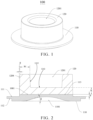
FIG. 1 is a schematic structural diagram of a pole post provided in an embodiment 1 of the disclosure. -
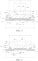
FIG. 2 is an axial sectional view of the pole post inFIG. 1 . -
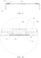
FIG. 3 is an axial sectional view of the pole post provided in an embodiment 2 of the disclosure. -
FIG. 4 is an axial sectional view of the pole post provided in an embodiment 3 of the disclosure. -
FIG. 5 is an axial sectional view of the pole post provided in an embodiment 4 of the disclosure. -
FIG. 6 is an axial sectional view of the pole post provided in an embodiment 5 of the disclosure. -
FIG. 7 is a schematic diagram of a top cap assembly provided in some embodiments of the disclosure. -
FIG. 8 is an exploded view of the top cap assembly inFIG. 7 . -
FIG. 9 is a sectional view of the top cap assembly inFIG. 7 . -
FIG. 10 is a locally enlarged view at position G inFIG. 9 . -
- 100, pole post; 1001, joint surface;
- 110, metal base; 1101, second groove; 111, flange; 112, first step; 113, boss;
- 1141, first concave portion; 11411, socket slot; 11412, buckle slot; 1142, second protrusion portion; 1143, third protrusion portion; 11431, second socket section; 11432, second buckle section;
- 115, annular groove; 116, second step;
- 120, metal post; 1201, first groove; 1202, bottom surface of the first groove; 1203, sidewall of the first groove; 1204, outer sidewall of the metal post;
- 1211, first protrusion portion; 12111, first socket section; 12112, first buckle section; 1212, second concave portion; 1213, third concave portion; 122, stretch line;
- 200, cap plate;
- 300, briquetting; 310, mounting hole; and
- 400, connecting sheet; 410, stepped hole.
- In the disclosure, the terms "connected" and "fixed" should be understood broadly, unless otherwise specified. For example, it can be a fixed connection, a detachable connection, or an integral connection; alternatively, it can be a mechanical connection or an electrical connection; and alternatively, it can be a direct connection, an indirect connection through an intermediate medium, an internal connection of two elements, or an interaction relationship between two elements. For ordinary skill in the art, specific meanings of the above terms in the disclosure may be understood based on specific application scenarios.
- In the disclosure, the expression that a first feature is disposed "on", "above", "under", or "below" a second feature indicates that the first feature is in direct contact with the second feature, or in indirect contact with the second feature through other features between them, unless otherwise specified. Moreover, the expression that the first feature is disposed "on" or "above" the second feature indicates that the first feature is directly above and diagonally above the second feature, or simply indicates that the first feature is horizontally higher than the second feature. The expression that the first feature is disposed "under" or "below" the second feature indicates that the first feature is directly below and diagonally below the second feature, or simply indicates that the horizontal height of the first feature is less than that of the second feature.
- In the disclosure, the terms "up", "down", "right", and other directional or positional relationships are based on the directional or positional relationships illustrated in the drawings, and are only for the convenience of description and simplification of operation, rather than indicating or implying that a device or a component must have a specific direction or should be constructed and operated in a specific direction. The terms cannot be understood as limitations to the disclosure. In addition, the terms "first", "second", or the like are only used to distinguish in the description of different features and have no special meanings.
- As illustrated in
FIGs. 1 to 6 , some embodiments of the disclosure provide apole post 100 used in a top cap assembly as a negative electrode of a battery. In some embodiments, as illustrated inFIGs. 7 to 10 , the top cap assembly includes acap plate 200, abriquetting 300, a connectingsheet 400, and thepole post 100. Amounting hole 310 is provided in thebriquetting 300. Thepole post 100 passes through thecap plate 200 and is matched with themounting hole 310. Thepole post 100 and thebriquetting 300 are fixed by laser welding. The briquetting 300 and the pole post 100 abut against two sides of thecap plate 200, respectively. An end of thepole post 100 is connected to an external circuit of the battery, and another end of thepole post 100 is connected to the connectingsheet 400 by welding. The connectingsheet 400 is connected to an electrode assembly in the battery, so as to achieve the function of charging and discharging. The structure of thecap plate 200 is clear to those of ordinary skill in the art and is not limited herein. - In some embodiments of the disclosure, the
pole post 100 includes ametal base 110 and ametal post 120. Themetal post 120 is disposed on a top of themetal base 110. Materials of themetal post 120 and themetal base 110 are different. A bottom of themetal post 120 is connected to a top of themetal base 110. A surface of themetal post 120 away from themetal base 110 is provided with afirst groove 1201. - In some embodiments, the
pole post 100 is formed by a copper-aluminum composite plate by a cold heading process. Compared to traditional pole posts formed by the friction welding process, the cold heading process improves the efficiency of producing thepole post 100, effectively reduces the waste of materials caused by the cutting process, and better controls the production cost. Moreover, the cold heading process enables the copper layer and the aluminum layer to be firmly bonded together, reducing the fracture risk of thepole post 100 and improving the reliability of thepole post 100. - In some embodiments, as illustrated in
FIGs. 2 to 6 , thepole post 100 includes themetal base 110 and themetal post 120 coaxially connected to each other, and peripheral dimensions of themetal base 110 and themetal post 120 decrease sequentially. Themetal base 110 is made of copper. Themetal post 120 is made of aluminum. An end surface of themetal base 110 is connected to an end surface of themetal post 120 to form ajoint surface 1001, which is a contact surface between themetal post 120 and themetal base 110. - In some embodiments, the
metal base 110 and themetal post 120 are both cylindrical structures, and an outer diameter of themetal base 110 is greater than an outer diameter of themetal post 120, so that themetal base 110 abuts against a lower surface of thecap plate 200 to achieve a limiting effect after themetal post 120 passes through thecap plate 200. - In some embodiments, as illustrated in
FIGs. 2 to 6 , thefirst groove 1201 is formed in themetal post 120 away from themetal base 110 by the cold heading process. The blanks undergo equal volume deformation by cold extrusion during the cold heading process, including forming thefirst groove 1201 on the top of themetal post 120 by the cold heading process, and enabling the material originally located at thefirst groove 1201 to move to other positions of themetal post 120. Because the diameter of themetal post 120 remains unchanged, the height of themetal post 120 increases during the cold heading process. While meeting the requirement for the dimensions, the process saves materials for producing themetal post 120, and reduces the cost of producing themetal post 120. Moreover, the setting of thefirst groove 1201 can reduce the weight of the top cap assembly of the battery to achieve a lightweight design. - In some embodiments, as illustrated in
FIG. 2 , abottom surface 1202 of thefirst groove 1201 is higher than a bottom surface of themetal post 120, that is, thebottom surface 1202 of thefirst groove 1201 is higher than thejoint surface 1001 between themetal post 120 and themetal base 110. In this setting, thefirst groove 1201 can be formed only in the metal post 120 (an aluminum layer) by cold heading without damaging the joint surface 1001 (a copper-aluminum joint surface) between themetal post 120 and themetal base 110, ensuring that the metal base 110 (the copper layer) and the metal post 120 (the aluminum layer) are firmly bonded together, reducing the fracture risk of thepole post 100, thereby improving the structural strength of thepole post 100. - As illustrated in
FIG. 2 , a distance K between thebottom surface 1202 of thefirst groove 1201 and the bottom surface of the metal post 120 (thejoint surface 1001 between themetal post 120 and the metal base 110) in an axial direction is greater than 0.5 mm and less than 2.5 mm. For example, the distance K between thebottom surface 1202 of thefirst groove 1201 and thejoint surface 1001 in the axial direction can be 0.6 mm, 0.8 mm, 1.0 mm, 1.2 mm, 1.4 mm, 1.6 mm, 1.8 mm, 2.0 mm, 2.2 mm, or 2.4 mm. By setting the distance K in the above range, the structural strength of thepole post 100 is improved, which prevents thepole post 100 from breaking at thejoint surface 1001 between themetal post 120 and themetal base 110. - In some embodiments, as illustrated in
FIG. 2 , a minimum distance W between asidewall 1203 of thefirst groove 1201 and anouter sidewall 1204 of themetal post 120 is greater than or equal to 1 mm. For example, the minimum distance W may be a minimum wall thickness of themetal post 120, and can be 1 mm, 2 mm, 3 mm, 4 mm, 5 mm, 6 mm, or 7 mm. By setting the minimum wall thickness of themetal post 120 in the above range, the structural strength of thepole post 100 is improved, which meets the requirement for welding strength, and improves the structural strength of the top cap assembly of the battery. - In some embodiments, as illustrated in
FIG. 2 , theouter sidewall 1204 of themetal post 120 is inclined relative to the axis of themetal post 120. An inclination direction and an inclination angle of an inner sidewall of the mountinghole 310 of thebriquetting 300 are respectively the same as an inclination direction and an inclination angle of theouter sidewall 1204 of themetal post 120, and theouter sidewall 1204 of themetal post 120 is matched with the inner sidewall of the mountinghole 310. In some embodiments, as illustrated inFIG. 2 , theouter sidewall 1204 of themetal post 120 is inclined towards the interior of themetal post 120 from bottom to top. In other embodiments, theouter sidewall 1204 of themetal post 120 can be inclined towards a direction close to thefirst groove 1201 from bottom to top, as long as the inner sidewall of the mountinghole 310 is set to have the same inclination direction and the same inclination angle as theouter sidewall 1204 of themetal post 120. That is, theouter sidewall 1204 of themetal post 120 and the inner sidewall of the mountinghole 310 are both inclined surfaces, so that themetal post 120 is matched with the mountinghole 310 through the inclined surface. On the one hand, the setting of the inclined surface prevents laser from irradiating and burning lower plastic component of thecap plate 200 during the laser welding process. On the other hand, thepole post 100 can be interlocked with thebriquetting 300 through the inclined surface at thejoint surface 1001, thereby improving the structural strength of thecap plate 200 of the battery. - In some embodiments, as illustrated in
FIG. 2 , an inclination angle θ between theouter sidewall 1204 of themetal post 120 and the axis of themetal post 120 is greater than 0° and less than or equal to 3°, for example, 1°, 2°, or 3°. By setting the inclination angle of theouter sidewall 1204 of themetal post 120 in the above range, preventing laser from irradiating and burning the lower plastic components during the laser welding process, enabling thepole post 100 to be interlocked with thebriquetting 300 at thejoint surface 1001, further improving the structural strength of thecap plate 200 of the battery. - As illustrated in
FIG. 1 and FIG. 2 , the peripheral dimensions of themetal base 110 and themetal post 120 decrease sequentially. A side of themetal base 110 close to themetal post 120 is provided with aboss 113. A peripheral dimension of theboss 113 is less than the peripheral dimension of themetal base 110 and substantially the same as a peripheral dimension of the bottom of themetal post 120. Theboss 113 is connected to themetal post 120, and a connecting end surface between theboss 113 and themetal post 120 is the joint surface 1001 (the copper-aluminum joint surface). When forming themetal base 110 by the cold heading process, aluminum used to form themetal post 120 and part copper used to form theboss 113 can be precisely limited by a sidewall of a concave cavity of a concave mold, and other copper outside the concave mold will be pressed by a protrusion mold to form themetal base 110. Therefore, the setting of theboss 113 limits the flow of aluminum, avoiding the dimension of themetal post 120 being too small caused by insufficient volume of aluminum. Moreover, it also makes themetal base 110 only form as the copper layer without damaging the copper-aluminum joint surface, thereby improving the structural strength of thepole post 100 and reducing the fracture risk of thepole post 100. - As illustrated in
FIG. 2 , theboss 113 has a height h greater than 0.3 mm and less than 1.2 mm. That is, a distance h between a top surface of theboss 113 and aflange 111 in an axial direction is greater than 0.3 mm and less than 1.2 mm. In some embodiments, the height h of theboss 113 can be 0.4 mm, 0.5 mm, 0.6 mm, 0.7 mm, 0.8 mm, 0.9 mm, 1.0 mm, or 1.1 mm. By setting the height h of theboss 113 in the above range, it can effectively avoid limiting the flow of aluminum during the cold heading process caused by the height h being too small, and avoid the increase of the amount of copper required for the higher height h. - In some embodiments, as illustrated in
FIG. 2 , a surface of themetal base 110 away from themetal post 120 is provided with asecond groove 1101. Apart of the bottom surface of themetal post 120 is located between thefirst groove 1201 and thesecond groove 1101. Apart of themetal base 110 extends outside a peripheral surface of themetal post 120 in a radial direction. By forming thesecond groove 1101 at the bottom of themetal base 110 by extrusion, the material originally located at thesecond groove 1101 of themetal base 110 extends radically outwards during the cold heading process. Because the volume is not changed after themetal base 110 deforms during the cold heading process, the diameter of themetal base 110 can be enlarged, and the dimension around thesecond groove 1101 can be enlarged accordingly to meet the requirement for the dimension. - In some embodiments, as illustrated in
FIG. 2 , a longitudinal sectional surface of thesecond groove 1101 is in an arc shape, and an angle β between a circumferential sidewall of thesecond groove 1101 and a horizontal plane is greater than or equal to 15° and less than or equal to 60°. For example, the angle β may be 15°, 20°, 25°, 30°, or 40°. By setting the angle β of the circumferential sidewall of thesecond groove 1101 in the above range, themetal base 110 has a larger diameter, providing better fluidity for copper used in the copper-aluminum composite plate, making the bottom of thepole post 100 less prone to fracture, thereby improving the structural strength of thepole post 100. In other embodiments, a shape of a circumferential sectional surface of thesecond groove 1101 may be, but not limited to, circular, square, elliptical, or other irregular shapes, and can be flexibly adapted according to the requirements without special limitations. - In some embodiments, the
flange 111 is formed at a peripheral surface of themetal base 110. Theflange 111 protrudes from an edge of themetal post 120 in a direction away from an axis of themetal base 110. That is, theflange 111 extends along the direction away from the axis of themetal base 110 and protrudes from the edge of themetal post 120. - In some embodiments, as illustrated in
FIG. 2 andFIG. 8 , a surface of theflange 111 away from themetal post 120 is provided with afirst step 112, a steppedhole 410 is provided in the connectingsheet 400, and thefirst step 112 is configured to be matched with the steppedhole 410. In some embodiments, the setting of thefirst step 112 makes themetal base 110 have two different outer diameters, and the steppedhole 410 includes two holes with different diameters. When themetal base 110 is matched with the connectingsheet 400, a part of themetal base 110 having a smaller outer diameter passes through one hole of the steppedhole 410 having a smaller diameter, a part of themetal base 110 having a larger outer diameter is matched with another hole of the steppedhole 410 having a larger diameter, and a stepped surface of thefirst step 112 of themetal base 110 abuts against a stepped surface of the steppedhole 410. This setting improves the positioning effect between themetal base 110 and the connectingsheet 400. After the installation, the mutual movement between themetal base 110 and the connectingsheet 400 is limited to facilitate the subsequent assembly and welding process. Moreover, the fitting of the two stepped surfaces can block the gap between a part of themetal base 110 having a smaller outer diameter and an inner sidewall of the steppedhole 410, avoiding the heat generated by welding from being transmitted to the lower plastic component of thecap plate 200 through the gap. - In some embodiments, the
joint surface 1001 between themetal base 110 and themetal post 120 is a flat surface. Thesecond groove 1101 is disposed corresponding to thefirst groove 1201. Thejoint surface 1001 between themetal base 110 and themetal post 120 undergoes a downward force when forming thefirst groove 1201, and undergoes an upward force when forming thesecond groove 1101. That is, thejoint surface 1001 between themetal base 110 and themetal post 120 undergoes two forces from opposite directions. The two forces cancel out, making thejoint surface 1001 between themetal base 110 and themetal post 120 be the flat surface. - The embodiment 2 of the disclosure is similar to the embodiment 1, and the part not described in detail can refer to the embodiment 1.
- As illustrated in
FIG. 3 , in the embodiment 2, a distance H between a top surface of themetal post 120 and a plane F where the bottom surface of themetal post 120 below thebottom surface 1202 of thefirst groove 1201 is located. The distance H, a volume V of thefirst groove 1201, and an area S of an orthogonal projection of themetal post 120 on themetal base 110 satisfy the following relationship: 3 mm ≤ H-V/S ≤10 mm. - The above relationship ensures that the dimension of the
pole post 100 can meet the requirement for the cold heading process, avoiding the waste of raw materials for producing thepole post 100, and reducing the production cost of thepole post 100. - In some embodiments, the
second groove 1101 is disposed at the bottom of themetal base 110. Themetal post 120 is disposed on the top of themetal base 110. The bottom of themetal post 120 is connected to at least a part of the top of themetal base 110. The distance H between the top surface of themetal post 120 and the plane F where the bottom surface of themetal post 120 between thefirst groove 1201 and thesecond groove 1101 is located. The distance H, the volume V of thefirst groove 1201, and the area S of the orthogonal projection of themetal post 120 on themetal base 110 satisfy the following relationship: 3 mm ≤ H-V/S ≤ 10 mm. - In some embodiments, when the
pole post 100 satisfies the above relationship, it can be prepared by the cold heading process. During the cold heading process, H0 represents a distance between an initial top surface of themetal post 120 and an initial bottom surface of themetal post 120 before the cold heading process, that is, an initial thickness of themetal post 120; and H represents the distance between the top surface of themetal post 120 and the plane F where the bottom surface of themetal post 120 between thefirst groove 1201 and thesecond groove 1101 is located after the cold heading process, that is, a molding thickness of themetal post 120. H0, H, V, and S satisfy the following equation: H0 = H-V/S. When the area S of the orthographic projection of themetal post 120 on themetal base 110 remains substantially unchanged, themetal post 120 originally positioned at thefirst groove 1201 extends to an unrestricted position due to the equal volume deformation of themetal post 120, which increases the height of themetal post 120. Therefore, the distance H between the top surface of themetal post 120 and the plane F where the bottom surface of themetal post 120 between thefirst groove 1201 and thesecond groove 1101 is located after cold heading is positively correlated with the volume V of thefirst groove 1201. - In the
pole post 100 of some embodiments, thefirst groove 1201 on themetal post 120 is formed by extrusion, increasing the distance H between the top surface of themetal post 120 and the plane F where the bottom surface of themetal post 120 between thefirst groove 1201 and thesecond groove 1101 is located, that is, increasing the thickness (height) of themetal post 120, so that the height of themetal post 120 meets the requirement for the height of thepole post 100 in the cell. - The
pole post 100 provided in some embodiments can be prepared by the cold heading process. Compared to the friction welding process in the related art, the cold heading process has less requirements for the process, has stronger operability, and needs lower processing temperature. Moreover, during the cold heading process, it is not easy to cause thermal stress of metal, avoiding the deformation caused by thermal stress on themetal base 110 and themetal post 120, avoiding cracks and even fractures on the welding surface of themetal base 110 and themetal post 120 caused by high temperature, thereby improving the reliability and safety of thepole post 100. - As illustrated in
FIG. 3 , in the embodiment 2 of the disclosure, thesecond groove 1101 is disposed in themetal base 110 away from themetal post 120, and disposed corresponding to thefirst groove 1201, so that themetal post 120 undergoes an extrusion force pointing from themetal base 110 to themetal post 120 during the cold heading process, which increases the bonding strength between themetal base 110 and themetal post 120 at thejoint surface 1001, strengthens the bonding strength between themetal base 110 and themetal post 120, and improves the reliability of thepole post 100. - In some embodiments, the
joint surface 1001 between themetal post 120 and themetal base 110 is recessed towards themetal base 110, which is formed when stamping thefirst groove 1201. In other embodiments, thejoint surface 1001 may be uneven. By setting thejoint surface 1001 being uneven, the contact surface between themetal post 120 and themetal base 110 is formed by fitting a concave surface with a convex surface, which improves the bonding strength between themetal post 120 and themetal base 110, ensures that the copper layer and the aluminum layer are firmly bonded, reduces the fracture risk of thepole post 100, and improves the structural strength of thepole post 100. - In some embodiments, a part of the bottom surface of the
metal post 120 is located between thefirst groove 1201 and thesecond groove 1101, a surface of themetal post 120 close to themetal base 110 is provided with afirst protrusion portion 1211 protruding towards themetal base 110. An orthographic projection of thefirst protrusion portion 1211 on a plane where themetal base 110 is located surrounds an orthographic projection of thebottom surface 1202 of thefirst groove 1201 on the plane where themetal base 110 is located. Thefirst protrusion portion 1211 extends towards themetal base 110. - A surface of the
metal base 110 close to themetal post 120 is provided with a firstconcave portion 1141 matched with thefirst protrusion portion 1211. A top surface of the firstconcave portion 1141 is in contact with a bottom surface of thefirst protrusion portion 1211. Thejoint surface 1001 between the firstconcave portion 1141 and thefirst protrusion portion 1211 is a curved surface. When themetal base 110 undergoes an external extrusion force at thesecond groove 1101, a part of themetal base 110 corresponding to thesecond groove 1101 moves towards themetal post 120, causing themetal post 120 located between thefirst groove 1201 and thesecond groove 1101 to extend towards the outer periphery of thesecond groove 1101, thereby forming thefirst protrusion portion 1211. - The top surface of the
metal base 110 is in direct contact with the bottom surface of themetal post 120. The top surface of themetal base 110 is provided with the firstconcave portion 1141 matched with thefirst protrusion portion 1211 of themetal post 120. That is, the firstconcave portion 1141 of themetal base 110 is in contact with thefirst protrusion portion 1211 of themetal post 120, which increases a contact area between themetal base 110 and themetal post 120, strengthens the bonding strength between themetal base 110 and themetal post 120, improves the reliability of thepole post 100, and effectively improves the fracture problem of thepole post 100. - In some embodiments, a part of the
joint surface 1001 between themetal base 110 and themetal post 120 is a curved surface, and an orthogonal projection of the curved surface on the plane where themetal base 110 is located surrounds an orthogonal projection of thesecond groove 1101 on the plane where themetal base 110 is located. Thefirst groove 1201 and thesecond groove 1101 are configured to be matched with an external cold heading equipment, so that the cold heading equipment can apply an extrusion force on themetal base 110 and themetal post 120, achieving the equal volume deformation of themetal base 110 and themetal post 120. At least a part of thejoint surface 1001 between themetal base 110 and themetal post 120 surrounding thesecond groove 1101 is a curved surface, that is, a part of thejoint surface 1001 between themetal base 110 and themetal post 120 is a curved surface, which increases the contact area between themetal base 110 and themetal post 120, forms an interlocking structure consisting of themetal base 110 and themetal post 120, strengthens the bonding strength between themetal base 110 and themetal post 120, and avoids the fracture risk of thepole post 100. - In some embodiments, the
metal base 110 and themetal post 120 have different hardness. - In some embodiments, the hardness of the
metal base 110 is greater than the hardness of themetal post 120. - In some embodiments, the number of the
first groove 1201 and thesecond groove 1101 are one, and the central axis of thefirst groove 1201 and the central axis of thesecond groove 1101 are in the same axis. - Both of the central axis of the
first groove 1201 and the central axis of thesecond groove 1101 coincide with the central axis of thepole post 100. - Alternatively, the number of the
second grooves 1101 is two or more than two. - As illustrated in
FIG. 3 , in some embodiments, a longitudinal sectional surface of a part of themetal post 120 and/or themetal base 110 overlapping with the curved surface has astretch line 122 that is a curve. A protruding direction of thestretch line 122 and a protruding direction of thefirst protrusion portion 1211 are the same. - In some embodiments, for the longitudinal sectional surface of the
pole post 100, both of a part of themetal post 120 overlapping with the curved surface and a part of themetal base 110 overlapping with the curved surface have thestretch line 122. The metal structural grains in themetal post 120 and themetal base 110 are arranged along thestretch line 122, and the atomic arrangement at the interfaces (grain boundary) among the metal structural grains is irregular, which improves the shaping resistance of themetal base 110 and themetal post 120, so that themetal base 110 and themetal post 120 have higher strength and hardness, and thepole post 100 has stronger impact resistance and compression resistance after being formed by the cold heading process. - In some embodiments, the method for observing the
stretch line 122 is as follows: cutting thepole post 100 along the axis of thepole post 100, immersing it in acidic liquid for a period of time, and observing the sectional surface of thepole post 100. Because the grain boundary has higher free energy, the grain boundary is susceptible to the corrosion of acidic solutions to form channels, showing thestretch line 122 formed by the arrangement of polygonal grains. - In some embodiments, the
pole post 100 is a copper-aluminum composite member. Themetal base 110 is the copper layer of a copper-aluminum composite member, and themetal post 120 is an aluminum layer of the copper-aluminum composite member. - In some embodiments, the copper-aluminum composite member is a composite member that combines a copper plate and an aluminum plate by special processes such as rolling and sintering processes before the cold heading process. That is, before the
pole post 100 is formed by the cold heading process, the aluminum layer is composite on the copper layer, and the copper-aluminum composite member is an integrated structure with the copper layer and the aluminum layer inseparable. For the cold heading process, the copper-aluminum composite member is placed in the cold heading equipment to perform the molding process of thepole post 100 by the cold heading process. Thejoint surface 1001 between themetal base 110 and themetal post 120 is the copper-aluminum joint surface after the cold heading process, and the copper-aluminum joint surface is thejoint surface 1001 formed by the original joint surface of the copper-aluminum composite member after undergoing the deformation during the cold heading process. - Alternatively, the
pole post 100 is a copper-aluminum embedding member. Themetal base 110 is a copper layer of the copper-aluminum embedding member, and themetal post 120 is an aluminum layer of the copper-aluminum embedding member. - In some embodiments, the copper-aluminum embedding member is an embedding structure in which the copper layer and the aluminum layer are separable before the cold heading process. The copper layer and the aluminum layer can be embedded with each other during the cold heading process or before the cold heading process. For example, the copper layer and the aluminum layer are embedded with each other by the butting of a clamping slot and a clamping tape, or by the meshing of convex teeth, or by riveting. Before the
pole post 100 is formed by the cold heading process, the copper layer and the aluminum layer are in contact with each other and do not form the composite, thejoint surface 1001 between themetal base 110 and themetal post 120 of the moldedpole post 100 is the copper-aluminum joint surface, which is formed after the cold heading of the copper-aluminum embedding member. After thepole post 100 is formed by the cold heading process, the copper layer is composite with the aluminum layer. - As illustrated in
FIG. 3 , in some embodiments, an angle α between thebottom surface 1202 of thefirst groove 1201 and thesidewall 1203 of thefirst groove 1201 is greater than 90° and less than 180°. A cross-sectional surface of thefirst groove 1201 is in an inverted trapezoidal shape, making a part of themetal post 120 below thefirst groove 1201 have a larger flow area, which strengthens the bonding strength between themetal post 120 and themetal base 110, improves the strength of themetal post 120 itself, and prevents impurities or dust from getting stuck in thefirst groove 1201. - In some embodiments, the angle α between the
bottom surface 1202 of thefirst groove 1201 and thesidewall 1203 of thefirst groove 1201, a diameter A1 of thebottom surface 1202 of thefirst groove 1201, a diameter A of a top opening of thefirst groove 1201, and a depth L of thefirst groove 1201 satisfy the following equation: A=A1+2 L tan(α-90°). When the diameter A1 of thebottom surface 1202 of thefirst groove 1201 and the depth L of thefirst groove 1201 are constant, the larger the angle α between thebottom surface 1202 of thefirst groove 1201 and thesidewall 1203 of thefirst groove 1201, the larger the diameter A of the top opening of thefirst groove 1201. - In some embodiments, the angle α between the
bottom surface 1202 of thefirst groove 1201 and thesidewall 1203 of thefirst groove 1201 is greater than 90 ° and less than 150 °. - In some embodiments, the angle α between the
bottom surface 1202 of thefirst groove 1201 and thesidewall 1203 of thefirst groove 1201 can be 92°, 93°, 94°, 95°, 98°, 100°, 103°, 105°, 106°, 107°, 108°, 109°, 110°, 112°, 113°, 115°, 116°, 117°, 120°, 125°, 130°, 134°, 135°, 140°, 142°, or 145°. - In the above range, because the difference between the diameter A1 of the
bottom surface 1202 of thefirst groove 1201 and the diameter A of the top opening of thefirst groove 1201 is small, there is no need to set a too deepfirst groove 1201 during the machining process of thepole post 100, which can significantly increase the height of themetal post 120 during the deformation process, avoid the depth of thefirst groove 1201 being too deep and exceeding the bottom surface of themetal post 120, improves the yield of thepole post 100, and solve the problem of the width of the top surface of themetal post 120 being too narrow caused by the top opening of thefirst groove 1201 being too large. - In some embodiments, a difference between a diameter of an inscribed circle of the orthographic projection of the
metal post 120 on themetal base 110 and a diameter of an inscribed circle of the orthographic projection of thefirst groove 1201 on themetal base 110 is greater than or equal to 2 mm, ensuring that the top surface of themetal post 120 has a width greater than or equal to 2 mm, and that the wall thickness of thefirst groove 1201 of themetal post 120 is large enough to improve the structural strength of thepole post 100. - In some embodiments, a shape of the orthogonal projection of the
first groove 1201 on themetal base 110 is circular, triangular, rectangular, or other polygon. - In some embodiments, the diameter of the inscribed circle of the orthographic projection of the
first groove 1201 on themetal base 110 is less than or equal to 40 mm. That is, a diameter of an inscribed circle of an opening of thefirst groove 1201 on themetal base 110 is less than or equal to 40 mm. Within this diameter range, the setting of thefirst groove 1201 increases the height of themetal post 120 of thepole post 100, and avoids the problem of excessive area occupied by themetal post 120 of thepole post 100 in the radial direction due to the opening of thefirst groove 1201. - In some embodiments, the
joint surface 1001 between themetal post 120 and themetal base 110 located between thesecond groove 1101 and thefirst groove 1201 is a flat surface. - As illustrated in
FIG. 3 , in some embodiments, themetal post 120 is a cylinder, and theouter sidewall 1204 of themetal post 120 is perpendicular to the top surface of themetal post 120, and perpendicular to the plane F where the bottom surface of themetal post 120 between thesecond groove 1101 and thefirst groove 1201 is located. The distance H0 between an initial top surface of themetal base 110 and an initial bottom surface of themetal post 120 before the cold heading process, and the distance H between the top surface of themetal base 110 and the plane F where the bottom surface of themetal post 120 between thesecond groove 1101 and thefirst groove 1201 is located after the cold heading process satisfy the following Equation 1:

- in which 3 mm ≤ H0 ≤10 mm, S0 represents an area of the orthographic projection of the bottom surface of the
metal post 120 on themetal base 110 before the cold heading process, S represents an area of the orthographic projection of the bottom surface of themetal post 120 on themetal base 110 after the cold heading process, and V represents a volume of thefirst groove 1201. - Because the area of the orthogonal projection of the bottom surface of the
metal post 120 on themetal base 110 has small changes during the cold heading process, it is considered that S0 is equal to S. Therefore, H, H0, and S satisfy the following equation: (H-H0)·S=V. - Alternatively, the
metal post 120 is a platform. An angle between theouter sidewall 1204 of themetal post 120 and the top surface of themetal post 120 is greater than or less than 90°, and an angle between theouter sidewall 1204 of themetal post 120 and the bottom surface of themetal post 120 between thesecond groove 1101 and thefirst groove 1201 is greater than or less than 90°. The distance H0 between the initial top surface of themetal post 120 and the initial bottom surface of themetal post 120 before the cold heading process, and the distance H between the top surface of themetal post 120 and the plane F where the bottom surface of themetal post 120 between thefirst groove 1201 and thesecond groove 1101 is located after the cold heading process satisfy the following equation:

in which 3 mm≤H0≤10 mm, S01 represents an area of the orthographic projection of the bottom surface of themetal post 120 on themetal base 110 after the cold heading process, S02 represents an area of the orthographic projection of the top surface of themetal post 120 on themetal base 110 after the cold heading process, S03 represents an area of the orthographic projection of the bottom surface of themetal post 120 on themetal base 110 before the cold heading process, S04 represents an area of the orthographic projection of the top surface of themetal post 120 on themetal base 110 before the cold heading process, and V represents the volume of thefirst groove 1201. Because the area of the orthographic projection of themetal post 120 on themetal base 110 has small changes during the cold heading process, and differences between S01 and S02, and between S03 and S04 are small, it is considered that S, S01, S02, S03, and S04 satisfy the following equation:

- In some embodiments, the
first groove 1201 is an inverted circular truncated cone, and the orthogonal projection of thefirst groove 1201 on themetal base 110 is circular. The volume V of thefirst groove 1201 satisfies the following Equation 2:

in which A1 represents a diameter of thebottom surface 1202 of thefirst groove 1201, A represents a diameter of the top opening of thefirst groove 1201, and L represents a depth of thefirst groove 1201. - The
metal post 120 is a cylinder, and the orthogonal projection of themetal post 120 on themetal base 110 is circular. The area S of the orthogonal projection of the bottom surface of themetal post 120 on themetal base 110 satisfies the following Equation 3:

in which D represents a diameter of the orthogonal projection of themetal post 120 on themetal base 110. - After substituting the Equation 3 into the Equation 1, the following equation is obtained:

- After substituting the Equation 2 into the equation "


- In some embodiments, when the distance H between the top surface of the
metal post 120 and the plane F where the bottom surface of themetal post 120 between thefirst groove 1201 and thesecond groove 1101 is located after the cold heading process satisfies the above equation, the equal volume deformation of themetal post 120 after the cold heading process can be achieved, and the waste of materials during processing can be avoided. - Alternatively, the
first groove 1201 is an inverted quadrangular frustum. The volume V of thefirst groove 1201 satisfies the following equation:

in which S1 represents an area of a top surface of the inverted quadrangular frustum, S2 represents an area of a bottom surface of the inverted quadrangular frustum, and L represents a distance between the top surface of the inverted pyramid and the bottom surface of the inverted quadrangular frustum. - In some embodiments, the orthogonal projection of the
first groove 1201 on themetal base 110 is in a square shape. The volume V of thefirst groove 1201 satisfies the following equation:

in which A2 represents a length of a side of the top surface of the inverted quadrangular frustum, A3 represents a length of a side of the bottom surface of the inverted quadrangular frustum, and L represents a distance between the top surface of the inverted pyramid and the bottom surface of the inverted quadrangular frustum. - Alternatively, the
first groove 1201 is an inverted triangular frustum. The volume V of thefirst groove 1201 satisfies the following equation:

in which S3 represents an area of a top surface of the inverted triangular frustum, S4 represents an area of a bottom surface of the inverted triangular frustum, and L represents a distance between the top surface of the inverted triangular frustum and the bottom surface of the inverted triangular frustum. - In some embodiments, the orthogonal projection of the
first groove 1201 on themetal base 110 is in an equilateral triangle shape. The volume V of thefirst groove 1201 satisfies the following equation:

in which a1 represents a length of a side of the top surface of the inverted triangular frustum, h1 represents a height of a side of the top surface of the inverted triangular frustum, a2 represents a length of a side of the bottom surface of the inverted triangular frustum, h2 represents a height of a side of the bottom surface of the inverted triangular frustum, and L represents a distance between the top surface of the inverted triangular frustum and the bottom surface of the inverted triangular frustum. - Alternatively, the
metal post 120 is a prism, and the orthogonal projection of themetal post 120 on themetal base 110 is in a square shape. The outer sidewall of themetal post 120 is perpendicular to the top surface of themetal post 120, and perpendicular to the plane F where the bottom surface of themetal post 120 between thefirst groove 1201 and thesecond groove 1101 is located. The area S of the orthogonal projection of the bottom surface of themetal post 120 on themetal base 110 satisfies the following equation:

in which D1 represents a length of a side of the orthographic projection of themetal post 120 on themetal base 110. - In some embodiments, after substituting the equation "S=D1 2" into the equation "(H-H0) S=V", the following equation is obtained: (H-H0) D1 2=V.
- Alternatively, the
metal post 120 is a prism, and the orthogonal projection of themetal post 120 on themetal base 110 is in a rectangle shape. The outer sidewall of themetal post 120 is perpendicular to the top surface of themetal post 120, and perpendicular to the plane F where the bottom surface of themetal post 120 between thefirst groove 1201 and thesecond groove 1101 is located. The area S of the orthogonal projection of the bottom surface of themetal post 120 on themetal base 110 satisfies the following equation:

in which D2 represents a length of the orthographic projection of themetal post 120 on themetal base 110, and W represents a width of the orthographic projection of themetal post 120 on themetal base 110. - In some embodiments, after substituting the equation "S=D2 W" into the equation "(H-H0) S=V", the following equation is obtained: (H-H0) D2 W=V.
- Alternatively, the
metal post 120 is a prism, and the orthogonal projection of themetal post 120 on themetal base 110 is in a triangle shape. The outer sidewall of themetal post 120 is perpendicular to the top surface of themetal post 120, and perpendicular to the plane F where the bottom surface of themetal post 120 between thefirst groove 1201 and thesecond groove 1101 is located. The area S of the orthogonal projection of the bottom surface of themetal post 120 on themetal base 110 satisfies the following equation:

in which D3 represents a length of a side of the orthographic projection of themetal post 120 on themetal base 110, and h3 represents a height of a side of the orthographic projection of themetal post 120 on themetal base 110. - In some embodiments, after substituting the equation "


- In some embodiments, when the
metal base 110 is extruded upwards to form thefirst groove 1201, an upward protrusion portion formed by themetal base 110 at the position corresponding to thefirst groove 1201 and a downward protrusion portion formed by themetal post 120 in a stretch deformation area cancel out. Therefore, the area S of the orthogonal projection of themetal post 120 on themetal base 110 is considered to be equal to the area of the bottom surface of themetal post 120. - In some embodiments, before the cold heading process, the distance H0 between the initial top surface of the
metal post 120 and the initial bottom surface of themetal post 120 ranges from 3 mm to 5 mm; and after the cold heading process, the distance H between the top surface of themetal post 120 and the plane F where the bottom surface of themetal post 120 between thesecond groove 1101 and thefirst groove 1201 is located ranges from 4.7 mm to 5.2 mm. - In some embodiments, the
outer sidewall 1204 of themetal post 120 is parallel to the axis of thepole post 100. - In some embodiments, the
outer sidewall 1204 of themetal post 120 is a first fixed surface of thepole post 100. During the cold heading process, the first fixed surface is fixed on the cold heading equipment, so that the area of the orthographic projection of themetal base 110 on themetal post 120 remains unchanged. During the process of forming thefirst groove 1201, themetal post 120 undergoes an external force and extends to themetal base 110, thereby achieving the increasing of the height of themetal base 110. By selecting the depth and/or the diameter of thefirst groove 1201, the volume of thefirst groove 1201 is controlled, so as to adjust the height of themetal post 120 without additional raw materials. - In some embodiments, the orthographic projection of the
metal post 120 on themetal base 110 is in a circular shape. The sidewall of themetal post 120 is perpendicular to the plane where themetal base 110 is located. Thefirst groove 1201 is in an inverted circular truncated cone shape. The angle α between thebottom surface 1202 of thefirst groove 1201 and thesidewall 1203 of thefirst groove 1201 is, for example, 135°. The diameter A of the top opening of thefirst groove 1201 is, for example, 14 mm. The diameter A1 of thebottom surface 1202 of thefirst groove 1201 is, for example, 10 mm. The depth L of thefirst groove 1201 is, for example, 2 mm. The diameter D of the orthogonal projection of themetal post 120 on themetal base 110 is, for example, 30 mm. Before the cold heading process, the distance H0 between the initial top surface of themetal post 120 and the initial bottom surface of themetal post 120 is, for example, 4 mm. After the cold heading process, the distance H between the top surface of themetal post 120 and the plane F where the bottom surface of themetal post 120 between thesecond groove 1101 and thefirst groove 1201 is located is, for example, 4.32 mm. - Alternatively, the orthogonal projection of the
metal post 120 on themetal base 110 is in a circular shape. The sidewall of themetal post 120 is perpendicular to the plane where themetal base 110 is located. Thefirst groove 1201 is in an inverted circular truncated cone shape. The angle α between thebottom surface 1202 of thefirst groove 1201 and thesidewall 1203 of thefirst groove 1201 is, for example, 120°. The diameter A of the top opening of thefirst groove 1201 is, for example, 9.1147 mm. The diameter A1 of thebottom surface 1202 of thefirst groove 1201 is, for example, 8 mm. The depth L of thefirst groove 1201 is, for example, 1 mm. The diameter D of the orthogonal projection of themetal post 120 on themetal base 110 is, for example, 12 mm. Before the cold heading process, the distance H0 between the initial top surface of themetal post 120 and the initial bottom surface of themetal post 120 is, for example, 4 mm. After the cold heading process, the distance H between the top surface of themetal post 120 and the plane F where the bottom surface of themetal post 120 between thesecond groove 1101 and thefirst groove 1201 is located is, for example, 4.51 mm. - In some embodiments, the diameter d of the inscribed circle of the orthogonal projection of the
metal base 110 on the plane where themetal base 110 is located and the diameter D of the inscribed circle of the orthogonal projection of themetal post 120 on the plane where themetal base 110 is located satisfy the following relationship: 0.5 ≤ D/d < 1. Under the condition of satisfying the above relationship, theflange 111 has a longer extension length, which improves the stability of the connection between thepole post 100 and thecap plate 200. - In some embodiments, the diameter d of the inscribed circle of the orthogonal projection of the
metal base 110 on the plane where themetal base 110 is located and the diameter D of the inscribed circle of the orthogonal projection of themetal post 120 on the plane where themetal base 110 is located satisfy the following relationship: 0.5 ≤ D/d < 1. That is, the ratio D/d of the minimum diameter D of themetal post 120 to the maximum diameter d of themetal base 110 is greater than or equal to 0.5 and less than 1. In some embodiments, when theouter sidewall 1204 of themetal post 120 is a vertical plane, the diameter of themetal post 120 in the axial direction remains unchanged and is the minimum diameter D of themetal post 120. When theouter sidewall 1204 of themetal post 120 is the inclined surface mentioned above, diameters of themetal post 120 at different points in the axis direction are different, the diameter of themetal post 120 at the thinnest position is the minimum diameter D of themetal post 120. As illustrated inFIG. 3 , themetal base 110 includes thefirst step 112, so the maximum diameter d of themetal base 110 is the diameter of the largest part of themetal base 110. For example, the ratio D/d can be 0.5, 0.6, 0.7, 0.8, or 0.9. By setting the ratio D/d in the above range, the disclosure improves the structural strength of thepole post 100, ensures that the outer diameter of themetal base 110 is greater than the outer diameter of themetal post 120, and allows themetal base 110 to abut against the lower surface of the top cap assembly to achieve a limiting effect after themetal post 120 passes through the top cap assembly. - In some embodiments, because the outer diameter of the
metal base 110 is greater than the outer diameter of themetal post 120, a part of themetal base 110 protrudes from theouter sidewall 1204 of themetal post 120 in a radial direction to form a protruding portion. In some embodiments, a thickness of the protruding portion decreases gradually in a radial direction away from themetal post 120, which saves copper materials and reduces the cost of the production. Moreover, it can reduce the weight of thepole post 100 and save space occupied by the raw materials due to the reduction of the copper materials. - In some embodiments, when the orthographic projection of the
metal base 110 on the plane where themetal base 110 is located is in a circular shape, the diameter d of the inscribed circle of the orthographic projection of themetal base 110 on the plane where themetal base 110 is located is equal to the diameter of the orthographic projection of themetal base 110 on the plane where themetal base 110 is located. - When the orthographic projection of the
metal base 110 on the plane where themetal base 110 is located is in a circular shape, the diameter D of the inscribed circle of the orthographic projection of themetal post 120 on the plane where themetal base 110 is located is equal to the diameter of the orthographic projection of themetal post 120 on the plane where themetal base 110 is located. - In some embodiments, the ratio D/d of the outer diameter d of the
metal base 110 to the outer diameter D of themetal post 120 can be 0.5, 0.6, 0.7, 0.8, or 0.9. - As illustrated in
FIG. 3 , in some embodiments, a surface of themetal base 110 close to themetal post 120 is provided with athird protrusion portion 1143. Thethird protrusion portion 1143 surrounds the outer periphery of a second protrusion portion of themetal post 120. A distance between a top surface of thethird protrusion portion 1143 and a top surface of theflange 111 is greater than 0.3 mm and less than 1.2 mm. - In some embodiments, the distance between the
bottom surface 1202 of thefirst groove 1201 and thejoint surface 1001 between themetal base 110 and themetal post 120 is greater than or equal to 0.5 mm, so that thebottom surface 1202 of thefirst groove 1201 is higher than thejoint surface 1001 between themetal base 110 and themetal post 120, avoiding thefirst groove 1201 exposing themetal base 110 caused by thefirst groove 1201 passing through themetal post 120. - In some embodiments, a cross-sectional surface of the
second groove 1101 is in a trapezoid shape. - In some embodiments, a rounded corner is formed between a sidewall of the
second groove 1101 and a bottom surface of thesecond groove 1101, and a rounded corner is formed between thesidewall 1203 of thefirst groove 1201 and a top surface of thefirst groove 1201. - By setting the connecting portions between the sidewall of the
second groove 1101 and the bottom surface of thesecond groove 1101, and between thesidewall 1203 of thefirst groove 1201 and the top surface of thefirst groove 1201 to be round, respectively, it is conducive to the flow deformation of themetal base 110 and themetal post 120. Moreover, it makes thepole post 100 undergo uniform force during the cold heading process, avoiding the fracture risk of themetal base 110 and/or themetal post 120 during the extrusion process. - As illustrated in
FIG. 4 , in this embodiment, thepole post 100 includes themetal base 110 and themetal post 120 connected to themetal base 110. A surface of themetal base 110 close to themetal post 120 is provided with the firstconcave portion 1141 matched with thefirst protrusion portion 1211. Asecond protrusion portion 1142 is provided at the center of themetal base 110. A secondconcave portion 1212 is provided at the center of themetal post 120. Thesecond protrusion portion 1142 is embedded into and connected to the secondconcave portion 1212. - The
metal base 110 is further provided with athird protrusion portion 1143 disposed surrounding thesecond protrusion portion 1142. The firstconcave portion 1141 is formed between thethird protrusion portion 1143 and thesecond protrusion portion 1142. Themetal post 120 is further provided with a thirdconcave portion 1213 disposed surrounding the secondconcave portion 1212. Thefirst protrusion portion 1211 is formed between the thirdconcave portion 1213 and the secondconcave portion 1212. Thethird protrusion portion 1143 is embedded into the thirdconcave portion 1213. Thefirst protrusion portion 1211 is embedded into the firstconcave portion 1141. - The
pole post 100 is prepared by a composite plate by the cold heading process, or, prepared by the cold heading of themetal base 110 and themetal post 120 disposed detachablely. Thepole post 100 is a negative pole post. Alternatively, one of themetal base 110 and themetal post 120 is a copper plate, and another of themetal base 110 and themetal post 120 is an aluminum plate. In some embodiments, themetal base 110 is a copper plate, and themetal post 120 is an aluminum plate. - The
pole post 100 provided in some embodiments is prepared by a copper-aluminum composite plate by the cold heading process. Compared to the traditional pole posts formed by friction welding, the cold heading process improves the efficiency of producing the pole posts, effectively reduces the waste of materials for producing the pole posts, and better controls the production cost of the pole post. By setting thesecond protrusion portion 1142 being embedded into the secondconcave portion 1212, thethird protrusion portion 1143 being embedded into the thirdconcave portion 1213, and thefirst protrusion portion 1211 being embedded into the firstconcave portion 1141, themetal base 110 can be connected to themetal post 120 to form the unevenjoint surface 1001, and the three sets of combinations of protrusion portions and concave portions increase the area of thejoint surface 1001, strengthen the bonding strength between themetal base 110 and themetal post 120, reduce the fracture risk of thepole post 100, and improve the reliability of thepole post 100. - In some embodiments, as illustrated in
FIG. 1 andFIG. 4 , both of themetal base 110 and themetal post 120 are cylindrical structures, and the outer diameter of themetal base 110 is greater than the outer diameter of themetal post 120, so that themetal base 110 abuts against the lower surface of the top cap assembly to achieve a limiting effect after themetal post 120 passes through the top cap assembly. Thesecond protrusion portion 1142, thethird protrusion portion 1143, and the firstconcave portion 1141 are all disposed surrounding themetal base 110 in a circumferential direction of themetal base 110. Thesecond protrusion portion 1142 and thethird protrusion portion 1143 are formed by the flow of the material for themetal base 110 during the cold heading process. The secondconcave portion 1212, the thirdconcave portion 1213, and thefirst protrusion portion 1211 are disposed surrounding themetal post 120 in a circumferential direction of themetal post 120. Thefirst protrusion portion 1211 is formed by the flow of the material for themetal post 120 during the cold heading process. - In some embodiments, during the cold heading process, a surface of the
metal base 110 away from themetal post 120 is provided with corrugated patterns in a radial direction. The corrugated patterns are naturally formed during the cold heading process, which increases the structural strength of themetal base 110. - As illustrated in
FIG. 4 , in some embodiments, thefirst protrusion portion 1211 includes afirst socket section 12111 and afirst buckle section 12112. An end of thefirst socket section 12111 is connected to themetal post 120, and another end of thefirst socket section 12111 is connected to thefirst buckle section 12112. An angle is formed between thefirst buckle section 12112 and thefirst socket section 12111. The firstconcave portion 1141 is matched with thefirst protrusion portion 1211. Thethird protrusion portion 1143 includes asecond socket section 11431 and a second buckle section 11432. An end of thesecond socket section 11431 is connected to themetal base 110, and another end of thesecond socket section 11431 is connected to the second buckle section 11432. An angle is formed between the second buckle section 11432 and thesecond socket section 11431. The thirdconcave portion 1213 is matched with thethird protrusion portion 1143. - The
first buckle section 12112 is embedded into a notch formed by the second buckle section 11432 and thesecond socket section 11431. The second buckle section 11432 is embedded into a notch formed by thefirst buckle section 12112 and thesocket section 12111. While increasing the area of thejoint surface 1001, thethird protrusion portion 1143 can be interlocked with thefirst protrusion portion 1211, strengthening the bonding strength between themetal base 110 and themetal post 120, reducing the fracture risk of thepole post 100, and improving the reliability of thepole post 100. - In some embodiments, the
first socket section 12111 and thefirst buckle section 12112 are connected to form a L-shaped structure, thesecond socket section 11431 and the second buckle section 11432 are connected to form a L-shaped structure, and thethird protrusion portion 1143 can be completely meshed and interlocked with thefirst protrusion portion 1211. The settings improve the interlocking effect between thethird protrusion portion 1143 and thefirst protrusion portion 1211. - In some embodiments, as illustrated in
FIG. 4 , a surface at the junction of thesecond protrusion portion 1142 and the secondconcave portion 1212 is a copper-aluminum joint surface, which is the originaljoint surface 1001 of the copper-aluminum composite plate. A part of thejoint surface 1001 at other positions is formed during the cold heading process. Thesecond protrusion portion 1142 is in complete contact with the secondconcave portion 1212 through the copper-aluminum joint surface to ensure the stability of the connection between themetal base 110 and themetal post 120. A gap is formed between a top of thethird protrusion portion 1143 and themetal post 120, enabling thethird protrusion portion 1143 and thefirst protrusion portion 1211 to meet the dimension requirement for interlocking, ensuring a better interlocking effect between thethird protrusion portion 1143 and thefirst protrusion portion 1211, further strengthening the bonding strength between themetal base 110 and themetal post 120, and reducing the fracture risk of thepole post 100. - In some embodiments, as illustrated in
FIG. 4 , thesecond groove 1101 is formed in themetal base 110 away from themetal post 120. In some embodiments, when using a cold heading mold to form themetal base 110 by the cold heading process, thesecond groove 1101 is formed by the cold heading process. At the same time, thesecond protrusion portion 1142 is formed at another side of themetal base 110 by the cold heading process, and the secondconcave portion 1212 matched with thesecond protrusion portion 1142 is formed at a side of themetal post 120 by the cold heading process. In addition, when forming thesecond groove 1101 at the bottom of themetal base 110 by the cold heading process, part of material of themetal base 110 extends radically outwards. Because the volume is not changed after themetal base 110 deforms during the cold heading process, the diameter of themetal base 110 can be enlarged, and the dimensions around thesecond groove 1101 can be enlarged accordingly to meet the requirement for the dimension. - In some embodiments, as illustrated in
FIG. 4 , anannular groove 115 is formed in themetal base 110 facing themetal post 120, and theannular groove 115 is disposed surrounding thethird protrusion portion 1143. By forming theannular groove 115 in themetal base 110 by the cold heading process, the material originally located at theannular groove 115 of themetal base 110 extends radically outwards during the cold heading process. Because the volume is not changed after themetal base 110 deforms during the cold heading process, the dimension of themetal base 110 and thethird protrusion portion 1143 can be enlarged, thereby improving the structural strength of themetal base 110 and saving material for producing themetal base 110. - As illustrated in
FIG. 4 , a peripheral dimension of thethird protrusion portion 1143 is greater than the peripheral dimension of themetal post 120, so as to form asecond step 116 between thethird protrusion portion 1143 and themetal post 120. Because aluminum has better fluidity than copper, the diameter of themetal post 120 is less than the diameter of thethird protrusion portion 1143 during the cold heading process to form thesecond step 116, which enhances the structural strength of thepole post 100. - In some embodiments, as illustrated in
FIG. 4 , thefirst groove 1201 is formed in themetal base 110 away from themetal post 120. By forming thefirst groove 1201 on the top of themetal post 120 by the cold heading process, the material originally located at thefirst groove 1201 can move to other positions of themetal post 120. While meeting the requirement for the dimension, because the diameter of themetal post 120 remains unchanged during the cold heading process, the height of themetal post 120 is increased, saving material for producing themetal post 120, and reducing the cost of producing themetal post 120. - The structure of the
pole post 100 provided in the embodiment 4 is similar to that of thepole post 100 provided in the embodiment 3. The same features will not be repeated here. The difference is in that thethird protrusion portion 1143 is not interlocked with thefirst protrusion portion 1211. - As illustrated in
FIG. 5 , in some embodiments, a surface of thefirst protrusion portion 1211 is an arc-shaped surface. The transition between the secondconcave portion 1212 and thefirst protrusion portion 1211 is smooth through the connecting of the arc-shaped surface. That is, a connecting surface between the secondconcave portion 1212 and thefirst protrusion portion 1211 is the arc-shaped surface. The transition between the thirdconcave portion 1213 and thefirst protrusion portion 1211 is also smooth, and a connecting surface between the thirdconcave portion 1213 and thefirst protrusion portion 1211 is an arc-shaped surface as well, so that thejoint surface 1001 between themetal base 110 and themetal post 120 is constructed in a wavy shape, thereby strengthening the bonding strength between themetal base 110 and themetal post 120 by increasing the area of thejoint surface 1001, reducing the fracture risk of thepole post 100, and improving the reliability of thepole post 100. - The structure of the
pole post 100 provided in the embodiment 5 is similar to that of thepole post 100 provided in the embodiment 3. The same features will not be repeated here. The difference is in the structures of thethird protrusion portion 1143 and thefirst protrusion portion 1211. - As illustrated in
FIG. 6 , in some embodiments, a shape of a longitudinal sectional surface of thethird protrusion portion 1143 is linear, and the longitudinal sectional surface of thethird protrusion portion 1143 is vertically connected to the upper surface of themetal base 110. The firstconcave portion 1141 includes asocket slot 11411 and abuckle slot 11412. An end of thesocket slot 11411 is provided with an opening for inserting thefirst protrusion portion 1211, which is in an open shape, and another end of thesocket slot 11411 is connected to thebuckle slot 11412. Thesocket slot 11411 is formed between thesecond protrusion portion 1142 and thethird protrusion portion 1143. An angle is formed between thebuckle slot 11412 and thesocket slot 11411. Thebuckle slot 11412 extends outward and into themetal post 120. Thesocket section 12111 is embedded into thesocket slot 11411, and thefirst socket section 12112 is embedded into thebuckle slot 11412, so that themetal base 110 and thefirst socket section 12112 can form an interlocking mechanism, strengthening the bonding strength between themetal base 110 and themetal post 120, reducing the fracture risk of thepole post 100, and improving the reliability of thepole post 100. - In some embodiments, the
socket section 12111 and thefirst buckle section 12112 are connected to form a L-shaped structure, and thesocket slot 11411 and thebuckle slot 11412 are connected to form a L-shaped slot, thereby improving the interlocking effect of themetal base 110 and thefirst buckle section 12112, further strengthening the bonding strength between themetal base 110 and themetal post 120, reducing the fracture risk of thepole post 100, and improving the reliability of thepole post 100. - As illustrated in
FIGs. 7 to 10 , embodiments of the disclosure further provide a top cap assembly, which includes thecap plate 200 and thepole post 100 as discussed above. Thepole post 100 is disposed on thecap plate 200. - In some embodiments, the top cap assembly further includes the
briquetting 300, the connectingsheet 400, and thepole post 100. The mountinghole 310 is provided in thebriquetting 300. Thepole post 100 passes through thecap plate 200 and is matched with the mountinghole 310. Thepole post 100 and thebriquetting 300 are fixed by laser welding. Thebriquetting 300 and thepole post 100 abut against two sides of thecap plate 200, respectively. - Embodiments of the disclosure further provide a cell, which includes a housing, an electrode assembly, and a top cap assembly. The top cap assembly includes the
pole post 100 as discussed above. The electrode assembly is disposed in an internal cavity of the housing. Thecap plate 200 of the top cap assembly is connected to the housing. The electrode assembly is electrically connected to thepole post 100 of the top cap assembly. By using thepole post 100, the cost of the cell can be reduced and the safety of the cell can be improved. - Embodiments of the disclosure further provide a battery module, which includes the cell as discussed above. By using the cell, the cost of the battery module can be reduced and the safety of the battery module can be improved.
- Embodiments of the disclosure further provide a battery pack, which includes the battery module as discussed above. By using the battery module, the cost of the battery pack can be reduced and the safety of the battery pack can be improved.
Claims (18)
- A pole post (100), characterized in that the pole post (100) comprises:a metal base (110);a metal post (120) disposed on a top of the metal base (110), wherein a material of the metal post (120) is different from a material of the metal base (110), a bottom of the metal post (120) is connected to a top of the metal base (110), and a surface of the metal post (120) away from the metal base (110) is provided with a first groove (1201).
- The pole post (100) of claim 1, characterized in that a distance H between a top surface of the metal post (120) and a plane where the bottom surface of the metal post (120) below the bottom surface (1202) of the first groove (1201) is located, a volume V of the first groove (1201), and an area S of an orthogonal projection of the metal post (120) on the metal base (110) satisfy the following relationship: 3 mm ≤ H-V/S ≤10 mm; or
a surface of the metal base (110) away from the metal post (120) is provided with a second groove (1101), a part of the bottom surface of the metal post (120) is located between the first groove (1201) and the second groove (1101), and a part of the metal base (110) protrudes from a peripheral surface of the metal post (120) in a radial direction; and a longitudinal sectional surface of the second groove (1101) is in an arc shape, and an angle β between a circumferential sidewall of the second groove (1101) and a horizontal plane is greater than or equal to 15° and less than or equal to 60°. - The pole post (100) of claim 1, characterized in that a peripheral surface of the metal base (110) is provided with a flange (111), and the flange (111) protrudes from an edge of the metal post (120) in a direction away from an axis of the metal base (110).
- The pole post (100) of claim 3, characterized in that a surface of the flange (111) away from the metal post (120) is provided with a first step (112); and the first step (112) is disposed surrounding an outer edge of the metal base (110) and configured to be matched with a stepped hole (410) of a connecting sheet (400) of a top cap assembly.
- The pole post (100) of claim 1, characterized in that a joint surface (1001) between the metal post (120) and the metal base (110) is recessed towards the metal base (110), or a joint surface (1001) between the metal post (120) and the metal base (110) is uneven.
- The pole post (100) of claim 5, characterized in that a surface of the metal base (110) away from the metal post (120) is provided with a second groove (1101), and a part of the bottom surface of the metal post (120) is located between the first groove (1201) and the second groove (1101); and a surface of the metal post (120) close to the metal base (110) is provided with a first protrusion portion (1211) protruding towards the metal base (110), and an orthographic projection of the first protrusion portion (1211) on a plane where the metal base (110) is located surrounds outside an orthographic projection of a bottom surface (1202) of the first groove (1201) on the plane where the metal base (110) is located.
- The pole post (100) of claim 6, characterized in that a surface of the metal base (110) close to the metal post (120) is provided with a first concave portion (1141) matched with the first protrusion portion (1211), a top surface of the first concave portion (1141) is in contact with a bottom surface of the first protrusion portion (1211), and a joint surface (1001) between the first concave portion (1141) and the first protrusion portion (1211) is a curved surface.
- The pole post (100) of claim 7, characterized in that a longitudinal sectional surface of a part of the metal post (120) overlapping with the curved surface comprises a stretch line (122), which is a curve; and a protruding direction of the stretch line (122) and a protruding direction of the first protrusion portion (1211) are same.
- The pole post (100) of claim 6, characterized in that a surface of the metal base (110) close to the metal post (120) is provided with a first concave portion (1141) matched with the first protrusion portion (1211); and the metal base (110) is provided with a second protrusion portion (1142), the metal post (120) is provided with a second concave portion (1212), and the second protrusion portion (1142) is embedded into and connected to the second concave portion (1212); and
wherein the metal base (110) is further provided with a third protrusion portion (1143) disposed surrounding the second protrusion portion (1142), and the first concave portion (1141) is formed between the third protrusion portion (1143) and the second protrusion portion (1142); the metal post (120) is further provided with a third concave portion (1213) disposed surrounding the second concave portion (1212), and the first protrusion portion (1211) is formed between the third concave portion (1213) and the second concave portion (1212); and the third protrusion portion (1143) is embedded into the third concave portion (1213), and the first protrusion portion (1211) is embedded into the first concave portion (1141). - The pole post (100) of claim 9, characterized in that the first protrusion portion (1211) comprises a first socket section (12111) and a first buckle section (12112), an end of the first socket section (12111) is connected to the metal post (120), and another end of the first socket section (12111) is connected to the first buckle section (12112); an angle is formed between the first buckle section (12112) and the first socket section (12111); and the first concave portion (1141) is matched with the first protrusion portion (1211).
- The pole post (100) of claim 10, characterized in that the third protrusion portion (1143) comprises a second socket section (11431) and a second buckle section (11432), an end of the second socket section (11431) is connected to the metal base (110), and another end of the second socket section (11431) is connected to the second buckle section (11432); an angle is formed between the second buckle section (11432) and the second socket section (11431); and the third concave portion (1213) is matched with the third protrusion portion (1143); or
the first concave portion (1141) comprises a socket slot (11411) and a buckle slot (11412), an end of the socket slot (11411) is provided with an opening for inserting the first protrusion portion (1211), and another end of the socket slot (11411) is connected to the buckle slot (11412); an angle is formed between the buckle slot (11412) and the socket slot (11411), and the buckle slot (11412) extends into the metal post (120); and the first socket section (12111) is embedded into the socket slot (11411), the first buckle section (12112) is embedded into the buckle slot (11412), and the metal base (110) and the first buckle section (12112) form an interlocking mechanism. - The pole post (100) of claim 11, characterized in that the first buckle section (12112) is embedded into a notch formed by the second buckle section (11432) and the second socket section (11431), and the second buckle section (11432) is embedded into a notch formed by the first buckle section (12112) and the first socket section (12111), enabling the third protrusion portion (1143) to be interlocked with the first protrusion portion (1211); and
the first socket section (12111) and the first buckle section (12112) are connected to form a L-shaped structure, the second socket section (11431) and the second buckle section (11432) are connected to form a L-shaped structure, and the third protrusion portion (1143) is engaged and interlocked with the first protrusion portion (1211). - The pole post (100) of any one of claims 9 to 12, characterized in that a surface at junction of the second protrusion portion (1142) and the second concave portion (1212) is a joint surface (1001), and a gap is formed between a top of the third protrusion portion (1143) and the metal post (120); ora peripheral dimension of the third protrusion portion (1143) is greater than a peripheral dimension of the metal post (120), and a second step is formed between the third protrusion portion (1143) and the metal post (120); oran annular groove (115) is formed in the metal base (110) facing the metal post (120), and the annular groove (115) is disposed surrounding the third protrusion portion (1143).
- The pole post (100) of any one of claims 5 to 12, characterized in that a peripheral dimension of the metal base (110) is greater than a peripheral dimension of the metal post (120); and a side of the metal base (110) close to the metal post (120) is provided with a boss (113) connected to the metal post (120), and a peripheral dimension of the boss (113) is less than a peripheral dimension of the metal base (110).
- The pole post (100) of any one of claims 1 to 12, characterized in that the pole post (120) is a copper-aluminum composite member, the metal base (110) is a copper layer of the copper-aluminum composite member, and the metal post (120) is an aluminum layer of the copper-aluminum composite member; or
the pole post (120) is a copper-aluminum embedding member, the metal base (110) is a copper layer of the copper-aluminum embedding member, and the metal post (120) is an aluminum layer of the copper-aluminum embedding member. - The pole post (100) of any one of claims 1 to 12, characterized in that a peripheral dimension of the metal base (110) is greater than a peripheral dimension of the metal post (120), and a thickness of a part of the metal base (110) protruding from the metal post (120) in a radial direction decreases gradually in a radial direction away from the metal post (120); orthe pole post (100) is formed by a cold heading process; orthe pole post (100) is a negative pole post; oran angle between a bottom surface (1202) of the first groove (1201) and a sidewall (1203) of the first groove (1201) is greater than 90° and less than 180°; oran outer sidewall (1204) of the metal post (120) is inclined relative to an axis of the metal post (120), and an angle between the outer sidewall (1204) of the metal post (120) and the axis of the metal post (120) is greater than 0° and less than or equal to 3°; ora difference between a diameter of an inscribed circle of an orthographic projection of the metal post (120) on the metal base (110) and a diameter of an inscribed circle of an orthographic projection of the first groove (1201) on the metal base (110) is greater than or equal to 2 mm; ora minimum distance W between a sidewall (1203) of the first groove (1201) and an outer sidewall (1204) of the metal post (120) is greater than or equal to 1 mm; ora diameter of an inscribed circle of an orthographic projection of the first groove (1201) on the metal base (110) is less than or equal to 40 mm; ora diameter d of an inscribed circle of an orthogonal projection of the metal base (110) on a plane where the metal base (110) is located and a diameter D of an inscribed circle of an orthogonal projection of the metal post (120) on the plane where the metal base (110) is located satisfy the following relationship: 0.5 ≤ Did < 1.
- A top cap assembly, characterized in that the top cap assembly comprises:a cap plate (200); andthe pole post (100) as claimed in any one of claims 1 to 16, wherein the pole post (100) is disposed on the cap plate (200).
- A cell, characterized in that the cell comprises a housing, an electrode assembly, and a top cap assembly; wherein the top cap assembly comprises a cap plate (200) and the pole post (100) as claimed in any one of claims 1 to 16, and the pole post (100) is disposed on the cap plate (200); and the electrode assembly is disposed in an internal cavity of the housing, the cap plate (200) is connected to the housing, and the electrode assembly is electrically connected to the pole post (100).
Applications Claiming Priority (5)
| Application Number | Priority Date | Filing Date | Title |
|---|---|---|---|
| CN202321467865 | 2023-06-09 | ||
| CN202321913353.1U CN220291029U (en) | 2023-07-20 | 2023-07-20 | A pole, battery cell, battery module and battery pack |
| CN202323075725.0U CN221841980U (en) | 2023-06-09 | 2023-11-14 | Pole, top cover assembly and battery cell |
| CN202311516756.7A CN119297543A (en) | 2023-06-09 | 2023-11-14 | Pole, top cover assembly and battery cell |
| PCT/CN2024/088831 WO2024250852A1 (en) | 2023-06-09 | 2024-04-19 | Pole, top cover assembly, battery cell, battery module, and battery pack |
Publications (1)
| Publication Number | Publication Date |
|---|---|
| EP4478496A1 true EP4478496A1 (en) | 2024-12-18 |
Family
ID=93794981
Family Applications (1)
| Application Number | Title | Priority Date | Filing Date |
|---|---|---|---|
| EP24181147.0A Pending EP4478496A1 (en) | 2023-06-09 | 2024-06-10 | Pole post, top cap assembly, and cell |
Country Status (4)
| Country | Link |
|---|---|
| US (1) | US20240413441A1 (en) |
| EP (1) | EP4478496A1 (en) |
| MX (1) | MX2025009721A (en) |
| WO (1) | WO2024250852A1 (en) |
Families Citing this family (2)
| Publication number | Priority date | Publication date | Assignee | Title |
|---|---|---|---|---|
| WO2026153113A1 (en) * | 2025-01-14 | 2026-07-23 | 惠州亿纬锂能股份有限公司 | Composite metal assembly, pole, cover plate assembly, and battery cell |
| CN120109392A (en) * | 2025-03-07 | 2025-06-06 | 阳光电源股份有限公司 | A cover plate assembly, battery cell and battery pack |
Citations (4)
| Publication number | Priority date | Publication date | Assignee | Title |
|---|---|---|---|---|
| JP2017103127A (en) * | 2015-12-03 | 2017-06-08 | 福井鋲螺株式会社 | Terminal, storage battery, and method for manufacturing terminal |
| CN211428205U (en) * | 2019-12-04 | 2020-09-04 | 武汉富航精密工业有限公司 | Novel simple structure of lithium battery cover plate |
| WO2023036291A1 (en) * | 2021-09-09 | 2023-03-16 | 江苏正力新能电池技术有限公司 | Composite pole, top cover, and battery |
| WO2024055666A1 (en) * | 2023-05-09 | 2024-03-21 | 湖北亿纬动力有限公司 | Post terminal, top cover structure, battery, battery module and battery pack |
Family Cites Families (8)
| Publication number | Priority date | Publication date | Assignee | Title |
|---|---|---|---|---|
| CN210956834U (en) * | 2019-11-26 | 2020-07-07 | 武汉富航精密工业有限公司 | Novel compound utmost point post of lithium cell top cap piece |
| CN212011128U (en) * | 2019-12-04 | 2020-11-24 | 武汉富航精密工业有限公司 | Novel compound utmost point post of lithium cell apron |
| CN214043929U (en) * | 2020-09-10 | 2021-08-24 | 武汉富航精密工业有限公司 | Structure of power battery copper-aluminum composite pole |
| CN213989132U (en) * | 2020-12-11 | 2021-08-17 | 厦门海辰新能源科技有限公司 | Light-duty utmost point post subassembly, top cap structure and power battery |
| CN216958439U (en) * | 2022-01-26 | 2022-07-12 | 江苏正力新能电池技术有限公司 | Composite pole, top cover and battery |
| CN218783181U (en) * | 2022-11-11 | 2023-03-31 | 湖北亿纬动力有限公司 | Top cap subassembly and battery |
| CN220291029U (en) * | 2023-07-20 | 2024-01-02 | 湖北亿纬动力有限公司 | A pole, battery cell, battery module and battery pack |
| CN220710580U (en) * | 2023-07-20 | 2024-04-02 | 湖北亿纬动力有限公司 | A pole, top cover structure, battery core, battery module and battery pack |
-
2024
- 2024-04-19 WO PCT/CN2024/088831 patent/WO2024250852A1/en not_active Ceased
- 2024-06-09 US US18/738,017 patent/US20240413441A1/en active Pending
- 2024-06-10 EP EP24181147.0A patent/EP4478496A1/en active Pending
-
2025
- 2025-08-18 MX MX2025009721A patent/MX2025009721A/en unknown
Patent Citations (4)
| Publication number | Priority date | Publication date | Assignee | Title |
|---|---|---|---|---|
| JP2017103127A (en) * | 2015-12-03 | 2017-06-08 | 福井鋲螺株式会社 | Terminal, storage battery, and method for manufacturing terminal |
| CN211428205U (en) * | 2019-12-04 | 2020-09-04 | 武汉富航精密工业有限公司 | Novel simple structure of lithium battery cover plate |
| WO2023036291A1 (en) * | 2021-09-09 | 2023-03-16 | 江苏正力新能电池技术有限公司 | Composite pole, top cover, and battery |
| WO2024055666A1 (en) * | 2023-05-09 | 2024-03-21 | 湖北亿纬动力有限公司 | Post terminal, top cover structure, battery, battery module and battery pack |
Also Published As
| Publication number | Publication date |
|---|---|
| WO2024250852A1 (en) | 2024-12-12 |
| MX2025009721A (en) | 2025-09-02 |
| US20240413441A1 (en) | 2024-12-12 |
Similar Documents
| Publication | Publication Date | Title |
|---|---|---|
| US20240413441A1 (en) | Pole post, top cap assembly, and cell | |
| CA2908760C (en) | Battery case | |
| WO2022152042A1 (en) | Explosion-proof valve for battery cell, battery cell, and battery module | |
| EP2425475B1 (en) | Battery with battery safety vent | |
| KR101616621B1 (en) | Battery case and method for forming a safety valve of the battery case | |
| CN220291029U (en) | A pole, battery cell, battery module and battery pack | |
| CN1349666A (en) | Square cell container and method of mfg. the cell container | |
| JP7538934B1 (en) | Explosion-proof valve for cell top cover and cell top cover | |
| EP4080658B1 (en) | Safety apparatus and battery | |
| US20250158252A1 (en) | Terminal, top cover structure, battery cell, battery module, and battery pack | |
| CN115377574B (en) | Integral forming process of top cover plate and explosion-proof valve | |
| CN116748435A (en) | Cold heading forming process of negative pole, negative pole, battery top cover and battery | |
| CN118173948A (en) | Cylindrical battery, electronic device and method for manufacturing cylindrical battery | |
| EP4611135A1 (en) | Battery top cover, power battery, and assembly process for battery top cover | |
| CN219350555U (en) | Power battery shell | |
| JP5093131B2 (en) | Manufacturing method of rivet terminal | |
| KR102694300B1 (en) | The cylindrical can of secondary battery and its manufacturing method | |
| CN216980702U (en) | Explosion-proof housing and battery with explosion-proof housing | |
| CN221841980U (en) | Pole, top cover assembly and battery cell | |
| KR20250071589A (en) | The cylindrical can of secondary battery | |
| CN116190906A (en) | Power battery casing and manufacturing method thereof | |
| CN223871645U (en) | Battery explosion-proof housing and battery cells | |
| CN217889425U (en) | Riveting assembly and riveting device | |
| CN223978048U (en) | Connecting sheet | |
| CN222867955U (en) | Explosion-proof plate, cap assembly and cylindrical lithium battery |
Legal Events
| Date | Code | Title | Description |
|---|---|---|---|
| PUAI | Public reference made under article 153(3) epc to a published international application that has entered the european phase |
Free format text: ORIGINAL CODE: 0009012 |
|
| STAA | Information on the status of an ep patent application or granted ep patent |
Free format text: STATUS: REQUEST FOR EXAMINATION WAS MADE |
|
| 17P | Request for examination filed |
Effective date: 20240610 |
|
| AK | Designated contracting states |
Kind code of ref document: A1 Designated state(s): AL AT BE BG CH CY CZ DE DK EE ES FI FR GB GR HR HU IE IS IT LI LT LU LV MC ME MK MT NL NO PL PT RO RS SE SI SK SM TR |