EP4478489A1 - Battery module and energy storage device - Google Patents
Battery module and energy storage device Download PDFInfo
- Publication number
- EP4478489A1 EP4478489A1 EP24173570.3A EP24173570A EP4478489A1 EP 4478489 A1 EP4478489 A1 EP 4478489A1 EP 24173570 A EP24173570 A EP 24173570A EP 4478489 A1 EP4478489 A1 EP 4478489A1
- Authority
- EP
- European Patent Office
- Prior art keywords
- cooling tube
- liquid cooling
- liquid
- collecting pipe
- bus
- Prior art date
- Legal status (The legal status is an assumption and is not a legal conclusion. Google has not performed a legal analysis and makes no representation as to the accuracy of the status listed.)
- Pending
Links
Images





Classifications
-
- H—ELECTRICITY
- H01—ELECTRIC ELEMENTS
- H01M—PROCESSES OR MEANS, e.g. BATTERIES, FOR THE DIRECT CONVERSION OF CHEMICAL ENERGY INTO ELECTRICAL ENERGY
- H01M10/00—Secondary cells; Manufacture thereof
- H01M10/60—Heating or cooling; Temperature control
- H01M10/61—Types of temperature control
- H01M10/613—Cooling or keeping cold
-
- H—ELECTRICITY
- H01—ELECTRIC ELEMENTS
- H01M—PROCESSES OR MEANS, e.g. BATTERIES, FOR THE DIRECT CONVERSION OF CHEMICAL ENERGY INTO ELECTRICAL ENERGY
- H01M10/00—Secondary cells; Manufacture thereof
- H01M10/60—Heating or cooling; Temperature control
- H01M10/62—Heating or cooling; Temperature control specially adapted for specific applications
- H01M10/625—Vehicles
-
- H—ELECTRICITY
- H01—ELECTRIC ELEMENTS
- H01M—PROCESSES OR MEANS, e.g. BATTERIES, FOR THE DIRECT CONVERSION OF CHEMICAL ENERGY INTO ELECTRICAL ENERGY
- H01M10/00—Secondary cells; Manufacture thereof
- H01M10/60—Heating or cooling; Temperature control
- H01M10/65—Means for temperature control structurally associated with the cells
- H01M10/655—Solid structures for heat exchange or heat conduction
- H01M10/6553—Terminals or leads
-
- H—ELECTRICITY
- H01—ELECTRIC ELEMENTS
- H01M—PROCESSES OR MEANS, e.g. BATTERIES, FOR THE DIRECT CONVERSION OF CHEMICAL ENERGY INTO ELECTRICAL ENERGY
- H01M10/00—Secondary cells; Manufacture thereof
- H01M10/60—Heating or cooling; Temperature control
- H01M10/65—Means for temperature control structurally associated with the cells
- H01M10/655—Solid structures for heat exchange or heat conduction
- H01M10/6556—Solid parts with flow channel passages or pipes for heat exchange
-
- H—ELECTRICITY
- H01—ELECTRIC ELEMENTS
- H01M—PROCESSES OR MEANS, e.g. BATTERIES, FOR THE DIRECT CONVERSION OF CHEMICAL ENERGY INTO ELECTRICAL ENERGY
- H01M10/00—Secondary cells; Manufacture thereof
- H01M10/60—Heating or cooling; Temperature control
- H01M10/65—Means for temperature control structurally associated with the cells
- H01M10/656—Means for temperature control structurally associated with the cells characterised by the type of heat-exchange fluid
- H01M10/6567—Liquids
-
- H—ELECTRICITY
- H01—ELECTRIC ELEMENTS
- H01M—PROCESSES OR MEANS, e.g. BATTERIES, FOR THE DIRECT CONVERSION OF CHEMICAL ENERGY INTO ELECTRICAL ENERGY
- H01M10/00—Secondary cells; Manufacture thereof
- H01M10/60—Heating or cooling; Temperature control
- H01M10/65—Means for temperature control structurally associated with the cells
- H01M10/656—Means for temperature control structurally associated with the cells characterised by the type of heat-exchange fluid
- H01M10/6567—Liquids
- H01M10/6568—Liquids characterised by flow circuits, e.g. loops, located externally to the cells or cell casings
-
- H—ELECTRICITY
- H01—ELECTRIC ELEMENTS
- H01M—PROCESSES OR MEANS, e.g. BATTERIES, FOR THE DIRECT CONVERSION OF CHEMICAL ENERGY INTO ELECTRICAL ENERGY
- H01M50/00—Constructional details or processes of manufacture of the non-active parts of electrochemical cells other than fuel cells, e.g. hybrid cells
- H01M50/20—Mountings; Secondary casings or frames; Racks, modules or packs; Suspension devices; Shock absorbers; Transport or carrying devices; Holders
- H01M50/204—Racks, modules or packs for multiple batteries or multiple cells
-
- H—ELECTRICITY
- H01—ELECTRIC ELEMENTS
- H01M—PROCESSES OR MEANS, e.g. BATTERIES, FOR THE DIRECT CONVERSION OF CHEMICAL ENERGY INTO ELECTRICAL ENERGY
- H01M50/00—Constructional details or processes of manufacture of the non-active parts of electrochemical cells other than fuel cells, e.g. hybrid cells
- H01M50/20—Mountings; Secondary casings or frames; Racks, modules or packs; Suspension devices; Shock absorbers; Transport or carrying devices; Holders
- H01M50/204—Racks, modules or packs for multiple batteries or multiple cells
- H01M50/207—Racks, modules or packs for multiple batteries or multiple cells characterised by their shape
- H01M50/209—Racks, modules or packs for multiple batteries or multiple cells characterised by their shape adapted for prismatic or rectangular cells
-
- H—ELECTRICITY
- H01—ELECTRIC ELEMENTS
- H01M—PROCESSES OR MEANS, e.g. BATTERIES, FOR THE DIRECT CONVERSION OF CHEMICAL ENERGY INTO ELECTRICAL ENERGY
- H01M50/00—Constructional details or processes of manufacture of the non-active parts of electrochemical cells other than fuel cells, e.g. hybrid cells
- H01M50/50—Current conducting connections for cells or batteries
- H01M50/502—Interconnectors for connecting terminals of adjacent batteries; Interconnectors for connecting cells outside a battery casing
-
- H—ELECTRICITY
- H01—ELECTRIC ELEMENTS
- H01M—PROCESSES OR MEANS, e.g. BATTERIES, FOR THE DIRECT CONVERSION OF CHEMICAL ENERGY INTO ELECTRICAL ENERGY
- H01M50/00—Constructional details or processes of manufacture of the non-active parts of electrochemical cells other than fuel cells, e.g. hybrid cells
- H01M50/50—Current conducting connections for cells or batteries
- H01M50/502—Interconnectors for connecting terminals of adjacent batteries; Interconnectors for connecting cells outside a battery casing
- H01M50/507—Interconnectors for connecting terminals of adjacent batteries; Interconnectors for connecting cells outside a battery casing comprising an arrangement of two or more busbars within a container structure, e.g. busbar modules
-
- H—ELECTRICITY
- H02—GENERATION; CONVERSION OR DISTRIBUTION OF ELECTRIC POWER
- H02G—INSTALLATION OF ELECTRIC CABLES OR LINES, OR OF COMBINED OPTICAL AND ELECTRIC CABLES OR LINES
- H02G5/00—Installations of bus-bars
- H02G5/10—Cooling
-
- H—ELECTRICITY
- H01—ELECTRIC ELEMENTS
- H01M—PROCESSES OR MEANS, e.g. BATTERIES, FOR THE DIRECT CONVERSION OF CHEMICAL ENERGY INTO ELECTRICAL ENERGY
- H01M2220/00—Batteries for particular applications
- H01M2220/20—Batteries in motive systems, e.g. vehicle, ship, plane
-
- Y—GENERAL TAGGING OF NEW TECHNOLOGICAL DEVELOPMENTS; GENERAL TAGGING OF CROSS-SECTIONAL TECHNOLOGIES SPANNING OVER SEVERAL SECTIONS OF THE IPC; TECHNICAL SUBJECTS COVERED BY FORMER USPC CROSS-REFERENCE ART COLLECTIONS [XRACs] AND DIGESTS
- Y02—TECHNOLOGIES OR APPLICATIONS FOR MITIGATION OR ADAPTATION AGAINST CLIMATE CHANGE
- Y02E—REDUCTION OF GREENHOUSE GAS [GHG] EMISSIONS, RELATED TO ENERGY GENERATION, TRANSMISSION OR DISTRIBUTION
- Y02E60/00—Enabling technologies; Technologies with a potential or indirect contribution to GHG emissions mitigation
- Y02E60/10—Energy storage using batteries
Definitions
- the present disclosure relates to the technical field of battery thermal management, and in particular to a battery module and an energy storage device.
- the battery module is usually composed of several battery cells that are connected in series, and adjacent battery cells are electrically connected through a bus-bar so that the current of several battery cells can be gathered into one output.
- the bus-bar carries a certain amount of current, and thus there will be a heating problem.
- the bus-bar generally adopts natural cooling for heat dissipation.
- the charging current will inevitably increase, which directly leads to a multiple growth trend in the heat generation of the bus-bar. Therefore, the existing natural cooling method can no longer meet the heat dissipation needs of the bus-bar.
- it attempts to increase width and thickness sizes of the bus-bar or replace materials with higher overcurrent coefficients to improve the overcurrent capacity of the bus-bar and reduce the heat generation.
- the present disclosure provides a battery module, including:
- the liquid cooling tube is communicated with an external cooling medium supply device which will input cooling medium to the liquid cooling tube, and the cooling medium can realize heat exchange with the bus-bar through walls of the liquid cooling tube.
- the high-temperature heat of the bus-bar can be quickly absorbed and taken away by the cooling medium, realizing the cooling effect of the bus-bar by the liquid cooling tube, well solving the problem of excessive heat generated by the bus-bar in higher overcurrent scenarios, and improving the overcurrent capacity of the bus-bar.
- This solution does not require increasing the width and thickness of the bus-bar, does not take up too much installation space, does not limit the overcurrent capacity of the bus-bar by the size, and does not need to use materials with better overcurrent capacity for the bus-bar, avoiding the problems of high processing costs and difficulties.
- the liquid cooling tube includes a liquid cooling tube body and a thermal insulating layer.
- the thermal insulating layer is provided on the outside of the liquid cooling tube body, and abuts the at least one bus-bar.
- a width of the liquid cooling tube body ranges from 15 mm to 48 mm.
- the liquid cooling tube body uses a flat tube, the flat tube has a first wide surface and a second wide surface opposite to each other, the first wide surface abuts the top cover of each of the at least two battery cells, and the second wide surface abuts the at least one bus-bar.
- the liquid cooling tube body includes a first liquid cooling tube section, a second liquid cooling tube section, and a connecting tube section.
- the first end of the connecting tube section is communicated with the first end of the first liquid cooling tube section
- the second end of the connecting tube section is communicated with the first end of the second liquid cooling tube section
- the first liquid cooling tube section is arranged close to the poles at one end of the battery cells
- the second liquid cooling tube section is arranged close to the poles at the other end of the battery cells
- the connecting tube section is arranged close to the edge of the battery module.
- the liquid cooling tube further includes a liquid inlet connector, a liquid inlet collecting pipe, a liquid outlet connector and a liquid outlet collecting pipe.
- the second end of the first liquid cooling tube section is communicated with the liquid inlet collecting pipe, the liquid inlet connector is communicated with the liquid inlet collecting pipe, the second end of the second liquid cooling tube section is communicated with the liquid outlet collecting pipe, and the liquid outlet collecting pipe is communicated with the liquid outlet connector.
- the battery module further includes a box, and the box includes a first end plate, a second end plate, a first side plate and a second side plate.
- the first end plate, the first side plate, the second end plate and the second side plate are connected end-to-end and define an installation cavity, and all the battery cells are installed in the installation cavity;
- each of the two limiting installation parts includes a first limiting part, and the first limiting part is adapted to fit a part of an outer tube wall contour of the liquid inlet collecting pipe and a part of an outer tube wall contour of the liquid outlet collecting pipe.
- each of the two limiting installation parts further includes a second limiting part, and the second limiting part abuts a tube end wall of the liquid inlet collecting pipe and a tube end wall of the liquid outlet collecting pipe.
- each of the two limiting installation parts further includes a flared part
- the first end plate or the second end plate has a first side and a second side opposite in a thickness direction, and a width of the flared part transitions incrementally in a direction from the first side toward the second side; and the liquid inlet connector extends from a corresponding one of two flared parts of the two limiting installation parts and the liquid outlet connector extends from another corresponding one of the two flared part.
- the present disclosure also provides an energy storage device, which includes the battery module as described above.
- Liquid cooling tube 31. Liquid cooling tube body; 311. First liquid cooling tube section; 311a. First bent section; 311b. First end; 311c. Second end; 312. Second liquid cooling tube section; 312a. Second bent section; 312b. First end; 312c. Second end; 313. Connecting tube section; 313a. First end; 313b. Second end; 32. Thermal insulating layer; 33. Liquid inlet connector; 34. Liquid inlet collecting pipe; 35. Liquid outlet connector; 36. Liquid outlet collecting pipe; 40. Box; 41. First end plate; 411. First side; 412. Second side; 42. Second end plate; 43. First side plate; 44. Second side plate; 45. Limiting installation part; 451. First limiting part; 452. Second limiting part; 453. Flared part; 50. Lead-out pole base; 60. Lead-out pole.
- first and second are used, these terms are used for descriptive purposes only and cannot be understood as indicating or implying the relative importance or implicitly indicating the quantity of the indicated technical features. Therefore, the features defined with “first” and “second” may explicitly or implicitly include at least one of these features. In the description of the present disclosure, if the term “a plurality of” is used, the meaning of "a plurality of” is at least two, such as two, three, etc., unless otherwise expressly and specifically indicated.
- first feature is “on” or “below” a second feature or there is similar descriptions, the meaning thereof may be that the first and second features are in direct contact, or the first and second features are in indirect contact through an intermediate medium, unless otherwise explicitly stated and limited.
- first feature being “on”, “above” and “over” the second feature may mean that the first feature is directly above or diagonally above the second feature, or simply means that the first feature is higher in level than the second feature.
- the first feature being “below”, “under” and “beneath” the second feature may mean that the first feature is directly below or diagonally below the second feature, or simply means that the first feature is lower in level than the second feature.
- FIGS. 1 , 3 , 4 and 6 there is shown a battery module 100 according to an embodiment of the present disclosure.
- the battery module 100 includes at least two battery cells 10, at least one bus-bar 20 and a liquid cooling tube 30.
- FIG. 1 shows a battery module 100 loaded with twelve battery cells 10.
- the battery cells 10 are rectangular batteries, and the twelve battery cells 10 are arranged side by side in the same direction in such a way that their large surfaces (sides) match with each other (for example, are in contact with each other or maintain a preset gap therebetween).
- the battery cell 10 may also be a cylindrical cell or the like.
- FIG. 1 also shows that the number of the bus-bars 20 is also twelve. Six of the bus-bars 20 are arranged in a line at one end of the battery module 100 in the length direction, and each bus-bar 20 is electrically connected to positive poles 12 of two adjacent battery cells 10. The remaining six bus-bars 20 are arranged in a line at the other end of the battery module 100 in the length direction, and each bus-bar 20 is electrically connected to negative poles 12 of two adjacent battery cells 10.
- the electrical connection between the bus-bars 20 and the positive poles 12 and the negative poles 12 may be welding or otherwise.
- each of the battery cells 10 has a respective top cover 11; each of the bus-bars 20 is disposed above two adjacent top covers 11, and each of the bus-bars 20 is electrically connected to the poles 12 provided on the two adjacent top covers 11.
- the liquid cooling tube 30 is arranged on all the top covers 11 and cooperate with all the bus-bars 20 for heat transfer.
- the high-temperature heat of the bus-bars 20 can be quickly absorbed and taken away by the cooling medium, realizing the cooling effect of the bus-bars 20 by the liquid cooling tube 30, well solving the problem of excessive heat generated by the bus-bars 20 in higher overcurrent scenarios, and improving the overcurrent capacity of the bus-bars 20.
- This solution does not require increasing the width and thickness of the bus-bar, does not take up too much installation space, does not limit the overcurrent capacity of the bus-bar 20 by the size, and does not need to use materials with better overcurrent capacity for the bus-bar 20, avoiding the problems of high processing costs and difficulties.
- the liquid cooling tube 30 can actually achieve heat dissipation and cooling of the heat generating positions such as the bus-bars 20, the welding parts of the poles 12 and the bus-bars 20, the welding parts of the poles 12 and tabs inside the battery, and the welding parts of the tabs inside the battery and bare battery cells.
- the liquid cooling tube 30 includes a liquid cooling tube body 31 and a thermal insulating layer 32.
- the thermal insulating layer 32 is installed on the outside of the liquid cooling tube body 31, and the thermally conductive insulation layer 32 abuts the bus-bars 20.
- a flow passage is formed inside the liquid cooling tube body 31, and the cooling medium can flow in the flow passage, so that heat can be transferred with the bus-bars 20 through the tube wall of the liquid cooling tube body 31, so as to achieve cooling and heat dissipation of the bus-bars 20.
- the cooling medium may be, but is not limited to, any one of water, oil, or the like, or a mixture of two or more.
- the thermally conductive insulation layer 32 installed on the outside of the liquid cooling tube body 31 is made of compressible materials with high thermal conductivity and good insulation effect.
- thermally conductive silica gel is used in the embodiment, and in addition to assist rapid heat conduction to the liquid cooling tube body 31 from the bus-bars 20, it can ensure insulation protection to be formed between the bus-bars 20 and the liquid cooling tube body 31.
- the bus-bars 20 will form surface contact with the positive and negative poles 12, and then the electrical connection is implemented through laser welding. Meanwhile, the thermal insulating layer 32 will be subjected to the pressure from the bus-bars 20, so as to form thermal conductive contact between the liquid cooling tube 30 and the bus-bars 20.
- Such a connection method is fast and simple, which helps improve production efficiency.
- the heat dissipation of the bus-bars 20 is assisted by the liquid cooling tube 30, and the core lies in the design of the heat exchange contact area between the liquid cooling tube 30 and the bus-bars 20.
- the width of the liquid cooling tube body 31 ranges from 15mm to 48mm.
- the width of the liquid cooling tube body 31 is small, the heat exchange contact area with the bus-bars 20 will be small, which will affect the cooling and heat dissipation performance of the liquid cooling tube 30 for the bus-bars 20; and if the width of the liquid cooling tube body 31 is too large, part of the width of the liquid cooling tube body 31 cannot contact the bus-bar 20, that is, it cannot participate in the heat transfer at all, resulting in excess width and heavy weight of the liquid cooling tube body 31 and increased costs due to increased consumables.
- the width of the liquid cooling tube body 31 within the range of 15 mm to 48 mm, the above problems can be avoided and the use requirements of the bus-bars 20 of different sizes can be met.
- the liquid cooling tube body 31 uses a flat tube.
- the flat tube has a first wide surface and a second wide surface that are opposite to each other.
- the first wide surface is in contact with the top covers 11, and the second wide surface is in contact with the bus-bars 20. After installation, it helps to reduce the overall height of the battery module 100, reduces the installation space occupied, and facilitates the miniaturization design of the battery module 100.
- a cross section of the flat tube may be any one of rectangular shape, elliptical shape, etc.
- the liquid cooling tube body 31 includes a first liquid cooling tube section 311, a second liquid cooling tube section 312 and a connecting tube section 313.
- a first end 313a of the connecting tube section 313 is communicated with a first end 311b of the first liquid cooling tube section 311, and a second end 313b of the connecting tube section 313 is communicated with a first end 312b of the second liquid cooling tube section 312.
- the first liquid cooling tube section 311, the connecting tube section 313 and the second liquid cooling tube section 312 match to form a U-shaped or C-shaped structure.
- the first liquid cooling tube section 311 is arranged close to the poles 12 at one end of the battery cells 10
- the second liquid cooling tube section 312 is arranged close to the poles 12 at the other end of the battery cells 10
- the connecting tube section 313 is arranged close to the edge of the battery module 100.
- the U-shaped or C-shaped structural design for the liquid cooling tube body 31 can not only prevent the first liquid cooling tube section 311, the second liquid cooling tube section 312 and the connecting tube section 313 from blocking parts such as explosion-proof valves in the middle of the battery cells 10, but also shorten the length of the liquid cooling tube body 31 so as to reduce consumables and manufacturing costs.
- the first liquid cooling tube section 311 and the second liquid cooling tube section 312 are arranged closer to the poles 12 at both ends of the battery cells 10 in the length direction, making it easier to form reliable heat transfer contact with the bus-bars 20 and conducive to reducing the size of the bus-bars 20.
- the liquid cooling tube 30 also includes a liquid inlet connector 33, a liquid inlet collecting pipe 34, a liquid outlet connector 35 and a liquid outlet collecting pipe 36.
- a second end 311c of the first liquid cooling tube section 311 is communicated with the liquid inlet collecting pipe 34
- the liquid inlet connector 33 is communicated with the liquid inlet collecting pipe 34
- a second end 312c of the second liquid cooling tube section 312 is communicated with the liquid outlet collecting pipe 36
- the liquid outlet collecting pipe 36 is communicated with the liquid outlet connector 35.
- the cooling medium is conveniently input from the liquid inlet connector 33, and then flows into the liquid cooling tube body 31 through the liquid inlet collecting pipe 34. After the cooling medium completes heat transfer with the bus-bars 20, it further flows to the liquid outlet connector 35 through the liquid outlet collecting pipe 36, and is finally discharged from the liquid outlet connector 35 and returned to the cooling medium supply device, realizing recycling of the cooling medium.
- the battery module 100 further includes a box 40.
- the box 40 includes a first end plate 41, a second end plate 42, a first side plate 43 and a second side plate 44.
- the first end plate 41, the first side plate 43, the second end plate 42 and the second side plate 44 are connected end-to-end and define an installation cavity, and all the battery cells 10 are installed in the installation cavity.
- the box 40 may also include a bottom plate, which loads and supports the first end plate 41, the second end plate 42, the first side plate 43 and the second side plate 44, so that the first end plate 41, the second end plate 42, the first side plate 43 and the second side plate 44 can be erected on the bottom plate and connected end-to-end.
- a bottom plate which loads and supports the first end plate 41, the second end plate 42, the first side plate 43 and the second side plate 44, so that the first end plate 41, the second end plate 42, the first side plate 43 and the second side plate 44 can be erected on the bottom plate and connected end-to-end.
- the positive and negative poles of the battery cells 10, the top covers 11 and the bus-bars 20 are all located on the upper open side of the box 40 to facilitate connection operations.
- first end plate 41, the second end plate 42, the first side plate 43 and the second side plate 44 can be assembled and fixed through any one of methods such as welding, screw connection, snap connection, etc., which can be flexibly selected according to actual needs.
- first end plate 41 or the second end plate 42 is recessed to form two limiting installation parts 45, and the second end 311c of the first liquid cooling tube section 311 is formed with a first bent section 311a that is bent toward a corresponding one of the two limiting installation parts 45.
- the liquid inlet collecting pipe 34 is installed at an extension part of the first bent section 311a that is oriented toward the corresponding limiting installation part 45 and is in limiting fit with the limiting installation part 45; the second end 312c of the second liquid cooling tube section 312 is formed with a second bent section 312a that is bent toward another corresponding one of the limiting installation parts 45, and the liquid outlet collecting pipe 36 is installed at an extension part of the second bent section 312a that is oriented toward the other corresponding limiting installation part 45 and is in limiting fit with the other limiting installation part 45.
- the limiting installation parts 45 can effectively restrict the degree of freedom of the liquid inlet collecting pipe 34 and the liquid outlet collecting pipe 36, thereby achieving the effect of preventing the loosening or even falling of the liquid cooling tube 30, and improving the installation reliability of the liquid cooling tube 30.
- each of the two limiting installation parts 45 includes a first limiting part 451, and the first limiting part 451 is adapted to fit a part of an outer tube wall contour of the liquid inlet collecting pipe 34 and a part of an outer tube wall contour of the liquid outlet collecting pipe 36.
- the upper end surface of the first end plate 41 is recessed inward to form a groove, and at least one side wall of the groove is provided with the first limiting parts 451.
- the left and right side walls of the liquid inlet collecting pipe 34 are precisely engaged with the two first limiting parts 451 in one-to-one correspondence, so that the horizontal movement freedom of the liquid inlet collecting pipe 34 and the liquid inlet connector 33 is constrained, and when the counterpart (i.e., a plug of the cooling liquid supply device) is horizontally inserted and connected with the liquid inlet joint 33, it can ensure that the liquid cooling tube 30 is fixed, thereby avoiding damage to the liquid inlet connector 33 and preventing deformation of the liquid cooling tube 30.
- the first limiting part 451 is designed as a semicircular groove
- the liquid inlet collecting pipe 34 uses a flat tube with an elliptical cross-section
- the arc-shaped facet of the liquid inlet collecting pipe 34 can be precisely fit and engaged with the semicircular groove, thereby well restricting the freedom of movement of the liquid inlet collecting pipe 34 in back and forth and left and right.
- the limit installation part 45 further includes a second limiting part 452, and the second limiting part 452 abuts a tube end wall of the liquid inlet collecting pipe 34 and a tube end wall of the liquid outlet collecting pipe 36.
- the second limiting part 452 is a step structure formed on at least one side wall of the groove, and after the liquid inlet collecting pipe 34 is installed in the groove, its lower tube end wall can be in precise lap-joint with the step structure.
- the step structure can apply a limit in the -Z axis direction to the liquid inlet collecting pipe 34.
- the bus-bars 20 after being installed and fixed, will press against the upper surface of the liquid cooling tube 30, synchronously applying a limit in the +Z axis direction to the liquid cooling tube 30, completely limiting the degree of freedom in the Z axis direction of the liquid cooling tube 30, ensuring the stable installation of the liquid cooling tube 30 and preventing deformation of the liquid cooling tube 30 due to battery expansion or stress during subsequent maintenance.
- each of the two limiting installation parts 45 also includes a flared part 453.
- the first end plate 41 or the second end plate 42 has a first side 411 and a second side 412 opposite each other in the thickness direction.
- the width of the flared part 453 transitions incrementally in the direction from the first side 411 to the second side 412; the liquid inlet connector 33 extends from a corresponding one of two flared parts 453 of the two limiting installation parts 45 and the liquid outlet connector 35 extends from another corresponding one of the two flared parts 453.
- the flared part 453 can appropriately increase the space for movement and operation when the counterpart is plugged in, facilitating the installation operation.
- the battery module 100 further includes at least two lead-out electrode bases 50 and at least two lead-out electrodes 60.
- the lead-out electrode bases 50 are installed on the box 40, and the lead-out electrodes 60 are installed on the lead-out electrode bases 50 in one-to-one correspondence, and the lead-out electrodes 60 are electrically connected to all the bus-bars 20.
- the bus-bars 20 of a single battery module 100 are electrically connected to the lead-out electrodes 60 to achieve current convergence. On this basis, the lead-out electrodes 60 can also realize electrical connection between different battery modules 100.
- the present disclosure also provides an energy storage device, which includes the battery module 100 as described in any of the above embodiments.
Landscapes
- Chemical & Material Sciences (AREA)
- Chemical Kinetics & Catalysis (AREA)
- Electrochemistry (AREA)
- General Chemical & Material Sciences (AREA)
- Engineering & Computer Science (AREA)
- Manufacturing & Machinery (AREA)
- Secondary Cells (AREA)
- Battery Mounting, Suspending (AREA)
Abstract
Description
- The present disclosure relates to the technical field of battery thermal management, and in particular to a battery module and an energy storage device.
- Currently, in order to meet requirements of high current and long battery life, secondary batteries are more likely to exist in the form of battery modules. The battery module is usually composed of several battery cells that are connected in series, and adjacent battery cells are electrically connected through a bus-bar so that the current of several battery cells can be gathered into one output. The bus-bar carries a certain amount of current, and thus there will be a heating problem.
- At present, the bus-bar generally adopts natural cooling for heat dissipation. However, with the continuous improvement of battery fast charging rate and the continuous increase of battery capacity, the charging current will inevitably increase, which directly leads to a multiple growth trend in the heat generation of the bus-bar. Therefore, the existing natural cooling method can no longer meet the heat dissipation needs of the bus-bar. In view of this, in related art, it attempts to increase width and thickness sizes of the bus-bar or replace materials with higher overcurrent coefficients to improve the overcurrent capacity of the bus-bar and reduce the heat generation. However, increasing the width and thickness of the bus-bar will result in more installation space occupied by the bus-bar, and when the current increases to a certain value, since the width and thickness of the bus-bar cannot continue to be increased, there is still a problem of not being able to meet the overcurrent capability. And using materials with higher overcurrent capacity to manufacture bus-bars will lead to a significant increase in processing costs and difficulties.
- In view of the above, it is necessary to provide a battery module and energy storage device so as to solve the problems of the heat dissipation capability of the bus-bar being limited by the sizes, and the high processing costs and difficulties.
- In an aspect, the present disclosure provides a battery module, including:
- at least two battery cells, each battery cell of the at least two battery cells having a respective top cover;
- at least one bus-bar, each bus-bar of the at least one bus-bar being disposed above two respective adjacent top covers and electrically connected to poles disposed on the two adjacent top covers; and
- a liquid cooling tube, disposed above all the top covers and cooperate with the at least one bus-bar for heat transfer.
- In the battery module of the above solution, by installing the liquid cooling tube between the top covers of the battery cells and the bus-bar, when the high-rate, large-capacity battery module works with large-current charging and discharging, which increases the current flowing through the bus-bar and causes the heat generated by the bus-bar to increase significantly, the liquid cooling tube is communicated with an external cooling medium supply device which will input cooling medium to the liquid cooling tube, and the cooling medium can realize heat exchange with the bus-bar through walls of the liquid cooling tube. In this way, the high-temperature heat of the bus-bar can be quickly absorbed and taken away by the cooling medium, realizing the cooling effect of the bus-bar by the liquid cooling tube, well solving the problem of excessive heat generated by the bus-bar in higher overcurrent scenarios, and improving the overcurrent capacity of the bus-bar. This solution does not require increasing the width and thickness of the bus-bar, does not take up too much installation space, does not limit the overcurrent capacity of the bus-bar by the size, and does not need to use materials with better overcurrent capacity for the bus-bar, avoiding the problems of high processing costs and difficulties.
- In an embodiment, the liquid cooling tube includes a liquid cooling tube body and a thermal insulating layer. The thermal insulating layer is provided on the outside of the liquid cooling tube body, and abuts the at least one bus-bar.
- In an embodiment, a width of the liquid cooling tube body ranges from 15 mm to 48 mm.
- In an embodiment, the liquid cooling tube body uses a flat tube, the flat tube has a first wide surface and a second wide surface opposite to each other, the first wide surface abuts the top cover of each of the at least two battery cells, and the second wide surface abuts the at least one bus-bar.
- In an embodiment, the liquid cooling tube body includes a first liquid cooling tube section, a second liquid cooling tube section, and a connecting tube section. The first end of the connecting tube section is communicated with the first end of the first liquid cooling tube section, the second end of the connecting tube section is communicated with the first end of the second liquid cooling tube section, the first liquid cooling tube section is arranged close to the poles at one end of the battery cells, the second liquid cooling tube section is arranged close to the poles at the other end of the battery cells, and the connecting tube section is arranged close to the edge of the battery module.
- In an embodiment, the liquid cooling tube further includes a liquid inlet connector, a liquid inlet collecting pipe, a liquid outlet connector and a liquid outlet collecting pipe. The second end of the first liquid cooling tube section is communicated with the liquid inlet collecting pipe, the liquid inlet connector is communicated with the liquid inlet collecting pipe, the second end of the second liquid cooling tube section is communicated with the liquid outlet collecting pipe, and the liquid outlet collecting pipe is communicated with the liquid outlet connector.
- In an embodiment, the battery module further includes a box, and the box includes a first end plate, a second end plate, a first side plate and a second side plate. The first end plate, the first side plate, the second end plate and the second side plate are connected end-to-end and define an installation cavity, and all the battery cells are installed in the installation cavity;
- the first end plate or the second end plate is recessed to form two limiting installation parts, and the second end of the first liquid cooling tube section is formed with a first bent section that is bent toward a corresponding one of the two limiting installation parts, and the liquid inlet collecting pipe is installed at an extension part of the first bent section that is oriented towards the corresponding one of the limiting installation parts, and the liquid inlet collecting pipe is in limiting fit with the limiting installation part; and
- the second end of the second liquid cooling tube section is formed with a second bent section that is bent toward another corresponding one of the two limiting installation parts, and the liquid outlet collecting pipe is installed at an extension part of the second bent section that is oriented towards the other corresponding limiting installation part, and the liquid outlet collecting pipe is in limiting fit with the other corresponding limiting installation part.
- In an embodiment, each of the two limiting installation parts includes a first limiting part, and the first limiting part is adapted to fit a part of an outer tube wall contour of the liquid inlet collecting pipe and a part of an outer tube wall contour of the liquid outlet collecting pipe.
- In an embodiment, each of the two limiting installation parts further includes a second limiting part, and the second limiting part abuts a tube end wall of the liquid inlet collecting pipe and a tube end wall of the liquid outlet collecting pipe.
- In an embodiment, each of the two limiting installation parts further includes a flared part, the first end plate or the second end plate has a first side and a second side opposite in a thickness direction, and a width of the flared part transitions incrementally in a direction from the first side toward the second side; and
the liquid inlet connector extends from a corresponding one of two flared parts of the two limiting installation parts and the liquid outlet connector extends from another corresponding one of the two flared part. - In another aspect, the present disclosure also provides an energy storage device, which includes the battery module as described above.
- The drawings forming a part of the present disclosure are used to provide a further understanding of the present disclosure. The illustrative embodiments of the present disclosure and the description thereof are used to explain the present disclosure and do not constitute an improper limitation on the present disclosure.
- In order to more clearly illustrate the technical solutions in the embodiments of the present disclosure, the drawings to be used in the description of the embodiments will be briefly introduced below. Obviously, the drawings in the following description are only some embodiments of the present disclosure, and other drawings can also be obtained by those of ordinary skill in the art based on these drawings without exerting creative efforts.
-
FIG. 1 is a schematic structural diagram of a battery module according to an embodiment of the present disclosure. -
FIG. 2 is a partial enlarged structural view at A inFIG. 1 . -
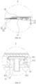
FIG. 3 is a side structural view of the battery module inFIG. 1 . -
FIG. 4 is a cross-sectional structural view at B-B inFIG. 3 . -
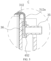
FIG. 5 is a partial enlarged structural view at C inFIG. 4 . -
FIG. 6 is a top structural view of the battery module inFIG. 1 . -
FIG. 7 is a cross-sectional structural diagram at D-D inFIG. 6 . -
FIG. 8 is a partial enlarged structural view at E inFIG. 7 . -
FIG. 9 is a partial enlarged structural view at F inFIG. 6 . -
FIG. 10 is a schematic structural diagram of a first end plate. -
FIG. 11 is a partial enlarged structural view at G inFIG. 10 . -
FIG. 12 is a top structural view of the first end plate inFIG. 10 . -
FIG. 13 is a partial enlarged structural view at H inFIG. 12 . -
FIG. 14 is a schematic structural diagram of a liquid cooling tube according to an embodiment of the present disclosure. - 100. Battery module; 10. Battery cell; 11. Top cover; 12. Pole; 20. Bus-bar; 30. Liquid cooling tube; 31. Liquid cooling tube body; 311. First liquid cooling tube section; 311a. First bent section; 311b. First end; 311c. Second end; 312. Second liquid cooling tube section; 312a. Second bent section; 312b. First end; 312c. Second end; 313. Connecting tube section; 313a. First end; 313b. Second end; 32. Thermal insulating layer; 33. Liquid inlet connector; 34. Liquid inlet collecting pipe; 35. Liquid outlet connector; 36. Liquid outlet collecting pipe; 40. Box; 41. First end plate; 411. First side; 412. Second side; 42. Second end plate; 43. First side plate; 44. Second side plate; 45. Limiting installation part; 451. First limiting part; 452. Second limiting part; 453. Flared part; 50. Lead-out pole base; 60. Lead-out pole.
- In order to make the above objects, features and advantages of the present disclosure more obvious and easy to understand, the specific implementations of the present disclosure will be described in detail below with reference to the accompanying drawings. In the following description, numerous specific details are set forth in order to provide a thorough understanding of the present disclosure. However, the present disclosure can be implemented in many other ways different from those described here. Those skilled in the art can make similar improvements without violating the connotation of the present disclosure. Therefore, the present disclosure is not limited by the specific embodiments disclosed below.
- It should be understood that in the description of the present disclosure, if the terms such as "center", "longitudinal", "transverse", "length", "width ", "thickness", "upper", "lower", "front", "back", "left", "right", "vertical", "horizontal", " top ", "bottom" , "inside", "outside", "clockwise", "counterclockwise", "axial", "radial", "circumferential" are used, the orientation or positional relationship indicated by these terms is based on the orientation or positional relationship shown in the drawings, and is only for the convenience of describing the present disclosure and simplifying the description, rather than indicating or implying that the device or element referred to must have the specific orientation or be constructed and operate in the specific orientation, and therefore cannot be construed as limitation on the present disclosure.
- In addition, if the terms such as "first" and "second" are used, these terms are used for descriptive purposes only and cannot be understood as indicating or implying the relative importance or implicitly indicating the quantity of the indicated technical features. Therefore, the features defined with "first" and "second" may explicitly or implicitly include at least one of these features. In the description of the present disclosure, if the term "a plurality of" is used, the meaning of "a plurality of" is at least two, such as two, three, etc., unless otherwise expressly and specifically indicated.
- In the present disclosure, unless otherwise expressly indicated and limited, if the terms such as "installing", "connected", "connecting", "fixing" are used, these terms should be interpreted in broad sense. For example, there can be a fixed connection or a detachable connection, or there can be integrated; there can be a mechanical connection or an electrical connection; there can be a direct connection or an indirect connection through an intermediate medium; or there can be internal communication between two components or interaction between two elements, unless otherwise expressly limited. Those of ordinary skill in the art can understand the specific meanings of the above terms in the present disclosure according to specific circumstances.
- In the present disclosure, if a first feature is "on" or "below" a second feature or there is similar descriptions, the meaning thereof may be that the first and second features are in direct contact, or the first and second features are in indirect contact through an intermediate medium, unless otherwise explicitly stated and limited. Furthermore, the first feature being "on", "above" and "over" the second feature may mean that the first feature is directly above or diagonally above the second feature, or simply means that the first feature is higher in level than the second feature. The first feature being "below", "under" and "beneath" the second feature may mean that the first feature is directly below or diagonally below the second feature, or simply means that the first feature is lower in level than the second feature.
- It should be noted that if an element is referred to as being "fixed to" or "disposed on" another element, it can be directly on the other element or there may be an intervening element. If an element is said to be "connected" to another element, it can be directly connected to the other element or there may also be an intervening element. The terms such as "vertical", "horizontal", "upper", "lower", "left", "right" and similar expressions, if used in the present disclosure, are for illustrative purposes only and are not meant to indicate exclusive implementation.
- Referring to
FIGS. 1 ,3 ,4 and6 , there is shown abattery module 100 according to an embodiment of the present disclosure. Thebattery module 100 includes at least twobattery cells 10, at least one bus-bar 20 and aliquid cooling tube 30. Specifically,FIG. 1 shows abattery module 100 loaded with twelvebattery cells 10. Thebattery cells 10 are rectangular batteries, and the twelvebattery cells 10 are arranged side by side in the same direction in such a way that their large surfaces (sides) match with each other (for example, are in contact with each other or maintain a preset gap therebetween). - Of course, in other embodiments, the
battery cell 10 may also be a cylindrical cell or the like. - In addition,
FIG. 1 also shows that the number of the bus-bars 20 is also twelve. Six of the bus-bars 20 are arranged in a line at one end of thebattery module 100 in the length direction, and each bus-bar 20 is electrically connected topositive poles 12 of twoadjacent battery cells 10. The remaining six bus-bars 20 are arranged in a line at the other end of thebattery module 100 in the length direction, and each bus-bar 20 is electrically connected tonegative poles 12 of twoadjacent battery cells 10. - Optionally, the electrical connection between the bus-
bars 20 and thepositive poles 12 and thenegative poles 12 may be welding or otherwise. - Continuing to refer to
FIGS. 7 and8 , each of thebattery cells 10 has a respectivetop cover 11; each of the bus-bars 20 is disposed above two adjacent top covers 11, and each of the bus-bars 20 is electrically connected to thepoles 12 provided on the two adjacent top covers 11. Theliquid cooling tube 30 is arranged on all the top covers 11 and cooperate with all the bus-bars 20 for heat transfer. - To sum up, implementing the technical solution of this embodiment will have the following beneficial effects. In the
battery module 100 of the above solution, by installing theliquid cooling tube 30 between the top covers 11 of thebattery cells 10 and the bus-bars 20, when the high-rate and large-capacity battery module 100 operates with large-current charging and discharging, which increases the current flowing through the bus-bar 20 and causes the heat generated by the bus-bar 20 to significantly increase, theliquid cooling tube 30 is communicated with an external cooling medium supply device which will input cooling medium to theliquid cooling tube 30, and the cooling medium can realize heat exchange with the bus-bars 20 through the wall of theliquid cooling tube 30. In this way, the high-temperature heat of the bus-bars 20 can be quickly absorbed and taken away by the cooling medium, realizing the cooling effect of the bus-bars 20 by theliquid cooling tube 30, well solving the problem of excessive heat generated by the bus-bars 20 in higher overcurrent scenarios, and improving the overcurrent capacity of the bus-bars 20. This solution does not require increasing the width and thickness of the bus-bar, does not take up too much installation space, does not limit the overcurrent capacity of the bus-bar 20 by the size, and does not need to use materials with better overcurrent capacity for the bus-bar 20, avoiding the problems of high processing costs and difficulties. - In actual work, in the large overcurrent scenarios with high-rate and large-capacity battery, the
liquid cooling tube 30 can actually achieve heat dissipation and cooling of the heat generating positions such as the bus-bars 20, the welding parts of thepoles 12 and the bus-bars 20, the welding parts of thepoles 12 and tabs inside the battery, and the welding parts of the tabs inside the battery and bare battery cells. - Please continue to refer to
FIGS. 1, 2 , and5 . In some embodiments, theliquid cooling tube 30 includes a liquidcooling tube body 31 and a thermal insulatinglayer 32. The thermal insulatinglayer 32 is installed on the outside of the liquidcooling tube body 31, and the thermallyconductive insulation layer 32 abuts the bus-bars 20. A flow passage is formed inside the liquidcooling tube body 31, and the cooling medium can flow in the flow passage, so that heat can be transferred with the bus-bars 20 through the tube wall of the liquidcooling tube body 31, so as to achieve cooling and heat dissipation of the bus-bars 20. - According to actual needs, the cooling medium may be, but is not limited to, any one of water, oil, or the like, or a mixture of two or more.
- The thermally
conductive insulation layer 32 installed on the outside of the liquidcooling tube body 31 is made of compressible materials with high thermal conductivity and good insulation effect. For example, thermally conductive silica gel is used in the embodiment, and in addition to assist rapid heat conduction to the liquidcooling tube body 31 from the bus-bars 20, it can ensure insulation protection to be formed between the bus-bars 20 and the liquidcooling tube body 31. - During actual manufacturing, under the action of tooling pressure, the bus-
bars 20 will form surface contact with the positive andnegative poles 12, and then the electrical connection is implemented through laser welding. Meanwhile, the thermal insulatinglayer 32 will be subjected to the pressure from the bus-bars 20, so as to form thermal conductive contact between theliquid cooling tube 30 and the bus-bars 20. Such a connection method is fast and simple, which helps improve production efficiency. - In the present disclosure, the heat dissipation of the bus-
bars 20 is assisted by theliquid cooling tube 30, and the core lies in the design of the heat exchange contact area between theliquid cooling tube 30 and the bus-bars 20. In some embodiments, the width of the liquidcooling tube body 31 ranges from 15mm to 48mm. If the width of the liquidcooling tube body 31 is small, the heat exchange contact area with the bus-bars 20 will be small, which will affect the cooling and heat dissipation performance of theliquid cooling tube 30 for the bus-bars 20; and if the width of the liquidcooling tube body 31 is too large, part of the width of the liquidcooling tube body 31 cannot contact the bus-bar 20, that is, it cannot participate in the heat transfer at all, resulting in excess width and heavy weight of the liquidcooling tube body 31 and increased costs due to increased consumables. By controlling the width of the liquidcooling tube body 31 within the range of 15 mm to 48 mm, the above problems can be avoided and the use requirements of the bus-bars 20 of different sizes can be met. - Furthermore, the liquid
cooling tube body 31 uses a flat tube. The flat tube has a first wide surface and a second wide surface that are opposite to each other. The first wide surface is in contact with the top covers 11, and the second wide surface is in contact with the bus-bars 20. After installation, it helps to reduce the overall height of thebattery module 100, reduces the installation space occupied, and facilitates the miniaturization design of thebattery module 100. - Optionally, a cross section of the flat tube may be any one of rectangular shape, elliptical shape, etc.
- Please continue to refer to
FIGS. 1 and14 . In addition, in some embodiments, the liquidcooling tube body 31 includes a first liquidcooling tube section 311, a second liquidcooling tube section 312 and a connectingtube section 313. Afirst end 313a of the connectingtube section 313 is communicated with afirst end 311b of the first liquidcooling tube section 311, and asecond end 313b of the connectingtube section 313 is communicated with afirst end 312b of the second liquidcooling tube section 312. For example, in this embodiment, the first liquidcooling tube section 311, the connectingtube section 313 and the second liquidcooling tube section 312 match to form a U-shaped or C-shaped structure. - The first liquid
cooling tube section 311 is arranged close to thepoles 12 at one end of thebattery cells 10, the second liquidcooling tube section 312 is arranged close to thepoles 12 at the other end of thebattery cells 10, and the connectingtube section 313 is arranged close to the edge of thebattery module 100. - Employing the U-shaped or C-shaped structural design for the liquid
cooling tube body 31 can not only prevent the first liquidcooling tube section 311, the second liquidcooling tube section 312 and the connectingtube section 313 from blocking parts such as explosion-proof valves in the middle of thebattery cells 10, but also shorten the length of the liquidcooling tube body 31 so as to reduce consumables and manufacturing costs. In addition, the first liquidcooling tube section 311 and the second liquidcooling tube section 312 are arranged closer to thepoles 12 at both ends of thebattery cells 10 in the length direction, making it easier to form reliable heat transfer contact with the bus-bars 20 and conducive to reducing the size of the bus-bars 20. - It can be understood that when
multiple battery cells 10 are arranged side by side, a row of multiple poles corresponding to the first liquidcooling tube section 311 and a row of multiple poles corresponding to the second liquidcooling tube section 312 are arranged in a positive and negative alternating manner to achieve series connection of thebattery cells 10. - Please continue to refer to
FIGS. 1 to 5 . On the basis of the above embodiments, theliquid cooling tube 30 also includes aliquid inlet connector 33, a liquidinlet collecting pipe 34, aliquid outlet connector 35 and a liquidoutlet collecting pipe 36. Asecond end 311c of the first liquidcooling tube section 311 is communicated with the liquidinlet collecting pipe 34, theliquid inlet connector 33 is communicated with the liquidinlet collecting pipe 34, and asecond end 312c of the second liquidcooling tube section 312 is communicated with the liquidoutlet collecting pipe 36, and the liquidoutlet collecting pipe 36 is communicated with theliquid outlet connector 35. The cooling medium is conveniently input from theliquid inlet connector 33, and then flows into the liquidcooling tube body 31 through the liquidinlet collecting pipe 34. After the cooling medium completes heat transfer with the bus-bars 20, it further flows to theliquid outlet connector 35 through the liquidoutlet collecting pipe 36, and is finally discharged from theliquid outlet connector 35 and returned to the cooling medium supply device, realizing recycling of the cooling medium. - Please continue to refer to
FIGS. 1 ,3 and6 . In addition, in some embodiments, thebattery module 100 further includes abox 40. Thebox 40 includes afirst end plate 41, asecond end plate 42, afirst side plate 43 and asecond side plate 44. Thefirst end plate 41, thefirst side plate 43, thesecond end plate 42 and thesecond side plate 44 are connected end-to-end and define an installation cavity, and all thebattery cells 10 are installed in the installation cavity. Further, thebox 40 may also include a bottom plate, which loads and supports thefirst end plate 41, thesecond end plate 42, thefirst side plate 43 and thesecond side plate 44, so that thefirst end plate 41, thesecond end plate 42, thefirst side plate 43 and thesecond side plate 44 can be erected on the bottom plate and connected end-to-end. When all thebattery cells 10 are inserted into the installation cavity, they will be subjected to the pre-tightening effect of thefirst end plate 41, thesecond end plate 42, thefirst side plate 43 and thesecond side plate 44, forming a stable installation and ensuring that thebattery cell 10 is not prone to loosening or falling off. - After installation, the positive and negative poles of the
battery cells 10, the top covers 11 and the bus-bars 20 are all located on the upper open side of thebox 40 to facilitate connection operations. - Optionally, the
first end plate 41, thesecond end plate 42, thefirst side plate 43 and thesecond side plate 44 can be assembled and fixed through any one of methods such as welding, screw connection, snap connection, etc., which can be flexibly selected according to actual needs. - Please continue to refer to
FIGS. 2 ,3 ,5 , and9 to 13 . Further, thefirst end plate 41 or thesecond end plate 42 is recessed to form two limitinginstallation parts 45, and thesecond end 311c of the first liquidcooling tube section 311 is formed with a firstbent section 311a that is bent toward a corresponding one of the two limitinginstallation parts 45. The liquidinlet collecting pipe 34 is installed at an extension part of the firstbent section 311a that is oriented toward the corresponding limitinginstallation part 45 and is in limiting fit with the limitinginstallation part 45; thesecond end 312c of the second liquidcooling tube section 312 is formed with a secondbent section 312a that is bent toward another corresponding one of the limitinginstallation parts 45, and the liquidoutlet collecting pipe 36 is installed at an extension part of the secondbent section 312a that is oriented toward the other corresponding limitinginstallation part 45 and is in limiting fit with the other limitinginstallation part 45. Therefore, after installation, the limitinginstallation parts 45 can effectively restrict the degree of freedom of the liquidinlet collecting pipe 34 and the liquidoutlet collecting pipe 36, thereby achieving the effect of preventing the loosening or even falling of theliquid cooling tube 30, and improving the installation reliability of theliquid cooling tube 30. - Specifically, in some embodiments, each of the two limiting
installation parts 45 includes a first limitingpart 451, and the first limitingpart 451 is adapted to fit a part of an outer tube wall contour of the liquidinlet collecting pipe 34 and a part of an outer tube wall contour of the liquidoutlet collecting pipe 36. - For example, taking the installation structure of the
first end plate 41, the liquidinlet collecting pipe 34 and theliquid inlet connector 33 as an example, the upper end surface of thefirst end plate 41 is recessed inward to form a groove, and at least one side wall of the groove is provided with the first limitingparts 451. After the liquidinlet collecting pipe 34 and theliquid inlet connector 33 are inserted into the groove from top to bottom, the left and right side walls of the liquidinlet collecting pipe 34 are precisely engaged with the two first limitingparts 451 in one-to-one correspondence, so that the horizontal movement freedom of the liquidinlet collecting pipe 34 and theliquid inlet connector 33 is constrained, and when the counterpart (i.e., a plug of the cooling liquid supply device) is horizontally inserted and connected with the liquid inlet joint 33, it can ensure that theliquid cooling tube 30 is fixed, thereby avoiding damage to theliquid inlet connector 33 and preventing deformation of theliquid cooling tube 30. - For example, in this embodiment, the first limiting
part 451 is designed as a semicircular groove, the liquidinlet collecting pipe 34 uses a flat tube with an elliptical cross-section, and the arc-shaped facet of the liquidinlet collecting pipe 34 can be precisely fit and engaged with the semicircular groove, thereby well restricting the freedom of movement of the liquidinlet collecting pipe 34 in back and forth and left and right. - Furthermore, the
limit installation part 45 further includes a second limitingpart 452, and the second limitingpart 452 abuts a tube end wall of the liquidinlet collecting pipe 34 and a tube end wall of the liquidoutlet collecting pipe 36. For example, the second limitingpart 452 is a step structure formed on at least one side wall of the groove, and after the liquidinlet collecting pipe 34 is installed in the groove, its lower tube end wall can be in precise lap-joint with the step structure. In this case, the step structure can apply a limit in the -Z axis direction to the liquidinlet collecting pipe 34. At the same time, the bus-bars 20, after being installed and fixed, will press against the upper surface of theliquid cooling tube 30, synchronously applying a limit in the +Z axis direction to theliquid cooling tube 30, completely limiting the degree of freedom in the Z axis direction of theliquid cooling tube 30, ensuring the stable installation of theliquid cooling tube 30 and preventing deformation of theliquid cooling tube 30 due to battery expansion or stress during subsequent maintenance. - Furthermore, each of the two limiting
installation parts 45 also includes a flaredpart 453. Thefirst end plate 41 or thesecond end plate 42 has afirst side 411 and asecond side 412 opposite each other in the thickness direction. The width of the flaredpart 453 transitions incrementally in the direction from thefirst side 411 to thesecond side 412; theliquid inlet connector 33 extends from a corresponding one of two flaredparts 453 of the two limitinginstallation parts 45 and theliquid outlet connector 35 extends from another corresponding one of the two flaredparts 453. During actual installation, if the size of the counterpart (i.e., the plug of the cooling liquid supply device) is of compact size, the flaredpart 453 can appropriately increase the space for movement and operation when the counterpart is plugged in, facilitating the installation operation. - In some other embodiments, the
battery module 100 further includes at least two lead-outelectrode bases 50 and at least two lead-outelectrodes 60. The lead-outelectrode bases 50 are installed on thebox 40, and the lead-outelectrodes 60 are installed on the lead-outelectrode bases 50 in one-to-one correspondence, and the lead-outelectrodes 60 are electrically connected to all the bus-bars 20. The bus-bars 20 of asingle battery module 100 are electrically connected to the lead-outelectrodes 60 to achieve current convergence. On this basis, the lead-outelectrodes 60 can also realize electrical connection betweendifferent battery modules 100. - In summary, the present disclosure also provides an energy storage device, which includes the
battery module 100 as described in any of the above embodiments. - The various technical features of the embodiments described above can be combined in any way. To simplify the description, not all possible combinations of the technical features in the above-described embodiments are described. However, all the combinations of these technical features should be considered to be within the scope of the present specification as long as there is no contradiction in the combinations.
- The embodiments described above only represent several implementations of the present disclosure, and their descriptions are relatively specific and detailed, but they should not be construed as limiting the scope of the present disclosure. It should be noted that several modifications and improvements can be made by those of ordinary skill in the art without departing from the concept of the present disclosure, and these all fall within the protection scope of the present disclosure. Therefore, the protection scope of the present disclosure should be defined by the appended claims.
Claims (11)
- A battery module (100), comprising:at least two battery cells (10), each of the at least two battery cells (10) having a respective top cover (11);at least one bus-bar (20), each bus-bar of the at least one bus-bar (20) being disposed above two respective adjacent top covers and electrically connected to poles (12) disposed on the two adjacent top covers; anda liquid cooling tube (30), arranged above all the top covers and cooperating with the at least one bus-bar (20) for heat transfer.
- The battery module (100) according to claim 1, wherein the liquid cooling tube (30) comprises a liquid cooling tube body (31) and a thermal insulating layer (33), the thermal insulating layer (33) is installed on an outside of the liquid cooling tube body (31), and the thermal insulating layer (33) abuts the at least one bus-bar (20).
- The battery module (100) according to claim 2, wherein a width of the liquid cooling tube body (31) ranges from 15 mm to 48 mm.
- The battery module (100) according to claim 2, wherein the liquid cooling tube body (31) is a flat tube, the flat tube has a first wide surface and a second wide surface opposite to each other, the first wide surface abuts the top cover of each of the at least two battery cells (11), and the second wide surface abuts the at least one bus-bar (20).
- The battery module (100) according to claim 2, wherein the liquid cooling tube body (31) comprises a first liquid cooling tube section (311), a second liquid cooling tube section (312) and a connecting tube section (313), a first end (313a) of the connecting tube section (313) is communicated with a first end (311b) of the first liquid cooling tube section (311), a second end (313b) of the connecting tube section (313) is communicated with a first end (312b) of the second liquid cooling tube section (312), the first liquid cooling tube section (311) is arranged close to poles (12) at one end of the battery cells (10), the second liquid cooling tube section (312) is arranged close to poles (12) at the other end of the battery cells (10), and the connecting tube section (313) is arranged close to an edge of the battery module (100).
- The battery module (100) according to claim 5, wherein the liquid cooling tube further comprises a liquid inlet connector (33), a liquid inlet collecting pipe (34), a liquid outlet connector (35) and a liquid outlet collecting pipe (36), a second end (311c) of the first liquid cooling tube section (311) is communicated with the liquid inlet collecting pipe (34), the liquid inlet connector (35) is communicated with the liquid inlet collecting pipe (34), and a second end (312c) of the second liquid cooling tube section (312) is communicated with the liquid outlet collecting pipe (36), and the liquid outlet collecting pipe (36) is communicated with the liquid outlet connector (35).
- The battery module (100) according to claim 6, wherein the battery module (110) further comprises a box (40), the box (40) comprises a first end plate (41), a second end plate (42), a first side plate (43) and a second side plate (44), the first end plate (41), the first side plate (43), the second end plate (42) and the second side plate (44) are connected end-to-end and define an installation cavity, and all the battery cells (10) are installed inside the installation cavity;the first end plate (41) or the second end plate (42) is recessed to form two limiting installation parts (45), and the second end (311c) of the first liquid cooling tube section (311) is formed with a first bent section (311a) that is bent toward a corresponding one of the two limiting installation parts (45), and the liquid inlet collecting pipe (34) is installed at an extension part of the first bent section (311a) that is oriented towards the corresponding one of the limiting installation parts (45), and the liquid inlet collecting pipe (34) is in limiting fit with the limiting installation part (45); andthe second end (312c) of the second liquid cooling tube section (312) is formed with a second bent section (312a) that is bent toward another corresponding one of the two limiting installation parts (45), and the liquid outlet collecting pipe (36) is installed at an extension part of the second bent section (312a) that is oriented toward the other corresponding limiting installation part (45) and the liquid outlet collecting pipe (36) is in limiting fit with the other corresponding limiting installation part (45).
- The battery module (100) according to claim 7, wherein each of the two limiting installation parts (45) comprises a first limiting part (451), the first limiting part (451) is adapted to fit a part of an outer tube wall contour of the liquid inlet collecting pipe (34) and a part of an outer tube wall contour of the liquid outlet collecting pipe (36).
- The battery module (100) according to claim 7, wherein each of the two limiting installation parts (45) further comprises a second limiting part (452), and the second limiting part (452) abuts a tube end wall of the liquid inlet collecting pipe (34) and a tube end wall of the liquid outlet collecting pipe (36).
- The battery module (100) according to claim 7, wherein each of the two limiting installation parts (45) further comprises a flared part (453), and the first end plate (41) or the second end plate (42) has a first side (411) and a second side (412) opposite each other in a thickness direction, and a width of the flared part (453) transitions incrementally in a direction from the first side (411) to the second side (412); and
the liquid inlet connector (33) extends from a corresponding one of two flared parts (453) of the two limiting installation parts (45) and the liquid outlet connector (35) extends from another corresponding one of the two flared parts (45). - An energy storage device, comprising a battery module (100) according to any one of claims 1 to 10.
Applications Claiming Priority (1)
| Application Number | Priority Date | Filing Date | Title |
|---|---|---|---|
| CN202310718976.1A CN116454468B (en) | 2023-06-16 | 2023-06-16 | Battery module and energy storage device |
Publications (1)
| Publication Number | Publication Date |
|---|---|
| EP4478489A1 true EP4478489A1 (en) | 2024-12-18 |
Family
ID=87128862
Family Applications (1)
| Application Number | Title | Priority Date | Filing Date |
|---|---|---|---|
| EP24173570.3A Pending EP4478489A1 (en) | 2023-06-16 | 2024-04-30 | Battery module and energy storage device |
Country Status (4)
| Country | Link |
|---|---|
| US (1) | US12100942B1 (en) |
| EP (1) | EP4478489A1 (en) |
| CN (1) | CN116454468B (en) |
| WO (1) | WO2024255282A1 (en) |
Families Citing this family (3)
| Publication number | Priority date | Publication date | Assignee | Title |
|---|---|---|---|---|
| CN116454468B (en) | 2023-06-16 | 2023-09-12 | 深圳海辰储能控制技术有限公司 | Battery module and energy storage device |
| CN121359293A (en) * | 2024-03-01 | 2026-01-16 | 宁德时代新能源科技股份有限公司 | Batteries, electrical devices and energy storage devices |
| CN118248996B (en) * | 2024-05-23 | 2024-09-13 | 天津力神新能源科技有限公司 | Modular heat exchange plates, heat exchange systems, vehicle-mounted battery systems and energy storage battery systems |
Citations (3)
| Publication number | Priority date | Publication date | Assignee | Title |
|---|---|---|---|---|
| US20130280574A1 (en) * | 2012-04-19 | 2013-10-24 | Sb Limotive Co., Ltd. | Battery pack |
| CN216793932U (en) * | 2022-02-25 | 2022-06-21 | 重庆金康动力新能源有限公司 | Busbar subassembly and battery module |
| CN115954622A (en) * | 2022-12-22 | 2023-04-11 | 广汽埃安新能源汽车股份有限公司 | A bus bar, an electric control system and a battery pack |
Family Cites Families (18)
| Publication number | Priority date | Publication date | Assignee | Title |
|---|---|---|---|---|
| CN201758914U (en) | 2010-06-01 | 2011-03-16 | 张焕兴 | Multifunctional cane |
| KR101217564B1 (en) * | 2010-08-16 | 2013-01-02 | 주식회사 엘지화학 | Voltage Sensing Assembly and Battery Module Employed with the Same |
| CN201906713U (en) | 2010-12-16 | 2011-07-27 | 厦门欣意盛陶瓷原料有限公司 | High-frequency vibrating screen |
| JP2012227164A (en) * | 2012-07-20 | 2012-11-15 | Sanyo Electric Co Ltd | Battery system |
| CN206422183U (en) * | 2016-12-22 | 2017-08-18 | 宁波比亚迪汽车有限公司 | Battery modules cover plate assembly, battery modules and battery bag |
| CN212934752U (en) | 2020-06-24 | 2021-04-09 | 惠州亿纬锂能股份有限公司 | A battery module, chassis assembly and energy storage device |
| WO2022011513A1 (en) * | 2020-07-13 | 2022-01-20 | 威睿电动汽车技术(宁波)有限公司 | Battery module and vehicle |
| CN213124634U (en) * | 2020-09-04 | 2021-05-04 | 欣旺达惠州动力新能源有限公司 | Insulation system, battery package and car |
| CN212676355U (en) | 2020-09-11 | 2021-03-09 | 珠海银隆电器有限公司 | Heat dissipation structure, battery module and heat dissipation system |
| CN214411453U (en) * | 2021-01-21 | 2021-10-15 | 江苏塔菲尔动力系统有限公司 | Battery module and battery package of solar heat protection diffusion |
| CN115842189B (en) * | 2021-11-05 | 2023-12-15 | 宁德时代新能源科技股份有限公司 | Battery cooling structure, battery and power utilization device |
| CN216698632U (en) * | 2021-12-29 | 2022-06-07 | 蜂巢能源科技股份有限公司 | Supporting mechanism, busbar assembly and battery module |
| US12136721B2 (en) * | 2022-03-11 | 2024-11-05 | Caterpillar Inc. | Battery busbar temperature management system |
| CN217589140U (en) * | 2022-06-28 | 2022-10-14 | 中创新航科技股份有限公司 | battery unit |
| CN115579552A (en) | 2022-10-31 | 2023-01-06 | 广汽埃安新能源汽车股份有限公司 | Battery module |
| CN219067138U (en) * | 2022-12-13 | 2023-05-23 | 蜂巢能源科技股份有限公司 | battery module |
| US11784369B1 (en) * | 2023-03-10 | 2023-10-10 | Dimaag-Ai, Inc. | Swappable battery modules comprising immersion-thermally controlled prismatic battery cells and methods of fabricating thereof |
| CN116454468B (en) * | 2023-06-16 | 2023-09-12 | 深圳海辰储能控制技术有限公司 | Battery module and energy storage device |
-
2023
- 2023-06-16 CN CN202310718976.1A patent/CN116454468B/en active Active
-
2024
- 2024-02-06 WO PCT/CN2024/076260 patent/WO2024255282A1/en not_active Ceased
- 2024-04-24 US US18/644,930 patent/US12100942B1/en active Active
- 2024-04-30 EP EP24173570.3A patent/EP4478489A1/en active Pending
Patent Citations (3)
| Publication number | Priority date | Publication date | Assignee | Title |
|---|---|---|---|---|
| US20130280574A1 (en) * | 2012-04-19 | 2013-10-24 | Sb Limotive Co., Ltd. | Battery pack |
| CN216793932U (en) * | 2022-02-25 | 2022-06-21 | 重庆金康动力新能源有限公司 | Busbar subassembly and battery module |
| CN115954622A (en) * | 2022-12-22 | 2023-04-11 | 广汽埃安新能源汽车股份有限公司 | A bus bar, an electric control system and a battery pack |
Also Published As
| Publication number | Publication date |
|---|---|
| US12100942B1 (en) | 2024-09-24 |
| CN116454468A (en) | 2023-07-18 |
| CN116454468B (en) | 2023-09-12 |
| WO2024255282A1 (en) | 2024-12-19 |
Similar Documents
| Publication | Publication Date | Title |
|---|---|---|
| EP4478489A1 (en) | Battery module and energy storage device | |
| CN211480235U (en) | battery pack | |
| CN217182265U (en) | Battery and electric equipment | |
| CN219106281U (en) | A liquid cooling system and battery module | |
| CN115911655A (en) | A liquid cooling system and battery module | |
| CN116526015A (en) | Battery Module and Energy Storage System | |
| CN115692920A (en) | Liquid cooling battery module | |
| WO2024255264A1 (en) | Liquid cooling device, battery module, and energy storage system | |
| CN114335805A (en) | A power battery module with integrated liquid cold plate assembly | |
| CN108155311A (en) | A kind of lithium-ion-power cell liquid chill group | |
| CN116169415A (en) | Battery case and battery pack | |
| CN115603002A (en) | An electrical bus, a single battery and a battery pack | |
| CN205680712U (en) | A kind of battery modules | |
| CN115663383A (en) | Battery module and battery pack | |
| WO2023155207A1 (en) | Battery, electrical device, and battery preparation method and device | |
| CN220731621U (en) | Battery module | |
| CN218334008U (en) | Heat dissipation casing and battery module | |
| CN218731384U (en) | Monomer electric core and battery module of integrated thermal management structure | |
| CN216671797U (en) | Power battery module of integrated liquid cooling board subassembly | |
| CN217426892U (en) | Battery cell structure and battery cell module | |
| CN223297001U (en) | Single battery and electricity storage device | |
| CN220209085U (en) | Battery pack | |
| CN220400805U (en) | Battery pack, power device and energy storage device | |
| CN219626847U (en) | High-rate battery pack | |
| CN219476843U (en) | Battery pack |
Legal Events
| Date | Code | Title | Description |
|---|---|---|---|
| PUAI | Public reference made under article 153(3) epc to a published international application that has entered the european phase |
Free format text: ORIGINAL CODE: 0009012 |
|
| STAA | Information on the status of an ep patent application or granted ep patent |
Free format text: STATUS: THE APPLICATION HAS BEEN PUBLISHED |
|
| AK | Designated contracting states |
Kind code of ref document: A1 Designated state(s): AL AT BE BG CH CY CZ DE DK EE ES FI FR GB GR HR HU IE IS IT LI LT LU LV MC ME MK MT NL NO PL PT RO RS SE SI SK SM TR |
|
| RAP1 | Party data changed (applicant data changed or rights of an application transferred) |
Owner name: HITHIUM TECH HK LIMITED |
|
| STAA | Information on the status of an ep patent application or granted ep patent |
Free format text: STATUS: REQUEST FOR EXAMINATION WAS MADE |
|
| 17P | Request for examination filed |
Effective date: 20250618 |
|
| GRAP | Despatch of communication of intention to grant a patent |
Free format text: ORIGINAL CODE: EPIDOSNIGR1 |
|
| STAA | Information on the status of an ep patent application or granted ep patent |
Free format text: STATUS: GRANT OF PATENT IS INTENDED |
|
| INTG | Intention to grant announced |
Effective date: 20251211 |
|
| GRAS | Grant fee paid |
Free format text: ORIGINAL CODE: EPIDOSNIGR3 |
|
| GRAA | (expected) grant |
Free format text: ORIGINAL CODE: 0009210 |
|
| STAA | Information on the status of an ep patent application or granted ep patent |
Free format text: STATUS: THE PATENT HAS BEEN GRANTED |