EP4478486A1 - Battery module, and battery module manufacturing method - Google Patents
Battery module, and battery module manufacturing method Download PDFInfo
- Publication number
- EP4478486A1 EP4478486A1 EP23812019.0A EP23812019A EP4478486A1 EP 4478486 A1 EP4478486 A1 EP 4478486A1 EP 23812019 A EP23812019 A EP 23812019A EP 4478486 A1 EP4478486 A1 EP 4478486A1
- Authority
- EP
- European Patent Office
- Prior art keywords
- cell block
- block assembly
- battery module
- bottom plate
- sidewall
- Prior art date
- Legal status (The legal status is an assumption and is not a legal conclusion. Google has not performed a legal analysis and makes no representation as to the accuracy of the status listed.)
- Pending
Links
Images


Classifications
-
- H—ELECTRICITY
- H01—ELECTRIC ELEMENTS
- H01M—PROCESSES OR MEANS, e.g. BATTERIES, FOR THE DIRECT CONVERSION OF CHEMICAL ENERGY INTO ELECTRICAL ENERGY
- H01M50/00—Constructional details or processes of manufacture of the non-active parts of electrochemical cells other than fuel cells, e.g. hybrid cells
- H01M50/20—Mountings; Secondary casings or frames; Racks, modules or packs; Suspension devices; Shock absorbers; Transport or carrying devices; Holders
- H01M50/204—Racks, modules or packs for multiple batteries or multiple cells
- H01M50/207—Racks, modules or packs for multiple batteries or multiple cells characterised by their shape
- H01M50/211—Racks, modules or packs for multiple batteries or multiple cells characterised by their shape adapted for pouch cells
-
- H—ELECTRICITY
- H01—ELECTRIC ELEMENTS
- H01M—PROCESSES OR MEANS, e.g. BATTERIES, FOR THE DIRECT CONVERSION OF CHEMICAL ENERGY INTO ELECTRICAL ENERGY
- H01M10/00—Secondary cells; Manufacture thereof
- H01M10/60—Heating or cooling; Temperature control
- H01M10/61—Types of temperature control
- H01M10/613—Cooling or keeping cold
-
- H—ELECTRICITY
- H01—ELECTRIC ELEMENTS
- H01M—PROCESSES OR MEANS, e.g. BATTERIES, FOR THE DIRECT CONVERSION OF CHEMICAL ENERGY INTO ELECTRICAL ENERGY
- H01M10/00—Secondary cells; Manufacture thereof
- H01M10/60—Heating or cooling; Temperature control
- H01M10/64—Heating or cooling; Temperature control characterised by the shape of the cells
- H01M10/647—Prismatic or flat cells, e.g. pouch cells
-
- H—ELECTRICITY
- H01—ELECTRIC ELEMENTS
- H01M—PROCESSES OR MEANS, e.g. BATTERIES, FOR THE DIRECT CONVERSION OF CHEMICAL ENERGY INTO ELECTRICAL ENERGY
- H01M10/00—Secondary cells; Manufacture thereof
- H01M10/60—Heating or cooling; Temperature control
- H01M10/65—Means for temperature control structurally associated with the cells
- H01M10/653—Means for temperature control structurally associated with the cells characterised by electrically insulating or thermally conductive materials
-
- H—ELECTRICITY
- H01—ELECTRIC ELEMENTS
- H01M—PROCESSES OR MEANS, e.g. BATTERIES, FOR THE DIRECT CONVERSION OF CHEMICAL ENERGY INTO ELECTRICAL ENERGY
- H01M10/00—Secondary cells; Manufacture thereof
- H01M10/60—Heating or cooling; Temperature control
- H01M10/65—Means for temperature control structurally associated with the cells
- H01M10/655—Solid structures for heat exchange or heat conduction
- H01M10/6554—Rods or plates
-
- H—ELECTRICITY
- H01—ELECTRIC ELEMENTS
- H01M—PROCESSES OR MEANS, e.g. BATTERIES, FOR THE DIRECT CONVERSION OF CHEMICAL ENERGY INTO ELECTRICAL ENERGY
- H01M50/00—Constructional details or processes of manufacture of the non-active parts of electrochemical cells other than fuel cells, e.g. hybrid cells
- H01M50/20—Mountings; Secondary casings or frames; Racks, modules or packs; Suspension devices; Shock absorbers; Transport or carrying devices; Holders
- H01M50/233—Mountings; Secondary casings or frames; Racks, modules or packs; Suspension devices; Shock absorbers; Transport or carrying devices; Holders characterised by physical properties of casings or racks, e.g. dimensions
- H01M50/24—Mountings; Secondary casings or frames; Racks, modules or packs; Suspension devices; Shock absorbers; Transport or carrying devices; Holders characterised by physical properties of casings or racks, e.g. dimensions adapted for protecting batteries from their environment, e.g. from corrosion
-
- Y—GENERAL TAGGING OF NEW TECHNOLOGICAL DEVELOPMENTS; GENERAL TAGGING OF CROSS-SECTIONAL TECHNOLOGIES SPANNING OVER SEVERAL SECTIONS OF THE IPC; TECHNICAL SUBJECTS COVERED BY FORMER USPC CROSS-REFERENCE ART COLLECTIONS [XRACs] AND DIGESTS
- Y02—TECHNOLOGIES OR APPLICATIONS FOR MITIGATION OR ADAPTATION AGAINST CLIMATE CHANGE
- Y02E—REDUCTION OF GREENHOUSE GAS [GHG] EMISSIONS, RELATED TO ENERGY GENERATION, TRANSMISSION OR DISTRIBUTION
- Y02E60/00—Enabling technologies; Technologies with a potential or indirect contribution to GHG emissions mitigation
- Y02E60/10—Energy storage using batteries
Definitions
- the present invention relates to a battery module and a method for manufacturing the same, and more particularly, to a battery module in which a component welding part of a cooling plate, etc., is prevented from being ruptured during insertion and assembly of a cell block assembly, or a component welding part such as a cooling plate, etc., is prevented from being ruptured when a swelling phenomenon of the battery module occurs as the battery module is used for a long time to prevent the battery module from being defective, thereby implementing remarkably excellent concept products, and a method for manufacturing the same.
- lithium secondary batteries such as lithium ion batteries and lithium ion polymer batteries having advantages such as high energy density, discharge voltage, and output stability.
- the secondary batteries are classified into cylindrical batteries and prismatic batteries, in which an electrode assembly is embedded in a cylindrical or prismatic metal can, and pouch-type batteries, in which an electrode assembly is embedded in a pouch-type case made of an aluminum laminate sheet according to shapes of battery cases.
- an operating voltage of a unit cell i.e., a unit battery cell is about 2.5 V to about 4.2 V.
- a plurality of individual battery cells are connected to form a secondary battery module, and a plurality of battery modules are assembled to form a battery pack.
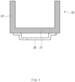
- FIG. 1 is a cross-sectional view illustrating a portion of a frame in a battery module according to a related art.
- FIG. 2 is a cross-sectional view illustrating a state in which a cell block assembly is inserted into the frame of FIG. 1 .
- a cell block assembly 10 configured by stacking a plurality of battery cells, which are manufactured as a pouch-type secondary battery by a predetermined number is mounted in a frame 20 having a 'U'-shaped cross-section, and the frame 20 is provided so that an upper side thereof is opened, and both sides thereof face a bottom surface of the cell block assembly 10.
- a top plate may be coupled to the opened upper side of the frame through brazing, and an end plate may be coupled to each of front and rear sides of the frame to generally provide a battery module having a rectangular parallelepiped shape.
- a cooling plate 30 in which a coolant is circulated to cool the block assembly 10 and the frame 20 may be coupled through the brazing welding.
- a sidewall of the frame may be spread to both sides B and B' , and the cell block assembly may be inserted while moving in a downward direction D.
- a phenomenon in which a shape of the bottom part of the frame is convexly bent upward may occur.
- a brazing-welding part W of the cooling plate mounted under the bottom part of the frame is ruptured (or damaged).
- the present invention has been made to solve the above problem, and an object of the present invention is to provide a battery module in which a component welding part of a cooling plate, etc., is prevented from being ruptured during insertion and assembly of a cell block assembly, or a component welding part such as a cooling plate, etc., is prevented from being ruptured when a swelling phenomenon of the battery module occurs as the battery module is used for a long time to prevent the battery module from being defective, thereby implementing remarkably excellent concept products, and a method for manufacturing the same.
- the battery module according to the present invention includes a cell block assembly that is an assembly of a plurality of cells, a bottom plate disposed on one surface of the cell block assembly, a frame configured to surround the other surface and a side surface of the cell block assembly, and an end plate disposed on each of front and rear surfaces of the cell block assembly.
- the battery module may further include a cooling plate coupled to one surface of the bottom plate at one side of the bottom plate.
- the cooling plate may be coupled to the one surface of the bottom plate through brazing welding.
- the frame may include a ceiling part configured to surround the other surface of the cell block assembly, and a sidewall configured to surround the side surface of the cell block assembly.
- the ceiling part and the sidewall may be integrated with each other.
- One end of the sidewall and both ends of the bottom plate may be coupled to each other through welding.
- the sidewall may include a first sidewall facing the cell block assembly, and a second sidewall connected to the first sidewall in a stepped shape at one side of the first sidewall to extend in a direction of the one side of the first sidewall.
- the bottom plate may include a first plate part facing the cell block assembly to extend in a direction parallel to one surface of the cell block assembly, and a second plate part extending from each of both ends of the first plate part in a direction away from the cell block assembly.
- An end of the second sidewall and an end of the second plate part may be coupled to each other through welding (W).
- the battery module may further include an insulating film disposed between the frame and the cell block assembly.
- the insulating film may include a horizontal part disposed between the ceiling part and the cell block assembly, and a vertical part disposed between the sidewall and the cell block assembly, wherein the horizontal part and the vertical part may be integrated with each other.
- the battery module may further include a thermal resin disposed between the other surface of the bottom plate and one surface of the cell block assembly.
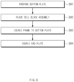
- a method for manufacturing a battery module according to the present invention includes a process (S01) of preparing a bottom plate having one surface to which a cooling plate is coupled, a process (S02) of placing a cell block assembly, which is an assembly of a plurality of cells, on the other surface of the bottom plate, a process (S03) of coupling a frame to the bottom plate to surround the other surface and a side surface of the cell block assembly, and a process (S04) of coupling an end plate to each of front and rear surfaces of the cell block assembly.
- the process of coupling the frame to the bottom plate may include a process of coupling the frame, to which an insulating sheet is coupled to an inner surface thereof, to the bottom plate.
- the process (S02) of the placing the cell block assembly may include a process of placing the cell block assembly on the other surface of the bottom plate in a state in which a thermal resin is disposed between the cell block assembly and the bottom plate.
- the process (S02) of the placing the cell block assembly may include a process of placing the cell block assembly on the other surface of the bottom plate in a state in which a thermal resin is disposed between the cell block assembly and the bottom plate.
- the component welding part of the cooling plate, etc. may be prevented from being ruptured, or the component welding part such as the cooling plate, etc., may be prevented from being ruptured when the swelling phenomenon of the battery module occurs as the battery module is used for a long time to prevent the battery module from being defective, thereby implementing the remarkably excellent concept products.
- FIG. 3 is an exploded perspective view of a battery module according to Embodiment 1 of the present invention.
- FIG. 4 is a cross-sectional view illustrating a manner in which the battery module is assembled according to Embodiment 1 of the present invention.
- FIG. 5 is a cross-sectional view illustrating a state in which the battery module is assembled according to Embodiment 1 of the present invention.
- a battery module according to Embodiment 1 of the present invention may include a cell block assembly 110, a bottom plate 140, a frame 120, and an end plate 150.
- the battery module may further include a cooling plate 130.
- the cell block assembly 110 may be an assembly of a plurality of battery cells.
- the battery module may be a cell assembly configured by stacking a plurality of battery cells manufactured as a pouch-type secondary battery by a predetermined number.
- the bottom plate 140 may be a component disposed on one surface of the cell block assembly 110.
- one surface may be, for example, a bottom surface of the cell block assembly.
- the bottom plate 140 may have a simple flat plate shape or may be partially deformed from the flat plate shape.
- the bottom plate 140 may include a first plate part 141 and a second plate part 142.
- the first plate part 141 may be a portion that faces the cell block assembly 110 and extends in a direction parallel to one surface of the cell block assembly 110. Referring to FIG. 5 , the direction parallel to the one surface of the cell block assembly 110 may mean a horizontal direction.
- the first plate part 141 may be a portion extending from the bottom plate 140 in a horizontal direction parallel to the one surface of the cell block assembly 110.
- the second plate part 142 may be a portion extending from both ends of the first plate part 141 in a direction away from the cell block assembly 110.
- the direction away from the cell block assembly 110 may be a vertically downward direction. That is, the second plate part 142 may be a portion extending vertically from each of both the ends of the horizontally extending first plate part 141 to extend downward.
- Such a shape may have an advantage of increasing in cooling area.
- the frame 120 may be a structure surrounding the other surface and a side surface of the cell block assembly 110.
- the other surface may mean a top surface of the cell block assembly 110. That is, the frame 120 may be a structure surrounding the top and side surfaces of the cell block assembly 110.
- the frame 120 has a shape extending in a longitudinal direction L of the cell block assembly 110, and a cross-section of the frame 120 may have a shape such as an inverted U shape (reverse u shape).
- the frame 120 may include a ceiling part 121 surrounding the other surface of the cell block assembly 110 and a sidewall 122 surrounding the side surface of the cell block assembly 110.
- the ceiling part 121 and the sidewall 122 may be integrated with each other.
- the battery module according to Embodiment 1 of the present invention may be formed in a manner in which the bottom plate 140 is coupled to the one open side of the frame 120 by brazing welding.
- the frame may be coupled to the bottom plate 140 by welding, and specifically, one end of the sidewall and both the ends of the bottom plate 140 may be coupled by welding.
- the one side may mean, for example, a lower side. That is, the bottom plate may be coupled to the open lower side of the frame by the brazing welding.
- the battery module according to Embodiment 1 of the present invention may include the end plate 150 to implement a battery module of which all sides are closed.
- the end plate 150 may be respectively disposed on front and rear surfaces of the cell block assembly 110.
- the battery module having a rectangular parallelepiped shape may be formed by welding the end plate 150 to each of the front and rear of the frame 120. In this case, power output from the cell block assembly 110 may be output to the outside of the end plate 150.
- the cooling plate 130 may be coupled to one surface of the bottom plate 140 at one side of the bottom plate 140.
- the one side of the bottom plate may mean a lower side of the bottom plate.
- the one surface of the bottom plate may mean a bottom surface of the bottom plate.
- the manner in which the cooling plate 130 is coupled to the one surface of the bottom plate 140 may be performed by welding, particularly, by brazing welding.
- a cooling passage may be formed in the cooling plate 130, and a coolant may be circulated to cool the cell block assembly 110 and the bottom plate 140.
- FIG. 4 is a cross-sectional view illustrating a manner in which the battery module is assembled according to Embodiment 1 of the present invention
- FIG. 5 is a cross-sectional view illustrating a state in which the battery module is assembled according to Embodiment 1 of the present invention.
- the frame 120 and the bottom plate 140 may be assembled in the same form as in FIG. 5 .
- the cell block assembly 110 may be placed on the bottom plate 140, and the frame 120 may be covered thereon. While the frame 120 moves from the other side of the cell block assembly 110 to the one direction D, the frame 120 may cover the cell block assembly 110 and then be coupled to the bottom plate 140.
- the one direction may mean, for example, a downward direction. Both sides of the frame 120, particularly, both ends of the sidewall 122 in the one direction D may be coupled to both ends of the bottom plate 140 by the welding.
- the cell block assembly 110 may be inserted while a lower end of the sidewall 122 of the frame 120 is spread to both sides F and F' .
- the welding part of the cooling plate 130 welded to the one surface of the bottom plate 140 may not be damaged.
- the battery module according to Embodiment 1 of the present invention may prevent the welding part such as the cooling plate 130 from being damaged during the insertion and assembly of the cell block assembly 110.
- the second plate part 142 of the bottom plate 140 undergoes tensile force even if swelling occurs as the usage time of the battery increases, a risk of rupture of the brazing welding part due to the swelling may be prevented.
- the sidewall 122 may include a first sidewall 122-1 and a second sidewall 122-2.
- the first sidewall 122-1 may be a portion of the sidewall 122 facing the cell block assembly 110.
- the second sidewall 122-2 may be connected to the first sidewall 122-1 in a stepped shape at one side of the first sidewall 122-1 to extend to the one side of the first sidewall 122-1. As illustrated in FIG. 4 , when two lower ends of the sidewall 122 are spread apart from each other to both the sides F and F' through a tool such as a bracket, the second sidewall 122-2 having the stepped shape may be more advantageous in shape.
- the sidewall 122 when the sidewall 122 is formed in a stepped shape like the first sidewall 122-1 and the second sidewall 122-2, even if the swelling occurs as the usage time of the battery increases, the swelling may be absorbed to reduce the risk of the brazing welding fracture on one surface (or bottom surface) of the bottom plate 140.
- an end of the second sidewall 122-2 and an end of the second plate part 142 may be coupled to each other by welding W.
- an end of the second sidewall 122-2 and an end of the second plate part 142 may be coupled to each other by the welding W.
- a lower end of the second sidewall 122-2 and a lower end of the second plate part 142 may be coupled to each other by the welding W.
- Such a shape may be a shape in which a welded portion is disposed as far away from the cell block assembly 110 as possible.
- the battery module according to Embodiment 1 of the present invention may have an advantageous in this aspect. That is, since the welding is performed at the lower end of the second sidewall part 122-2 and the lower end of the second plate part 142, the cell block assembly 110 may be prevented from being damaged due to welding heat.
- the shape of the second plate part 142 extending in a direction perpendicular to the first plate part 141 may have an advantage of improving cooling efficiency by increasing in cooling area.
- the battery module according to Embodiment 1 of the present invention may further include an insulating film disposed between the frame 120 and the cell block assembly 110.
- the insulating film may include a horizontal part 161 and a vertical part 162.
- the horizontal part 161 may be a portion disposed between the ceiling part 121 and the cell block assembly 110.
- the vertical part 162 may be a portion disposed between the sidewall 122 and the cell block assembly 110.
- the horizontal part 161 and the vertical part 162 may be integrated with each other.
- the horizontal part 161 and the vertical part 162 may be formed in a continuous form.
- the insulating film may be provided in a form attached to an inner surface of the frame 120.
- the battery module according to Embodiment 1 of the present invention may further include a thermal resin 170 disposed between the other surface (or top surface) of the bottom plate 140 and one surface (or bottom surface) of the cell block assembly 110.
- the heat generated in the cell block assembly 110 may be transferred to the bottom plate 140 through the thermal resin 170, and the heat transferred to the bottom plate 140 may be transferred again to the cooling plate 130 to cool the cooling plate 130.
- the thermal resin 170 may play a role of remarkably improving the cooling efficiency by further improving thermal conductivity.
- FIG. 6 is a diagram illustrating a method for manufacturing a battery module according to Embodiment 2 of the present invention.
- Embodiment 2 of the present invention is different from Embodiment 1 in that it relates to a method for manufacturing the battery module according to Embodiment 1 of the present invention.
- Embodiment 1 The contents that are duplicated with Embodiment 1 will be omitted as much as possible, and Embodiment 2 will be described with a focus on the differences. That is, it is obvious that contents that are not described in Embodiment 2 may be regarded as the contents of Embodiment 1 if necessary.
- a method for manufacturing the battery module according to Embodiment 1 of the present invention includes a process (S01) of preparing a bottom plate 140 having one surface to which a cooling plate 130 is coupled, a process (S02) of placing a cell block assembly 110, which is an assembly of a plurality of cells, on the other surface of the bottom plate 140, a process (S03) of coupling a frame 120 to the bottom plate 140 to surround the other surface and a side surface of the cell block assembly 110, and a process (S04) of coupling an end plate 150 to each of front and rear surfaces of the cell block assembly 110.
- the cooling plate 130 may be in a state of being welded to the bottom plate 140 through brazing welding.
- one surface may mean, for example, a bottom surface.
- the cooling plate 130 is welded to one surface of the U frame 120.
- the cooling plate 130 may be welded to one surface of the plate-shaped bottom plate 140. In this case, a volume may be significantly reduced. As a result, a quantity injected into a heat treatment chamber may increase, and thus, costs may be reduced.
- the process (S02) of placing the cell block assembly 110 may be a process of moving the cell block assembly 110 disposed at the other side of the bottom plate 140 in one direction D to place the bottom plate 140 on the other surface.
- the process of placing the cell block assembly 110 may be a process of placing the cell block assembly 110, which is disposed in a state of disposing a thermal resin between the cell block assembly 110 and the bottom plate 140, on the other surface of the bottom plate 140.
- the other surface of the bottom plate may mean, for example, a top surface of the bottom plate.
- the frame 120 may cover the cell block assembly 110 and then be coupled to the bottom plate 140.
- the one direction D may mean, for example, a downward direction.
- Both sides of the frame 120, particularly, an end of the sidewall 122 in one direction may be coupled to both ends of the bottom plate 140 by laser welding.
- the cell block assembly 110 may be inserted into the frame 120 while a lower end of the sidewall 122 of the frame 120 is spread to both sides F and F'. While being inserted as described above, the frame 120 may be coupled to the bottom plate 140.
- the frame 120 to which an insulating sheet 160 is coupled to an inner surface may be coupled to the bottom plate 140.
- the end plate 150 may be respectively disposed on front and rear surfaces of the cell block assembly 110.
- the battery module having a rectangular parallelepiped shape may be formed by welding the end plate 150 to each of the front and rear of the frame 120. In this case, power output from the cell block assembly 110 may be output to the outside of the end plate 150.
Landscapes
- Chemical & Material Sciences (AREA)
- Chemical Kinetics & Catalysis (AREA)
- Electrochemistry (AREA)
- General Chemical & Material Sciences (AREA)
- Engineering & Computer Science (AREA)
- Manufacturing & Machinery (AREA)
- Battery Mounting, Suspending (AREA)
- Secondary Cells (AREA)
- Connection Of Batteries Or Terminals (AREA)
Abstract
Description
- The present application claims the benefit of the priority of
Korean Patent Application Nos. 10-2022-0064917, filed on May 26, 2022 10-2023-0044614, filed on April 05, 2023 - The present invention relates to a battery module and a method for manufacturing the same, and more particularly, to a battery module in which a component welding part of a cooling plate, etc., is prevented from being ruptured during insertion and assembly of a cell block assembly, or a component welding part such as a cooling plate, etc., is prevented from being ruptured when a swelling phenomenon of the battery module occurs as the battery module is used for a long time to prevent the battery module from being defective, thereby implementing remarkably excellent concept products, and a method for manufacturing the same.
- In recent years, the price of energy sources increases due to the depletion of fossil fuels, the interest in environmental pollution is amplified, and the demand for eco-friendly alternative energy sources is becoming an indispensable factor for future life. Accordingly, studies on various power generation technologies such as solar power, wind power, and tidal power are continuing, and power storage devices such as batteries for more efficiently using the generated electrical energy are also of great interest.
- Furthermore, as technology development and demand for electronic mobile devices and electric vehicles using batteries increase, the demands for batteries as energy sources are rapidly increasing. Thus, many studies on batteries which are capable of meeting various demands have been conducted.
- In particular, in terms of materials, there is a high demand for lithium secondary batteries such as lithium ion batteries and lithium ion polymer batteries having advantages such as high energy density, discharge voltage, and output stability.
- The secondary batteries are classified into cylindrical batteries and prismatic batteries, in which an electrode assembly is embedded in a cylindrical or prismatic metal can, and pouch-type batteries, in which an electrode assembly is embedded in a pouch-type case made of an aluminum laminate sheet according to shapes of battery cases. However, an operating voltage of a unit cell, i.e., a unit battery cell is about 2.5 V to about 4.2 V.
- Therefore, when a higher output voltage is required, a plurality of individual battery cells are connected to form a secondary battery module, and a plurality of battery modules are assembled to form a battery pack.
-
FIG. 1 is a cross-sectional view illustrating a portion of a frame in a battery module according to a related art.FIG. 2 is a cross-sectional view illustrating a state in which a cell block assembly is inserted into the frame ofFIG. 1 . - Referring to
FIGS. 1 and2 , in a battery module constituted by pouch-type secondary batteries, acell block assembly 10 configured by stacking a plurality of battery cells, which are manufactured as a pouch-type secondary battery by a predetermined number is mounted in aframe 20 having a 'U'-shaped cross-section, and theframe 20 is provided so that an upper side thereof is opened, and both sides thereof face a bottom surface of thecell block assembly 10. - Although not shown in the drawings, a top plate may be coupled to the opened upper side of the frame through brazing, and an end plate may be coupled to each of front and rear sides of the frame to generally provide a battery module having a rectangular parallelepiped shape. In addition, a
cooling plate 30 in which a coolant is circulated to cool theblock assembly 10 and theframe 20 may be coupled through the brazing welding. - Referring to
FIG. 2 , in which the cell block assembly is inserted into the frame ofFIG. 1 , according to the related art, in order to insert the cell block assembly into the frame, a sidewall of the frame may be spread to both sides B and B' , and the cell block assembly may be inserted while moving in a downward direction D. Here, in the process of spreading both the sides of the frame sidewall, a phenomenon in which a shape of the bottom part of the frame is convexly bent upward may occur. In the process, there is a problem in that a brazing-welding part W of the cooling plate mounted under the bottom part of the frame is ruptured (or damaged). In addition, as a usage time of the battery module increases, even when the swelling phenomenon of the battery module occurs, the rupture of the welding part of components such as the cooling plates may occur, which is a problem. This may cause a defect in the battery module, and thus, a product having an excellent concept may not be implemented, which is a problem. - The present invention has been made to solve the above problem, and an object of the present invention is to provide a battery module in which a component welding part of a cooling plate, etc., is prevented from being ruptured during insertion and assembly of a cell block assembly, or a component welding part such as a cooling plate, etc., is prevented from being ruptured when a swelling phenomenon of the battery module occurs as the battery module is used for a long time to prevent the battery module from being defective, thereby implementing remarkably excellent concept products, and a method for manufacturing the same.
- The battery module according to the present invention includes a cell block assembly that is an assembly of a plurality of cells, a bottom plate disposed on one surface of the cell block assembly, a frame configured to surround the other surface and a side surface of the cell block assembly, and an end plate disposed on each of front and rear surfaces of the cell block assembly.
- The battery module may further include a cooling plate coupled to one surface of the bottom plate at one side of the bottom plate.
- The cooling plate may be coupled to the one surface of the bottom plate through brazing welding.
- The frame may include a ceiling part configured to surround the other surface of the cell block assembly, and a sidewall configured to surround the side surface of the cell block assembly.
- The ceiling part and the sidewall may be integrated with each other.
- One end of the sidewall and both ends of the bottom plate may be coupled to each other through welding.
- The sidewall may include a first sidewall facing the cell block assembly, and a second sidewall connected to the first sidewall in a stepped shape at one side of the first sidewall to extend in a direction of the one side of the first sidewall.
- The bottom plate may include a first plate part facing the cell block assembly to extend in a direction parallel to one surface of the cell block assembly, and a second plate part extending from each of both ends of the first plate part in a direction away from the cell block assembly.
- An end of the second sidewall and an end of the second plate part may be coupled to each other through welding (W).
- The battery module may further include an insulating film disposed between the frame and the cell block assembly.
- The insulating film may include a horizontal part disposed between the ceiling part and the cell block assembly, and a vertical part disposed between the sidewall and the cell block assembly, wherein the horizontal part and the vertical part may be integrated with each other.
- The battery module may further include a thermal resin disposed between the other surface of the bottom plate and one surface of the cell block assembly.
- A method for manufacturing a battery module according to the present invention includes a process (S01) of preparing a bottom plate having one surface to which a cooling plate is coupled, a process (S02) of placing a cell block assembly, which is an assembly of a plurality of cells, on the other surface of the bottom plate, a process (S03) of coupling a frame to the bottom plate to surround the other surface and a side surface of the cell block assembly, and a process (S04) of coupling an end plate to each of front and rear surfaces of the cell block assembly.
- the process of coupling the frame to the bottom plate may include a process of coupling the frame, to which an insulating sheet is coupled to an inner surface thereof, to the bottom plate.
- The process (S02) of the placing the cell block assembly may include a process of placing the cell block assembly on the other surface of the bottom plate in a state in which a thermal resin is disposed between the cell block assembly and the bottom plate.
- The process (S02) of the placing the cell block assembly may include a process of placing the cell block assembly on the other surface of the bottom plate in a state in which a thermal resin is disposed between the cell block assembly and the bottom plate.
- In the battery module and the method for manufacturing the same according to the present invention, while the cell block assembly is inserted and assembled, the component welding part of the cooling plate, etc., may be prevented from being ruptured, or the component welding part such as the cooling plate, etc., may be prevented from being ruptured when the swelling phenomenon of the battery module occurs as the battery module is used for a long time to prevent the battery module from being defective, thereby implementing the remarkably excellent concept products.
-
-
FIG. 1 is a cross-sectional view illustrating a portion of a frame in a battery module according to a related art. -
FIG. 2 is a cross-sectional view illustrating a state in which a cell block assembly is inserted into the frame ofFIG. 1 . -
FIG. 3 is an exploded perspective view of a battery module according to Embodiment 1 of the present invention. -
FIG. 4 is a cross-sectional view illustrating a manner in which the battery module is assembled according to Embodiment 1 of the present invention. -
FIG. 5 is a cross-sectional view illustrating a state in which the battery module is assembled according to Embodiment 1 of the present invention. -
FIG. 6 is a diagram illustrating a method for manufacturing a battery module according to Embodiment 2 of the present invention. - Hereinafter, preferred embodiments of the present invention will be described in detail with reference to the accompanying drawings so that those of ordinary skill in the art can easily carry out the present invention. However, the present invention may be implemented in several different forms and is not limited or restricted by the following examples.
- In order to clearly explain the present invention, detailed descriptions of portions that are irrelevant to the description or related known technologies that may unnecessarily obscure the gist of the present invention have been omitted, and in the present specification, reference symbols are added to components in each drawing. In this case, the same or similar reference numerals are assigned to the same or similar elements throughout the specification.
- Also, terms or words used in this specification and claims should not be restrictively interpreted as ordinary meanings or dictionary-based meanings, but should be interpreted as meanings and concepts conforming to the scope of the present invention on the basis of the principle that an inventor can properly define the concept of a term to describe and explain his or her invention in the best ways.
-
FIG. 3 is an exploded perspective view of a battery module according to Embodiment 1 of the present invention.FIG. 4 is a cross-sectional view illustrating a manner in which the battery module is assembled according to Embodiment 1 of the present invention.FIG. 5 is a cross-sectional view illustrating a state in which the battery module is assembled according to Embodiment 1 of the present invention. - Referring to
FIGS. 3 and5 , a battery module according to Embodiment 1 of the present invention may include acell block assembly 110, abottom plate 140, aframe 120, and anend plate 150. In addition, the battery module may further include acooling plate 130. - The
cell block assembly 110 may be an assembly of a plurality of battery cells. Specifically, the battery module may be a cell assembly configured by stacking a plurality of battery cells manufactured as a pouch-type secondary battery by a predetermined number. - The
bottom plate 140 may be a component disposed on one surface of thecell block assembly 110. Here, one surface may be, for example, a bottom surface of the cell block assembly. Thebottom plate 140 may have a simple flat plate shape or may be partially deformed from the flat plate shape. For example, in Embodiment 1 of the present invention, thebottom plate 140 may include afirst plate part 141 and asecond plate part 142. Thefirst plate part 141 may be a portion that faces thecell block assembly 110 and extends in a direction parallel to one surface of thecell block assembly 110. Referring toFIG. 5 , the direction parallel to the one surface of thecell block assembly 110 may mean a horizontal direction. That is, thefirst plate part 141 may be a portion extending from thebottom plate 140 in a horizontal direction parallel to the one surface of thecell block assembly 110. Thesecond plate part 142 may be a portion extending from both ends of thefirst plate part 141 in a direction away from thecell block assembly 110. Based onFIG. 5 , the direction away from thecell block assembly 110 may be a vertically downward direction. That is, thesecond plate part 142 may be a portion extending vertically from each of both the ends of the horizontally extendingfirst plate part 141 to extend downward. Such a shape may have an advantage of increasing in cooling area. - The
frame 120 may be a structure surrounding the other surface and a side surface of thecell block assembly 110. Here, as an example, the other surface may mean a top surface of thecell block assembly 110. That is, theframe 120 may be a structure surrounding the top and side surfaces of thecell block assembly 110. As illustrated inFIG. 3 , theframe 120 has a shape extending in a longitudinal direction L of thecell block assembly 110, and a cross-section of theframe 120 may have a shape such as an inverted U shape (reverse u shape). - Referring to
FIGS. 3 and5 , particularly, theframe 120 may include aceiling part 121 surrounding the other surface of thecell block assembly 110 and asidewall 122 surrounding the side surface of thecell block assembly 110. Here, theceiling part 121 and thesidewall 122 may be integrated with each other. The battery module according to Embodiment 1 of the present invention may be formed in a manner in which thebottom plate 140 is coupled to the one open side of theframe 120 by brazing welding. As described above, the frame may be coupled to thebottom plate 140 by welding, and specifically, one end of the sidewall and both the ends of thebottom plate 140 may be coupled by welding. Here, the one side may mean, for example, a lower side. That is, the bottom plate may be coupled to the open lower side of the frame by the brazing welding. - In addition, referring to
FIG. 3 , the battery module according to Embodiment 1 of the present invention may include theend plate 150 to implement a battery module of which all sides are closed. Theend plate 150 may be respectively disposed on front and rear surfaces of thecell block assembly 110. The battery module having a rectangular parallelepiped shape may be formed by welding theend plate 150 to each of the front and rear of theframe 120. In this case, power output from thecell block assembly 110 may be output to the outside of theend plate 150. - The
cooling plate 130 may be coupled to one surface of thebottom plate 140 at one side of thebottom plate 140. Here, as an example, the one side of the bottom plate may mean a lower side of the bottom plate. In addition, the one surface of the bottom plate may mean a bottom surface of the bottom plate. The manner in which thecooling plate 130 is coupled to the one surface of thebottom plate 140 may be performed by welding, particularly, by brazing welding. A cooling passage may be formed in thecooling plate 130, and a coolant may be circulated to cool thecell block assembly 110 and thebottom plate 140. -
FIG. 4 is a cross-sectional view illustrating a manner in which the battery module is assembled according to Embodiment 1 of the present invention, andFIG. 5 is a cross-sectional view illustrating a state in which the battery module is assembled according to Embodiment 1 of the present invention. When assembled in the form ofFIG. 4 , theframe 120 and thebottom plate 140 may be assembled in the same form as inFIG. 5 . - Referring to
FIG. 4 , in order to assemble the battery module according to Embodiment 1 of the present invention, thecell block assembly 110 may be placed on thebottom plate 140, and theframe 120 may be covered thereon. While theframe 120 moves from the other side of thecell block assembly 110 to the one direction D, theframe 120 may cover thecell block assembly 110 and then be coupled to thebottom plate 140. Here, the one direction may mean, for example, a downward direction. Both sides of theframe 120, particularly, both ends of thesidewall 122 in the one direction D may be coupled to both ends of thebottom plate 140 by the welding. In order to allow thecell block assembly 110 to be easily inserted into the frame when theframe 120 covers thecell block assembly 110 while moving in the one direction D, thecell block assembly 110 may be inserted while a lower end of thesidewall 122 of theframe 120 is spread to both sides F and F' . Unlike the shape of the U-frame 120 according to the related art, since the shape of thebottom plate 140 is not changed even if theframe 120 is spread to both the sides, the welding part of thecooling plate 130 welded to the one surface of thebottom plate 140 may not be damaged. As described above, the battery module according to Embodiment 1 of the present invention may prevent the welding part such as thecooling plate 130 from being damaged during the insertion and assembly of thecell block assembly 110. - In addition, since the
second plate part 142 of thebottom plate 140 undergoes tensile force even if swelling occurs as the usage time of the battery increases, a risk of rupture of the brazing welding part due to the swelling may be prevented. - Referring to
FIG. 5 , in the battery module according to Embodiment 1 of the present invention, thesidewall 122 may include a first sidewall 122-1 and a second sidewall 122-2. - The first sidewall 122-1 may be a portion of the
sidewall 122 facing thecell block assembly 110. The second sidewall 122-2 may be connected to the first sidewall 122-1 in a stepped shape at one side of the first sidewall 122-1 to extend to the one side of the first sidewall 122-1. As illustrated inFIG. 4 , when two lower ends of thesidewall 122 are spread apart from each other to both the sides F and F' through a tool such as a bracket, the second sidewall 122-2 having the stepped shape may be more advantageous in shape. - In addition, when the
sidewall 122 is formed in a stepped shape like the first sidewall 122-1 and the second sidewall 122-2, even if the swelling occurs as the usage time of the battery increases, the swelling may be absorbed to reduce the risk of the brazing welding fracture on one surface (or bottom surface) of thebottom plate 140. - In addition, an end of the second sidewall 122-2 and an end of the
second plate part 142 may be coupled to each other by welding W. Particularly, an end of the second sidewall 122-2 and an end of thesecond plate part 142 may be coupled to each other by the welding W. More specifically, a lower end of the second sidewall 122-2 and a lower end of thesecond plate part 142 may be coupled to each other by the welding W. Such a shape may be a shape in which a welded portion is disposed as far away from thecell block assembly 110 as possible. - Since the welding for coupling the
sidewall 122 to thebottom plate 140 is laser welding, heat may be generated at a welded position. Therefore, as the welded position is farther from thecell block assembly 110, thecell block assembly 110 may be prevented from being damaged due to the heat. The battery module according to Embodiment 1 of the present invention may have an advantageous in this aspect. That is, since the welding is performed at the lower end of the second sidewall part 122-2 and the lower end of thesecond plate part 142, thecell block assembly 110 may be prevented from being damaged due to welding heat. In addition, the shape of thesecond plate part 142 extending in a direction perpendicular to thefirst plate part 141 may have an advantage of improving cooling efficiency by increasing in cooling area. - Referring to
FIG. 5 , the battery module according to Embodiment 1 of the present invention may further include an insulating film disposed between theframe 120 and thecell block assembly 110. - In detail, the insulating film may include a
horizontal part 161 and avertical part 162. Thehorizontal part 161 may be a portion disposed between theceiling part 121 and thecell block assembly 110. Thevertical part 162 may be a portion disposed between thesidewall 122 and thecell block assembly 110. Thehorizontal part 161 and thevertical part 162 may be integrated with each other. In addition, thehorizontal part 161 and thevertical part 162 may be formed in a continuous form. When the insulating film is provided as described above, current leakage or short circuit may be more significantly prevented. For example, the insulating film may be provided in a form attached to an inner surface of theframe 120. - In addition, the battery module according to Embodiment 1 of the present invention may further include a
thermal resin 170 disposed between the other surface (or top surface) of thebottom plate 140 and one surface (or bottom surface) of thecell block assembly 110. The heat generated in thecell block assembly 110 may be transferred to thebottom plate 140 through thethermal resin 170, and the heat transferred to thebottom plate 140 may be transferred again to thecooling plate 130 to cool thecooling plate 130. Here, thethermal resin 170 may play a role of remarkably improving the cooling efficiency by further improving thermal conductivity. -
FIG. 6 is a diagram illustrating a method for manufacturing a battery module according to Embodiment 2 of the present invention. - Embodiment 2 of the present invention is different from Embodiment 1 in that it relates to a method for manufacturing the battery module according to Embodiment 1 of the present invention.
- The contents that are duplicated with Embodiment 1 will be omitted as much as possible, and Embodiment 2 will be described with a focus on the differences. That is, it is obvious that contents that are not described in Embodiment 2 may be regarded as the contents of Embodiment 1 if necessary.
- Referring to
FIGS. 4 to 6 , a method for manufacturing the battery module according to Embodiment 1 of the present invention includes a process (S01) of preparing abottom plate 140 having one surface to which acooling plate 130 is coupled, a process (S02) of placing acell block assembly 110, which is an assembly of a plurality of cells, on the other surface of thebottom plate 140, a process (S03) of coupling aframe 120 to thebottom plate 140 to surround the other surface and a side surface of thecell block assembly 110, and a process (S04) of coupling anend plate 150 to each of front and rear surfaces of thecell block assembly 110. - In the process of preparing the
bottom plate 140 having one surface to which thecooling plate 130 is coupled, thecooling plate 130 may be in a state of being welded to thebottom plate 140 through brazing welding. Here, one surface may mean, for example, a bottom surface. In the related art, thecooling plate 130 is welded to one surface of theU frame 120. However, in the present invention, unlike the conventional form, thecooling plate 130 may be welded to one surface of the plate-shapedbottom plate 140. In this case, a volume may be significantly reduced. As a result, a quantity injected into a heat treatment chamber may increase, and thus, costs may be reduced. - The process (S02) of placing the
cell block assembly 110 may be a process of moving thecell block assembly 110 disposed at the other side of thebottom plate 140 in one direction D to place thebottom plate 140 on the other surface. In the process of placing thecell block assembly 110 may be a process of placing thecell block assembly 110, which is disposed in a state of disposing a thermal resin between thecell block assembly 110 and thebottom plate 140, on the other surface of thebottom plate 140. Here, the other surface of the bottom plate may mean, for example, a top surface of the bottom plate. - In the process (S03) of coupling the
frame 120 to thebottom plate 140, while theframe 120 moves from the other side of thecell block assembly 110 to the one direction D, theframe 120 may cover thecell block assembly 110 and then be coupled to thebottom plate 140. Here, the one direction D may mean, for example, a downward direction. Both sides of theframe 120, particularly, an end of thesidewall 122 in one direction may be coupled to both ends of thebottom plate 140 by laser welding. In order to allow thecell block assembly 110 to be easily inserted into the frame when theframe 120 covers thecell block assembly 110 while moving in the one direction D, thecell block assembly 110 may be inserted into theframe 120 while a lower end of thesidewall 122 of theframe 120 is spread to both sides F and F'. While being inserted as described above, theframe 120 may be coupled to thebottom plate 140. In this process, theframe 120 to which an insulatingsheet 160 is coupled to an inner surface may be coupled to thebottom plate 140. - In the process (S04) of coupling the end plates, the
end plate 150 may be respectively disposed on front and rear surfaces of thecell block assembly 110. The battery module having a rectangular parallelepiped shape may be formed by welding theend plate 150 to each of the front and rear of theframe 120. In this case, power output from thecell block assembly 110 may be output to the outside of theend plate 150. - While the embodiments of the present invention have been described with reference to the specific embodiments, it will be apparent to those skilled in the art that various changes and modifications may be made without departing from the spirit and scope of the invention as defined in the following claims.
-
- 110: Cell block assembly
- 120: Frame
- 121: Ceiling part
- 122: Sidewall
- 122-1: First sidewall
- 122-2: Second sidewall
- 130: Cooling plate
- 140: Bottom plate
- 141: First plate part
- 142: Second plate part
- 150: End plate
- 160: Insulating sheet
- 161: Horizontal part
- 162: Vertical part
- 170: Thermal resin
- W: Welding part
Claims (15)
- A battery module comprising:a cell block assembly that is an assembly of a plurality of cells;a bottom plate disposed on one surface of the cell block assembly;a frame configured to surround the other surface and a side surface of the cell block assembly; andan end plate disposed on each of front and rear surfaces of the cell block assembly.
- The battery module of claim 1, further comprising a cooling plate coupled to one surface of the bottom plate at one side of the bottom plate.
- The battery module of claim 2, wherein the cooling plate is coupled to the one surface of the bottom plate through brazing welding.
- The battery module of claim 1, wherein the frame comprises:a ceiling part configured to surround the other surface of the cell block assembly; anda sidewall configured to surround the side surface of the cell block assembly.
- The battery module of claim 4, wherein the ceiling part and the sidewall are integrated with each other.
- The battery module of claim 4, wherein one end of the sidewall and both ends of the bottom plate are coupled to each other through welding.
- The battery module of claim 6, wherein the sidewall comprises:a first sidewall facing the cell block assembly; anda second sidewall connected to the first sidewall in a stepped shape at one side of the first sidewall to extend in a direction of the one side of the first sidewall.
- The battery module of claim 7, wherein the bottom plate comprises:a first plate part facing the cell block assembly to extend in a direction parallel to one surface of the cell block assembly; anda second plate part extending from each of both ends of the first plate part in a direction away from the cell block assembly.
- The battery module of claim 8, wherein an end of the second sidewall and an end of the second plate part are coupled to each other through welding (W).
- The battery module of claim 4, further comprising an insulating film disposed between the frame and the cell block assembly.
- The battery module of claim 10, wherein the insulating film comprises:a horizontal part disposed between the ceiling part and the cell block assembly; anda vertical part disposed between the sidewall and the cell block assembly,wherein the horizontal part and the vertical part are integrated with each other.
- The battery module of claim 1, further comprising a thermal resin disposed between the other surface of the bottom plate and one surface of the cell block assembly.
- A method for manufacturing a battery module, the method comprising:a process (S01) of preparing a bottom plate having one surface to which a cooling plate is coupled;a process (S02) of placing a cell block assembly, which is an assembly of a plurality of cells, on the other surface of the bottom plate;a process (S03) of coupling a frame to the bottom plate to surround the other surface and a side surface of the cell block assembly; anda process (S04) of coupling an end plate to each of front and rear surfaces of the cell block assembly.
- The method of claim 13, wherein the process (S02) of the placing the cell block assembly comprises a process of placing the cell block assembly on the other surface of the bottom plate in a state in which a thermal resin is disposed between the cell block assembly and the bottom plate.
- The method of claim 13, wherein the process (S03) of coupling the frame to the bottom plate comprises a process of coupling the frame, to which an insulating sheet is coupled to an inner surface thereof, to the bottom plate.
Applications Claiming Priority (3)
| Application Number | Priority Date | Filing Date | Title |
|---|---|---|---|
| KR20220064917 | 2022-05-26 | ||
| KR1020230044614A KR20230165112A (en) | 2022-05-26 | 2023-04-05 | Battery module and method of manufacturing the same |
| PCT/KR2023/005819 WO2023229243A1 (en) | 2022-05-26 | 2023-04-27 | Battery module, and battery module manufacturing method |
Publications (2)
| Publication Number | Publication Date |
|---|---|
| EP4478486A1 true EP4478486A1 (en) | 2024-12-18 |
| EP4478486A4 EP4478486A4 (en) | 2025-04-30 |
Family
ID=88919584
Family Applications (1)
| Application Number | Title | Priority Date | Filing Date |
|---|---|---|---|
| EP23812019.0A Pending EP4478486A4 (en) | 2022-05-26 | 2023-04-27 | BATTERY MODULE AND METHOD FOR MANUFACTURING BATTERY MODULE |
Country Status (4)
| Country | Link |
|---|---|
| US (1) | US20250141003A1 (en) |
| EP (1) | EP4478486A4 (en) |
| JP (1) | JP7788569B2 (en) |
| WO (1) | WO2023229243A1 (en) |
Family Cites Families (12)
| Publication number | Priority date | Publication date | Assignee | Title |
|---|---|---|---|---|
| KR102065104B1 (en) * | 2015-09-10 | 2020-01-10 | 주식회사 엘지화학 | Battery Module |
| KR102089645B1 (en) * | 2016-02-12 | 2020-03-17 | 주식회사 엘지화학 | Battery moduel, battery pack comprising the battery moduel and vehicle comprising the battery pack |
| DE102016118753A1 (en) * | 2016-10-04 | 2018-04-05 | Johnson Controls Advanced Power Solutions Gmbh | ENERGY STORAGE SYSTEM |
| KR102703855B1 (en) * | 2018-08-21 | 2024-09-05 | 에스케이온 주식회사 | Battery module and Manufacturing method of the same |
| KR102691475B1 (en) * | 2018-11-12 | 2024-08-02 | 현대자동차주식회사 | Battery module |
| DE102019201986B4 (en) * | 2019-02-14 | 2021-08-12 | Volkswagen Aktiengesellschaft | Battery housing for accommodating at least one cell module of a traction battery |
| KR102722638B1 (en) * | 2019-03-26 | 2024-10-25 | 주식회사 엘지에너지솔루션 | Battery module and method of manufacturing the same |
| KR102937930B1 (en) * | 2019-11-22 | 2026-03-11 | 주식회사 엘지에너지솔루션 | Battery module and battery pack including the same |
| KR102897252B1 (en) * | 2019-12-17 | 2025-12-08 | 에스케이온 주식회사 | Bettery module |
| KR20220043379A (en) * | 2020-09-29 | 2022-04-05 | 에이치그린파워 주식회사 | Miniaturized battery module and Batter pack having the same |
| JP7714438B2 (en) | 2020-11-12 | 2025-07-29 | 住友化学株式会社 | Salt, acid generator, resist composition and method for producing resist pattern |
| KR20230044614A (en) | 2021-09-27 | 2023-04-04 | 재단법인 경기도경제과학진흥원 | Composition and Method for Controling Mosquito Using an Extract of Chrysanthemum indicum |
-
2023
- 2023-04-27 US US18/847,656 patent/US20250141003A1/en active Pending
- 2023-04-27 WO PCT/KR2023/005819 patent/WO2023229243A1/en not_active Ceased
- 2023-04-27 JP JP2024553777A patent/JP7788569B2/en active Active
- 2023-04-27 EP EP23812019.0A patent/EP4478486A4/en active Pending
Also Published As
| Publication number | Publication date |
|---|---|
| JP2025507153A (en) | 2025-03-13 |
| EP4478486A4 (en) | 2025-04-30 |
| JP7788569B2 (en) | 2025-12-18 |
| WO2023229243A1 (en) | 2023-11-30 |
| US20250141003A1 (en) | 2025-05-01 |
Similar Documents
| Publication | Publication Date | Title |
|---|---|---|
| JP4652415B2 (en) | Battery cartridge having a novel structure and an open battery module including the same | |
| US9673495B2 (en) | Battery module assembly having coolant flow channel | |
| US9203065B2 (en) | Battery module | |
| US10333185B2 (en) | Battery module including cooling structure in which coolant channel is minimally bent | |
| KR101305218B1 (en) | Battery Module Having Fixing Member and Coupling Member, and Battery Pack Employed with the Same | |
| US20110008666A1 (en) | Battery cell of excellent heat dissipation property and middle or large-sized battery module employed with the same | |
| US7947389B2 (en) | Cartridge frame with connectors for battery pack | |
| CN108701793A (en) | Battery pack | |
| EP3972039B1 (en) | Cell module assembly and method of manufacturing the same | |
| EP3712980A1 (en) | Battery module and battery pack | |
| KR102646853B1 (en) | Battery module | |
| KR102917123B1 (en) | Battery module and battery pack including the same | |
| JP2024107034A (en) | Battery module and battery pack including same | |
| JP7508141B2 (en) | Battery module and battery pack including same | |
| KR102006227B1 (en) | Assembly Having Safety Element for Protection against Overcurrent and Overheating and Battery Cell Comprising the Same | |
| KR101658589B1 (en) | Battery Module Having Metal Printed Circuit Board | |
| EP4478486A1 (en) | Battery module, and battery module manufacturing method | |
| US20250379320A1 (en) | Battery Module, and Battery Pack and Vehicle Including the Same | |
| KR102818357B1 (en) | Jig for injecting thermal resin and method for injecting thermal resing using the same | |
| JP7523593B2 (en) | Battery module and battery pack including same | |
| EP4481896A1 (en) | Battery module | |
| KR20230165112A (en) | Battery module and method of manufacturing the same | |
| CN118891773A (en) | Battery module and method for manufacturing same | |
| EP4553963A1 (en) | Battery module, method for manufacturing same, and battery pack | |
| WO2023188418A1 (en) | Battery pack and method for manufacturing same |
Legal Events
| Date | Code | Title | Description |
|---|---|---|---|
| STAA | Information on the status of an ep patent application or granted ep patent |
Free format text: STATUS: THE INTERNATIONAL PUBLICATION HAS BEEN MADE |
|
| PUAI | Public reference made under article 153(3) epc to a published international application that has entered the european phase |
Free format text: ORIGINAL CODE: 0009012 |
|
| STAA | Information on the status of an ep patent application or granted ep patent |
Free format text: STATUS: REQUEST FOR EXAMINATION WAS MADE |
|
| 17P | Request for examination filed |
Effective date: 20240911 |
|
| AK | Designated contracting states |
Kind code of ref document: A1 Designated state(s): AL AT BE BG CH CY CZ DE DK EE ES FI FR GB GR HR HU IE IS IT LI LT LU LV MC ME MK MT NL NO PL PT RO RS SE SI SK SM TR |
|
| A4 | Supplementary search report drawn up and despatched |
Effective date: 20250401 |
|
| RIC1 | Information provided on ipc code assigned before grant |
Ipc: H01M 50/271 20210101ALI20250326BHEP Ipc: H01M 50/24 20210101ALI20250326BHEP Ipc: H01M 10/647 20140101ALI20250326BHEP Ipc: H01M 50/211 20210101ALI20250326BHEP Ipc: H01M 10/653 20140101ALI20250326BHEP Ipc: H01M 10/613 20140101ALI20250326BHEP Ipc: H01M 10/6554 20140101AFI20250326BHEP |
|
| STAA | Information on the status of an ep patent application or granted ep patent |
Free format text: STATUS: EXAMINATION IS IN PROGRESS |
|
| DAV | Request for validation of the european patent (deleted) | ||
| DAX | Request for extension of the european patent (deleted) | ||
| 17Q | First examination report despatched |
Effective date: 20250822 |
|
| GRAP | Despatch of communication of intention to grant a patent |
Free format text: ORIGINAL CODE: EPIDOSNIGR1 |
|
| STAA | Information on the status of an ep patent application or granted ep patent |
Free format text: STATUS: GRANT OF PATENT IS INTENDED |
|
| INTG | Intention to grant announced |
Effective date: 20260126 |
|
| P01 | Opt-out of the competence of the unified patent court (upc) registered |
Free format text: CASE NUMBER: UPC_APP_0003971_4478486/2026 Effective date: 20260203 |