EP4478347A1 - Acoustic panel with active impedance control - Google Patents
Acoustic panel with active impedance control Download PDFInfo
- Publication number
- EP4478347A1 EP4478347A1 EP24172390.7A EP24172390A EP4478347A1 EP 4478347 A1 EP4478347 A1 EP 4478347A1 EP 24172390 A EP24172390 A EP 24172390A EP 4478347 A1 EP4478347 A1 EP 4478347A1
- Authority
- EP
- European Patent Office
- Prior art keywords
- acoustic
- face skin
- skin
- perforations
- cellular core
- Prior art date
- Legal status (The legal status is an assumption and is not a legal conclusion. Google has not performed a legal analysis and makes no representation as to the accuracy of the status listed.)
- Pending
Links
Images





Classifications
-
- G—PHYSICS
- G10—MUSICAL INSTRUMENTS; ACOUSTICS
- G10K—SOUND-PRODUCING DEVICES; METHODS OR DEVICES FOR PROTECTING AGAINST, OR FOR DAMPING, NOISE OR OTHER ACOUSTIC WAVES IN GENERAL; ACOUSTICS NOT OTHERWISE PROVIDED FOR
- G10K11/00—Methods or devices for transmitting, conducting or directing sound in general; Methods or devices for protecting against, or for damping, noise or other acoustic waves in general
- G10K11/16—Methods or devices for protecting against, or for damping, noise or other acoustic waves in general
- G10K11/172—Methods or devices for protecting against, or for damping, noise or other acoustic waves in general using resonance effects
-
- B—PERFORMING OPERATIONS; TRANSPORTING
- B64—AIRCRAFT; AVIATION; COSMONAUTICS
- B64D—EQUIPMENT FOR FITTING IN OR TO AIRCRAFT; FLIGHT SUITS; PARACHUTES; ARRANGEMENT OR MOUNTING OF POWER PLANTS OR PROPULSION TRANSMISSIONS IN AIRCRAFT
- B64D33/00—Arrangement in aircraft of power plant parts or auxiliaries not otherwise provided for
- B64D33/04—Arrangement in aircraft of power plant parts or auxiliaries not otherwise provided for of exhaust outlets or jet pipes
- B64D33/06—Silencing exhaust or propulsion jets
-
- F—MECHANICAL ENGINEERING; LIGHTING; HEATING; WEAPONS; BLASTING
- F02—COMBUSTION ENGINES; HOT-GAS OR COMBUSTION-PRODUCT ENGINE PLANTS
- F02C—GAS-TURBINE PLANTS; AIR INTAKES FOR JET-PROPULSION PLANTS; CONTROLLING FUEL SUPPLY IN AIR-BREATHING JET-PROPULSION PLANTS
- F02C7/00—Features, components parts, details or accessories, not provided for in, or of interest apart form groups F02C1/00 - F02C6/00; Air intakes for jet-propulsion plants
- F02C7/04—Air intakes for gas-turbine plants or jet-propulsion plants
- F02C7/045—Air intakes for gas-turbine plants or jet-propulsion plants having provisions for noise suppression
-
- F—MECHANICAL ENGINEERING; LIGHTING; HEATING; WEAPONS; BLASTING
- F02—COMBUSTION ENGINES; HOT-GAS OR COMBUSTION-PRODUCT ENGINE PLANTS
- F02C—GAS-TURBINE PLANTS; AIR INTAKES FOR JET-PROPULSION PLANTS; CONTROLLING FUEL SUPPLY IN AIR-BREATHING JET-PROPULSION PLANTS
- F02C7/00—Features, components parts, details or accessories, not provided for in, or of interest apart form groups F02C1/00 - F02C6/00; Air intakes for jet-propulsion plants
- F02C7/24—Heat or noise insulation
-
- F—MECHANICAL ENGINEERING; LIGHTING; HEATING; WEAPONS; BLASTING
- F02—COMBUSTION ENGINES; HOT-GAS OR COMBUSTION-PRODUCT ENGINE PLANTS
- F02K—JET-PROPULSION PLANTS
- F02K1/00—Plants characterised by the form or arrangement of the jet pipe or nozzle; Jet pipes or nozzles peculiar thereto
- F02K1/78—Other construction of jet pipes
- F02K1/82—Jet pipe walls, e.g. liners
- F02K1/827—Sound absorbing structures or liners
Definitions
- This disclosure relates generally to an acoustic panel for, for example, an aircraft propulsion system.
- An aircraft propulsion system may include one or more acoustic panels for attenuating sound generated by its gas turbine engine.
- acoustic panels for attenuating sound generated by its gas turbine engine.
- Various types and configurations of acoustic panels are known in the art. While these known acoustic panels have various benefits, there is still room in the art for improvement.
- an acoustic system includes a face skin, a back skin and a cellular core arranged between the face skin and the back skin.
- the face skin includes a first member, a second member and a plurality of ports extending through the face skin.
- the first member includes a plurality of first perforations.
- the second member includes a plurality of second perforations and is configured to move along the first member.
- Each of the ports includes a respective one of the first perforations and a respective one of the second perforations.
- the cellular core includes a plurality of chambers. Each of the chambers extends between the face skin and the back skin. Each of the chambers is fluidly coupled with a respective one or more of the ports.
- another acoustic system includes an acoustic panel and an actuation system.
- the acoustic panel includes a face skin, a back skin and a cellular core connected to the face skin and the back skin.
- the face skin includes a plurality of ports extending through the face skin.
- the face skin has an acoustic impedance.
- the cellular core includes a plurality of chambers. Each of the chambers extends from the face skin to the back skin. Each of the chambers is fluidly coupled with a respective one or more of the ports.
- the actuation system is operatively coupled with the acoustic panel.
- the actuation system is configured to manipulate the face skin to change the acoustic impedance during operation of the acoustic system.
- a method for sound attenuation.
- an acoustic parameter is monitored at an acoustic panel.
- a sensor signal is provided indicative of the acoustic parameter.
- the acoustic panel includes a face skin, a back skin and a cellular core connected to the face skin and the back skin.
- the face skin includes a plurality of ports extending through the face skin.
- the cellular core includes a plurality of chambers. Each of the chambers extends from the face skin to the back skin. Each of the chambers is fluidly coupled with a respective one or more of the ports.
- the face skin is manipulated to change an acoustic impedance of the face skin based on the sensor signal.
- the actuation system may be configured to manipulate the face skin to change a flow area of one or more of the ports.
- the face skin may include an exterior member and an interior member between the exterior member and the cellular core.
- the actuation system may be configured to move one of the exterior member or the interior member along another one of the exterior member or the interior member to change the acoustic impedance.
- the acoustic system may also include a sensor system configured to monitor an acoustic parameter and provide a sensor signal indicative of the acoustic parameter.
- the actuation system may be configured to manipulate the face skin based on the sensor signal.
- the second member may be configured to move along the first member to change an acoustic impedance of the face skin.
- the second member may be configured to move along the first member to change a flow area through each of the plurality of ports.
- a first of the ports may include a first of the first perforations and a first of the second perforations.
- the second member may be configured to move along the first member between a first position and a second position.
- the first of the second perforations may overlap the first of the first perforations a first percentage when the second member is in the first position.
- the first of the second perforations may overlap the first of the first perforations a second percentage when the second member is in the second position.
- the second percentage may be different than the first percentage.
- a first of the ports may include a first of the first perforations and a first of the second perforations.
- the first of the first perforations may have an elongated cross-sectional geometry.
- the first of the second perforations may have an elongated cross-sectional geometry.
- the second member may be configured to move along the first member in a first direction.
- a major axis of the first of the first perforations and a major axis of the first of the second perforations may be parallel with the first direction.
- the first member may be an exterior member of the face skin.
- the second member may be an interior member of the face skin.
- the interior member may be disposed between the exterior member and the cellular core.
- the cellular core may be connected to the second member and the back skin.
- the first member may be an interior member of the face skin.
- the second member may be an exterior member of the face skin.
- the interior member may be disposed between the exterior member and the cellular core.
- the cellular core may be connected to the first member and the back skin.
- the acoustic system may also include an acoustic panel including the face skin, the back skin and the cellular core.
- the acoustic panel may extend axially along and circumferentially about a centerline.
- the second member may be configured to move in an axial direction along the first member.
- the acoustic system may also include an acoustic panel including the face skin, the back skin and the cellular core.
- the acoustic panel may extend axially along and circumferentially about a centerline.
- the second member may be configured to move in a circumferential direction along the first member.
- the acoustic system may also include an actuation system configured to move the second member along the first member.
- the acoustic system may also include a sensor system configured to monitor an acoustic parameter and provide a sensor signal indicative of the acoustic parameter.
- the actuation system may be configured to move the second member along the first member based on the sensor signal.
- a first of the chambers may extend un-interrupted through the cellular core from the face skin to the back skin.
- the cellular core may include a septum dividing a first of the chambers into a plurality of fluidly coupled sub-chambers.
- the acoustic system may also include a component of an aircraft propulsion system.
- the component may include the face skin, the back skin and the cellular core.
- the present disclosure may include any one or more of the individual features disclosed above and/or below alone or in any combination thereof.
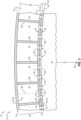
- FIGS. 1 and 2 are partial sectional illustrations of a structural, acoustic panel 20 for an acoustic system 22 (e.g., an active impedance control system) of an aircraft.
- This acoustic panel 20 may be configured to attenuate sound (e.g., noise) generated by a propulsion system of the aircraft.
- the aircraft propulsion system may be a turbofan propulsion system, a turbojet propulsion system, a turboprop propulsion system or any other ducted-rotor or open-rotor aircraft propulsion system.
- the acoustic panel 20 may be part of a housing (e.g., a nacelle) for an engine (e.g., a gas turbine engine) of the aircraft propulsion system.
- the acoustic panel 20 may be configured as or otherwise included as part of an inner barrel, an outer barrel, a translating sleeve, a blocker door, a bifurcation, etc.
- the acoustic panel 20 may be part of another component of the aircraft such as, but not limited to, an engine pylon, an aircraft wing or an aircraft fuselage.
- the acoustic panel 20 may also or alternatively be configured to attenuate aircraft related sound other than the sound generated by the aircraft propulsion system.
- the acoustic panel 20 may be described below as attenuating propulsion system sound and with respect to a component 24 (e.g., barrel) of the engine housing along a flowpath 26 (e.g., a bypass flowpath) within the aircraft propulsion system.
- a component 24 e.g., barrel
- a flowpath 26 e.g., a bypass flowpath
- the acoustic panel 20 extends axially along a centerline axis 28.
- this centerline axis 28 may be a centerline axis of the aircraft propulsion system, a centerline axis of the engine housing and/or a centerline axis of the component 24 (e.g., the barrel) which is formed by or otherwise includes the acoustic panel 20.
- the acoustic panel 20 extends radially between and to a radial inner side 30 of the acoustic panel 20 and a radial outer side 32 of the acoustic panel 20. Referring to FIG.
- the acoustic panel 20 extends circumferentially about (e.g., partially or completely around) the centerline axis 28.
- the component 24 and/or its acoustic panel 20 may thereby have a curved (e.g., arcuate, cylindrical, conical, frustoconical) geometry.
- the present disclosure is not limited to such an exemplary curved geometry.
- the acoustic panel 20 of FIGS. 1 and 2 includes a perforated face skin 34, a solid (e.g., non-perforated) back skin 36 and a cellular core 38.
- the face skin 34 is described below as an inner skin of the acoustic panel 20 and the back skin 36 is described below as an outer skin of the acoustic panel 20.
- the acoustic panel 20 and its face skin 34 may form an outer peripheral boundary of at least a portion of the flowpath 26 within the aircraft propulsion system.
- the face skin 34 may alternatively be the acoustic panel outer skin and the back skin 36 may alternatively be the acoustic panel inner skin.
- the acoustic panel 20 and its face skin 34 may form an inner peripheral boundary of at least a portion of the flowpath 26 within the aircraft propulsion system.
- the present disclosure is not limited to the foregoing exemplary arrangements.
- the acoustic panel 20, for example, may form a circumferential side boundary of the flowpath 26 and/or may otherwise be located with the aircraft propulsion system and/or the aircraft.
- the face skin 34 of FIGS. 1 and 2 extends axially along and circumferentially about the centerline axis 28.
- the face skin 34 has a radial thickness 40.
- This face skin thickness 40 extends radially between and to opposing sides 42 and 44 of the face skin 34, where the exterior side 42 of the face skin 34 is also the inner side 30 of the acoustic panel 20 of FIGS. 1 and 2 .
- the face skin thickness 40 may remain uniform (e.g., constant) as the face skin 34 extends axially along and/or circumferentially about the centerline axis 28.
- the face skin 34 of FIGS. 1 and 2 includes a face skin interior member 46, a face skin exterior member 48 and a plurality of face skin ports 50.
- the interior member 46 may be configured as an interior layer, an interior panel or another sheet-like body that forms an interior portion of the face skin 34.
- the interior member 46 of FIGS. 1 and 2 is formed by a relatively thin sheet or layer of material that extends axially along and circumferentially about the centerline axis 28.
- This interior member material may be or otherwise include a metal, a polymer (e.g., a thermoplastic or thermoset material) or a fiber reinforced composite (e.g., fiber reinforcement such as fiberglass, carbon fiber and/or aramid fibers within a polymer matrix).
- the interior member 46 has a radial thickness 52. This interior member thickness 52 extends radially between and to the face skin interior side 44 and an exterior side 54 of the interior member 46 at an interface between the interior member 46 and the exterior member 48.
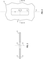
- the interior member 46 includes a plurality of interior member perforations 56 ("interior perforations"); e.g., through-holes such as slots or slits.
- interior perforations 56 extends generally radially through the interior member 46 along a centerline 58 of the respective interior perforation 56 from the interior member exterior side 54 to the face skin interior side 44.
- each interior perforation 56 may have an elongated cross-sectional geometry when viewed, for example, in a reference plane perpendicular to the interior perforation centerline 58.
- a minor axis 60 and a major axis 62 has a minor axis 60 and a major axis 62, where a major axis dimension of the interior perforation 56 along the major axis 62 is larger than a minor axis dimension of the interior perforation 56 along the minor axis 60.
- Example shapes of the elongated cross-sectional geometry include, but are not limited to, a polygon (e.g., a rectangle with rounded or sharp corners) and an oval.
- the major axis 62 is shown as being parallel with the centerline axis 28.
- the major axis 62 may alternatively be perpendicular to the centerline axis 28 or otherwise (e.g., non-zero acutely) angularly offset from the centerline axis 28 depending upon operation characteristics of the acoustic panel 20.
- the exterior member 48 may be configured as an exterior layer, an exterior panel or another sheet-like body that forms an exterior portion of the face skin 34.
- the exterior member 48 of FIGS. 1 and 2 is formed by a relatively thin sheet or layer of material that extends axially along and circumferentially about the centerline axis 28.
- This exterior member material may be or otherwise include a metal, a polymer (e.g., a thermoplastic or thermoset material) or a fiber reinforced composite (e.g., fiber reinforcement such as fiberglass, carbon fiber and/or aramid fibers within a polymer matrix).
- This exterior member material may be the same or different than the interior member material.
- the exterior member 48 has a radial thickness 64.
- This exterior member thickness 64 extends radially between and to the face skin exterior side 42 and an interior side 66 of the exterior member 48 at the interface between the interior member 46 and the exterior member 48.
- the exterior member thickness 64 of FIGS. 1 and 2 is equal to the interior member thickness 52. However, for select acoustic panel applications, the exterior member thickness 64 may alternatively be different (e.g., larger or smaller) than the interior member thickness 52.
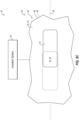
- the exterior member 48 includes a plurality of exterior member perforations 68 ("exterior perforations"); e.g., through-holes such as slots or slits.
- exterior perforations e.g., through-holes such as slots or slits.
- Each of these exterior perforations 68 extends generally radially through the exterior member 48 along a centerline 70 of the respective exterior perforation 68 from the exterior member interior side 66 to the face skin exterior side 42.
- each exterior perforation 68 may have an elongated cross-sectional geometry when viewed, for example, in a reference plane perpendicular to the exterior perforation centerline 70.
- a minor axis 72 and a major axis 74 where a major axis dimension of the exterior perforation 68 along the major axis 74 is larger than a minor axis dimension of the exterior perforation 68 along the minor axis 72.
- Example shapes of the elongated cross-sectional geometry include, but are not limited to, a polygon (e.g., a rectangle with rounded or sharp corners) and an oval.
- the major axis 74 is shown as being parallel with the centerline axis 28.
- the major axis 74 may alternatively be perpendicular to the centerline axis 28 or otherwise (e.g., non-zero acutely) angularly offset from the centerline axis 28 depending upon operation characteristics of the acoustic panel 20.
- the exterior perforation cross-sectional geometry and relative orientation of FIG. 6 is the same as the interior perforation cross-sectional geometry and relative orientation of FIG. 4 .
- the exterior perforation cross-sectional geometry may be different than (e.g., but, complimentary to) the interior perforation cross-sectional geometry.
- the interior member 46 and the exterior member 48 are arranged together to form the face skin 34.
- the interior member 46 may extend axially and circumferentially along (e.g., a portion or an entirety of) the exterior member 48.
- the exterior member 48 may extend axially and circumferentially along (e.g., a portion or an entirety of) the interior member 46.
- the face skin members 46 and 48 thereby configure at least a portion or an entirety of the face skin 34 as a multi-layered structure; e.g., a dual layered structure.
- the face skin members 46 and 48 are configured to move (e.g., slide, translate, etc.) relative to one another.
- Each of the face skin ports 50 extends generally radially through the face skin 34 from the face skin exterior side 42 to the face skin interior side 44.
- Each face skin port 50 of FIGS. 1 and 2 includes a respective one of the interior perforations 56 and a respective one of the exterior perforations 68. More particularly, each interior perforation 56 may extend radially through the interior member 46 from the face skin interior side 44 to the respective exterior perforation 68. Similarly, each exterior perforation 68 may extend radially through the exterior member 48 from the face skin exterior side 42 to the respective interior perforation 56.
- each interior perforation 56 is axially and circumferentially aligned with and fluidly coupled with a respective one of the exterior perforations 68 to form a respective one of the face skin ports 50 through the face skin 34.
- the specific alignment between the interior perforations 56 and the exterior perforations 68 may change during acoustic panel operation, engine operation or more generally aircraft operation.
- the back skin 36 of FIGS. 1 and 2 formed by a relatively thin sheet or layer of (e.g., continuous and uninterrupted) material that extends axially along and circumferentially about the centerline axis 28.
- This back skin material may be the same as or different than the interior member material and/or the exterior member material.
- the back skin material may be or otherwise include a metal, a polymer (e.g., a thermoplastic or thermoset material) or a fiber reinforced composite (e.g., fiber reinforcement such as fiberglass, carbon fiber and/or aramid fibers within a polymer matrix).
- the back skin 36 has a radial thickness 76.
- This back skin thickness 76 extends radially between opposing sides 78 and 80 of the back skin 36, where the exterior side 80 of the back skin 36 is also the outer side 32 of the acoustic panel 20 of FIGS. 1 and 2 .
- the back skin thickness 76 may remain uniform (e.g., constant) as the back skin 36 extends axially along and/or circumferentially about the centerline axis 28.
- the back skin thickness 76 of FIGS. 1 and 2 may be equal to the interior member thickness 52 and/or the exterior member thickness 64.
- the cellular core 38 is arranged and extends radially between the face skin 34 and the back skin 36.
- the cellular core 38 may also be connected to (a) the face skin 34 and its interior member 46 and/or (b) the back skin 36.
- the cellular core 38 for example, may be welded, brazed, fused, adhered and/or otherwise bonded to the interior member 46 and/or the back skin 36.
- the cellular core 38 of FIGS. 1 and 2 extends axially along and circumferentially about the centerline axis 28.
- the cellular core 38 has a radial depth 82. This cellular core depth 82 extends radially between and to the face skin 34 at its interior side 44 and the back skin 36 at its interior side 78.
- the cellular core depth 82 may remain uniform (e.g., constant) as the cellular core 38 extends axially along and/or circumferentially about the centerline axis 28.
- the cellular core depth 82 may be substantially larger than the face skin thickness 40 and/or the back skin thickness 76.
- the cellular core depth 82 for example, may be at least ten to forty times (10-40x), or more, larger than the face skin thickness 40 and/or the back skin thickness 76.
- the cellular core 38 of the present disclosure is not limited to such an exemplary dimensional relationship and may vary based on sound attenuation requirements, space requirements, etc.
- the cellular core 38 of FIGS. 1 and 2 is configured with one or more core chambers 84 (e.g., internal chambers, acoustic resonance chambers, internal cavities, etc.) radially between the face skin 34 and the back skin 36.
- the cellular core 38 may be configured as a honeycomb core.
- the cellular core 38 of FIG. 7 for example, includes a plurality of corrugated sidewalls 86.
- corrugated sidewalls 86 are arranged in a side-by-side array and are connected to one another such that each neighboring (e.g., adjacent) pair of the corrugated sidewalls 86 forms an array of the core chambers 84 laterally (e.g., circumferentially or axially) therebetween.
- the cellular core 38 and its corrugated sidewalls 86 may be constructed from or otherwise include a core material such as metal; e.g., sheet metal. The present disclosure, however, is not limited to such an exemplary cellular core construction nor material.
- Each core chamber 84 of FIGS. 1 and 2 extends radially within / through the cellular core 38 along a respective centerline 88 of the respective core chamber 84 between and to the face skin 34 at its face skin interior side 44 and the back skin 36 at its back skin interior side 78.
- One or more or all of the core chambers 84 may thereby each (e.g., axially and circumferentially) overlap and be fluidly coupled with a respective set of one or more of the face skin ports 50 and their respective interior perforations 56.
- each of the core chambers 84 has a cross-sectional geometry (e.g., shape, size, etc.) when viewed in a reference plane; e.g., a plane perpendicular to the chamber centerline 88 of the respective core chamber 84.
- This chamber cross-sectional geometry may have a polygonal shape (e.g., a hexagonal shape, a rectangular shape, a triangular shape, etc.) or a free form shape.
- the present disclosure is not limited to foregoing exemplary cellular core configuration.
- one or more or all of the core chambers 84 may alternatively each have a circular, elliptical or other non-polygonal cross-sectional geometry.
- various other types of honeycomb cores and, more generally, various other types of cellular cores for an acoustic panel are known in the art, and the present disclosure is not limited to any particular ones thereof.
- the acoustic panel 20 of FIGS. 1 and 2 is configured as a single-degree of freedom (SDOF) acoustic panel.
- SDOF single-degree of freedom
- One or more or all of the core chambers 84 of FIGS. 1 and 2 each extends radially uninterrupted between and to the face skin 34 and the back skin 36.
- the acoustic panel 20 may be tuned to attenuate, for example, a select frequency of sound, which tuning may be based on a radial height of each core chamber 84 / the cellular core depth 82.
- sound waves may enter a core chamber 84 through the respective face skin port(s) 50. These sound waves may travel through the core chamber 84 and reflect against the back skin 36. The reflected sound waves may travel back through the core chamber 84 and exit the acoustic panel 20 through the respective face skin port(s) 50, where those reflected sound waves may be out of phase from and destructively interfere with incoming soundwaves; i.e., pressure waves. Of course, the sound waves may also or alternatively reflect against one or more other elements of the acoustic panel 20 which may further influence sound attenuation.
- sound attenuation may be influenced by frictional losses in the face skin ports 50 (e.g., when pressure waves move in and out of the face skin ports 50 as the chambers 84 are energized and the acoustic panel 20 operates about its resonance frequency(ies)) thus converting the mechanical energy into heat dissipation.
- the propulsion system engine may operate at various different power settings. For example, during aircraft takeoff and/or climb, the propulsion system engine may operate at a relatively high power setting. During aircraft flyover, the propulsion system engine may operate at an intermediate (e.g., mid) power setting. During aircraft approach and/or landing, the propulsion system engine may operate at a relatively low power setting. Each of these engine power settings, as well as various power settings in between, may be associated with its own sound pressure level (SPL). For example, at the high power setting, the propulsion system engine and its propulsor rotor (e.g., a fan rotor) may generate a relatively high sound pressure level.
- SPL sound pressure level
- the propulsion system engine and its propulsor rotor may generate an intermediate sound pressure level.
- the propulsion system engine and its propulsor rotor may generate a relatively low sound pressure level.
- a flow resistance (R) along the acoustic panel 20 may non-linearly increase as the sound pressure level of the sound waves increases.
- the higher the flow resistance the less permeable a fluid such as air is through a porous material such as the face skin 34.
- optimum acoustic panel characteristics like acoustic flow resistance depend on the sound pressure level.
- Acoustic properties or characteristics of the acoustic panel 20 may therefore be changed (e.g., adapted, adjusted) to effectively respond to and attenuate a lower or higher sound pressure level.
- the acoustic properties / characteristics of the acoustic panel 20 may be changed to provide (or move closer to) an optimum flow resistance for each sound pressure level and flow (e.g., Mach number in the flowpath 26) operating condition.
- Parameters associated with the face skin ports 50 may affect the capability of the acoustic panel 20 to attenuate sound as well as aerodynamic characteristics of the acoustic panel 20.
- the acoustic panel 20 and, more particularly, the face skin 34 of FIGS. 8A-C have a percentage of open area (POA).
- POA percentage of open area
- the term "percentage of open area” may describe a percentage of a surface area of an element that is occupied by open area; e.g., voids from the face skin ports 50. This open area may be defined by a sum of flow areas 90 through the face skin 34.
- the term "flow area” may describe a minimum flow area (e.g., a throat) through a respective face skin port 50.
- This flow area 90 represents an area of (e.g., axial and circumferential) overlap between each exterior perforation 68 and a respective one of the interior perforations 56.
- the flow area 90 increases.
- the percentage of open area of the face skin 34 increases (e.g., see FIG. 8A )
- the face skin 34 becomes more permeable to a flow of fluid such as air.
- the overlap between the face skin perforations 56 and 68 decreases (e.g., see FIG. 8C )
- the flow area 90 decreases.
- the percentage of open area of the face skin 34 decreases (e.g., see FIG.
- the face skin 34 becomes less permeable to the flow of fluid.
- the face skin members 46 and 48 may thereby be arranged relative to one another to provide a select (e.g., optimum, enhanced, etc.) complex acoustic impendence (Z) value for the high, the intermediate and the low power settings as well as various power settings in-between.
- the face skin members 46 and 48 may be arranged at a first position (e.g., a fully open and/or maximum POA position) as shown in FIG. 8A .
- the face skin 34 may have a relatively high percentage of open area; e.g., 90-100% of maximum POA for the acoustic panel 20.
- a relatively high percentage e.g., 90-100%) of each exterior perforation 68 may overlap a respective one of the interior perforations 56.
- each interior perforation 56 may also or alternatively overlap a respective one of the exterior perforations 68.
- the flow area 90 through each face skin port 50 may thereby be sized to optimize the complex acoustic impendence (Z) value for the high sound pressure level associated with high power setting operation.
- Z complex acoustic impendence
- the face skin members 46 and 48 may be arranged at a second position (e.g., intermediate position) as shown in FIG. 8B .
- the face skin 34 may have an intermediate percentage of open area; e.g., 80-90% of maximum POA for the acoustic panel 20.
- an intermediate percentage e.g., 80-90%) of each exterior perforation 68 may overlap a respective one of the interior perforations 56.
- an intermediate percentage (e.g., 80-90%) of each interior perforation 56 may also or alternatively overlap a respective one of the exterior perforations 68.
- the flow area 90 through each face skin port 50 may thereby be sized to optimize the complex acoustic impendence (Z) value for the intermediate sound pressure level associated with intermediate power setting operation.
- Z complex acoustic impendence
- the present disclosure is not limited to the foregoing exemplary overlap percentages as these percentages may vary based on perforation size, shape as well as other engine operating parameters.
- the face skin members 46 and 48 may be arranged at a third position (e.g., a fully restricted and/or minimum PA position) as shown in FIG. 8C .
- the face skin 34 may have a relatively low percentage of open area; e.g., 50-70% of maximum POA for the acoustic panel 20.
- a relatively low percentage e.g., 50-70%) of each exterior perforation 68 may overlap a respective one of the interior perforations 56.
- each interior perforation 56 may also or alternatively overlap a respective one of the exterior perforations 68.
- the flow area 90 through each face skin port 50 may thereby be sized to optimize the complex acoustic impendence (Z) value for the low sound pressure level associated with low power setting operation.
- Z complex acoustic impendence
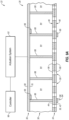
- the acoustic panel 20 of FIGS. 8A-C is configured with an actuation system 92.
- This actuation system 92 is operatively coupled to the face skin 34 and one of its face skin members 46, 48 - an actuatable face skin member.
- the actuation system 92 may be (e.g., directly or indirectly) connected to the interior member 46; here, the actuatable face skin member.
- the exterior member 48 may be grounded (e.g., fixed) to another stationary support or frame of the aircraft.
- the actuation system 92 may thereby move (e.g., slide, translate, etc.) the interior member 46 (and elements 36 and 38) along the exterior member 48.
- the actuation system 92 may be (e.g., directly or indirectly) connected to the exterior member 48; here, the actuatable face skin member.
- the interior member 46 (and elements 36 and 38) may be grounded (e.g., fixed) to another stationary support or frame of the aircraft.
- the actuation system 92 may thereby move (e.g., slide, translate, etc.) the exterior member 48 along the interior member 46.
- the movement of the actuatable face skin member 46, 48 is shown in FIGS. 8A-C as axial movement along the centerline axis 28.
- the movement may alternatively be circumferential movement about the centerline axis 28.
- the movement may include both an axial and circumferential component; e.g., the actuatable face skin member 46, 48 may spiral along and about the centerline axis 28.
- the acoustic system 22 of FIGS. 9A and 9B may also include a sensor system 94.
- This sensor system 94 is configured to monitor (e.g., measure or otherwise determine) one or more acoustic parameters at the acoustic panel 20 and its face skin 34 using sensors 96.
- the acoustic parameters include, but are not limited to, a sound pressure level at the face skin 34 and an acoustic impendence at the face skin 34 and at the back skin 36.
- Examples of the sensors 96 include, but are not limited to, microphones, pressure transducers, and pressure probes.
- the sensor system 94 of FIGS. 9A and 9B is also configured to provide (e.g., generate and output) a sensor signal indicative of the one or more acoustic parameters, for example, from each sensor 96. Based on these sensor signals, the actuation system 92 may move the actuatable face skin member 46, 48.
- a controller 98 (incorporated into or discrete from the actuation system 92) may receive the sensor signals and process the sensor signals to provide a control signal. More particularly, the controller 98 is programmed to process the sensor signals to educe a measured impedance.
- the controller 98 may compare the measured impedance (Z meas ) to an optimum impedance (Z opt ) to generate the control signal, which control signal may be in the form of an output signal or power from the controller 98 to drive the actuation system 92.
- This control signal may be proportional to intended adjustment to the percentage of open area to the fan skin 34.
- the actuation system 92 may move the actuatable face skin member 46, 48 in response to the control signal. With this operability, the actuatable face skin member 46, 48 may be moved to provide a select (e.g., optimal) percentage of open area / a select (e.g., optimal) acoustic impedance for the sound pressure level measured at the acoustic panel 20.
- the control signal may also be generated based on another acoustic parameter such as the acoustic impedance at the acoustic panel 20.
- the controller 98 may utilize feedback to determine if the predicted acoustic impedance is equal to or close to the measured acoustic impedance.
- the acoustic system 22 may thereby provide tuned (e.g., optimized) acoustic attenuation across various different operating conditions / phases of aircraft flight.
- a typical prior art acoustic panel is tuned for a specific operating condition / phase of flight, and settles for sub-optimal operation at other operating conditions / phases of flight.
- the controller 98 may process the sensor signal using models and/or look-up tables. The controller 98 may thereby provide the control signal based on the sensor signal (e.g., measurements) as well as operating conditions of the propulsion system engine. Examples of the engine operating conditions include, but are not limited to, the engine power setting, a rotational speed of an engine rotor, a speed of the aircraft, and a temperature of ambient air.
- the acoustic panel 20 is described above as a single-degree of freedom acoustic panel for ease of description.
- the present disclosure is not limited to such an exemplary acoustic panel configuration.
- the acoustic panel 20 may alternatively be configured as a multi-degree of freedom (MDOF) acoustic panel such as, but not limited to, a double-degree of freedom (DDOF) acoustic panel.
- MDOF multi-degree of freedom
- DDOF double-degree of freedom
- One or more or all of the core chambers 84 of FIG. 10 is provided with at least (or only) one respective septum 100; e.g., a perforated and/or porous member.
- Each septum 100 extends laterally across the respective core chamber 84 to divide that core chamber 84 into a plurality of sub-chambers 84A and 84B. These sub-chambers 84A and 84B are fluidly coupled with one another (e.g., radially) across the respective septum 100 through one or more perforations 102 (or pores) in that septum 100.
- the acoustic panel 20 may be tuned to attenuate multiple frequencies of sound or to widen a frequency band of attenuation, which tuning may be based on the radial height of each core chamber 84 / the cellular core depth 82, a radial distance between each septum 100 and the face skin 34 as well as the flow resistance (R) for each layer.
- sound waves may enter a core chamber 84 through the respective face skin port(s) 50. Some of these sound waves may travel through the near sub-chamber 84A and reflect against solid portion(s) of the septum 100. The reflected sound waves may travel back through the near sub-chamber 84A and exit the acoustic panel 20 through the respective face skin port(s) 50, where those reflected sound waves may be out of phase from and destructively interfere with incoming soundwaves of a first frequency. Other sound waves may pass through porous portion(s) of the septum 100 and travel through the far sub-chamber 84B and reflect against the back skin 36.
- the reflected sound waves may travel back through the far sub-chamber 84B, across the septum 100, through the near sub-chamber 84A and exit the acoustic panel 20 through the respective face skin port(s) 50, where those reflected sound waves may be out of phase from and destructively interfere with other incoming soundwaves of a second frequency.
- the sound waves may also or alternatively reflect against one or more other elements of the acoustic panel 20 which may further influence sound attenuation.
- FIG. 11 illustrates an example of the aircraft propulsion system with which the one or more of the acoustic panels 20 may be configured.
- This aircraft propulsion system includes a turbofan gas turbine engine 104.
- the gas turbine engine 104 of FIG. 11 extends axially along the centerline axis 28 between an upstream airflow inlet 106 and a downstream airflow exhaust 108.
- the gas turbine engine 104 includes a fan section 110, a compressor section 111, a combustor section 112 and a turbine section 113.
- the turbine section 113 includes a high pressure turbine (HPT) section 113A and a low pressure turbine (LPT) section 113B, which LPT section 113B may also be referred to as a power turbine (PT) section.
- HPT high pressure turbine
- LPT low pressure turbine
- the engine sections 110-113B are arranged within the engine housing 116.
- This engine housing 116 includes an inner housing structure 118 and an outer housing structure 120.
- the inner housing structure 118 may house one or more of the engine sections 111-113B; e.g., a core of the gas turbine engine 104.
- the outer housing structure 120 may house at least the fan section 110.
- the inner and the outer housing structures 118 and 20 of FIG. 11 also form a bypass duct.
- the inner and/or the outer housing structure 120 may each include one or more of the acoustic panels 20.
- Each of the engine sections 110, 111, 113A and 113B includes a respective bladed rotor 122-125.
- Each of these bladed rotors 122-125 includes a plurality of rotor blades arranged circumferentially around and connected to one or more respective rotor disks.
- the rotor blades may be formed integral with or mechanically fastened, welded, brazed, adhered and/or otherwise attached to the respective rotor disk(s).
- the fan rotor 122 is connected to and driven by the LPT rotor 125 through a low speed shaft 128.
- the compressor rotor 123 is connected to and driven by the HPT rotor 124 through a high speed shaft 130.
- the shafts 128 and 130 are rotatably supported by a plurality of bearings (not shown). Each of these bearings is connected to the engine housing 116 by at least one stationary structure.
- This air is directed through the fan section 110 and into a core flowpath 132 and a bypass flowpath 134 (e.g., the flowpath 26).
- the core flowpath 132 extends sequentially through the engine sections 111-113B.
- the air within the core flowpath 132 may be referred to as "core air”.
- the bypass flowpath 134 extends through the bypass duct, which bypasses the engine core.
- the air within the bypass flowpath 134 may be referred to as "bypass air”.
- the core air is compressed by the compressor rotor 123 and directed into a combustion chamber 136 of a combustor 138 in the combustor section 112. Fuel is injected into the combustion chamber 136 and mixed with the compressed core air to provide a fuel-air mixture. This fuel air mixture is ignited and combustion products thereof flow through and sequentially cause the HPT rotor 124 and the LPT rotor 125 to rotate.
- the rotation of the HPT rotor 124 drives rotation of the compressor rotor 123 and, thus, compression of the air received from a core airflow inlet.
- the rotation of the LPT rotor 125 drives rotation of the fan rotor 122, which propels the bypass air through and out of the bypass flowpath 134.
- the propulsion of the bypass air may account for a majority of thrust generated by the gas turbine engine 104.
- the acoustic system 22 and its acoustic panel 20 may be included in various gas turbine engines other than the one described above.
- the acoustic system 22 and its acoustic panel 20, for example, may be included in a geared gas turbine engine where a geartrain connects one or more shafts to one or more rotors in a fan section, a compressor section and/or any other engine section.
- the acoustic system 22 and its acoustic panel 20 may be included in a gas turbine engine configured without a geartrain; e.g., a direct drive gas turbine engine.
- the acoustic system 22 and its acoustic panel 20 may be included in a gas turbine engine configured with a single spool, with two spools (e.g., see FIG. 11 ), or with more than two spools.
- the gas turbine engine may be configured as a turbofan engine, a turbojet engine, a turboprop engine, a turboshaft engine, a propfan engine, a pusher fan engine or any other type of gas turbine engine.
- the gas turbine engine may alternatively be configured as an auxiliary power unit (APU).
- APU auxiliary power unit
- the present disclosure therefore is not limited to any particular types or configurations of gas turbine engines.
- the acoustic system 22 and its acoustic panel 20 is described above with respect to various aircraft applications, the acoustic system 22 and its acoustic panel 20 of the present application may alternatively be used for non-aircraft applications.
Landscapes
- Engineering & Computer Science (AREA)
- Chemical & Material Sciences (AREA)
- Combustion & Propulsion (AREA)
- Mechanical Engineering (AREA)
- General Engineering & Computer Science (AREA)
- Aviation & Aerospace Engineering (AREA)
- Physics & Mathematics (AREA)
- Acoustics & Sound (AREA)
- Multimedia (AREA)
- Soundproofing, Sound Blocking, And Sound Damping (AREA)
Abstract
Description
- This disclosure relates generally to an acoustic panel for, for example, an aircraft propulsion system.
- An aircraft propulsion system may include one or more acoustic panels for attenuating sound generated by its gas turbine engine. Various types and configurations of acoustic panels are known in the art. While these known acoustic panels have various benefits, there is still room in the art for improvement.
- According to an aspect of the present invention, an acoustic system is provided that includes a face skin, a back skin and a cellular core arranged between the face skin and the back skin. The face skin includes a first member, a second member and a plurality of ports extending through the face skin. The first member includes a plurality of first perforations. The second member includes a plurality of second perforations and is configured to move along the first member. Each of the ports includes a respective one of the first perforations and a respective one of the second perforations. The cellular core includes a plurality of chambers. Each of the chambers extends between the face skin and the back skin. Each of the chambers is fluidly coupled with a respective one or more of the ports.
- According to another aspect of the present invention, another acoustic system is provided that includes an acoustic panel and an actuation system. The acoustic panel includes a face skin, a back skin and a cellular core connected to the face skin and the back skin. The face skin includes a plurality of ports extending through the face skin. The face skin has an acoustic impedance. The cellular core includes a plurality of chambers. Each of the chambers extends from the face skin to the back skin. Each of the chambers is fluidly coupled with a respective one or more of the ports. The actuation system is operatively coupled with the acoustic panel. The actuation system is configured to manipulate the face skin to change the acoustic impedance during operation of the acoustic system.
- According to another aspect of the present invention, a method is provided for sound attenuation. During this method, an acoustic parameter is monitored at an acoustic panel. A sensor signal is provided indicative of the acoustic parameter. The acoustic panel includes a face skin, a back skin and a cellular core connected to the face skin and the back skin. The face skin includes a plurality of ports extending through the face skin. The cellular core includes a plurality of chambers. Each of the chambers extends from the face skin to the back skin. Each of the chambers is fluidly coupled with a respective one or more of the ports. The face skin is manipulated to change an acoustic impedance of the face skin based on the sensor signal.
- The following optional features may be applied individually, or in any combination, to any of the above aspects of the invention:
In an embodiment of the above, the actuation system may be configured to manipulate the face skin to change a flow area of one or more of the ports. - In another embodiment according to any of the previous embodiments, the face skin may include an exterior member and an interior member between the exterior member and the cellular core. The actuation system may be configured to move one of the exterior member or the interior member along another one of the exterior member or the interior member to change the acoustic impedance.
- In another embodiment according to any of the previous embodiments, the acoustic system may also include a sensor system configured to monitor an acoustic parameter and provide a sensor signal indicative of the acoustic parameter. The actuation system may be configured to manipulate the face skin based on the sensor signal.
- In another embodiment according to any of the previous embodiments, the second member may be configured to move along the first member to change an acoustic impedance of the face skin.
- In another embodiment according to any of the previous embodiments, the second member may be configured to move along the first member to change a flow area through each of the plurality of ports.
- In another embodiment according to any of the previous embodiments, a first of the ports may include a first of the first perforations and a first of the second perforations. The second member may be configured to move along the first member between a first position and a second position. The first of the second perforations may overlap the first of the first perforations a first percentage when the second member is in the first position. The first of the second perforations may overlap the first of the first perforations a second percentage when the second member is in the second position. The second percentage may be different than the first percentage.
- In another embodiment according to any of the previous embodiments, a first of the ports may include a first of the first perforations and a first of the second perforations. The first of the first perforations may have an elongated cross-sectional geometry. The first of the second perforations may have an elongated cross-sectional geometry.
- In another embodiment according to any of the previous embodiments, the second member may be configured to move along the first member in a first direction. A major axis of the first of the first perforations and a major axis of the first of the second perforations may be parallel with the first direction.
- In another embodiment according to any of the previous embodiments, the first member may be an exterior member of the face skin. The second member may be an interior member of the face skin. The interior member may be disposed between the exterior member and the cellular core.
- In another embodiment according to any of the previous embodiments, the cellular core may be connected to the second member and the back skin.
- In another embodiment according to any of the previous embodiments, the first member may be an interior member of the face skin. The second member may be an exterior member of the face skin. The interior member may be disposed between the exterior member and the cellular core.
- In another embodiment according to any of the previous embodiments, the cellular core may be connected to the first member and the back skin.
- In another embodiment according to any of the previous embodiments, the acoustic system may also include an acoustic panel including the face skin, the back skin and the cellular core. The acoustic panel may extend axially along and circumferentially about a centerline. The second member may be configured to move in an axial direction along the first member.
- In another embodiment according to any of the previous embodiments, the acoustic system may also include an acoustic panel including the face skin, the back skin and the cellular core. The acoustic panel may extend axially along and circumferentially about a centerline. The second member may be configured to move in a circumferential direction along the first member.
- In another embodiment according to any of the previous embodiments, the acoustic system may also include an actuation system configured to move the second member along the first member.
- In another embodiment according to any of the previous embodiments, the acoustic system may also include a sensor system configured to monitor an acoustic parameter and provide a sensor signal indicative of the acoustic parameter. The actuation system may be configured to move the second member along the first member based on the sensor signal.
- In another embodiment according to any of the previous embodiments, a first of the chambers may extend un-interrupted through the cellular core from the face skin to the back skin.
- In another embodiment according to any of the previous embodiments, the cellular core may include a septum dividing a first of the chambers into a plurality of fluidly coupled sub-chambers.
- In another embodiment according to any of the previous embodiments, the acoustic system may also include a component of an aircraft propulsion system. The component may include the face skin, the back skin and the cellular core.
- The present disclosure may include any one or more of the individual features disclosed above and/or below alone or in any combination thereof.
- The foregoing features and the operation of the invention will become more apparent in light of the following description and the accompanying drawings.
-
-
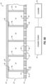
FIG. 1 is a partial side sectional illustration of an acoustic panel for an acoustic system. -
FIG. 2 is a partial cross-sectional illustration of the acoustic panel. -
FIG. 3 is a partial side sectional illustration of an interior member of a face skin for the acoustic panel taken along line 3-3 inFIG. 4 . -
FIG. 4 is a partial illustration of the interior member of the face skin. -
FIG. 5 is a partial side sectional illustration of an exterior member of the face skin taken along line 5-5 inFIG. 6 . -
FIG. 6 is a partial illustration of the exterior member of the face skin. -
FIG. 7 is a partial perspective cutaway illustration of the acoustic panel. -
FIGS. 8A-C are partial schematic illustrations of the acoustic system with the members of the face skin in various arrangements. -
FIGS. 9A and9B are partial schematic sectional illustrations of the acoustic system with an actuation system coupled to and configured to move different members of the face skin. -
FIG. 10 is a partial side sectional illustration of the acoustic panel configured as a multi-degree of freedom acoustic panel. -
FIG. 11 is a schematic side sectional illustration of an aircraft propulsion system configured with one or more of the acoustic panels. -
FIGS. 1 and2 are partial sectional illustrations of a structural,acoustic panel 20 for an acoustic system 22 (e.g., an active impedance control system) of an aircraft. Thisacoustic panel 20 may be configured to attenuate sound (e.g., noise) generated by a propulsion system of the aircraft. The aircraft propulsion system may be a turbofan propulsion system, a turbojet propulsion system, a turboprop propulsion system or any other ducted-rotor or open-rotor aircraft propulsion system. Theacoustic panel 20 may be part of a housing (e.g., a nacelle) for an engine (e.g., a gas turbine engine) of the aircraft propulsion system. Theacoustic panel 20, for example, may be configured as or otherwise included as part of an inner barrel, an outer barrel, a translating sleeve, a blocker door, a bifurcation, etc. Alternatively, theacoustic panel 20 may be part of another component of the aircraft such as, but not limited to, an engine pylon, an aircraft wing or an aircraft fuselage. Furthermore, theacoustic panel 20 may also or alternatively be configured to attenuate aircraft related sound other than the sound generated by the aircraft propulsion system. However, for ease of description, theacoustic panel 20 may be described below as attenuating propulsion system sound and with respect to a component 24 (e.g., barrel) of the engine housing along a flowpath 26 (e.g., a bypass flowpath) within the aircraft propulsion system. - Referring to
FIG. 1 , theacoustic panel 20 extends axially along acenterline axis 28. Briefly, thiscenterline axis 28 may be a centerline axis of the aircraft propulsion system, a centerline axis of the engine housing and/or a centerline axis of the component 24 (e.g., the barrel) which is formed by or otherwise includes theacoustic panel 20. Theacoustic panel 20 extends radially between and to a radial inner side 30 of theacoustic panel 20 and a radial outer side 32 of theacoustic panel 20. Referring toFIG. 2 , theacoustic panel 20 extends circumferentially about (e.g., partially or completely around) thecenterline axis 28. The component 24 and/or itsacoustic panel 20 may thereby have a curved (e.g., arcuate, cylindrical, conical, frustoconical) geometry. The present disclosure, however, is not limited to such an exemplary curved geometry. - The
acoustic panel 20 ofFIGS. 1 and2 includes aperforated face skin 34, a solid (e.g., non-perforated) backskin 36 and acellular core 38. For ease of description, theface skin 34 is described below as an inner skin of theacoustic panel 20 and theback skin 36 is described below as an outer skin of theacoustic panel 20. With such an arrangement, theacoustic panel 20 and itsface skin 34 may form an outer peripheral boundary of at least a portion of theflowpath 26 within the aircraft propulsion system. It is contemplated, however, theface skin 34 may alternatively be the acoustic panel outer skin and theback skin 36 may alternatively be the acoustic panel inner skin. With such an arrangement, theacoustic panel 20 and itsface skin 34 may form an inner peripheral boundary of at least a portion of theflowpath 26 within the aircraft propulsion system. The present disclosure, of course, is not limited to the foregoing exemplary arrangements. Theacoustic panel 20, for example, may form a circumferential side boundary of theflowpath 26 and/or may otherwise be located with the aircraft propulsion system and/or the aircraft. - The
face skin 34 ofFIGS. 1 and2 extends axially along and circumferentially about thecenterline axis 28. Theface skin 34 has aradial thickness 40. Thisface skin thickness 40 extends radially between and to opposingsides 42 and 44 of theface skin 34, where the exterior side 42 of theface skin 34 is also the inner side 30 of theacoustic panel 20 ofFIGS. 1 and2 . Theface skin thickness 40 may remain uniform (e.g., constant) as theface skin 34 extends axially along and/or circumferentially about thecenterline axis 28. Theface skin 34 ofFIGS. 1 and2 includes a faceskin interior member 46, a faceskin exterior member 48 and a plurality offace skin ports 50. - The
interior member 46 may be configured as an interior layer, an interior panel or another sheet-like body that forms an interior portion of theface skin 34. Theinterior member 46 ofFIGS. 1 and2 , for example, is formed by a relatively thin sheet or layer of material that extends axially along and circumferentially about thecenterline axis 28. This interior member material may be or otherwise include a metal, a polymer (e.g., a thermoplastic or thermoset material) or a fiber reinforced composite (e.g., fiber reinforcement such as fiberglass, carbon fiber and/or aramid fibers within a polymer matrix). Theinterior member 46 has aradial thickness 52. Thisinterior member thickness 52 extends radially between and to the face skininterior side 44 and anexterior side 54 of theinterior member 46 at an interface between theinterior member 46 and theexterior member 48. - Referring to
FIG. 3 , theinterior member 46 includes a plurality of interior member perforations 56 ("interior perforations"); e.g., through-holes such as slots or slits. Each of theseinterior perforations 56 extends generally radially through theinterior member 46 along acenterline 58 of the respectiveinterior perforation 56 from the interiormember exterior side 54 to the face skininterior side 44. Referring toFIG. 4 , eachinterior perforation 56 may have an elongated cross-sectional geometry when viewed, for example, in a reference plane perpendicular to theinterior perforation centerline 58. Theinterior perforation 56 ofFIG. 4 , for example, has aminor axis 60 and amajor axis 62, where a major axis dimension of theinterior perforation 56 along themajor axis 62 is larger than a minor axis dimension of theinterior perforation 56 along theminor axis 60. Example shapes of the elongated cross-sectional geometry include, but are not limited to, a polygon (e.g., a rectangle with rounded or sharp corners) and an oval. For ease of description, themajor axis 62 is shown as being parallel with thecenterline axis 28. It is contemplated, however, themajor axis 62 may alternatively be perpendicular to thecenterline axis 28 or otherwise (e.g., non-zero acutely) angularly offset from thecenterline axis 28 depending upon operation characteristics of theacoustic panel 20. - Referring to
FIGS. 1 and2 , theexterior member 48 may be configured as an exterior layer, an exterior panel or another sheet-like body that forms an exterior portion of theface skin 34. Theexterior member 48 ofFIGS. 1 and2 , for example, is formed by a relatively thin sheet or layer of material that extends axially along and circumferentially about thecenterline axis 28. This exterior member material may be or otherwise include a metal, a polymer (e.g., a thermoplastic or thermoset material) or a fiber reinforced composite (e.g., fiber reinforcement such as fiberglass, carbon fiber and/or aramid fibers within a polymer matrix). This exterior member material may be the same or different than the interior member material. Theexterior member 48 has aradial thickness 64. Thisexterior member thickness 64 extends radially between and to the face skin exterior side 42 and aninterior side 66 of theexterior member 48 at the interface between theinterior member 46 and theexterior member 48. Theexterior member thickness 64 ofFIGS. 1 and2 is equal to theinterior member thickness 52. However, for select acoustic panel applications, theexterior member thickness 64 may alternatively be different (e.g., larger or smaller) than theinterior member thickness 52. - Referring to
FIG. 5 , theexterior member 48 includes a plurality of exterior member perforations 68 ("exterior perforations"); e.g., through-holes such as slots or slits. Each of theseexterior perforations 68 extends generally radially through theexterior member 48 along acenterline 70 of therespective exterior perforation 68 from the exterior memberinterior side 66 to the face skin exterior side 42. Referring toFIG. 6 , eachexterior perforation 68 may have an elongated cross-sectional geometry when viewed, for example, in a reference plane perpendicular to theexterior perforation centerline 70. Theexterior perforation 68 ofFIG. 6 , for example, has aminor axis 72 and amajor axis 74, where a major axis dimension of theexterior perforation 68 along themajor axis 74 is larger than a minor axis dimension of theexterior perforation 68 along theminor axis 72. Example shapes of the elongated cross-sectional geometry include, but are not limited to, a polygon (e.g., a rectangle with rounded or sharp corners) and an oval. For ease of description, themajor axis 74 is shown as being parallel with thecenterline axis 28. It is contemplated, however, themajor axis 74 may alternatively be perpendicular to thecenterline axis 28 or otherwise (e.g., non-zero acutely) angularly offset from thecenterline axis 28 depending upon operation characteristics of theacoustic panel 20. In general, the exterior perforation cross-sectional geometry and relative orientation ofFIG. 6 is the same as the interior perforation cross-sectional geometry and relative orientation ofFIG. 4 . However, for select acoustic panel applications, the exterior perforation cross-sectional geometry may be different than (e.g., but, complimentary to) the interior perforation cross-sectional geometry. - Referring to
FIGS. 1 and2 , theinterior member 46 and theexterior member 48 are arranged together to form theface skin 34. Theinterior member 46 may extend axially and circumferentially along (e.g., a portion or an entirety of) theexterior member 48. Theexterior member 48 may extend axially and circumferentially along (e.g., a portion or an entirety of) theinterior member 46. Theface skin members face skin 34 as a multi-layered structure; e.g., a dual layered structure. However, as discussed below in further detail, theface skin members - Each of the
face skin ports 50 extends generally radially through theface skin 34 from the face skin exterior side 42 to the face skininterior side 44. Eachface skin port 50 ofFIGS. 1 and2 , for example, includes a respective one of theinterior perforations 56 and a respective one of theexterior perforations 68. More particularly, eachinterior perforation 56 may extend radially through theinterior member 46 from the face skininterior side 44 to therespective exterior perforation 68. Similarly, eachexterior perforation 68 may extend radially through theexterior member 48 from the face skin exterior side 42 to the respectiveinterior perforation 56. Thus, eachinterior perforation 56 is axially and circumferentially aligned with and fluidly coupled with a respective one of theexterior perforations 68 to form a respective one of theface skin ports 50 through theface skin 34. Note, as discussed below in further detail, the specific alignment between theinterior perforations 56 and theexterior perforations 68 may change during acoustic panel operation, engine operation or more generally aircraft operation. - The
back skin 36 ofFIGS. 1 and2 formed by a relatively thin sheet or layer of (e.g., continuous and uninterrupted) material that extends axially along and circumferentially about thecenterline axis 28. This back skin material may be the same as or different than the interior member material and/or the exterior member material. The back skin material, for example, may be or otherwise include a metal, a polymer (e.g., a thermoplastic or thermoset material) or a fiber reinforced composite (e.g., fiber reinforcement such as fiberglass, carbon fiber and/or aramid fibers within a polymer matrix). Theback skin 36 has aradial thickness 76. Thisback skin thickness 76 extends radially between opposingsides back skin 36, where theexterior side 80 of theback skin 36 is also the outer side 32 of theacoustic panel 20 ofFIGS. 1 and2 . Theback skin thickness 76 may remain uniform (e.g., constant) as theback skin 36 extends axially along and/or circumferentially about thecenterline axis 28. Theback skin thickness 76 ofFIGS. 1 and2 may be equal to theinterior member thickness 52 and/or theexterior member thickness 64. - The
cellular core 38 is arranged and extends radially between theface skin 34 and theback skin 36. Thecellular core 38 may also be connected to (a) theface skin 34 and itsinterior member 46 and/or (b) theback skin 36. Thecellular core 38, for example, may be welded, brazed, fused, adhered and/or otherwise bonded to theinterior member 46 and/or theback skin 36. Thecellular core 38 ofFIGS. 1 and2 extends axially along and circumferentially about thecenterline axis 28. Thecellular core 38 has aradial depth 82. Thiscellular core depth 82 extends radially between and to theface skin 34 at itsinterior side 44 and theback skin 36 at itsinterior side 78. Thecellular core depth 82 may remain uniform (e.g., constant) as thecellular core 38 extends axially along and/or circumferentially about thecenterline axis 28. Thecellular core depth 82 may be substantially larger than theface skin thickness 40 and/or theback skin thickness 76. Thecellular core depth 82, for example, may be at least ten to forty times (10-40x), or more, larger than theface skin thickness 40 and/or theback skin thickness 76. Thecellular core 38 of the present disclosure, however, is not limited to such an exemplary dimensional relationship and may vary based on sound attenuation requirements, space requirements, etc. - The
cellular core 38 ofFIGS. 1 and2 is configured with one or more core chambers 84 (e.g., internal chambers, acoustic resonance chambers, internal cavities, etc.) radially between theface skin 34 and theback skin 36. Referring toFIG. 7 , thecellular core 38 may be configured as a honeycomb core. Thecellular core 38 ofFIG. 7 , for example, includes a plurality ofcorrugated sidewalls 86. These corrugated sidewalls 86 are arranged in a side-by-side array and are connected to one another such that each neighboring (e.g., adjacent) pair of the corrugated sidewalls 86 forms an array of thecore chambers 84 laterally (e.g., circumferentially or axially) therebetween. Thecellular core 38 and itscorrugated sidewalls 86 may be constructed from or otherwise include a core material such as metal; e.g., sheet metal. The present disclosure, however, is not limited to such an exemplary cellular core construction nor material. - Each
core chamber 84 ofFIGS. 1 and2 extends radially within / through thecellular core 38 along arespective centerline 88 of therespective core chamber 84 between and to theface skin 34 at its face skininterior side 44 and theback skin 36 at its back skininterior side 78. One or more or all of thecore chambers 84 may thereby each (e.g., axially and circumferentially) overlap and be fluidly coupled with a respective set of one or more of theface skin ports 50 and their respectiveinterior perforations 56. Referring toFIG. 7 , each of thecore chambers 84 has a cross-sectional geometry (e.g., shape, size, etc.) when viewed in a reference plane; e.g., a plane perpendicular to thechamber centerline 88 of therespective core chamber 84. This chamber cross-sectional geometry may have a polygonal shape (e.g., a hexagonal shape, a rectangular shape, a triangular shape, etc.) or a free form shape. The present disclosure, however, is not limited to foregoing exemplary cellular core configuration. For example, one or more or all of thecore chambers 84 may alternatively each have a circular, elliptical or other non-polygonal cross-sectional geometry. Furthermore, various other types of honeycomb cores and, more generally, various other types of cellular cores for an acoustic panel are known in the art, and the present disclosure is not limited to any particular ones thereof. - The
acoustic panel 20 ofFIGS. 1 and2 is configured as a single-degree of freedom (SDOF) acoustic panel. One or more or all of thecore chambers 84 ofFIGS. 1 and2 , for example, each extends radially uninterrupted between and to theface skin 34 and theback skin 36. With such an arrangement, theacoustic panel 20 may be tuned to attenuate, for example, a select frequency of sound, which tuning may be based on a radial height of eachcore chamber 84 / thecellular core depth 82. - During operation of the
acoustic panel 20 ofFIGS. 1 and2 , sound waves may enter acore chamber 84 through the respective face skin port(s) 50. These sound waves may travel through thecore chamber 84 and reflect against theback skin 36. The reflected sound waves may travel back through thecore chamber 84 and exit theacoustic panel 20 through the respective face skin port(s) 50, where those reflected sound waves may be out of phase from and destructively interfere with incoming soundwaves; i.e., pressure waves. Of course, the sound waves may also or alternatively reflect against one or more other elements of theacoustic panel 20 which may further influence sound attenuation. Moreover, sound attenuation may be influenced by frictional losses in the face skin ports 50 (e.g., when pressure waves move in and out of theface skin ports 50 as thechambers 84 are energized and theacoustic panel 20 operates about its resonance frequency(ies)) thus converting the mechanical energy into heat dissipation. - During an aircraft flight, the propulsion system engine may operate at various different power settings. For example, during aircraft takeoff and/or climb, the propulsion system engine may operate at a relatively high power setting. During aircraft flyover, the propulsion system engine may operate at an intermediate (e.g., mid) power setting. During aircraft approach and/or landing, the propulsion system engine may operate at a relatively low power setting. Each of these engine power settings, as well as various power settings in between, may be associated with its own sound pressure level (SPL). For example, at the high power setting, the propulsion system engine and its propulsor rotor (e.g., a fan rotor) may generate a relatively high sound pressure level. At the intermediate power setting, the propulsion system engine and its propulsor rotor (e.g., a fan rotor) may generate an intermediate sound pressure level. At the low power setting, the propulsion system engine and its propulsor rotor (e.g., a fan rotor) may generate a relatively low sound pressure level.
- A flow resistance (R) along the
acoustic panel 20 may non-linearly increase as the sound pressure level of the sound waves increases. Generally speaking, the higher the flow resistance, the less permeable a fluid such as air is through a porous material such as theface skin 34. Thus, optimum acoustic panel characteristics like acoustic flow resistance depend on the sound pressure level. Acoustic properties or characteristics of theacoustic panel 20 may therefore be changed (e.g., adapted, adjusted) to effectively respond to and attenuate a lower or higher sound pressure level. For example, the acoustic properties / characteristics of theacoustic panel 20 may be changed to provide (or move closer to) an optimum flow resistance for each sound pressure level and flow (e.g., Mach number in the flowpath 26) operating condition. - Parameters associated with the
face skin ports 50 may affect the capability of theacoustic panel 20 to attenuate sound as well as aerodynamic characteristics of theacoustic panel 20. For example, theacoustic panel 20 and, more particularly, theface skin 34 ofFIGS. 8A-C have a percentage of open area (POA). The term "percentage of open area" may describe a percentage of a surface area of an element that is occupied by open area; e.g., voids from theface skin ports 50. This open area may be defined by a sum of flow areas 90 through theface skin 34. The term "flow area" may describe a minimum flow area (e.g., a throat) through a respectiveface skin port 50. This flow area 90 represents an area of (e.g., axial and circumferential) overlap between eachexterior perforation 68 and a respective one of theinterior perforations 56. Where the overlap between theface skin perforations FIG. 8A ), the flow area 90 increases. As the percentage of open area of theface skin 34 increases (e.g., seeFIG. 8A ), theface skin 34 becomes more permeable to a flow of fluid such as air. Conversely, where the overlap between theface skin perforations FIG. 8C ), the flow area 90 decreases. As the percentage of open area of theface skin 34 decreases (e.g., seeFIG. 8C ), theface skin 34 becomes less permeable to the flow of fluid. Theface skin members - When the propulsion system engine is operating at a relatively high power setting with a relatively high sound pressure level, the
face skin members FIG. 8A . At this first position, theface skin 34 may have a relatively high percentage of open area; e.g., 90-100% of maximum POA for theacoustic panel 20. For example, a relatively high percentage (e.g., 90-100%) of eachexterior perforation 68 may overlap a respective one of theinterior perforations 56. Similarly, a relatively high percentage (e.g., 90-100%) of eachinterior perforation 56 may also or alternatively overlap a respective one of theexterior perforations 68. The flow area 90 through eachface skin port 50 may thereby be sized to optimize the complex acoustic impendence (Z) value for the high sound pressure level associated with high power setting operation. The present disclosure, however, is not limited to the foregoing exemplary overlap percentages as these percentages may vary based on perforation size, shape as well as other engine operating parameters. - When the propulsion system engine is operating at an intermediate power setting with an intermediate sound pressure level, the
face skin members FIG. 8B . At this second position, theface skin 34 may have an intermediate percentage of open area; e.g., 80-90% of maximum POA for theacoustic panel 20. For example, an intermediate percentage (e.g., 80-90%) of eachexterior perforation 68 may overlap a respective one of theinterior perforations 56. Similarly, an intermediate percentage (e.g., 80-90%) of eachinterior perforation 56 may also or alternatively overlap a respective one of theexterior perforations 68. The flow area 90 through eachface skin port 50 may thereby be sized to optimize the complex acoustic impendence (Z) value for the intermediate sound pressure level associated with intermediate power setting operation. The present disclosure, however, is not limited to the foregoing exemplary overlap percentages as these percentages may vary based on perforation size, shape as well as other engine operating parameters. - When the propulsion system engine is operating at a relatively low power setting with a relatively low sound pressure level, the
face skin members FIG. 8C . At this third position, theface skin 34 may have a relatively low percentage of open area; e.g., 50-70% of maximum POA for theacoustic panel 20. For example, a relatively low percentage (e.g., 50-70%) of eachexterior perforation 68 may overlap a respective one of theinterior perforations 56. Similarly, a relatively low percentage (e.g., 50-70%) of eachinterior perforation 56 may also or alternatively overlap a respective one of theexterior perforations 68. The flow area 90 through eachface skin port 50 may thereby be sized to optimize the complex acoustic impendence (Z) value for the low sound pressure level associated with low power setting operation. The present disclosure, however, is not limited to the foregoing exemplary overlap percentages as these percentages may vary based on perforation size, shape as well as other engine operating parameters. - To rearrange the
face skin members acoustic panel 20 ofFIGS. 8A-C is configured with anactuation system 92. Thisactuation system 92 is operatively coupled to theface skin 34 and one of itsface skin members 46, 48 - an actuatable face skin member. For example, referring toFIG. 9A , theactuation system 92 may be (e.g., directly or indirectly) connected to theinterior member 46; here, the actuatable face skin member. Theexterior member 48 may be grounded (e.g., fixed) to another stationary support or frame of the aircraft. Theactuation system 92 may thereby move (e.g., slide, translate, etc.) the interior member 46 (andelements 36 and 38) along theexterior member 48. In another example, referring toFIG. 9B , theactuation system 92 may be (e.g., directly or indirectly) connected to theexterior member 48; here, the actuatable face skin member. The interior member 46 (andelements 36 and 38) may be grounded (e.g., fixed) to another stationary support or frame of the aircraft. Theactuation system 92 may thereby move (e.g., slide, translate, etc.) theexterior member 48 along theinterior member 46. - For ease of description, the movement of the actuatable face
skin member FIGS. 8A-C as axial movement along thecenterline axis 28. However, the movement may alternatively be circumferential movement about thecenterline axis 28. Still alternatively, the movement may include both an axial and circumferential component; e.g., the actuatable faceskin member centerline axis 28. - The
acoustic system 22 ofFIGS. 9A and9B may also include asensor system 94. Thissensor system 94 is configured to monitor (e.g., measure or otherwise determine) one or more acoustic parameters at theacoustic panel 20 and itsface skin 34 usingsensors 96. Examples of the acoustic parameters include, but are not limited to, a sound pressure level at theface skin 34 and an acoustic impendence at theface skin 34 and at theback skin 36. Examples of thesensors 96 include, but are not limited to, microphones, pressure transducers, and pressure probes. - The
sensor system 94 ofFIGS. 9A and9B is also configured to provide (e.g., generate and output) a sensor signal indicative of the one or more acoustic parameters, for example, from eachsensor 96. Based on these sensor signals, theactuation system 92 may move the actuatable faceskin member controller 98 is programmed to process the sensor signals to educe a measured impedance. Thecontroller 98 may compare the measured impedance (Zmeas) to an optimum impedance (Zopt) to generate the control signal, which control signal may be in the form of an output signal or power from thecontroller 98 to drive theactuation system 92. This control signal may be proportional to intended adjustment to the percentage of open area to thefan skin 34. - The
actuation system 92 may move the actuatable faceskin member skin member acoustic panel 20. Of course, the control signal may also be generated based on another acoustic parameter such as the acoustic impedance at theacoustic panel 20. For example, thecontroller 98 may utilize feedback to determine if the predicted acoustic impedance is equal to or close to the measured acoustic impedance. Theacoustic system 22 may thereby provide tuned (e.g., optimized) acoustic attenuation across various different operating conditions / phases of aircraft flight. By contrast, a typical prior art acoustic panel is tuned for a specific operating condition / phase of flight, and settles for sub-optimal operation at other operating conditions / phases of flight. - The
controller 98 may process the sensor signal using models and/or look-up tables. Thecontroller 98 may thereby provide the control signal based on the sensor signal (e.g., measurements) as well as operating conditions of the propulsion system engine. Examples of the engine operating conditions include, but are not limited to, the engine power setting, a rotational speed of an engine rotor, a speed of the aircraft, and a temperature of ambient air. - The
acoustic panel 20 is described above as a single-degree of freedom acoustic panel for ease of description. The present disclosure, however, is not limited to such an exemplary acoustic panel configuration. For example, referring toFIG. 10 , theacoustic panel 20 may alternatively be configured as a multi-degree of freedom (MDOF) acoustic panel such as, but not limited to, a double-degree of freedom (DDOF) acoustic panel. One or more or all of thecore chambers 84 ofFIG. 10 , for example, is provided with at least (or only) onerespective septum 100; e.g., a perforated and/or porous member. Eachseptum 100 extends laterally across therespective core chamber 84 to divide thatcore chamber 84 into a plurality of sub-chambers 84A and 84B. Thesesub-chambers respective septum 100 through one or more perforations 102 (or pores) in thatseptum 100. With such an arrangement, theacoustic panel 20 may be tuned to attenuate multiple frequencies of sound or to widen a frequency band of attenuation, which tuning may be based on the radial height of eachcore chamber 84 / thecellular core depth 82, a radial distance between eachseptum 100 and theface skin 34 as well as the flow resistance (R) for each layer. - During operation of the
acoustic panel 20 ofFIG. 10 , sound waves may enter acore chamber 84 through the respective face skin port(s) 50. Some of these sound waves may travel through thenear sub-chamber 84A and reflect against solid portion(s) of theseptum 100. The reflected sound waves may travel back through thenear sub-chamber 84A and exit theacoustic panel 20 through the respective face skin port(s) 50, where those reflected sound waves may be out of phase from and destructively interfere with incoming soundwaves of a first frequency. Other sound waves may pass through porous portion(s) of theseptum 100 and travel through the far sub-chamber 84B and reflect against theback skin 36. The reflected sound waves may travel back through the far sub-chamber 84B, across theseptum 100, through thenear sub-chamber 84A and exit theacoustic panel 20 through the respective face skin port(s) 50, where those reflected sound waves may be out of phase from and destructively interfere with other incoming soundwaves of a second frequency. Of course, the sound waves may also or alternatively reflect against one or more other elements of theacoustic panel 20 which may further influence sound attenuation. -
FIG. 11 illustrates an example of the aircraft propulsion system with which the one or more of theacoustic panels 20 may be configured. This aircraft propulsion system includes a turbofangas turbine engine 104. Thegas turbine engine 104 ofFIG. 11 extends axially along thecenterline axis 28 between anupstream airflow inlet 106 and adownstream airflow exhaust 108. Thegas turbine engine 104 includes afan section 110, acompressor section 111, acombustor section 112 and aturbine section 113. Theturbine section 113 includes a high pressure turbine (HPT)section 113A and a low pressure turbine (LPT)section 113B, whichLPT section 113B may also be referred to as a power turbine (PT) section. - The engine sections 110-113B are arranged within the
engine housing 116. Thisengine housing 116 includes aninner housing structure 118 and an outer housing structure 120. Theinner housing structure 118 may house one or more of the engine sections 111-113B; e.g., a core of thegas turbine engine 104. The outer housing structure 120 may house at least thefan section 110. The inner and theouter housing structures FIG. 11 also form a bypass duct. The inner and/or the outer housing structure 120 may each include one or more of theacoustic panels 20. - Each of the
engine sections - The
fan rotor 122 is connected to and driven by theLPT rotor 125 through alow speed shaft 128. Thecompressor rotor 123 is connected to and driven by theHPT rotor 124 through ahigh speed shaft 130. Theshafts engine housing 116 by at least one stationary structure. - During operation, air enters the
gas turbine engine 104 through theairflow inlet 106. This air is directed through thefan section 110 and into acore flowpath 132 and a bypass flowpath 134 (e.g., the flowpath 26). Thecore flowpath 132 extends sequentially through the engine sections 111-113B. The air within thecore flowpath 132 may be referred to as "core air". Thebypass flowpath 134 extends through the bypass duct, which bypasses the engine core. The air within thebypass flowpath 134 may be referred to as "bypass air". - The core air is compressed by the
compressor rotor 123 and directed into acombustion chamber 136 of acombustor 138 in thecombustor section 112. Fuel is injected into thecombustion chamber 136 and mixed with the compressed core air to provide a fuel-air mixture. This fuel air mixture is ignited and combustion products thereof flow through and sequentially cause theHPT rotor 124 and theLPT rotor 125 to rotate. The rotation of theHPT rotor 124 drives rotation of thecompressor rotor 123 and, thus, compression of the air received from a core airflow inlet. The rotation of theLPT rotor 125 drives rotation of thefan rotor 122, which propels the bypass air through and out of thebypass flowpath 134. The propulsion of the bypass air may account for a majority of thrust generated by thegas turbine engine 104. - The
acoustic system 22 and itsacoustic panel 20 may be included in various gas turbine engines other than the one described above. Theacoustic system 22 and itsacoustic panel 20, for example, may be included in a geared gas turbine engine where a geartrain connects one or more shafts to one or more rotors in a fan section, a compressor section and/or any other engine section. Alternatively, theacoustic system 22 and itsacoustic panel 20 may be included in a gas turbine engine configured without a geartrain; e.g., a direct drive gas turbine engine. Theacoustic system 22 and itsacoustic panel 20 may be included in a gas turbine engine configured with a single spool, with two spools (e.g., seeFIG. 11 ), or with more than two spools. The gas turbine engine may be configured as a turbofan engine, a turbojet engine, a turboprop engine, a turboshaft engine, a propfan engine, a pusher fan engine or any other type of gas turbine engine. The gas turbine engine may alternatively be configured as an auxiliary power unit (APU). The present disclosure therefore is not limited to any particular types or configurations of gas turbine engines. Furthermore, while theacoustic system 22 and itsacoustic panel 20 is described above with respect to various aircraft applications, theacoustic system 22 and itsacoustic panel 20 of the present application may alternatively be used for non-aircraft applications. - While various embodiments of the present disclosure have been described, it will be apparent to those of ordinary skill in the art that many more embodiments and implementations are possible within the scope of the disclosure. For example, the present disclosure as described herein includes several aspects and embodiments that include particular features. Although these features may be described individually, it is within the scope of the present disclosure that some or all of these features may be combined with any one of the aspects and remain within the scope of the disclosure. Accordingly, the present disclosure is not to be restricted except in light of the attached claims and their equivalents.
Claims (15)
- An acoustic system (22), comprising:a face skin (34) including a first member (46), a second member (48) and a plurality of ports (50) extending through the face skin (34), the first member (46) comprising a plurality of first perforations (56), the second member (48) comprising a plurality of second perforations (68) and configured to move along the first member (46), and each of the plurality of ports (50) including a respective one of the plurality of first perforations (56) and a respective one of the plurality of second perforations (68);a back skin (36); anda cellular core (38) arranged between the face skin (34) and the back skin (36), the cellular core (38) comprising a plurality of chambers (84), each of the plurality of chambers (84) extending between the face skin (34) and the back skin (36), and each of the plurality of chambers (84) fluidly coupled with a respective one or more of the plurality of ports (50).
- The acoustic system (22) of claim 1, wherein the second member (48) is configured to move along the first member (46) to change an acoustic impedance of the face skin (34).
- The acoustic system (22) of claim 1 or 2, wherein the second member (48) is configured to move along the first member (46) to change a flow area (90) through each of the plurality of ports (50).
- The acoustic system (22) of any preceding claim, wherein:a first of the plurality of ports (50) includes a first of the plurality of first perforations (56) and a first of the plurality of second perforations (68);the second member (48) is configured to move along the first member (46) between a first position and a second position;the first of the plurality of second perforations (68) overlaps the first of the plurality of first perforations (56) a first percentage when the second member (48) is in the first position; andthe first of the plurality of second perforations (68) overlaps the first of the plurality of first perforations (56) a second percentage when the second member (48) is in the second position, and the second percentage is different than the first percentage.
- The acoustic system (22) of any preceding claim, whereina or the first of the plurality of ports (50) includes a or the first of the plurality of first perforations (56) and a or the first of the plurality of second perforations (68);the first of the plurality of first perforations (56) has an elongated cross-sectional geometry; andthe first of the plurality of second perforations (68) has an elongated cross-sectional geometry.
- The acoustic system (22) of any preceding claim, wherein:the second member (48) is configured to move along the first member (46) in a first direction; anda major axis (62) of a or the first of the plurality of first perforations (56) and a major axis (74) of a or the first of the plurality of second perforations (68) are parallel with the first direction.
- The acoustic system (22) of any preceding claim, wherein:the first member (46) is an exterior member of the face skin (34), the second member (48) is an interior member of the face skin (34), and the interior member is disposed between the exterior member and the cellular core (38); and/orthe cellular core (38) is connected to the second member (48) and the back skin (36).
- The acoustic system (22) of any of claims 1 to 6, wherein:the first member is an interior member (46) of the face skin (34);the second member is an exterior member (48) of the face skin (34); andthe interior member (46) is disposed between the exterior member (48) and the cellular core (38).
- The acoustic system (22) of any of claims 1 to 6 or 8, wherein the cellular core (38) is connected to the first member (46) and the back skin (36).
- The acoustic system (22) of any preceding claim, further comprising an acoustic panel (20) including the face skin (34), the back skin (36) and the cellular core (38), the acoustic panel (20) extending axially along and circumferentially about a centerline (28), wherein:the second member (48) is configured to move in an axial direction along the first member (46), and/orthe second member (48) configured to move in a circumferential direction along the first member (46).
- The acoustic system (22) of any preceding claim, further comprising an actuation system (92) configured to move the second member (48) along the first member (46), optionally further comprising a sensor system (94) configured to monitor an acoustic parameter and provide a sensor signal indicative of the acoustic parameter, the actuation system (92) configured to move the second member (48) along the first member (46) based on the sensor signal.
- The acoustic system (22) of any preceding claim, further comprising a component (24) of an aircraft propulsion system, the component (24) including the face skin (34), the back skin (36) and the cellular core (38).
- An acoustic system (22), comprising:an acoustic panel (20) including a face skin (34), a back skin (36) and a cellular core (38) connected to the face skin (34) and the back skin (36);the face skin (34) comprising a plurality of ports (50) extending through the face skin (34), the face skin (34) having an acoustic impedance;the cellular core (38) comprising a plurality of chambers (84), each of the plurality of chambers (84) extending from the face skin (34) to the back skin (36), and each of the plurality of chambers (84) fluidly coupled with a respective one or more of the plurality of ports (50); andan actuation system (92) operatively coupled with the acoustic panel (20), the actuation system (92) configured to manipulate the face skin (34) to change the acoustic impedance during operation of the acoustic system (22), optionally wherein the actuation system (92) is configured to manipulate the face skin (34) to change a flow area (90) of one or more of the plurality of ports (50).
- The acoustic system (22) of claim 13, wherein:the face skin (34) further comprises an exterior member (48) and an interior member (46) between the exterior member (48) and the cellular core (38) and the actuation system (92) is configured to move one of the exterior member (48) or the interior member (46) along another one of the exterior member (48) or the interior member (46) to change the acoustic impedance; and/orfurther comprising a sensor system (94) configured to monitor an acoustic parameter and provide a sensor signal indicative of the acoustic parameter, the actuation system (92) configured to manipulate the face skin (34) based on the sensor signal.
- A method for sound attenuation, comprising:monitoring an acoustic parameter at an acoustic panel (20) and providing a sensor signal indicative of the acoustic parameter, wherein the acoustic panel (20) includes a face skin (34), a back skin (36) and a cellular core (38) connected to the face skin (34) and the back skin (36), the face skin (34) comprises a plurality of ports (50) extending through the face skin (34), the cellular core (38) comprises a plurality of chambers (84), each of the plurality of chambers (84) extends from the face skin (34) to the back skin (36), and each of the plurality of chambers (84) is fluidly coupled with a respective one or more of the plurality of ports (50); andmanipulating the face skin (34) to change an acoustic impedance of the face skin (34) based on the sensor signal.
Applications Claiming Priority (1)
| Application Number | Priority Date | Filing Date | Title |
|---|---|---|---|
| US18/140,371 US12392292B2 (en) | 2023-04-27 | 2023-04-27 | Acoustic panel with active impedance control |
Publications (1)
| Publication Number | Publication Date |
|---|---|
| EP4478347A1 true EP4478347A1 (en) | 2024-12-18 |
Family
ID=90904738
Family Applications (1)
| Application Number | Title | Priority Date | Filing Date |
|---|---|---|---|
| EP24172390.7A Pending EP4478347A1 (en) | 2023-04-27 | 2024-04-25 | Acoustic panel with active impedance control |
Country Status (3)
| Country | Link |
|---|---|
| US (1) | US12392292B2 (en) |
| EP (1) | EP4478347A1 (en) |
| CA (1) | CA3236248A1 (en) |
Citations (4)
| Publication number | Priority date | Publication date | Assignee | Title |
|---|---|---|---|---|
| US4410065A (en) * | 1980-05-17 | 1983-10-18 | Rolls-Royce Limited | Multi-layer acoustic linings |
| US5888610A (en) * | 1995-06-08 | 1999-03-30 | Aerospatiale Societe Nationale Industrielle | Method for producing a panel or the like with structural and acoustic properties and panel obtained by said method |
| WO2001043119A1 (en) * | 1999-12-07 | 2001-06-14 | A2 Acoustics Aktiebolag | A device at an acoustic liner |
| US20090045009A1 (en) * | 2007-08-15 | 2009-02-19 | Rohr, Inc. | Linear acoustic liner |
Family Cites Families (8)
| Publication number | Priority date | Publication date | Assignee | Title |
|---|---|---|---|---|
| US5498127A (en) | 1994-11-14 | 1996-03-12 | General Electric Company | Active acoustic liner |
| US5702230A (en) | 1996-01-29 | 1997-12-30 | General Electric Company | Actively controlled acoustic treatment panel |
| AU2002249754A1 (en) | 2000-10-02 | 2002-08-06 | Rohr, Inc. | Assembly and method for fan noise reduction from turbofan engines using dynamically adaptive herschel-quincke tubes |
| WO2009014780A2 (en) | 2007-04-26 | 2009-01-29 | Lord Corporation | Noise controlled turbine engine with aircraft engine adaptive noise control tubes |
| US8111832B2 (en) | 2008-04-16 | 2012-02-07 | The United States Of America As Represented By The Administrator Of The National Aeronautics And Space Administration | Method of adjusting acoustic impedances for impedance-tunable acoustic segments |
| US9856030B2 (en) | 2014-11-26 | 2018-01-02 | Rohr, Inc. | Acoustic attenuation with adaptive impedance |
| JP6561200B2 (en) * | 2016-03-24 | 2019-08-14 | 富士フイルム株式会社 | Soundproof structure and method for adjusting soundproof structure |
| US11434819B2 (en) * | 2019-03-29 | 2022-09-06 | General Electric Company | Acoustic liners with enhanced acoustic absorption and reduced drag characteristics |
-
2023
- 2023-04-27 US US18/140,371 patent/US12392292B2/en active Active
-
2024
- 2024-04-23 CA CA3236248A patent/CA3236248A1/en active Pending
- 2024-04-25 EP EP24172390.7A patent/EP4478347A1/en active Pending
Patent Citations (4)
| Publication number | Priority date | Publication date | Assignee | Title |
|---|---|---|---|---|
| US4410065A (en) * | 1980-05-17 | 1983-10-18 | Rolls-Royce Limited | Multi-layer acoustic linings |
| US5888610A (en) * | 1995-06-08 | 1999-03-30 | Aerospatiale Societe Nationale Industrielle | Method for producing a panel or the like with structural and acoustic properties and panel obtained by said method |
| WO2001043119A1 (en) * | 1999-12-07 | 2001-06-14 | A2 Acoustics Aktiebolag | A device at an acoustic liner |
| US20090045009A1 (en) * | 2007-08-15 | 2009-02-19 | Rohr, Inc. | Linear acoustic liner |
Also Published As
| Publication number | Publication date |
|---|---|
| CA3236248A1 (en) | 2025-06-17 |
| US20240360793A1 (en) | 2024-10-31 |
| US12392292B2 (en) | 2025-08-19 |
Similar Documents
| Publication | Publication Date | Title |
|---|---|---|
| US11428191B1 (en) | Acoustic zoned system for turbofan engine exhaust application | |
| EP3564508B1 (en) | Aircraft propulsion system assembly including one or more acoustic panels | |
| US10677163B2 (en) | Noise attenuation structures | |
| US8820088B2 (en) | Variable area fan nozzle with acoustic system for a gas turbine engine | |
| EP3936702B1 (en) | System for dampening noise generated by a gas turbine engine | |
| EP0712114A2 (en) | Active acoustic liner | |
| EP4159997A2 (en) | Low-frequency acoustic center body | |
| EP4206448B1 (en) | Multi-core acoustic panel for an aircraft propulsion system | |
| EP4372219B1 (en) | Zoned liner exhaust with buried n-core | |
| EP4450789A2 (en) | Acoustic panel with non-linear variable percentage of open area | |
| US12392292B2 (en) | Acoustic panel with active impedance control | |
| US11560847B2 (en) | Transpirationally cooled exhaust center body for an aircraft propulsion system | |
| EP4439549A1 (en) | Acoustic panel with non-linear variable percentage of open area | |
| EP4148259B1 (en) | Low-frequency acoustic center body | |
| EP4600947A1 (en) | Acoustic panel with different cell configurations | |
| EP4614494A1 (en) | Aircraft acoustic panel with integrated fire-resistant material | |
| US12163472B2 (en) | Engine exhaust nozzle with acoustic attenuation | |
| US20250207542A1 (en) | Acoustic engine exhaust center body with tapered inner skin | |
| US12559249B2 (en) | Engine exhaust center body with acoustic attenuation |
Legal Events
| Date | Code | Title | Description |
|---|---|---|---|
| PUAI | Public reference made under article 153(3) epc to a published international application that has entered the european phase |
Free format text: ORIGINAL CODE: 0009012 |
|
| STAA | Information on the status of an ep patent application or granted ep patent |
Free format text: STATUS: THE APPLICATION HAS BEEN PUBLISHED |
|
| AK | Designated contracting states |
Kind code of ref document: A1 Designated state(s): AL AT BE BG CH CY CZ DE DK EE ES FI FR GB GR HR HU IE IS IT LI LT LU LV MC ME MK MT NL NO PL PT RO RS SE SI SK SM TR |
|
| STAA | Information on the status of an ep patent application or granted ep patent |
Free format text: STATUS: REQUEST FOR EXAMINATION WAS MADE |
|
| 17P | Request for examination filed |
Effective date: 20250618 |
|
| STAA | Information on the status of an ep patent application or granted ep patent |
Free format text: STATUS: EXAMINATION IS IN PROGRESS |
|
| 17Q | First examination report despatched |
Effective date: 20250819 |
|
| GRAP | Despatch of communication of intention to grant a patent |
Free format text: ORIGINAL CODE: EPIDOSNIGR1 |
|
| STAA | Information on the status of an ep patent application or granted ep patent |
Free format text: STATUS: GRANT OF PATENT IS INTENDED |