EP4478304A1 - Model-based road estimation - Google Patents
Model-based road estimation Download PDFInfo
- Publication number
- EP4478304A1 EP4478304A1 EP23178905.8A EP23178905A EP4478304A1 EP 4478304 A1 EP4478304 A1 EP 4478304A1 EP 23178905 A EP23178905 A EP 23178905A EP 4478304 A1 EP4478304 A1 EP 4478304A1
- Authority
- EP
- European Patent Office
- Prior art keywords
- road
- lane
- vehicle
- probability
- lanes
- Prior art date
- Legal status (The legal status is an assumption and is not a legal conclusion. Google has not performed a legal analysis and makes no representation as to the accuracy of the status listed.)
- Pending
Links
Images


Classifications
-
- B—PERFORMING OPERATIONS; TRANSPORTING
- B60—VEHICLES IN GENERAL
- B60W—CONJOINT CONTROL OF VEHICLE SUB-UNITS OF DIFFERENT TYPE OR DIFFERENT FUNCTION; CONTROL SYSTEMS SPECIALLY ADAPTED FOR HYBRID VEHICLES; ROAD VEHICLE DRIVE CONTROL SYSTEMS FOR PURPOSES NOT RELATED TO THE CONTROL OF A PARTICULAR SUB-UNIT
- B60W40/00—Estimation or calculation of non-directly measurable driving parameters for road vehicle drive control systems not related to the control of a particular sub unit, e.g. by using mathematical models
- B60W40/02—Estimation or calculation of non-directly measurable driving parameters for road vehicle drive control systems not related to the control of a particular sub unit, e.g. by using mathematical models related to ambient conditions
- B60W40/06—Road conditions
-
- G—PHYSICS
- G06—COMPUTING OR CALCULATING; COUNTING
- G06V—IMAGE OR VIDEO RECOGNITION OR UNDERSTANDING
- G06V20/00—Scenes; Scene-specific elements
- G06V20/50—Context or environment of the image
- G06V20/56—Context or environment of the image exterior to a vehicle by using sensors mounted on the vehicle
- G06V20/588—Recognition of the road, e.g. of lane markings; Recognition of the vehicle driving pattern in relation to the road
-
- B—PERFORMING OPERATIONS; TRANSPORTING
- B60—VEHICLES IN GENERAL
- B60W—CONJOINT CONTROL OF VEHICLE SUB-UNITS OF DIFFERENT TYPE OR DIFFERENT FUNCTION; CONTROL SYSTEMS SPECIALLY ADAPTED FOR HYBRID VEHICLES; ROAD VEHICLE DRIVE CONTROL SYSTEMS FOR PURPOSES NOT RELATED TO THE CONTROL OF A PARTICULAR SUB-UNIT
- B60W60/00—Drive control systems specially adapted for autonomous road vehicles
- B60W60/001—Planning or execution of driving tasks
- B60W60/0011—Planning or execution of driving tasks involving control alternatives for a single driving scenario, e.g. planning several paths to avoid obstacles
-
- G—PHYSICS
- G06—COMPUTING OR CALCULATING; COUNTING
- G06V—IMAGE OR VIDEO RECOGNITION OR UNDERSTANDING
- G06V10/00—Arrangements for image or video recognition or understanding
- G06V10/70—Arrangements for image or video recognition or understanding using pattern recognition or machine learning
- G06V10/764—Arrangements for image or video recognition or understanding using pattern recognition or machine learning using classification, e.g. of video objects
-
- G—PHYSICS
- G06—COMPUTING OR CALCULATING; COUNTING
- G06V—IMAGE OR VIDEO RECOGNITION OR UNDERSTANDING
- G06V10/00—Arrangements for image or video recognition or understanding
- G06V10/70—Arrangements for image or video recognition or understanding using pattern recognition or machine learning
- G06V10/84—Arrangements for image or video recognition or understanding using pattern recognition or machine learning using probabilistic graphical models from image or video features, e.g. Markov models or Bayesian networks
-
- G—PHYSICS
- G06—COMPUTING OR CALCULATING; COUNTING
- G06V—IMAGE OR VIDEO RECOGNITION OR UNDERSTANDING
- G06V10/00—Arrangements for image or video recognition or understanding
- G06V10/88—Image or video recognition using optical means, e.g. reference filters, holographic masks, frequency domain filters or spatial domain filters
- G06V10/89—Image or video recognition using optical means, e.g. reference filters, holographic masks, frequency domain filters or spatial domain filters using frequency domain filters, e.g. Fourier masks implemented on spatial light modulators
- G06V10/893—Image or video recognition using optical means, e.g. reference filters, holographic masks, frequency domain filters or spatial domain filters using frequency domain filters, e.g. Fourier masks implemented on spatial light modulators characterised by the kind of filter
-
- B—PERFORMING OPERATIONS; TRANSPORTING
- B60—VEHICLES IN GENERAL
- B60W—CONJOINT CONTROL OF VEHICLE SUB-UNITS OF DIFFERENT TYPE OR DIFFERENT FUNCTION; CONTROL SYSTEMS SPECIALLY ADAPTED FOR HYBRID VEHICLES; ROAD VEHICLE DRIVE CONTROL SYSTEMS FOR PURPOSES NOT RELATED TO THE CONTROL OF A PARTICULAR SUB-UNIT
- B60W2420/00—Indexing codes relating to the type of sensors based on the principle of their operation
- B60W2420/40—Photo, light or radio wave sensitive means, e.g. infrared sensors
- B60W2420/403—Image sensing, e.g. optical camera
-
- B—PERFORMING OPERATIONS; TRANSPORTING
- B60—VEHICLES IN GENERAL
- B60W—CONJOINT CONTROL OF VEHICLE SUB-UNITS OF DIFFERENT TYPE OR DIFFERENT FUNCTION; CONTROL SYSTEMS SPECIALLY ADAPTED FOR HYBRID VEHICLES; ROAD VEHICLE DRIVE CONTROL SYSTEMS FOR PURPOSES NOT RELATED TO THE CONTROL OF A PARTICULAR SUB-UNIT
- B60W2520/00—Input parameters relating to overall vehicle dynamics
- B60W2520/10—Longitudinal speed
-
- B—PERFORMING OPERATIONS; TRANSPORTING
- B60—VEHICLES IN GENERAL
- B60W—CONJOINT CONTROL OF VEHICLE SUB-UNITS OF DIFFERENT TYPE OR DIFFERENT FUNCTION; CONTROL SYSTEMS SPECIALLY ADAPTED FOR HYBRID VEHICLES; ROAD VEHICLE DRIVE CONTROL SYSTEMS FOR PURPOSES NOT RELATED TO THE CONTROL OF A PARTICULAR SUB-UNIT
- B60W2552/00—Input parameters relating to infrastructure
- B60W2552/53—Road markings, e.g. lane marker or crosswalk
Definitions
- the disclosed technology relates to methods, apparatuses and related aspects for estimating a road model for a vehicle traveling on a road.
- the disclosed technology relates to a model-based algorithm to estimate center curves of a multi-lane road as well as on-ramps and off-ramps to and from the multi-lane road.
- ADAS driver-assistance systems
- ACC adaptive cruise control
- forward collision warning etc.
- AD Autonomous Driving
- ADAS and AD will herein be referred to under the common term Automated Driving System (ADS) corresponding to all of the different levels of automation as for example defined by the SAE J3016 levels (1 - 5) of driving automation, and in particular for level 3, 4 and 5.
- ADS Automated Driving System
- the herein disclosed technology seeks to mitigate, alleviate or eliminate one or more of the above-identified deficiencies and disadvantages in the prior art to address various problems relating to performance in complex environments and redundancy.
- a first aspect of the disclosed technology comprises a computer-implemented method for estimating a road geometry of a road upon which a vehicle is traveling, where the road geometry is described by a filter state that is tracked by a tracking filter.
- the filter state comprises a plurality of road model hypotheses, wherein each road model hypothesis is associated with a probability and comprises a parametrization of the road describing a geometry of one or more lanes of the road and where each lane of each road model hypothesis is associated with a probability of existence.
- the method comprises, for each time step out of a plurality of consecutive time steps, predicting a filter state by determining a probability density of each road model hypothesis based on vehicle motion data and a prior filter state determined at a preceding time step.
- the method comprises associating road features obtained from perception data derived from an output of one or more vehicle-mounted sensors with the parametrization of the road of each road model hypothesis of the predicted filter state.
- the method further comprises determining an existence probability for each lane of each road model hypothesis based on a prior existence probability for each corresponding lane determined at the preceding time step and the road feature association, and determining a probability of each road model hypothesis of the plurality of road model hypotheses based on the prior filter state determined at the preceding time step and the determined existence probability of each lane of that road model hypothesis.
- the method comprises selecting the road model hypothesis associated with the highest probability based on the determined probability of each road model hypothesis, and outputting a road model based on the parametrization of the road of the selected road model hypothesis.
- a second aspect of the disclosed technology comprises a computer program product comprising instructions which, when the program is executed by a computing device of a vehicle, causes the computing device to carry out the method according to any one of the embodiments of the first aspect disclosed herein.
- a third aspect of the disclosed technology comprises a (non-transitory) computer-readable storage medium comprising instructions which, when executed by a computing device of a vehicle, causes the computing device to carry out the method according to any one of the embodiments of the first aspect disclosed herein.
- non-transitory is intended to describe a computer-readable storage medium (or “memory”) excluding propagating electromagnetic signals, but are not intended to otherwise limit the type of physical computer-readable storage device that is encompassed by the phrase computer-readable medium or memory.
- the terms “non-transitory computer readable medium” or “tangible memory” are intended to encompass types of storage devices that do not necessarily store information permanently, including for example, random access memory (RAM).
- Program instructions and data stored on a tangible computer-accessible storage medium in non-transitory form may further be transmitted by transmission media or signals such as electrical, electromagnetic, or digital signals, which may be conveyed via a communication medium such as a network and/or a wireless link.
- the term “non-transitory”, as used herein is a limitation of the medium itself (i.e., tangible, not a signal) as opposed to a limitation on data storage persistency (e.g., RAM vs. ROM).
- a fourth aspect of the disclosed technology comprises an apparatus for estimating a road geometry of a road upon which a vehicle is traveling, where the road geometry is described by a filter state that is tracked by a tracking filter.
- the filter state comprising a plurality of road model hypotheses, where each road model hypothesis is associated with a probability and comprises a parametrization of the road describing a geometry of one or more lanes of the road and wherein each lane of each road model hypothesis is associated with a probability of existence.
- the apparatus comprises control circuitry configured to, for each time step out of a plurality of consecutive time steps, predict a filter state by determining a probability of each road model hypothesis based on vehicle motion data and a prior filter state determined at a preceding time step.
- the control circuitry is further configured to associate road features obtained from perception data derived from an output of one or more vehicle-mounted sensors with the parametrization of the road of each road model hypothesis of the predicted filter state. Moreover, the control circuitry is configured to determine an existence probability for each lane of each road model hypothesis based on a prior existence probability for each corresponding lane determined at the preceding time step and the road feature association, and determine a probability of each road model hypothesis of the plurality of road model hypotheses based on the prior filter state determined at the preceding time step and the determined existence probability of each lane of that road model hypothesis.
- the control circuitry is further configured to select the road model hypothesis associated with the highest probability based on the determined probability of each road model hypothesis, and output a road model based on the parametrization of the road of the selected road model hypothesis.
- a fifth aspect of the disclosed technology comprises a vehicle comprising an apparatus according to any one of the embodiments disclosed herein. With this aspect of the disclosed technology, similar advantages and preferred features are present as in the other aspects.
- the present disclosure when the present disclosure is described in terms of a method, it may also be embodied in apparatus comprising one or more processors, one or more memories coupled to the one or more processors, where computer code is loaded to implement the method.
- the one or more memories may store one or more computer programs that causes the apparatus to perform the steps, services and functions disclosed herein when executed by the one or more processors in some embodiments.
- first, second, etc. may be used herein to describe various elements or features, these elements should not be limited by these terms. These terms are only used to distinguish one element from another.
- a first signal could be termed a second signal, and, similarly, a second signal could be termed a first signal, without departing from the scope of the embodiments.
- the first signal and the second signal are both signals, but they are not the same signal.
- the herein disclosed technology provides a model-based technique for estimating a road model having an arbitrary number of lanes on a road as well as any entrance lanes (i.e. on-ramp or slip roads) and exit lanes (i.e. off ramps or off-slip roads).
- the herein disclosed embodiments utilize a Bayesian approach to multi-lane tracking in various traffic scenarios, such as e.g. highway scenarios.
- the employed model-based algorithm estimates the lane center curves of multi-lane roads based on vehicle motion data (e.g. speed, angular velocity) and perception data (e.g. camera output, lidar output, radar output, etc.) that comprises detected road features (e.g. lane markers, road edges, road barriers, guard rails, road markers, etc.) or other objects (e.g. other road users).
- vehicle motion data e.g. speed, angular velocity
- perception data e.g. camera output, lidar output, radar output, etc.
- detected road features e.g.
- the herein disclosed technology utilizes a road parametrization that supports describing any number of lanes, on-ramps, and off-ramps and the road parametrization is suitable for tracking with a Bayesian filter.
- embodiments herein use a multiple hypothesis coupled multi-object tracking filter for the parametrization of the road. Multiple hypotheses are used to deal with data association from detection of road features and coupling lanes are used to model parallel lanes.
- object spawning i.e. lane spawning
- death giving each lane within each hypothesis a probability of existence.
- the term "road model” refers to a digital representation or virtual model of the road environment. It is considered to be a crucial component used by autonomous vehicles to perceive and understand the surrounding road conditions.
- the road model typically includes various elements such as the geometry of the road and lane markings, an may further include traffic signs, traffic lights, obstacles, and other relevant features.
- the road model serves as a reference for the automated driving system to make decisions and navigate the vehicle safely. It allows the system to determine the vehicle's position, plan its trajectory, detect and track objects, interpret traffic signs and signals, and anticipate potential hazards or obstacles on the road. By continuously updating and analyzing the road model in real-time, the ADS can adapt to changing road conditions, make appropriate driving decisions, and ensure the safety and efficiency of the vehicle's operation.
- Bayesian probability is one.
- all events have a prior probability of occurring which allows for expressing the probability of an event even when none or finitely many experiments have been done to test the ratio between positive and negative outcomes.
- Bayesian probability is Bayes theorem p A
- B p b p B
- a p A which may be derived from p ( A ⁇ B ) p ( A
- Fig. 1 A Bayesian network representation of a state space model is shown in Fig. 1 . This figure visualizes some conditional independencies between the random variables which follows from the state space representation, specifically p x k
- x k ⁇ 1 , y 1 : k ⁇ 1 p x k
- x k , y 1 : k ⁇ 1 p y k
- the goal of the Bayesian state estimation is to express the posterior state density p ( x k
- y 1: k ) one first seeks an expression for p ( x k
- equation (1.3) in combination with Bayes theorem i.e. equation (1.1) gives p x k
- y 1 : k p y k
- x k ) is known as the measurement likelihood. Since one is generally interested in the density with respect to x k one can view the denominator of equation (1.5) as a constant normalization factor and discard it. It can however later be recreated by enforcing that p ( x k
- the Kalman filter is a Bayesian state estimator specialized for linear and Gaussian systems.
- 0 are independent random vector variables. Equations (1.6) and (1.7) are known as the motion and measurement model, respectively, and q k and r k are known as the process noise and measurement noise, respectively.
- the state estimates will also be Gaussian distributed for all time steps, i.e. p x k
- y 1 k ⁇ 1 ⁇ N x ⁇ k
- the Kalman filter is a conjugate prior filter, meaning the prior and posterior densities are of the same family, Gaussian in this case.
- Gaussian the prior and posterior densities are of the same family, Gaussian in this case.
- equation (1.10a) is the predicted state estimate
- equation (1.10b) is the predicted covariance estimate
- equation (1.10c) is the innovation or measurement residual
- equation (1.10d) is the innovation or residual covariance
- equation (1.10e) is the Kalman gain
- equation (1.10f) is the updated state estimate
- equation (1.10g) is the updated covariance estimate.
- the process and measurement noises q k and r k are as in the ordinary Kalman filter.
- the motion and measurement models are linearized around the mean of the prior.
- the ordinary Kalman filter equations are then applied to the linearization. This results in an approximate solution to the state estimation problem where all densities are assumed to be Gaussian.
- the full EKF equations are given as
- equation (1.13a) is the predicted state estimate
- equation (1.13b) is the predicted covariance estimate
- equation (1.13c) is the innovation or measurement residual
- equation (1.13d) is the innovation or residual covariance
- equation (1.13e) is the Kalman gain
- equation (1.13f) is the updated state estimate
- equation (1.13g) is the updated covariance estimate.
- Filters such as the Kalman filter and its variants are suitable for tracking the state of a single object, such as a car or other vehicle, in environments with no clutter, i.e. where every measurement is known to originate from the tracked object.
- a single object such as a car or other vehicle
- filters such as the Kalman filter and its variants are suitable for tracking the state of a single object, such as a car or other vehicle, in environments with no clutter, i.e. where every measurement is known to originate from the tracked object.
- many real-world scenarios involve sensors which introduce clutter, or sometimes don't detect the real object.
- a typical example to illustrate clutter and the possibility of not detecting the tracked object is the use of a radar sensor to track a single airplane. Every time the radar is polled it returns a variable length list of distance angle detection pairs made since the last time step. Even given that we know for sure that only one airplane is present within the field of view of the radar, the sensor when polled may yield zero, one, or multiple detections due to disturbances. This stands in contrast to simple sensors such as those comprised in Inertial Measurement Units (IMUs) and encoders which always return a fixed size data structure when polled. Those radar detections which are due to disturbances and not associated to the object we desire to track are called clutter.
- IMUs Inertial Measurement Units
- gating forms an important part of clutter rejection measures in many more complex filters. Using gating on its own to deal with clutter may be feasible in scenarios with low clutter intensities, however as the amount of clutter increases it becomes more important to model the clutter in order to reject it with higher accuracy.
- PPP Poisson Point Process
- the clutter measurements are independent and identically distributed. At each time step, the number of clutter measurements n in the volume V surveillance by the sensors is Poisson distributed with expected value ⁇ . In addition to introducing clutter measurements, an imperfect sensor may also not detect the tracked object at each time step.
- This property may be modelled with a Bernoulli Process.
- the object is detected with probability ⁇ and undetected with probability 1 - ⁇ . Given that the object is detected, it is distributed according to some distribution with probability density function g(y).
- the Multi-Bernoully Mixture (MBM) filter is an algorithm for tracking multiple separate objects in the presence of clutter.
- the MBM filter represents the state as a superposition of hypotheses, where each hypothesis is a union of Bernoulli Processes. Each such Bernoulli Process may be interpreted as one possible object to track.
- methods and apparatuses of the embodiments disclosed herein estimate a road geometry by estimating lane centers of the lanes of the road.
- the curve of the lane center are parametrized using clothoid splines, polynomials, or lateral offsets at fixed longitudinal positions. Even though the present description may be focused on lane center parametrization using clothoid splines, it is readily understood by the skilled person in the art that other parametrizations are feasible.
- a clothoid is a 2D curve with constant rate of curvature change along the curve.
- a clothoid spline is thus a connection of multiple clothoid curves constrained such that the curvature is continuous.
- FIG. 2 A visualization of the parametrization of the road (i.e. "road model") in accordance with some embodiments is depicted in Fig. 2 .
- Each subfigure (a)-(d) in Fig. 2 shows a different subset of the parametrization parameters in accordance with some embodiments.
- the road has two main road lanes and one branch lane.
- the center line curvature and width of the lanes are described by splines.
- the main road splines have four segments and the branch has three segments as illustrated in subfigure (b), i.e. in the top-right subfigure. In this bird's eye view (or top view) the parameters controlling the vertical position of the road are omitted for visual clarity.
- the parameters y , x and ⁇ i are distances, ⁇ i are angles, k i are curvatures, and w im n are widths.
- curve and width parametrizations other than clothoid and linear splines may be used.
- the ego-lane center As a 3D clothoid parametrized by curvatures k 0 n at the edge of each segment (these curvatures may then be varied linearly in-between the segment edges).
- the width of the ego-lane is used to describe the possible locations of lane markers.
- the ego-lane markers would be located next to the ego-lane center, at a parallel offset to the lane center by half the lane width.
- the adjacent lanes main road lanes i.e. the other lanes of the main road, may be modelled using the same method by using their width to describe them as parallel offsets from the ego-lane.
- Each so-called main road lane m may be given its own width profile as a piecewise linear function parametrized by segment edge widths w 0 m n .
- the length of both the clothoid and width segments may be defined as L 0 n , and there are N 0 main road segments in total.
- the number of main road lanes may be defined as M and the index of the ego-lane within these m lanes is m 0 .
- the width parametrization may comprise a constant value, that may for example be predefined based on regulations in the geographical jurisdiction of the vehicle (e.g. 10-11 feet for the US or 2,5-3,25 meters in Europe). However, in some embodiments the width parametrization may comprise a function of length (of the lane).
- branch lanes may be introduced to the parametrization of the road in order to estimate the center of the lanes merging into or diverging from the main road.
- a branch b can attach to any one of the main road lanes, m b , at a parameter-controlled distance a b along the main road lane, and angles ⁇ b to the connecting main road lane.
- From the root of the branch its curve and similarly to the ego-lane can be described by a 3D clothoid spline with curvatures k b n .
- the width of the branch may also be described by a piecewise linear function, parametrized by w b n , but constrained to have the same width as the main road lane it connected to at its root (i.e.
- the connecting main road lane thus, one can omit w b 0 .
- the length of both the branch clothoid and width segments are L b n , and there are N b branch lane segments in total.
- the total number of branches is B .
- the pose of the ego-vehicle in relation to the road may be parametrized. This may be done by describing the vehicle pose in relation to the starting point 201 of the ego-lane center.
- the ego-vehicle pose may be given by three spatial coordinates x, y, and z as well as three Tait-Bryan angles ⁇ , ⁇ and ⁇ representing yaw, pitch, and roll respectively.
- the road parametrization proposed herein comprises a lane center parametrization for each lane of the road and a width parametrization for each lane of the road.
- This is in contrast to many conventional road model estimation techniques whose road parametrization is focused on lane delimiters.
- an advantage of having a road parametrization focusing on a lane center parametrization and a width parametrization rather than lane delimiter parametrization is that one gets improved performance in situations where there are no lane delimiters near the road edges.
- lane center estimations are directly consumed by downstream functions of an ADS, such as path planning functions as they are generally configured to steer the vehicle based on the lane center estimate.
- the tracking filter is more robust as it allows for using measurement data (i.e. perception data) in the form of vehicle detections as it can be assumed that other vehicles attempt to center themselves in a lane and that the vehicle detections therefore can be associated to the lane centers of the road parametrization.
- measurement data i.e. perception data
- another advantage of having a road parametrization focusing on a lane center parametrization and a width parametrization rather than lane delimiter parametrization is that complex road geometries with branch lanes are easier to model while it is generally challenging to connect branch lanes to the appropriate main road lane when using a road parametrization focused on lane delimiters.
- the state space representation of the parametrization of the road i.e. the road model. All continuous parameters of the parametrization of the road, those being x, y, z, ⁇ , ⁇ , ⁇ , ⁇ b , ⁇ b , k i n , ⁇ i n , w 0 m n , w b n and a b , are concatenated into the state vector x. Furthermore, all discrete parameters of the road model L i n , M, B, N and m i are concatenated into a metadata vector ç.
- lane c only exists with probability ⁇ c independent of the existence of the other lanes.
- This is similar to the existence probabilities introduced for the MBM filter, but in contrast to the MBM filter the object state of the herein proposed tracking filter is not described Bernoulli random finite sets.
- These existence variables into the vector ⁇ is thus [ x T , ⁇ T , ⁇ T ] T .
- the control signal u k at time step k comprises a vehicle speed v k , and optionally a yaw rate ⁇ z,k . Moreover, the control signal u k at time step k may further comprise a roll rate ⁇ x,k and a pitch rate ⁇ y,k .
- a geometry state transition model may be defined in order to describe the expected change in parameter values from one time step to the next based on the control signal.
- the state transition adds some new lanes to the state every time step.
- the tracking filter may apply a lane spawning model where the lane spawning is based on an assumption that the number of lanes does not grow very rapidly. Thus, these new lanes are given a low probabilities of existence ⁇ c .
- single additional main road lanes at the very left and very right of the main road are spawned. The state parameters controlling the width of the main road lanes as well as the indices m i are shifted over accordingly.
- branch lanes may spawn one diverging and one merging branch lane starting from the rightmost main road lane with sufficient width and existence probability. For computational performance reasons one can neglect spawning of branches to the left of the main road, in particular for highway scenarios, as such on ramps or off ramps are not common in places where one drives on the right side of the road.
- the addition or spawning of branch lanes may be dependent on local traffic regulations (i.e. if the current the current geographical jurisdiction of the vehicle applies right-side traffic or left-side traffic).
- the tracking filter may apply a lane death model.
- lanes whose width is below some threshold and branches where a b has become negative may be removed from the filter state.
- f x is generally given by equations 1.17a-f, disregarding spawning and cases where the road segments are shifted to avoid negative L 0 n and when the number of segments in a branch is increased.
- a measurement model is provided that describes the measurements ⁇ , here the coordinates of the points of the road features (e.g. lane markings) one would expect to receive given a value of the state vector.
- lane marking measurements may only occur on either edge of a lane, separated from the lane center by half the width of the lane. These lines may be known as delimiters.
- the process of associating real measurements to delimiters of the model is handled by the filter, and further discussed below.
- the time step index k is dropped in reference to the measurement model discussion.
- the following discussion will be focused on road features in terms of lane markings or delimiters for illustrative purposes. However, this should not be interpreted as that the measurement model is limited to measurement data comprising road features in terms of lane markings but may additionally or alternatively include other road features, and even other objects (i.e. other vehicles).
- Fig. 3a is a schematic illustration of an image captured by a front-facing vehicle-mounted camera where re-projected lane marker detections have been added. The detections illustrate typical output of a 3D lane marking detection algorithm.
- Fig. 3b is a bird's eye view of the same 3D lane marking points which were re-projected into the camera image.
- the output of a 3D lane marking detection algorithm is a set of 3D coordinates along with uncertainty estimates of these coordinates. Since uncertainty estimates are generally provided in the output of the 3D lane marking detection they are suitable for use as measurements in the update step of the herein proposed tracking filter.
- delimiters only existing delimiters can be detected. From ⁇ one can only directly get the probability that each lane center exists, but here one can assume that given that a lane exists, both its right and left delimiters also exist. Of the existing delimiters each has a probability P D being detected. A detected delimiter gives off at least one measurement, while an undetected delimiter gives of no measurements. In the following the measurements given off by each detected delimiter is described.
- the parametrization of the road model in accordance with some embodiments, provide a description of the geometry of the delimiters in the local coordinate frame of the ego-road.
- the geometry of this center line is needed. This may for example be done by integrating equation (1.16) for the lane center parameters using the Euler method with step size ⁇ l , with the initial condition for coordinates and angles set to zero as one is working in the local coordinate frame of the ego-road.
- the coordinates of a point on the branch lanes may be computed in a similar fashion by first solving the differential equations of the center line parametrization (e.g. clothoid) and lane width parametrization using the Euler method.
- An initial condition for the center line parametrization the position is calculated by linear interpolation of the center polyline of the parent main road lane (which is computed similarly to equation (1.22) but with A matrices modified accordingly) a distance a b along the ego-lane center (see e.g. subfigure (c) of Fig. 2 ).
- the initial angle is similarly computed by interpolating the main road lane angles, and then adding the initial angles ⁇ b and ⁇ b of the branch.
- the initial curvatures are directly given as k b 0 and ⁇ b 0 .
- this is interpolated from the width of the parent main road lane (i.e. connecting main road lane).
- D M + 1 + 2B delimiters with coordinate sequences r d,i .
- the description of the road geometry is given in relation to the road frame.
- the measurements i.e. perception data
- This frame is aligned with the vehicle with its origin on the center of the rear axle, the x-axis pointing forward, the y-axis left along the rear axle, and z-axis upwards.
- the parameters of the ego-vehicle pose, x, y, z and ⁇ , ⁇ , ⁇ can be transformed to the road-aligned lane delimiter geometry ( r d,i ) i into the ego-vehicle frame, resulting in the sequences r d , i ′ i .
- Lane marking detections are assumed to be produced by the points along the polylines defined by r d , i ′ i .
- the raw measurements are received in the form of 3D coordinates.
- One example representation of the innovation is the vector of distances between the measured lane marking coordinates and their corresponding delimiter polylines.
- the measurement function h ( x, ⁇ ) is in that case always the zero vector.
- the measurement model may however also include additive measurement noise r ⁇ N 0 TRT T , where R is the covariance matrix of the 3D coordinates y j and T is an association dependent matrix which is used to transform R into the covariance of the distance between y j and the delimiters.
- the tracking filter is a multiple hypothesis tracker.
- the x portion of the state is represented by a single Gaussian density with mean x ⁇ h and the covariance matrix P h .
- P h the covariance matrix
- the prior state density of the filter can be described by where are hypothesis weights.
- the probability of survival P S is constant and lane independent, and a PPP clutter model may be used with constant intensity ⁇ C .
- the filter algorithm itself may further support state dependent probabilities of survival and other clutter models than the PPP.
- For the probability of detection one can let it be state dependent such that it is greater for lane in front of, and near, the ego-vehicle and trails off outside this region.
- Fig. 4 is a schematic flowchart representation of a method S100 for estimating a road geometry of a road upon which a vehicle is traveling.
- the road geometry is described by a filter state that is tracked by a tracking filter, where the filter state comprises a plurality of road model hypotheses.
- the tracking filter may be referred to as a multiple hypothesis multi-object tracking filter that is designed to track the filter state.
- each road model hypothesis is associated with a probability and also comprises a parametrization of the road describing a geometry of one or more lanes of the road and each lane of each road model hypothesis is associated with a probability of existence.
- the filter state contains a probability density over the parameters of the road parametrization.
- the filter state is described by a set of hypotheses corresponding to configurations of the road model (i.e. the parametrization of the road), and each hypothesis has an associated probability. However, within each hypothesis, each lane has a probability of existence.
- the tracked "objects" of the tracking filter are lane centers and lane widths in accordance with some embodiments.
- the tracking filter does not track lane markers.
- the tracking filter is hypothesis oriented, and not track oriented. Also, all parameters of the road model (i.e. the parametrization of the road) are coupled.
- the method S100 is preferably a computer-implemented method S100, performed by a processing system of the ADS-equipped vehicle.
- the processing system may for example comprise one or more processors and one or more memories coupled to the one or more processors, wherein the one or more memories store one or more programs that perform the steps, services and functions of the method S100 disclosed herein when executed by the one or more processors.
- the method S100 is performed as a loop and the method steps are repeated with some sample frequency (e.g. 10 Hz, 20 Hz, 50 Hz, etc.) depending on the set requirements and/or available computational power and/or available memory resources.
- the method S100 comprises predicting S101 a filter state by determining a probability density of each road model hypothesis based on vehicle motion data and a prior filter state determined at a preceding time step.
- the prediction S101 step comprises making an Extended Kalman Filter (EKF) prediction of a state estimate and a covariance estimate for all hypothesis using a motion model accounting for the prior filter state, such as e.g. the motion model defined in equation (1.20a).
- EKF Extended Kalman Filter
- the vectors ⁇ and ⁇ can be updated according to equations (1.19a) and (1.19b) respectively.
- the weight of each hypothesis may be left unchanged.
- the vehicle motion data comprises a vehicle speed at the time step.
- the vehicle motion data may further comprise a yaw rate, a roll rate, and/or a pitch rate at the time step.
- the method S100 comprises adding S108 one or more main road lanes and/or one or more branch lanes to each road model hypothesis of the predicted S101 filter state.
- Each of these added S108 lanes comprise a corresponding parametrization (e.g. having a lane center parametrization and a lane width parametrization).
- the added S108 lanes may be construed as candidates for new lanes that have not yet been detected.
- the method S100 further comprises tagging S109 the added S108 one or more main road lanes and/or one or more branch lanes. By tagging S109 the added S108 lanes, one facilitates the subsequent removal of added S108 lanes that are not associated with any road features obtained from perception data.
- the method S100 further comprises associating S102 road features obtained from perception data derived from an output of one or more vehicle-mounted sensors with the parametrization of the road of each road model hypothesis of the predicted filter state. This may also be referred to as data association S102.
- the road features obtained from perception data derived from an output of one or more vehicle-mounted sensors comprises lane marking detections obtained from a lane tracking algorithm configured to output coordinates of lane markers depicted in images output from a vehicle-mounted camera.
- perception data refers to the information gathered by sensors and other technologies that are used by ADS-equipped vehicles to detect and interpret their environment. This includes data collected from cameras, lidar, radar, and other sensors that help the vehicle "perceive" its surroundings and make decisions based on that information.
- the perception data collected by the vehicle may include the position, speed, and direction of nearby objects, position and type of road markings, position and type of traffic signs, and other relevant information. This data may then be processed by the vehicle's onboard computer to help it make decisions on steering, acceleration, braking, and other actions necessary to safely navigate the environment.
- perception data may refer to “surroundings assessment” data, “spatial perception” data, “processed sensory” data and/or “temporal dependencies” data, whereas perception “data” may refer to perception "information” and/or “estimates”.
- perception module/system configured to “generate the set of perception data” may refer to perception module/system adapted and/or configured to "estimate the surroundings of said vehicle", “estimate at least a portion of surroundings of said vehicle”, “determine surroundings of said vehicle”, “interpret sensory information relevant for the autonomous manoeuvring of said vehicle”, and/or "estimate surroundings of said vehicle and make model predictions of future states of the surroundings of said vehicle”.
- data association S102 refers to the process of associating the measurements from various sensors with the corresponding features in the parametrization of the road of each hypothesis. It involves determining which measurements correspond to which objects or elements in the environment, such as lanes boundaries.
- the tracking filter attempts to match the incoming sensor measurements with the features in the parametrization of the road by considering the probability of each potential association. In general, the objective is to find the most likely correspondence between the measurements and the parameters of the road parametrization.
- the spawning or addition S108 of one or more main road lanes and/or one or more branch lanes to each road model hypothesis of the predicted S101 filter state is performed before the data association step S102. This may be counter-intuitive as one would assume that the spawned lane candidates may be better estimates once the measurement data is available.
- the tracking algorithm is easier to implement.
- performing the lane spawning S108 prior to the data association S102 makes the tracking filter better at handling complex scenarios (i.e.
- the tracking filter is not limited by the measurement data during the lane spawning and moreover provides for an improved accuracy as lane spawning after the data association process would be a more coarse mathematical approximation, which induces a risk of missing potential lanes.
- the method S100 comprises determining S104 an existence probability for each lane of road model hypothesis based on a prior existence probability for each corresponding lane determined at the preceding time step and the road feature association S102.
- determining S104 an existence probability for each lane of road model hypothesis based on a prior existence probability for each corresponding lane determined at the preceding time step and the road feature association S102.
- one computes an existence probability of a particular lane in view of how well the road features (obtained from the perception data) match the lane parametrization within a hypothesis, and incorporate the prior existence probability of that lane determined at the preceding time step.
- determining the existence probability of a lane may be construed as assessing the likelihood or probability that a lane actually exists in the road environment within a road model hypothesis.
- the tracking filter may be configured to consider factors such as the reliability and consistency of the measurements over time (i.e. of the road features obtained from perception data). For example, if the measurements consistently align with the predicted lane state, the existence probability may be increased. Conversely, if the measurements are sporadic, inconsistent, or deviate significantly from the predicted state, the existence probability may be decreased.
- the method S100 comprises determining S105 a probability of each road model hypothesis of the plurality of road model hypotheses based on the prior filter state determined at the preceding time step and the determined existence probability of each lane of that road model hypothesis.
- the determination S104 of the existence probabilities and the determination S105 of the probability of each hypothesis may be considered as the "update" step of Bayesian filtering, such as an EKF update step.
- the data association S102 forms a part of the update step. It should be noted that an update "step" may include several parts or sub-steps.
- the update step S103 or the data association step S102 may further comprise updating, correcting, or changing the parameters of the parametrization of the road (i.e. the parameters of the road model) to better fit the road features obtained from perception data (i.e. to better fit the measurement data).
- method S100 further comprises removing S110 any added S108 main road lanes and branch lanes that have no road feature association. In other words, if the newly added potential candidate lanes did not get any road features associated to them, they are removed from the filter state.
- the method S100 further comprises selecting S106 the road model hypothesis associated with the highest probability based on the determined probability of each road model hypothesis.
- the method S100 may further comprise forming Sill the road model based on the parametrization of the road of the selected road model hypothesis by converting the road model parametrization to polylines describing lane centers of the lanes of the road. In other words, a suitable representation of the road geometry and its uncertainties are extracted from the filter state.
- the method S100 comprises outputting S107 a road model based on the parametrization of the road of the selected road model hypothesis.
- the road model is output to a path planning function of an automated driving system of the vehicle, the path planning function being configured to generate paths for the vehicle to execute.
- a path planning function is only on example out of several "down-stream" functions of an ADS that relies on a road model input. Other examples include trajectory planning functions, emergency action functions, pilot functions, lane-change assist functions, and so forth.
- the tracking filter recurses back to the prediction step S101 after the determination of hypothesis probabilities S105. However, in some embodiments, the tracking filter recurses back to the prediction step S101 after the determination S104 of existence probabilities S104, or after the removal S110 added lanes.
- the input to the update step S103 is accordingly a prior filter state (e.g., a set of prior hypotheses) and measurement data that includes coordinates of road features (e.g. lane marker detections) and their corresponding covariances.
- a prior filter state e.g., a set of prior hypotheses
- measurement data that includes coordinates of road features (e.g. lane marker detections) and their corresponding covariances.
- an update step for a single hypothesis in accordance with some embodiments will be described. The same procedure can be applied in all hypotheses, and the resulting posterior hypotheses are concatenated at the end of the update step.
- the road features obtained from perception data may comprise J lane marking coordinate measurements y j ⁇ R 3 and their joint covariance matrix R ⁇ R 3 J ⁇ 3 J .
- the first half of the update step is to produce a number of data association hypotheses.
- the measurement points y j may first be gated. This may be done by considering each point individually and comparing it to all available delimiters d. A point is only allowed to be associated to the delimiters where the Mahalanobis distance is below a threshold, and only to a capped number of delimiters determined by maximizing the likelihood of association as approximated by N ⁇ j , d 0 S j d , where ⁇ j,d is the closest distance between y j and delimiter d and S j d the corresponding innovation covariance.
- the points may be clustered using a clustering algorithm, and a similar gating process may take place for each cluster.
- Clusters are however also allowed to be associated to both a branch delimiter, and the main road delimiter of the parent lane of the branch at the same time.
- each cluster has a set of possible associations of points within the cluster, either to delimiters or to clutter.
- all possible combinations of cluster associations are produced to create a first set of data association candidates.
- these candidates are then restricted further by not allowing two likely incompatible lane marking points to be associated to the same delimiter. Compatibility between lane marking clusters is checked by fitting a third-degree polynomial to the markers of the two clusters and checking the fraction of inliers from each cluster.
- the measurement noise is TRT T where T is the subset of rows j such that d ( j ) ⁇ 0 of the block diagonal matrix a j , d j T .
- T is the subset of rows j such that d ( j ) ⁇ 0 of the block diagonal matrix a j , d j T .
- C D contains the possible combinations of lanes which are compatible with the data association. Each combination has weight u C E .
- C D contains the possible combinations of lanes which are compatible with the data association.
- Each combination has weight u C E .
- the updated existence probabilities are computed as ⁇ c , k
- k h ′ ⁇ C E ⁇ C D u ⁇ C E 1 C E c
- the new hypothesis weight which has four contributing factors: The prior weight, ⁇ C , the probability of the data association, the clutter intensity, and the measurement likelihood. Gathering these all together one gets
- hypotheses that contain the same number of main road lanes and branch lanes, and the same type of branch lanes (on-ramp or exit-ramp - which may be determined from the angle ⁇ b ), and all lanes have the same number of segments.
- Executable instructions for performing these functions are, optionally, included in a non-transitory computer-readable storage medium or other computer program product configured for execution by one or more processors.
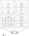
- Fig. 5 is a schematic illustration of an ADS-equipped vehicle 1 comprising an apparatus 10 for estimating a road geometry of a road upon which the vehicle 1 is traveling in accordance with some embodiments.
- the road geometry is described by a filter state that is tracked by a tracking filter, and the filter state comprises a plurality of road model hypotheses.
- each road model hypothesis is associated with a probability and comprises a parametrization of the road describing a geometry of one or more lanes of the road and wherein each lane of each road model hypothesis is associated with a probability of existence.
- a "vehicle” is any form of motorized transport.
- the vehicle 1 may be any road vehicle such as a car (as illustrated herein), a motorcycle, a (cargo) truck, a bus, etc.
- the apparatus 10 comprises control circuitry 11 and a memory 12.
- the control circuitry 11 may physically comprise one single circuitry device. Alternatively, the control circuitry 11 may be distributed over several circuitry devices. As an example, the apparatus 10 may share its control circuitry 11 with other parts of the vehicle 1 (e.g. the ADS 310). Moreover, the apparatus 10 may form a part of the ADS 310, i.e. the apparatus 10 may be implemented as a module or feature of the ADS.
- the control circuitry 11 may comprise one or more processors, such as a central processing unit (CPU), microcontroller, or microprocessor. The one or more processors may be configured to execute program code stored in the memory 12, in order to carry out various functions and operations of the vehicle 1 in addition to the methods disclosed herein.
- the processor(s) may be or include any number of hardware components for conducting data or signal processing or for executing computer code stored in the memory 12.
- the memory 12 optionally includes high-speed random access memory, such as DRAM, SRAM, DDR RAM, or other random access solid-state memory devices; and optionally includes non-volatile memory, such as one or more magnetic disk storage devices, optical disk storage devices, flash memory devices, or other non-volatile solid-state storage devices.
- the memory 12 may include database components, object code components, script components, or any other type of information structure for supporting the various activities of the present description.
- the memory 12 further stores map data 308.
- the map data 308 may for instance be used by the ADS 310 of the vehicle 1 in order to perform autonomous functions of the vehicle 1.
- the map data 308 may comprise high-definition (HD) map data.
- the memory 12, even though illustrated as a separate element from the ADS 310, may be provided as an integral element of the ADS 310.
- any distributed or local memory device may be utilized in the realization of the present inventive concept.
- the control circuitry 11 may be distributed e.g. such that one or more processors of the control circuitry 11 is provided as integral elements of the ADS 310 or any other system of the vehicle 1.
- the ADS 310 is configured carry out the functions and operations of the autonomous or semi-autonomous functions of the vehicle 1.
- the ADS 310 can comprise a number of modules, where each module is tasked with different functions of the ADS 310.
- the vehicle 1 comprises a number of elements which can be commonly found in autonomous or semi-autonomous vehicles. It will be understood that the vehicle 1 can have any combination of the various elements shown in Fig. 5 . Moreover, the vehicle 1 may comprise further elements than those shown in Fig. 5 . While the various elements is herein shown as located inside the vehicle 1, one or more of the elements can be located externally to the vehicle 1. For example, the map data may be stored in a remote server and accessed by the various components of the vehicle 1 via the communication system 326.
- the vehicle 1 further comprises a sensor system 320.
- the sensor system 320 is configured to acquire sensory data about the vehicle itself, or of its surroundings.
- the sensor system 320 may for example comprise a Global Navigation Satellite System (GNSS) module 322 (such as a GPS) configured to collect geographical position data of the vehicle 1.
- GNSS Global Navigation Satellite System
- the sensor system 320 may further comprise one or more sensors 324.
- the sensor(s) 324 may be any type of on-board sensors, such as cameras, LIDARs and RADARs, ultrasonic sensors, gyroscopes, accelerometers, odometers etc. It should be appreciated that the sensor system 320 may also provide the possibility to acquire sensory data directly or via dedicated sensor control circuitry in the vehicle 1.
- the vehicle 1 further comprises a communication system 326.
- the communication system 326 is configured to communicate with external units, such as other vehicles (i.e. via vehicle-to-vehicle (V2V) communication protocols), remote servers (e.g. cloud servers), databases or other external devices, i.e. vehicle-to-infrastructure (V2I) or vehicle-to-everything (V2X) communication protocols.
- the communication system 326 may communicate using one or more communication technologies.
- the communication system 326 may comprise one or more antennas (not shown). Cellular communication technologies may be used for long range communication such as to remote servers or cloud computing systems. In addition, if the cellular communication technology used have low latency, it may also be used for V2V, V2I or V2X communication.
- Examples of cellular radio technologies are GSM, GPRS, EDGE, LTE, 5G, 5G NR, and so on, also including future cellular solutions.
- GSM Global System for Mobile communications
- GPRS Global System for Mobile communications
- EDGE Evolved Universal Terrestrial Radio Access
- LTE Long Term Evolution
- 5G 5G NR
- future cellular solutions such as Wireless Local Area (LAN), e.g. IEEE 802.11 based solutions, for communicating with other vehicles in the vicinity of the vehicle 1 or with local infrastructure elements.
- LAN Wireless Local Area
- ETSI is working on cellular standards for vehicle communication and for instance 5G is considered as a suitable solution due to the low latency and efficient handling of high bandwidths and communication channels.
- the communication system 326 may accordingly provide the possibility to send output to a remote location (e.g. remote operator or control center) and/or to receive input from a remote location by means of the one or more antennas. Moreover, the communication system 326 may be further configured to allow the various elements of the vehicle 1 to communicate with each other. As an example, the communication system may provide a local network setup, such as CAN bus, I2C, Ethernet, optical fibers, and so on. Local communication within the vehicle may also be of a wireless type with protocols such as WiFi, LoRa, Zigbee, Bluetooth, or similar mid/short range technologies.
- the vehicle 1 further comprises a maneuvering system 320.
- the maneuvering system 328 is configured to control the maneuvering of the vehicle 1.
- the maneuvering system 328 comprises a steering module 330 configured to control the heading of the vehicle 1.
- the maneuvering system 328 further comprises a throttle module 332 configured to control actuation of the throttle of the vehicle 1.
- the maneuvering system 328 further comprises a braking module 334 configured to control actuation of the brakes of the vehicle 1.
- the various modules of the maneuvering system 328 may also receive manual input from a driver of the vehicle 1 (i.e. from a steering wheel, a gas pedal and a brake pedal respectively).
- the maneuvering system 328 may be communicatively connected to the ADS 310 of the vehicle, to receive instructions on how the various modules of the maneuvering system 328 should act.
- the ADS 310 can control the maneuvering of the vehicle 1, for example via the decision and control module 318.
- the ADS 310 may comprise a localization module 312 or localization block/system.
- the localization module 312 is configured to determine and/or monitor a geographical position and heading of the vehicle 1, and may utilize data from the sensor system 320, such as data from the GNSS module 322. Alternatively, or in combination, the localization module 312 may utilize data from the one or more sensors 324.
- the localization system may alternatively be realized as a Real Time Kinematics (RTK) GPS in order to improve accuracy.
- RTK Real Time Kinematics
- the ADS 310 may further comprise a perception module 314 or perception block/system 314.
- the perception module 314 may refer to any commonly known module and/or functionality, e.g. comprised in one or more electronic control modules and/or nodes of the vehicle 1, adapted and/or configured to interpret sensory data - relevant for driving of the vehicle 1 - to identify e.g. obstacles, vehicle lanes, relevant signage, appropriate navigation paths to be executed by the path planning module 316 etc.
- the perception module 314 may thus be adapted to rely on and obtain inputs from multiple data sources, such as automotive imaging, image processing, computer vision, and/or in-car networking, etc., in combination with sensory data e.g. from the sensor system 320.
- the localization module 312 and/or the perception module 314 may be communicatively connected to the sensor system 320 in order to receive sensory data from the sensor system 320.
- the localization module 312 and/or the perception module 314 may further transmit control instructions to the sensor system 320.
- the apparatus 10 comprises control circuitry 11 configured to, for each time step out of a plurality of consecutive time steps, predict a filter state by determining a probability of each road model hypothesis based on vehicle motion data and a prior filter state determined at a preceding time step.
- the control circuitry 11 is further configured to associate road features obtained from perception data derived from an output of one or more vehicle-mounted sensors with the parametrization of the road of each road model hypothesis of the predicted filter state.
- the control circuitry 11 is configured to determine an existence probability for each lane of each road model hypothesis based on a prior existence probability for each corresponding lane determined at the preceding time step and the road feature association.
- the control circuitry is further configured to determine a probability of each road model hypothesis of the plurality of road model hypotheses based on the prior filter state determined at the preceding time step and the determined existence probability of each lane of that road model hypothesis, select the road model hypothesis associated with the highest probability based on the determined probability of each road model hypothesis, and output a road model based on the parametrization of the road of the selected road model hypothesis.
- a non-transitory computer-readable storage medium storing one or more programs configured to be executed by one or more processors of a processing device, the one or more programs comprising instructions for performing the method according to any one of the above-discussed embodiments.
- a cloud computing system can be configured to perform any of the methods presented herein.
- the cloud computing system may comprise distributed cloud computing resources that jointly perform the methods presented herein under control of one or more computer program products.
- a computer-accessible medium may include any tangible or non-transitory storage media or memory media such as electronic, magnetic, or optical media-e.g., disk or CD/DVD-ROM coupled to computer system via bus.
- tangible and non-transitory are intended to describe a computer-readable storage medium (or “memory”) excluding propagating electromagnetic signals, but are not intended to otherwise limit the type of physical computer-readable storage device that is encompassed by the phrase computer-readable medium or memory.
- the terms “non-transitory computer-readable medium” or “tangible memory” are intended to encompass types of storage devices that do not necessarily store information permanently, including for example, random access memory (RAM).
- Program instructions and data stored on a tangible computer-accessible storage medium in non-transitory form may further be transmitted by transmission media or signals such as electrical, electromagnetic, or digital signals, which may be conveyed via a communication medium such as a network and/or a wireless link.
- transmission media or signals such as electrical, electromagnetic, or digital signals, which may be conveyed via a communication medium such as a network and/or a wireless link.
- the processor(s) 11 may be or include any number of hardware components for conducting data or signal processing or for executing computer code stored in memory 12.
- the device 10 has an associated memory 12, and the memory 12 may be one or more devices for storing data and/or computer code for completing or facilitating the various methods described in the present description.
- the memory may include volatile memory or non-volatile memory.
- the memory 12 may include database components, object code components, script components, or any other type of information structure for supporting the various activities of the present description. According to an exemplary embodiment, any distributed or local memory device may be utilized with the systems and methods of this description.
- the memory 12 is communicably connected to the processor 11 (e.g., via a circuit or any other wired, wireless, or network connection) and includes computer code for executing one or more processes described herein.
- parts of the described solution may be implemented either in the vehicle 1, in a system located external the vehicle 1, or in a combination of internal and external the vehicle; for instance in a server in communication with the vehicle, a so called cloud solution.
- the different features and steps of the embodiments may be combined in other combinations than those described.
Landscapes
- Engineering & Computer Science (AREA)
- Physics & Mathematics (AREA)
- Theoretical Computer Science (AREA)
- Multimedia (AREA)
- General Physics & Mathematics (AREA)
- Software Systems (AREA)
- Mathematical Physics (AREA)
- Automation & Control Theory (AREA)
- Mechanical Engineering (AREA)
- Transportation (AREA)
- Databases & Information Systems (AREA)
- Computing Systems (AREA)
- Computer Vision & Pattern Recognition (AREA)
- Artificial Intelligence (AREA)
- Health & Medical Sciences (AREA)
- General Health & Medical Sciences (AREA)
- Evolutionary Computation (AREA)
- Medical Informatics (AREA)
- Human Computer Interaction (AREA)
- Probability & Statistics with Applications (AREA)
- Traffic Control Systems (AREA)
Abstract
A computer-implemented method for estimating a road geometry of a road upon which a vehicle is traveling and related aspects are disclosed. The disclosed embodiments provide a model-based technique for estimating a road model having an arbitrary number of lanes on a road as well as any entrance lanes (i.e. on-ramp or slip roads) and exit lanes (i.e. off ramps or off-slip roads). In more detail, the herein disclosed embodiments utilize a Bayesian approach to multi-lane tracking in various traffic scenarios, such as e.g. highway scenarios. The employed model-based algorithm estimates the lane center curves of multi-lane roads based on vehicle motion data (e.g. speed, angular velocity) and perception data (e.g. camera output, lidar output, radar output, etc.) that comprises detected road features (e.g. lane markers, road edges, road barriers, guard rails, road markers, etc.) or other objects (e.g. other road users).
Description
- The disclosed technology relates to methods, apparatuses and related aspects for estimating a road model for a vehicle traveling on a road. In particular, but not exclusively the disclosed technology relates to a model-based algorithm to estimate center curves of a multi-lane road as well as on-ramps and off-ramps to and from the multi-lane road.
- During the last few years, the research and development activities related to autonomous vehicles have exploded in number and many different approaches are being explored. An increasing portion of modern vehicles have advanced driver-assistance systems (ADAS) to increase vehicle safety and more generally road safety. ADAS - which for instance may be represented by adaptive cruise control (ACC) collision avoidance system, forward collision warning, etc. - are electronic systems that may aid a vehicle driver while driving. Today, there is ongoing research and development within a number of technical areas associated to both the ADAS and the Autonomous Driving (AD) field. ADAS and AD will herein be referred to under the common term Automated Driving System (ADS) corresponding to all of the different levels of automation as for example defined by the SAE J3016 levels (1 - 5) of driving automation, and in particular for
level 3, 4 and 5. - As computer hardware in vehicles continue to progress, it allows for an increasing amount of effort to be put into the development of Automated Driving Systems, and many active safety systems such as ACCs and Lane Support Systems (LSSs) are reliant on having some knowledge of the road surrounding the vehicle. Thus, increasing the accuracy and redundancy in road estimation systems may therefore be crucial for improving driver safety and comfort.
- The herein disclosed technology seeks to mitigate, alleviate or eliminate one or more of the above-identified deficiencies and disadvantages in the prior art to address various problems relating to performance in complex environments and redundancy.
- Various aspects and embodiments of the disclosed invention are defined below and in the accompanying independent and dependent claims.
- A first aspect of the disclosed technology comprises a computer-implemented method for estimating a road geometry of a road upon which a vehicle is traveling, where the road geometry is described by a filter state that is tracked by a tracking filter. The filter state comprises a plurality of road model hypotheses, wherein each road model hypothesis is associated with a probability and comprises a parametrization of the road describing a geometry of one or more lanes of the road and where each lane of each road model hypothesis is associated with a probability of existence. The method comprises, for each time step out of a plurality of consecutive time steps, predicting a filter state by determining a probability density of each road model hypothesis based on vehicle motion data and a prior filter state determined at a preceding time step. Further, the method comprises associating road features obtained from perception data derived from an output of one or more vehicle-mounted sensors with the parametrization of the road of each road model hypothesis of the predicted filter state. The method further comprises determining an existence probability for each lane of each road model hypothesis based on a prior existence probability for each corresponding lane determined at the preceding time step and the road feature association, and determining a probability of each road model hypothesis of the plurality of road model hypotheses based on the prior filter state determined at the preceding time step and the determined existence probability of each lane of that road model hypothesis. Furthermore, the method comprises selecting the road model hypothesis associated with the highest probability based on the determined probability of each road model hypothesis, and outputting a road model based on the parametrization of the road of the selected road model hypothesis.
- A second aspect of the disclosed technology comprises a computer program product comprising instructions which, when the program is executed by a computing device of a vehicle, causes the computing device to carry out the method according to any one of the embodiments of the first aspect disclosed herein. With this aspect of the disclosed technology, similar advantages and preferred features are present as in the other aspects.
- A third aspect of the disclosed technology comprises a (non-transitory) computer-readable storage medium comprising instructions which, when executed by a computing device of a vehicle, causes the computing device to carry out the method according to any one of the embodiments of the first aspect disclosed herein. With this aspect of the disclosed technology, similar advantages and preferred features are present as in the other aspects.
- The term "non-transitory," as used herein, is intended to describe a computer-readable storage medium (or "memory") excluding propagating electromagnetic signals, but are not intended to otherwise limit the type of physical computer-readable storage device that is encompassed by the phrase computer-readable medium or memory. For instance, the terms "non-transitory computer readable medium" or "tangible memory" are intended to encompass types of storage devices that do not necessarily store information permanently, including for example, random access memory (RAM). Program instructions and data stored on a tangible computer-accessible storage medium in non-transitory form may further be transmitted by transmission media or signals such as electrical, electromagnetic, or digital signals, which may be conveyed via a communication medium such as a network and/or a wireless link. Thus, the term "non-transitory", as used herein, is a limitation of the medium itself (i.e., tangible, not a signal) as opposed to a limitation on data storage persistency (e.g., RAM vs. ROM).
- A fourth aspect of the disclosed technology comprises an apparatus for estimating a road geometry of a road upon which a vehicle is traveling, where the road geometry is described by a filter state that is tracked by a tracking filter. The filter state comprising a plurality of road model hypotheses, where each road model hypothesis is associated with a probability and comprises a parametrization of the road describing a geometry of one or more lanes of the road and wherein each lane of each road model hypothesis is associated with a probability of existence. The apparatus comprises control circuitry configured to, for each time step out of a plurality of consecutive time steps, predict a filter state by determining a probability of each road model hypothesis based on vehicle motion data and a prior filter state determined at a preceding time step. The control circuitry is further configured to associate road features obtained from perception data derived from an output of one or more vehicle-mounted sensors with the parametrization of the road of each road model hypothesis of the predicted filter state. Moreover, the control circuitry is configured to determine an existence probability for each lane of each road model hypothesis based on a prior existence probability for each corresponding lane determined at the preceding time step and the road feature association, and determine a probability of each road model hypothesis of the plurality of road model hypotheses based on the prior filter state determined at the preceding time step and the determined existence probability of each lane of that road model hypothesis. The control circuitry is further configured to select the road model hypothesis associated with the highest probability based on the determined probability of each road model hypothesis, and output a road model based on the parametrization of the road of the selected road model hypothesis.With this aspect of the disclosed technology, similar advantages and preferred features are present as in the other aspects.
- A fifth aspect of the disclosed technology comprises a vehicle comprising an apparatus according to any one of the embodiments disclosed herein. With this aspect of the disclosed technology, similar advantages and preferred features are present as in the other aspects.
- The disclosed aspects and preferred embodiments may be suitably combined with each other in any manner apparent to anyone of ordinary skill in the art, such that one or more features or embodiments disclosed in relation to one aspect may also be considered to be disclosed in relation to another aspect or embodiment of another aspect.
- Further embodiments are defined in the dependent claims. It should be emphasized that the term "comprises/comprising" when used in this specification is taken to specify the presence of stated features, integers, steps, or components. It does not preclude the presence or addition of one or more other features, integers, steps, components, or groups thereof.
- These and other features and advantages of the disclosed technology will in the following be further clarified with reference to the embodiments described hereinafter.
- The above aspects, features and advantages of the disclosed technology, will be more fully appreciated by reference to the following illustrative and non-limiting detailed description of example embodiments of the present disclosure, when taken in conjunction with the accompanying drawings, in which:
-
Fig. 1 is a schematic illustration of a Bayesian network representation of a state space model. -
Fig. 2 is a set of schematic illustration of a road parametrization in accordance with some embodiments. -
Fig. 3a is a schematic illustration of an image frame taken by a front-facing vehicle mounted camera with re-projected lane marking points. -
Fig. 3b is a schematic illustration of a bird's eye view of the 3D lane marking points which were detected re-projected into the camera image ofFig. 3a . -
Fig. 4 is a schematic flowchart representation of a method for estimating a road geometry of a road upon which a vehicle is traveling in accordance with some embodiments. -
Fig. 5 is a schematic block-diagram representation of a vehicle comprising an apparatus for estimating a road geometry of a road upon which a vehicle is traveling in accordance with some embodiments. - The present disclosure will now be described in detail with reference to the accompanying drawings, in which some example embodiments of the disclosed technology are shown. The disclosed technology may, however, be embodied in other forms and should not be construed as limited to the disclosed example embodiments. The disclosed example embodiments are provided to fully convey the scope of the disclosed technology to the skilled person. Those skilled in the art will appreciate that the steps, services and functions explained herein may be implemented using individual hardware circuitry, using software functioning in conjunction with a programmed microprocessor or general-purpose computer, using one or more Application Specific Integrated Circuits (ASICs), using one or more Field Programmable Gate Arrays (FPGA) and/or using one or more Digital Signal Processors (DSPs).
- It will also be appreciated that when the present disclosure is described in terms of a method, it may also be embodied in apparatus comprising one or more processors, one or more memories coupled to the one or more processors, where computer code is loaded to implement the method. For example, the one or more memories may store one or more computer programs that causes the apparatus to perform the steps, services and functions disclosed herein when executed by the one or more processors in some embodiments.
- It is also to be understood that the terminology used herein is for purpose of describing particular embodiments only, and is not intended to be limiting. It should be noted that, as used in the specification and the appended claim, the articles "a", "an", "the", and "said" are intended to mean that there are one or more of the elements unless the context clearly dictates otherwise. Thus, for example, reference to "a unit" or "the unit" may refer to more than one unit in some contexts, and the like. Furthermore, the words "comprising", "including", "containing" do not exclude other elements or steps. It should be emphasized that the term "comprises/comprising" when used in this specification is taken to specify the presence of stated features, integers, steps, or components. It does not preclude the presence or addition of one or more other features, integers, steps, components, or groups thereof. The term "and/or" is to be interpreted as meaning "both" as well and each as an alternative.
- It will also be understood that, although the term first, second, etc. may be used herein to describe various elements or features, these elements should not be limited by these terms. These terms are only used to distinguish one element from another. For example, a first signal could be termed a second signal, and, similarly, a second signal could be termed a first signal, without departing from the scope of the embodiments. The first signal and the second signal are both signals, but they are not the same signal.
- The herein disclosed technology provides a model-based technique for estimating a road model having an arbitrary number of lanes on a road as well as any entrance lanes (i.e. on-ramp or slip roads) and exit lanes (i.e. off ramps or off-slip roads). In more detail, the herein disclosed embodiments utilize a Bayesian approach to multi-lane tracking in various traffic scenarios, such as e.g. highway scenarios. The employed model-based algorithm estimates the lane center curves of multi-lane roads based on vehicle motion data (e.g. speed, angular velocity) and perception data (e.g. camera output, lidar output, radar output, etc.) that comprises detected road features (e.g. lane markers, road edges, road barriers, guard rails, road markers, etc.) or other objects (e.g. other road users).
- In particular, in accordance with some embodiments, the herein disclosed technology utilizes a road parametrization that supports describing any number of lanes, on-ramps, and off-ramps and the road parametrization is suitable for tracking with a Bayesian filter. In particular, embodiments herein use a multiple hypothesis coupled multi-object tracking filter for the parametrization of the road. Multiple hypotheses are used to deal with data association from detection of road features and coupling lanes are used to model parallel lanes. Furthermore, some embodiments deal with object spawning (i.e. lane spawning) and death giving each lane within each hypothesis a probability of existence.
- In the context of the present disclosure, the term "road model" refers to a digital representation or virtual model of the road environment. It is considered to be a crucial component used by autonomous vehicles to perceive and understand the surrounding road conditions. The road model typically includes various elements such as the geometry of the road and lane markings, an may further include traffic signs, traffic lights, obstacles, and other relevant features. The road model serves as a reference for the automated driving system to make decisions and navigate the vehicle safely. It allows the system to determine the vehicle's position, plan its trajectory, detect and track objects, interpret traffic signs and signals, and anticipate potential hazards or obstacles on the road. By continuously updating and analyzing the road model in real-time, the ADS can adapt to changing road conditions, make appropriate driving decisions, and ensure the safety and efficiency of the vehicle's operation.
- In the following, relevant background theory and other details are presented in order to facilitate the understanding of the herein disclosed embodiments.
- There are multiple interpretations of the concept of probability, of which Bayesian probability is one. In the framework, all events have a prior probability of occurring which allows for expressing the probability of an event even when none or finitely many experiments have been done to test the ratio between positive and negative outcomes. Crucial to Bayesian probability is Bayes theorem

- For the purpose of state estimation, we assume our control system is described by a discrete state space model. In each time step k we typically represent the state estimate by a random variable xk and receive measurements also in the form of a random variable yk. A Bayesian network representation of a state space model is shown in
Fig. 1 . This figure visualizes some conditional independencies between the random variables which follows from the state space representation, specifically

- The goal of the Bayesian state estimation is to express the posterior state density p(xk |y 1:k ) given measurements from
time 1 to k and a prior p(x k-1|y 1:k-1). However, to find p(xk |y 1:k ) one first seeks an expression for p(xk |y 1:k-1). Using equation (1.2) and the law of total probability one arrives at what is known as the Chapman-Kolmogorov equation
Fig. 1 . - Further, equation (1.3) in combination with Bayes theorem, i.e. equation (1.1) gives

- Here, p(yk |xk ) is known as the measurement likelihood. Since one is generally interested in the density with respect to xk one can view the denominator of equation (1.5) as a constant normalization factor and discard it. It can however later be recreated by enforcing that p(xk |y 1:k ) should integrate to one.
- Thus, the basic building blocks of a generic Bayesian state estimator have been laid down. In time step k given a prior density p(x k-1|y 1:k-1) one first performs what is known as the prediction step of the estimation by applying the Chapman-Kolmogorov equation (1.4) to obtain p(xk |y 1:k-1). From a known expression of the measurement likelihood one next performs what is known as the update step by applying equation (2.5) to obtain p(yk |xk ). This process is then repeated recursively for time steps k+1, k+2, and so on. For the initial time step, an expression for the initial prior p(xo) needs to be provided.
- The Kalman filter is a Bayesian state estimator specialized for linear and Gaussian systems. A linear Gaussian state space model is given by


- It can be shown that the state estimates will also be Gaussian distributed for all time steps, i.e.


- As such, the Kalman filter is a conjugate prior filter, meaning the prior and posterior densities are of the same family, Gaussian in this case. For linear and Gaussian systems, it can also be shown that the Bayesian state estimation equations specializes to
-


-


- Here, x̂ a|b represents the estimate of x at time a given the observations up to and including time b ≤ a. Moreover equation (1.10a) is the predicted state estimate, equation (1.10b) is the predicted covariance estimate, equation (1.10c) is the innovation or measurement residual, equation (1.10d) is the innovation or residual covariance, equation (1.10e) is the Kalman gain, equation (1.10f) is the updated state estimate, equation (1.10g) is the updated covariance estimate.
- The Extended Kalman Filter (EKF) is a variation of the Kalman filter adapted for nonlinear state space models given by


- The process and measurement noises qk and rk are as in the ordinary Kalman filter. In every time step the motion and measurement models are linearized around the mean of the prior. The ordinary Kalman filter equations are then applied to the linearization. This results in an approximate solution to the state estimation problem where all densities are assumed to be Gaussian. The full EKF equations are given as
-


-


- Similar as before, equation (1.13a) is the predicted state estimate, equation (1.13b) is the predicted covariance estimate, equation (1.13c) is the innovation or measurement residual, equation (1.13d) is the innovation or residual covariance, equation (1.13e) is the Kalman gain, equation (1.13f) is the updated state estimate, equation (1.13g) is the updated covariance estimate.
- Filters such as the Kalman filter and its variants are suitable for tracking the state of a single object, such as a car or other vehicle, in environments with no clutter, i.e. where every measurement is known to originate from the tracked object. However, many real-world scenarios involve sensors which introduce clutter, or sometimes don't detect the real object.
- A typical example to illustrate clutter and the possibility of not detecting the tracked object is the use of a radar sensor to track a single airplane. Every time the radar is polled it returns a variable length list of distance angle detection pairs made since the last time step. Even given that we know for sure that only one airplane is present within the field of view of the radar, the sensor when polled may yield zero, one, or multiple detections due to disturbances. This stands in contrast to simple sensors such as those comprised in Inertial Measurement Units (IMUs) and encoders which always return a fixed size data structure when polled. Those radar detections which are due to disturbances and not associated to the object we desire to track are called clutter. Given a set of detections from the radar, it is also possible that none of them correspond to the true object. This would obviously be the case if the radar did not detect anything at the current time step, and could for example be the result of the object holding an unfavourable angle to the radar, or that something is blocking the view from the radar to the object. In order to for example make use of such sensors as the radar in a tracking system, methods of handling clutter and missed detections need to be formulated.
- One way to deal with clutter is to simply discard detections that are unlikely to originate from the plane given the prior. This is known as gating. Gating forms an important part of clutter rejection measures in many more complex filters. Using gating on its own to deal with clutter may be feasible in scenarios with low clutter intensities, however as the amount of clutter increases it becomes more important to model the clutter in order to reject it with higher accuracy. One commonly used model of clutter is the Poisson Point Process (PPP). In this model, the clutter measurements are independent and identically distributed. At each time step, the number of clutter measurements n in the volume V surveillance by the sensors is Poisson distributed with expected value
λ . In addition to introducing clutter measurements, an imperfect sensor may also not detect the tracked object at each time step. This property may be modelled with a Bernoulli Process. Using the Bernoulli Process model, at time step k, the object is detected with probability ρ and undetected with probability 1 - ρ. Given that the object is detected, it is distributed according to some distribution with probability density function g(y). - Further, the Multi-Bernoully Mixture (MBM) filter is an algorithm for tracking multiple separate objects in the presence of clutter. The MBM filter represents the state as a superposition of hypotheses, where each hypothesis is a union of Bernoulli Processes. Each such Bernoulli Process may be interpreted as one possible object to track.
- As mentioned, methods and apparatuses of the embodiments disclosed herein estimate a road geometry by estimating lane centers of the lanes of the road. In accordance with some embodiments, the curve of the lane center are parametrized using clothoid splines, polynomials, or lateral offsets at fixed longitudinal positions. Even though the present description may be focused on lane center parametrization using clothoid splines, it is readily understood by the skilled person in the art that other parametrizations are feasible.
- In general, a clothoid is a 2D curve with constant rate of curvature change along the curve. A clothoid spline is thus a connection of multiple clothoid curves constrained such that the curvature is continuous. To find the geometry of the clothoid spline, the following differential equation may be solved:

- In some embodiments, the center line parametrization comprises 3D clothoid splines. This may be advantageous in scenarios where the perception data derived from the output of one or more vehicle-mounted sensors comprises 3D road feature coordinates. Accordingly, equation (1.15) may be extended to 3D according to

- A visualization of the parametrization of the road (i.e. "road model") in accordance with some embodiments is depicted in
Fig. 2 . Each subfigure (a)-(d) inFig. 2 shows a different subset of the parametrization parameters in accordance with some embodiments. In the depicted example ofFig. 2 , the road has two main road lanes and one branch lane. The center line curvature and width of the lanes are described by splines. The main road splines have four segments and the branch has three segments as illustrated in subfigure (b), i.e. in the top-right subfigure. In this bird's eye view (or top view) the parameters controlling the vertical position of the road are omitted for visual clarity. In short, the parameters y, x and αi are distances, φi are angles, ki are curvatures, and
- Starting from the description of the ego-lane center as a 3D clothoid parametrized by curvatures


- The width parametrization may comprise a constant value, that may for example be predefined based on regulations in the geographical jurisdiction of the vehicle (e.g. 10-11 feet for the US or 2,5-3,25 meters in Europe). However, in some embodiments the width parametrization may comprise a function of length (of the lane).
- Furthermore, branch lanes may be introduced to the parametrization of the road in order to estimate the center of the lanes merging into or diverging from the main road. A branch b can attach to any one of the main road lanes, mb, at a parameter-controlled distance ab along the main road lane, and angles φb to the connecting main road lane. From the root of the branch, its curve and similarly to the ego-lane can be described by a 3D clothoid spline with curvatures


- Further, the pose of the ego-vehicle in relation to the road may be parametrized. This may be done by describing the vehicle pose in relation to the
starting point 201 of the ego-lane center. The ego-vehicle pose may be given by three spatial coordinates x, y, and z as well as three Tait-Bryan angles φ, θ and ψ representing yaw, pitch, and roll respectively. - As mentioned, the road parametrization proposed herein comprises a lane center parametrization for each lane of the road and a width parametrization for each lane of the road. This is in contrast to many conventional road model estimation techniques whose road parametrization is focused on lane delimiters. However, an advantage of having a road parametrization focusing on a lane center parametrization and a width parametrization rather than lane delimiter parametrization is that one gets improved performance in situations where there are no lane delimiters near the road edges. Moreover, lane center estimations are directly consumed by downstream functions of an ADS, such as path planning functions as they are generally configured to steer the vehicle based on the lane center estimate. Moreover, the tracking filter is more robust as it allows for using measurement data (i.e. perception data) in the form of vehicle detections as it can be assumed that other vehicles attempt to center themselves in a lane and that the vehicle detections therefore can be associated to the lane centers of the road parametrization. Moreover, another advantage of having a road parametrization focusing on a lane center parametrization and a width parametrization rather than lane delimiter parametrization is that complex road geometries with branch lanes are easier to model while it is generally challenging to connect branch lanes to the appropriate main road lane when using a road parametrization focused on lane delimiters.
- To formulate the dynamic model one may define the state space representation of the parametrization of the road (i.e. the road model). All continuous parameters of the parametrization of the road, those being x, y, z, φ, θ, ψ, φb, θb,


- Still further, a geometry state transition model may be defined in order to describe the expected change in parameter values from one time step to the next based on the control signal. Neglecting process noise, the motion model may comprise updating the ego vehicle pose,


- To account for that the number of lanes in the road may increase from one time step to the next, the state transition adds some new lanes to the state every time step. In some embodiments, the tracking filter may apply a lane spawning model where the lane spawning is based on an assumption that the number of lanes does not grow very rapidly. Thus, these new lanes are given a low probabilities of existence ρc. In some embodiments, single additional main road lanes at the very left and very right of the main road are spawned. The state parameters controlling the width of the main road lanes as well as the indices mi are shifted over accordingly. Furthermore, with regards to the spawning of branch lanes, one may spawn one diverging and one merging branch lane starting from the rightmost main road lane with sufficient width and existence probability. For computational performance reasons one can neglect spawning of branches to the left of the main road, in particular for highway scenarios, as such on ramps or off ramps are not common in places where one drives on the right side of the road. Thus, the addition or spawning of branch lanes may be dependent on local traffic regulations (i.e. if the current the current geographical jurisdiction of the vehicle applies right-side traffic or left-side traffic).
- Furthermore, in some embodiments, the tracking filter may apply a lane death model. In more detail, a probability of survival PS representing the probability that each individual lane survives from one time step to the next, is introduced. The probability of survival is then used to update the probabilities of existence of each lane according to

- Additionally, lanes whose width is below some threshold and branches where ab has become negative may be removed from the filter state.
- The geometry state transition model, the lane spawning model, and the lane death model may be summarized in three transition equations




- Furthermore, a measurement model is provided that describes the measurements ŷ, here the coordinates of the points of the road features (e.g. lane markings) one would expect to receive given a value of the state vector. In some embodiments of the herein proposed model, except for clutter, lane marking measurements may only occur on either edge of a lane, separated from the lane center by half the width of the lane. These lines may be known as delimiters. The process of associating real measurements to delimiters of the model is handled by the filter, and further discussed below. For notational brevity, the time step index k is dropped in reference to the measurement model discussion. Also, the following discussion will be focused on road features in terms of lane markings or delimiters for illustrative purposes. However, this should not be interpreted as that the measurement model is limited to measurement data comprising road features in terms of lane markings but may additionally or alternatively include other road features, and even other objects (i.e. other vehicles).
-
Fig. 3a is a schematic illustration of an image captured by a front-facing vehicle-mounted camera where re-projected lane marker detections have been added. The detections illustrate typical output of a 3D lane marking detection algorithm.Fig. 3b is a bird's eye view of the same 3D lane marking points which were re-projected into the camera image. In more detail, the output of a 3D lane marking detection algorithm is a set of 3D coordinates along with uncertainty estimates of these coordinates. Since uncertainty estimates are generally provided in the output of the 3D lane marking detection they are suitable for use as measurements in the update step of the herein proposed tracking filter. - Moreover, only existing delimiters can be detected. From ρ one can only directly get the probability that each lane center exists, but here one can assume that given that a lane exists, both its right and left delimiters also exist. Of the existing delimiters each has a probability PD being detected. A detected delimiter gives off at least one measurement, while an undetected delimiter gives of no measurements. In the following the measurements given off by each detected delimiter is described.
- As depicted in
Fig. 2 , the parametrization of the road model in accordance with some embodiments, provide a description of the geometry of the delimiters in the local coordinate frame of the ego-road. As the delimiters of the main road are described in relation to ego-lane center, the geometry of this center line is needed. This may for example be done by integrating equation (1.16) for the lane center parameters using the Euler method with step size Δl, with the initial condition for coordinates and angles set to zero as one is working in the local coordinate frame of the ego-road. From this one gets


- Similar differential equations, this time for linear splines instead of clothoid splines are solved in the same manner in order to get the sequence of widths (w 0m,i ) i corresponding to (〈x 0,i , y 0,i , z 0,i , φ0,i , θ 0,i,l
0,i 〉) i of the different main road lanes. One is now able to give the coordinates of points on the main road delimiters as

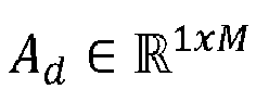

- The coordinates of a point on the branch lanes may be computed in a similar fashion by first solving the differential equations of the center line parametrization (e.g. clothoid) and lane width parametrization using the Euler method. An initial condition for the center line parametrization, the position is calculated by linear interpolation of the center polyline of the parent main road lane (which is computed similarly to equation (1.22) but with A matrices modified accordingly) a distance ab along the ego-lane center (see e.g. subfigure (c) of
Fig. 2 ). The initial angle is similarly computed by interpolating the main road lane angles, and then adding the initial angles φb and θb of the branch. The initial curvatures are directly given as

- In the foregoing the description of the road geometry is given in relation to the road frame. However, the measurements (i.e. perception data) is generally given in the ego-vehicle frame. This frame is aligned with the vehicle with its origin on the center of the rear axle, the x-axis pointing forward, the y-axis left along the rear axle, and z-axis upwards. However, the parameters of the ego-vehicle pose, x, y, z and φ, θ, ψ can be transformed to the road-aligned lane delimiter geometry (rd,i ) i into the ego-vehicle frame, resulting in the sequences

- Lane marking detections are assumed to be produced by the points along the polylines defined by


- With the road model defined, one then has to design a filter to estimate the parameters of the road model. In accordance with some embodiments, the tracking filter is a multiple hypothesis tracker. In each hypothesis h, the x portion of the state is represented by a single Gaussian density with mean x̂h and the covariance matrix Ph. Thus, all the lane of the road are coupled. The rest of the state, ξ and ρ are assumed to be known and equal to ξ̂ and ρ̂ respectively within each hypothesis. The uncertainty in these variables thus comes from having multiple hypotheses.
- The prior state density of the filter can be described by


- In order to simplify the computation, one can assume that the probability of survival PS is constant and lane independent, and a PPP clutter model may be used with constant intensity λC . The filter algorithm itself may further support state dependent probabilities of survival and other clutter models than the PPP. For the probability of detection one can let it be state dependent such that it is greater for lane in front of, and near, the ego-vehicle and trails off outside this region. Moreover, in order to simplify the computation, one does not need to evaluate the probability of detection for the entire state density, but only evaluate it for the estimation mean x̂.
-
Fig. 4 is a schematic flowchart representation of a method S100 for estimating a road geometry of a road upon which a vehicle is traveling. The road geometry is described by a filter state that is tracked by a tracking filter, where the filter state comprises a plurality of road model hypotheses. The tracking filter may be referred to as a multiple hypothesis multi-object tracking filter that is designed to track the filter state. Moreover, each road model hypothesis is associated with a probability and also comprises a parametrization of the road describing a geometry of one or more lanes of the road and each lane of each road model hypothesis is associated with a probability of existence. Accordingly, the filter state contains a probability density over the parameters of the road parametrization. Stated differently, the filter state is described by a set of hypotheses corresponding to configurations of the road model (i.e. the parametrization of the road), and each hypothesis has an associated probability. However, within each hypothesis, each lane has a probability of existence. - Furthermore, as mentioned in the foregoing, the tracked "objects" of the tracking filter are lane centers and lane widths in accordance with some embodiments. Thus, the tracking filter does not track lane markers. However, it follows from knowing the geometries of the lane centers and widths that one can describe the left and right borders of the lanes, which is where one would expect lane markers to appear. Moreover, the tracking filter is hypothesis oriented, and not track oriented. Also, all parameters of the road model (i.e. the parametrization of the road) are coupled.
- The method S100 is preferably a computer-implemented method S100, performed by a processing system of the ADS-equipped vehicle. The processing system may for example comprise one or more processors and one or more memories coupled to the one or more processors, wherein the one or more memories store one or more programs that perform the steps, services and functions of the method S100 disclosed herein when executed by the one or more processors.
- The method S100 is performed as a loop and the method steps are repeated with some sample frequency (e.g. 10 Hz, 20 Hz, 50 Hz, etc.) depending on the set requirements and/or available computational power and/or available memory resources. Thus, for each time step out of a plurality of consecutive time steps, the method S100 comprises predicting S101 a filter state by determining a probability density of each road model hypothesis based on vehicle motion data and a prior filter state determined at a preceding time step. In some embodiments, the prediction S101 step comprises making an Extended Kalman Filter (EKF) prediction of a state estimate and a covariance estimate for all hypothesis using a motion model accounting for the prior filter state, such as e.g. the motion model defined in equation (1.20a). Here, the vectors ξ and ρ can be updated according to equations (1.19a) and (1.19b) respectively. The weight of each hypothesis may be left unchanged. In some embodiments, the vehicle motion data comprises a vehicle speed at the time step. However, the vehicle motion data may further comprise a yaw rate, a roll rate, and/or a pitch rate at the time step.
- In some embodiments, the method S100 comprises adding S108 one or more main road lanes and/or one or more branch lanes to each road model hypothesis of the predicted S101 filter state. Each of these added S108 lanes comprise a corresponding parametrization (e.g. having a lane center parametrization and a lane width parametrization). The added S108 lanes may be construed as candidates for new lanes that have not yet been detected. Moreover, in accordance with some embodiments, the method S100 further comprises tagging S109 the added S108 one or more main road lanes and/or one or more branch lanes. By tagging S109 the added S108 lanes, one facilitates the subsequent removal of added S108 lanes that are not associated with any road features obtained from perception data.
- The method S100 further comprises associating S102 road features obtained from perception data derived from an output of one or more vehicle-mounted sensors with the parametrization of the road of each road model hypothesis of the predicted filter state. This may also be referred to as data association S102. In some embodiments, the road features obtained from perception data derived from an output of one or more vehicle-mounted sensors comprises lane marking detections obtained from a lane tracking algorithm configured to output coordinates of lane markers depicted in images output from a vehicle-mounted camera.
- The term "perception data" refers to the information gathered by sensors and other technologies that are used by ADS-equipped vehicles to detect and interpret their environment. This includes data collected from cameras, lidar, radar, and other sensors that help the vehicle "perceive" its surroundings and make decisions based on that information. The perception data collected by the vehicle may include the position, speed, and direction of nearby objects, position and type of road markings, position and type of traffic signs, and other relevant information. This data may then be processed by the vehicle's onboard computer to help it make decisions on steering, acceleration, braking, and other actions necessary to safely navigate the environment. Accordingly, the term "perception" data may refer to "surroundings assessment" data, "spatial perception" data, "processed sensory" data and/or "temporal dependencies" data, whereas perception "data" may refer to perception "information" and/or "estimates". The term "obtained" from a perception module or perception system, on the other hand, may refer to "derived" from a perception model and/or "based on output data" from a perception module or system, whereas perception module/system configured to "generate the set of perception data" may refer to perception module/system adapted and/or configured to "estimate the surroundings of said vehicle", "estimate at least a portion of surroundings of said vehicle", "determine surroundings of said vehicle", "interpret sensory information relevant for the autonomous manoeuvring of said vehicle", and/or "estimate surroundings of said vehicle and make model predictions of future states of the surroundings of said vehicle".
- In the context of the present disclosure, data association S102 refers to the process of associating the measurements from various sensors with the corresponding features in the parametrization of the road of each hypothesis. It involves determining which measurements correspond to which objects or elements in the environment, such as lanes boundaries. In the data association step S102, the tracking filter attempts to match the incoming sensor measurements with the features in the parametrization of the road by considering the probability of each potential association. In general, the objective is to find the most likely correspondence between the measurements and the parameters of the road parametrization.
- Furthermore, in accordance with some embodiments, the spawning or addition S108 of one or more main road lanes and/or one or more branch lanes to each road model hypothesis of the predicted S101 filter state is performed before the data association step S102. This may be counter-intuitive as one would assume that the spawned lane candidates may be better estimates once the measurement data is available. However, by performing the lane spawning S108 prior to the data association S102, the tracking algorithm is easier to implement. Moreover, performing the lane spawning S108 prior to the data association S102 makes the tracking filter better at handling complex scenarios (i.e. complex road geometries) as the tracking filter is not limited by the measurement data during the lane spawning and moreover provides for an improved accuracy as lane spawning after the data association process would be a more coarse mathematical approximation, which induces a risk of missing potential lanes.
- Further, the method S100 comprises determining S104 an existence probability for each lane of road model hypothesis based on a prior existence probability for each corresponding lane determined at the preceding time step and the road feature association S102. In other words, based on the road feature association one computes an existence probability of a particular lane in view of how well the road features (obtained from the perception data) match the lane parametrization within a hypothesis, and incorporate the prior existence probability of that lane determined at the preceding time step. In more detail, determining the existence probability of a lane may be construed as assessing the likelihood or probability that a lane actually exists in the road environment within a road model hypothesis. This concept is particularly useful when dealing with complex road scenes where lane markings may be partially occluded, faded, or missing. To determine the existence probability of a lane, the tracking filter may be configured to consider factors such as the reliability and consistency of the measurements over time (i.e. of the road features obtained from perception data). For example, if the measurements consistently align with the predicted lane state, the existence probability may be increased. Conversely, if the measurements are sporadic, inconsistent, or deviate significantly from the predicted state, the existence probability may be decreased.
- Still further, the method S100 comprises determining S105 a probability of each road model hypothesis of the plurality of road model hypotheses based on the prior filter state determined at the preceding time step and the determined existence probability of each lane of that road model hypothesis. The determination S104 of the existence probabilities and the determination S105 of the probability of each hypothesis may be considered as the "update" step of Bayesian filtering, such as an EKF update step. However, in some embodiments the data association S102 forms a part of the update step. It should be noted that an update "step" may include several parts or sub-steps. Moreover, the update step S103 or the data association step S102 may further comprise updating, correcting, or changing the parameters of the parametrization of the road (i.e. the parameters of the road model) to better fit the road features obtained from perception data (i.e. to better fit the measurement data).
- In some embodiments, method S100 further comprises removing S110 any added S108 main road lanes and branch lanes that have no road feature association. In other words, if the newly added potential candidate lanes did not get any road features associated to them, they are removed from the filter state.
- The method S100 further comprises selecting S106 the road model hypothesis associated with the highest probability based on the determined probability of each road model hypothesis. The method S100 may further comprise forming Sill the road model based on the parametrization of the road of the selected road model hypothesis by converting the road model parametrization to polylines describing lane centers of the lanes of the road. In other words, a suitable representation of the road geometry and its uncertainties are extracted from the filter state.
- Further, the method S100 comprises outputting S107 a road model based on the parametrization of the road of the selected road model hypothesis. In some embodiments, the road model is output to a path planning function of an automated driving system of the vehicle, the path planning function being configured to generate paths for the vehicle to execute. However, as the skilled person in the art readily understands, a path planning function is only on example out of several "down-stream" functions of an ADS that relies on a road model input. Other examples include trajectory planning functions, emergency action functions, pilot functions, lane-change assist functions, and so forth.
- Moreover, in accordance with some embodiments, the tracking filter recurses back to the prediction step S101 after the determination of hypothesis probabilities S105. However, in some embodiments, the tracking filter recurses back to the prediction step S101 after the determination S104 of existence probabilities S104, or after the removal S110 added lanes.
- Further, in relation to the update step S103, in some embodiments, the input to the update step S103 is accordingly a prior filter state (e.g., a set of prior hypotheses) and measurement data that includes coordinates of road features (e.g. lane marker detections) and their corresponding covariances. In the following, an update step for a single hypothesis in accordance with some embodiments will be described. The same procedure can be applied in all hypotheses, and the resulting posterior hypotheses are concatenated at the end of the update step. For the update, the road features obtained from perception data may comprise J lane marking coordinate measurements


- In some embodiments, the first half of the update step is to produce a number of data association hypotheses. In order to simplify, the measurement points yj may first be gated. This may be done by considering each point individually and comparing it to all available delimiters d. A point is only allowed to be associated to the delimiters where the Mahalanobis distance is below a threshold, and only to a capped number of delimiters determined by maximizing the likelihood of association as approximated by


- Then, focusing on a single data association hypothesis and letting d(j) be the delimiter associated to measurement yj in this hypothesis, d(j) = 0 if yj is associated to clutter. The goal is to perform an EKF update step. In order to reach this point, one calculates and construct the innovation vector Δ from concatenation of Δ j,d(j) for d(j) ≠ 0 the matrix H (see equation (1.14)) is constructed by finding the gradient of the point on d(j) closest to yj in the direction a j,d(j) of yi . Finally, the measurement noise is TRTT where T is the subset of rows j such that d(j) ≠ 0 of the block diagonal matrix


- Next, one computes the updated hypothesis weight


- Note that a lane independent probability of detection has been assumed in this equation. However, it is possible for the filter to have different probability of detection for each lane. Given that one knows that CE must be an element of CD, one can calculate the corresponding conditional probabilities by normalizing

- Accordingly, CD contains the possible combinations of lanes which are compatible with the data association. Each combination has weight uC
E . However, to obtain recursive filtering recursions it is desirable to have the existence of lanes in the posterior to be independent. One can either add new hypotheses for all the |CD | cases, but since the state density in these hypotheses would all have the same mean and covariance this seems inefficient. Therefore, one can summarize all the cases in a single hypothesis where one approximates the lane existences as independent. The updated existence probabilities are computed as
- Then, for the completion of the update step, it remains to compute the new hypothesis weight
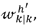

- Then, by combining all the resulting hypotheses, and normalizing the weights

- Furthermore, to keep the number of road model hypotheses manageable, one can employ capping, pruning, and/or merging processes after the update step S103. In more detail, for the merging process, all hypotheses with compatible geometry may be merged. That is, hypotheses that contain the same number of main road lanes and branch lanes, and the same type of branch lanes (on-ramp or exit-ramp - which may be determined from the angle φb ), and all lanes have the same number of segments.
- Executable instructions for performing these functions are, optionally, included in a non-transitory computer-readable storage medium or other computer program product configured for execution by one or more processors.
-
Fig. 5 is a schematic illustration of an ADS-equippedvehicle 1 comprising anapparatus 10 for estimating a road geometry of a road upon which thevehicle 1 is traveling in accordance with some embodiments. The road geometry is described by a filter state that is tracked by a tracking filter, and the filter state comprises a plurality of road model hypotheses. Moreover, each road model hypothesis is associated with a probability and comprises a parametrization of the road describing a geometry of one or more lanes of the road and wherein each lane of each road model hypothesis is associated with a probability of existence. As used herein, a "vehicle" is any form of motorized transport. For example, thevehicle 1 may be any road vehicle such as a car (as illustrated herein), a motorcycle, a (cargo) truck, a bus, etc. - The
apparatus 10 comprisescontrol circuitry 11 and amemory 12. Thecontrol circuitry 11 may physically comprise one single circuitry device. Alternatively, thecontrol circuitry 11 may be distributed over several circuitry devices. As an example, theapparatus 10 may share itscontrol circuitry 11 with other parts of the vehicle 1 (e.g. the ADS 310). Moreover, theapparatus 10 may form a part of theADS 310, i.e. theapparatus 10 may be implemented as a module or feature of the ADS. Thecontrol circuitry 11 may comprise one or more processors, such as a central processing unit (CPU), microcontroller, or microprocessor. The one or more processors may be configured to execute program code stored in thememory 12, in order to carry out various functions and operations of thevehicle 1 in addition to the methods disclosed herein. The processor(s) may be or include any number of hardware components for conducting data or signal processing or for executing computer code stored in thememory 12. Thememory 12 optionally includes high-speed random access memory, such as DRAM, SRAM, DDR RAM, or other random access solid-state memory devices; and optionally includes non-volatile memory, such as one or more magnetic disk storage devices, optical disk storage devices, flash memory devices, or other non-volatile solid-state storage devices. Thememory 12 may include database components, object code components, script components, or any other type of information structure for supporting the various activities of the present description. - In the illustrated example, the
memory 12 further stores mapdata 308. Themap data 308 may for instance be used by theADS 310 of thevehicle 1 in order to perform autonomous functions of thevehicle 1. Themap data 308 may comprise high-definition (HD) map data. It is contemplated that thememory 12, even though illustrated as a separate element from theADS 310, may be provided as an integral element of theADS 310. In other words, according to an exemplary embodiment, any distributed or local memory device may be utilized in the realization of the present inventive concept. Similarly, thecontrol circuitry 11 may be distributed e.g. such that one or more processors of thecontrol circuitry 11 is provided as integral elements of theADS 310 or any other system of thevehicle 1. In other words, according to an exemplary embodiment, any distributed or local control circuitry device may be utilized in the realization of the present inventive concept. TheADS 310 is configured carry out the functions and operations of the autonomous or semi-autonomous functions of thevehicle 1. TheADS 310 can comprise a number of modules, where each module is tasked with different functions of theADS 310. - The
vehicle 1 comprises a number of elements which can be commonly found in autonomous or semi-autonomous vehicles. It will be understood that thevehicle 1 can have any combination of the various elements shown inFig. 5 . Moreover, thevehicle 1 may comprise further elements than those shown inFig. 5 . While the various elements is herein shown as located inside thevehicle 1, one or more of the elements can be located externally to thevehicle 1. For example, the map data may be stored in a remote server and accessed by the various components of thevehicle 1 via thecommunication system 326. - Further, even though the various elements are herein depicted in a certain arrangement, the various elements may also be implemented in different arrangements, as readily understood by the skilled person. It should be further noted that the various elements may be communicatively connected to each other in any suitable way. The
vehicle 1 ofFig. 5 should be seen merely as an illustrative example, as the elements of thevehicle 1 can be realized in several different ways. - The
vehicle 1 further comprises asensor system 320. Thesensor system 320 is configured to acquire sensory data about the vehicle itself, or of its surroundings. Thesensor system 320 may for example comprise a Global Navigation Satellite System (GNSS) module 322 (such as a GPS) configured to collect geographical position data of thevehicle 1. Thesensor system 320 may further comprise one ormore sensors 324. The sensor(s) 324 may be any type of on-board sensors, such as cameras, LIDARs and RADARs, ultrasonic sensors, gyroscopes, accelerometers, odometers etc. It should be appreciated that thesensor system 320 may also provide the possibility to acquire sensory data directly or via dedicated sensor control circuitry in thevehicle 1. - The
vehicle 1 further comprises acommunication system 326. Thecommunication system 326 is configured to communicate with external units, such as other vehicles (i.e. via vehicle-to-vehicle (V2V) communication protocols), remote servers (e.g. cloud servers), databases or other external devices, i.e. vehicle-to-infrastructure (V2I) or vehicle-to-everything (V2X) communication protocols. Thecommunication system 326 may communicate using one or more communication technologies. Thecommunication system 326 may comprise one or more antennas (not shown). Cellular communication technologies may be used for long range communication such as to remote servers or cloud computing systems. In addition, if the cellular communication technology used have low latency, it may also be used for V2V, V2I or V2X communication. Examples of cellular radio technologies are GSM, GPRS, EDGE, LTE, 5G, 5G NR, and so on, also including future cellular solutions. However, in some solutions mid to short range communication technologies may be used such as Wireless Local Area (LAN), e.g. IEEE 802.11 based solutions, for communicating with other vehicles in the vicinity of thevehicle 1 or with local infrastructure elements. ETSI is working on cellular standards for vehicle communication and for instance 5G is considered as a suitable solution due to the low latency and efficient handling of high bandwidths and communication channels. - The
communication system 326 may accordingly provide the possibility to send output to a remote location (e.g. remote operator or control center) and/or to receive input from a remote location by means of the one or more antennas. Moreover, thecommunication system 326 may be further configured to allow the various elements of thevehicle 1 to communicate with each other. As an example, the communication system may provide a local network setup, such as CAN bus, I2C, Ethernet, optical fibers, and so on. Local communication within the vehicle may also be of a wireless type with protocols such as WiFi, LoRa, Zigbee, Bluetooth, or similar mid/short range technologies. - The
vehicle 1 further comprises amaneuvering system 320. Themaneuvering system 328 is configured to control the maneuvering of thevehicle 1. Themaneuvering system 328 comprises asteering module 330 configured to control the heading of thevehicle 1. Themaneuvering system 328 further comprises athrottle module 332 configured to control actuation of the throttle of thevehicle 1. Themaneuvering system 328 further comprises abraking module 334 configured to control actuation of the brakes of thevehicle 1. The various modules of themaneuvering system 328 may also receive manual input from a driver of the vehicle 1 (i.e. from a steering wheel, a gas pedal and a brake pedal respectively). However, themaneuvering system 328 may be communicatively connected to theADS 310 of the vehicle, to receive instructions on how the various modules of themaneuvering system 328 should act. Thus, theADS 310 can control the maneuvering of thevehicle 1, for example via the decision andcontrol module 318. - The
ADS 310 may comprise alocalization module 312 or localization block/system. Thelocalization module 312 is configured to determine and/or monitor a geographical position and heading of thevehicle 1, and may utilize data from thesensor system 320, such as data from theGNSS module 322. Alternatively, or in combination, thelocalization module 312 may utilize data from the one ormore sensors 324. The localization system may alternatively be realized as a Real Time Kinematics (RTK) GPS in order to improve accuracy. - The
ADS 310 may further comprise aperception module 314 or perception block/system 314. Theperception module 314 may refer to any commonly known module and/or functionality, e.g. comprised in one or more electronic control modules and/or nodes of thevehicle 1, adapted and/or configured to interpret sensory data - relevant for driving of the vehicle 1 - to identify e.g. obstacles, vehicle lanes, relevant signage, appropriate navigation paths to be executed by thepath planning module 316 etc. Theperception module 314 may thus be adapted to rely on and obtain inputs from multiple data sources, such as automotive imaging, image processing, computer vision, and/or in-car networking, etc., in combination with sensory data e.g. from thesensor system 320. - The
localization module 312 and/or theperception module 314 may be communicatively connected to thesensor system 320 in order to receive sensory data from thesensor system 320. Thelocalization module 312 and/or theperception module 314 may further transmit control instructions to thesensor system 320. - Accordingly, the
apparatus 10 comprisescontrol circuitry 11 configured to, for each time step out of a plurality of consecutive time steps, predict a filter state by determining a probability of each road model hypothesis based on vehicle motion data and a prior filter state determined at a preceding time step. Thecontrol circuitry 11 is further configured to associate road features obtained from perception data derived from an output of one or more vehicle-mounted sensors with the parametrization of the road of each road model hypothesis of the predicted filter state. Moreover, thecontrol circuitry 11 is configured to determine an existence probability for each lane of each road model hypothesis based on a prior existence probability for each corresponding lane determined at the preceding time step and the road feature association. The control circuitry is further configured to determine a probability of each road model hypothesis of the plurality of road model hypotheses based on the prior filter state determined at the preceding time step and the determined existence probability of each lane of that road model hypothesis, select the road model hypothesis associated with the highest probability based on the determined probability of each road model hypothesis, and output a road model based on the parametrization of the road of the selected road model hypothesis. - The present invention has been presented above with reference to specific embodiments. However, other embodiments than the above described are possible and within the scope of the invention. Different method steps than those described above, performing the method by hardware or software, may be provided within the scope of the invention. Thus, according to an exemplary embodiment, there is provided a non-transitory computer-readable storage medium storing one or more programs configured to be executed by one or more processors of a processing device, the one or more programs comprising instructions for performing the method according to any one of the above-discussed embodiments. Alternatively, according to another exemplary embodiment a cloud computing system can be configured to perform any of the methods presented herein. The cloud computing system may comprise distributed cloud computing resources that jointly perform the methods presented herein under control of one or more computer program products.
- Generally speaking, a computer-accessible medium may include any tangible or non-transitory storage media or memory media such as electronic, magnetic, or optical media-e.g., disk or CD/DVD-ROM coupled to computer system via bus. The terms "tangible" and "non-transitory," as used herein, are intended to describe a computer-readable storage medium (or "memory") excluding propagating electromagnetic signals, but are not intended to otherwise limit the type of physical computer-readable storage device that is encompassed by the phrase computer-readable medium or memory. For instance, the terms "non-transitory computer-readable medium" or "tangible memory" are intended to encompass types of storage devices that do not necessarily store information permanently, including for example, random access memory (RAM). Program instructions and data stored on a tangible computer-accessible storage medium in non-transitory form may further be transmitted by transmission media or signals such as electrical, electromagnetic, or digital signals, which may be conveyed via a communication medium such as a network and/or a wireless link.
- The processor(s) 11 (associated with the apparatus 10) may be or include any number of hardware components for conducting data or signal processing or for executing computer code stored in
memory 12. Thedevice 10 has an associatedmemory 12, and thememory 12 may be one or more devices for storing data and/or computer code for completing or facilitating the various methods described in the present description. The memory may include volatile memory or non-volatile memory. Thememory 12 may include database components, object code components, script components, or any other type of information structure for supporting the various activities of the present description. According to an exemplary embodiment, any distributed or local memory device may be utilized with the systems and methods of this description. According to an exemplary embodiment thememory 12 is communicably connected to the processor 11 (e.g., via a circuit or any other wired, wireless, or network connection) and includes computer code for executing one or more processes described herein. - Accordingly, it should be understood that parts of the described solution may be implemented either in the
vehicle 1, in a system located external thevehicle 1, or in a combination of internal and external the vehicle; for instance in a server in communication with the vehicle, a so called cloud solution. The different features and steps of the embodiments may be combined in other combinations than those described. - It should be noted that any reference signs do not limit the scope of the claims, that the invention may be at least in part implemented by means of both hardware and software, and that several "means" or "units" may be represented by the same item of hardware.
- Although the figures may show a specific order of method steps, the order of the steps may differ from what is depicted. In addition, two or more steps may be performed concurrently or with partial concurrence. Such variation will depend on the software and hardware systems chosen and on designer choice. All such variations are within the scope of the invention. Likewise, software implementations could be accomplished with standard programming techniques with rule-based logic and other logic to accomplish the various predicting steps, associating steps, determining steps, selecting steps, adding steps, removing steps, tagging steps and outputting steps. The above mentioned and described embodiments are only given as examples and should not be limiting to the present invention. Other solutions, uses, objectives, and functions within the scope of the invention as claimed in the below described patent claims should be apparent for the person skilled in the art.
Claims (15)
- A computer-implemented method (S100) for estimating a road geometry of a road upon which a vehicle is traveling, wherein the road geometry is described by a filter state that is tracked by a tracking filter, the filter state comprising a plurality of road model hypotheses, wherein each road model hypothesis is associated with a probability and comprises a parametrization of the road describing a geometry of one or more lanes of the road and wherein each lane of each road model hypothesis is associated with a probability of existence, the method comprising:
for each time step out of a plurality of consecutive time steps:predicting (S101) a filter state by determining a probability density of each road model hypothesis based on vehicle motion data and a prior filter state determined at a preceding time step;associating (S102) road features obtained from perception data derived from an output of one or more vehicle-mounted sensors with the parametrization of the road of each road model hypothesis of the predicted filter state;determining (S104) an existence probability for each lane of each road model hypothesis based on a prior existence probability for each corresponding lane determined at the preceding time step and the road feature association;determining (S105) a probability of each road model hypothesis of the plurality of road model hypotheses based on the prior filter state determined at the preceding time step and the determined existence probability of each lane of that road model hypothesis;selecting (S106) the road model hypothesis associated with the highest probability based on the determined probability of each road model hypothesis; andoutputting (S107) a road model based on the parametrization of the road of the selected road model hypothesis. - The method (S100) according to claim 1, wherein the parametrization of the road comprises a lane center parametrization for each lane of the road and a width parametrization for each lane of the road.
- The method (S100) according to claim 1 or 2, wherein the parametrization of the road comprises:an ego-lane center curvature (k0) of each segment of an ego-lane of a main road,a width (ω 01) of each segment of the ego-lane,a width (ω 02) of each segment of one or more adjacent main road lanes of the main road, anda pose (x, y, φ 0) of the vehicle relative to a starting point of the ego-lane center.
- The method (S100) according to claim 3, wherein the parametrization of the road comprises:a classification of each lane as a main road lane or a branch lane;a branch-lane distance (a 1), of each branch lane, from a starting point of a connecting main road lane center to a connection point of the branch lane to the connecting main road lane center,a branch-lane angle (φ 1), of each branch lane, relative to the connecting main-road lane center at the connecting point,a branch-lane curvature (k 1) of each segment of the one or more branch lanes, anda branch-lane width (ω 1) of each segment of the one or more branch lanes.
- The method (S100) according to any one of claims 1-4, further comprising:
for each time step out of the plurality of consecutive time steps:adding (S108) one or more main road lanes and/or one or more branch lanes to each road model hypothesis of the predicted filter state;removing (S110) any added main road lanes and branch lanes that have no road feature association. - The method (S100) according to claim 5, further comprising:
for each time step out of the plurality of consecutive time steps:
tagging (S109) the added one or more main road lanes and/or one or more branch lanes. - The method (S100) according to any one of claims 1-6, wherein the road features obtained from perception data derived from an output of one or more vehicle-mounted sensors comprises lane marking detections obtained from a lane tracking algorithm configured to output coordinates of lane markers depicted in images output from a vehicle-mounted camera.
- The method (S100) according to any one of claims 1-7, wherein the vehicle motion data comprises a vehicle speed.
- The method (S100) according to any one of claims 1-8, further comprising:
for each time step out of the plurality of consecutive time steps:
forming (S111) the road model based on the parametrization of the road of the selected road model hypothesis by converting the road model parametrization to polylines describing lane centers of the lanes of the road. - The method (S100) according to any one of claims 1-9, wherein the road model is output to a path planning function of an automated driving system of the vehicle, the path planning function being configured to generate paths for the vehicle to execute.
- A computer program product comprising instructions which, when the program is executed by a computing device of a vehicle, causes the computing device to carry out the method (S100) according to any one of claims 1-10.
- A computer-readable storage medium comprising instructions which, when executed by a computing device of a vehicle, causes the computing device to carry out the method (S100) according to any one of claims 1-10.
- An apparatus (10) for estimating a road geometry of a road upon which a vehicle (1) is traveling, wherein the road geometry is described by a filter state that is tracked by a tracking filter, the filter state comprising a plurality of road model hypotheses, wherein each road model hypothesis is associated with a probability and comprises a parametrization of the road describing a geometry of one or more lanes of the road and wherein each lane of each road model hypothesis is associated with a probability of existence, the apparatus comprising control circuitry (11) configured to:
for each time step out of a plurality of consecutive time steps:predict a filter state by determining a probability of each road model hypothesis based on vehicle motion data and a prior filter state determined at a preceding time step;associate road features obtained from perception data derived from an output of one or more vehicle-mounted sensors with the parametrization of the road of each road model hypothesis of the predicted filter state;determine an existence probability for each lane of each road model hypothesis based on a prior existence probability for each corresponding lane determined at the preceding time step and the road feature association;determine a probability of each road model hypothesis of the plurality of road model hypotheses based on the prior filter state determined at the preceding time step and the determined existence probability of each lane of that road model hypothesis;select the road model hypothesis associated with the highest probability based on the determined probability of each road model hypothesis; andoutput a road model based on the parametrization of the road of the selected road model hypothesis. - The apparatus (10) according to claim 13, wherein the road model is output to a path planning function of an automated driving system of the vehicle, the path planning function (316) being configured to generate paths for the vehicle (1) to execute.
- A vehicle (1) comprising an apparatus (10) according to any one of claims 13-14.
Priority Applications (3)
| Application Number | Priority Date | Filing Date | Title |
|---|---|---|---|
| EP23178905.8A EP4478304A1 (en) | 2023-06-13 | 2023-06-13 | Model-based road estimation |
| US18/739,846 US20240425056A1 (en) | 2023-06-13 | 2024-06-11 | Model-based road estimation |
| CN202410763463.7A CN119131718A (en) | 2023-06-13 | 2024-06-13 | Model-based road estimation |
Applications Claiming Priority (1)
| Application Number | Priority Date | Filing Date | Title |
|---|---|---|---|
| EP23178905.8A EP4478304A1 (en) | 2023-06-13 | 2023-06-13 | Model-based road estimation |
Publications (1)
| Publication Number | Publication Date |
|---|---|
| EP4478304A1 true EP4478304A1 (en) | 2024-12-18 |
Family
ID=86764367
Family Applications (1)
| Application Number | Title | Priority Date | Filing Date |
|---|---|---|---|
| EP23178905.8A Pending EP4478304A1 (en) | 2023-06-13 | 2023-06-13 | Model-based road estimation |
Country Status (3)
| Country | Link |
|---|---|
| US (1) | US20240425056A1 (en) |
| EP (1) | EP4478304A1 (en) |
| CN (1) | CN119131718A (en) |
Families Citing this family (1)
| Publication number | Priority date | Publication date | Assignee | Title |
|---|---|---|---|---|
| US20250277664A1 (en) * | 2024-02-29 | 2025-09-04 | Zoox, Inc. | Automated Mapping for Autonomous Vehicle Navigation |
Citations (2)
| Publication number | Priority date | Publication date | Assignee | Title |
|---|---|---|---|---|
| US6718259B1 (en) * | 2002-10-02 | 2004-04-06 | Hrl Laboratories, Llc | Adaptive Kalman filter method for accurate estimation of forward path geometry of an automobile |
| US20120185167A1 (en) * | 2009-07-29 | 2012-07-19 | Hitachi Automotive Systems Ltd | Road Shape Recognition Device |
Family Cites Families (106)
| Publication number | Priority date | Publication date | Assignee | Title |
|---|---|---|---|---|
| US5646843A (en) * | 1990-02-05 | 1997-07-08 | Caterpillar Inc. | Apparatus and method for surface based vehicle control system |
| US6131072A (en) * | 1998-02-03 | 2000-10-10 | Pe Applied Biosystems, A Division Of Perkin-Elmer | Lane tracking system and method |
| US6393362B1 (en) * | 2000-03-07 | 2002-05-21 | Modular Mining Systems, Inc. | Dynamic safety envelope for autonomous-vehicle collision avoidance system |
| JP3733875B2 (en) * | 2000-09-29 | 2006-01-11 | 日産自動車株式会社 | Road white line recognition device |
| JP3521860B2 (en) * | 2000-10-02 | 2004-04-26 | 日産自動車株式会社 | Vehicle travel path recognition device |
| JP3780848B2 (en) * | 2000-12-27 | 2006-05-31 | 日産自動車株式会社 | Vehicle traveling path recognition device |
| JP3729095B2 (en) * | 2001-06-29 | 2005-12-21 | 日産自動車株式会社 | Traveling path detection device |
| US6751547B2 (en) * | 2001-11-26 | 2004-06-15 | Hrl Laboratories, Llc | Method and apparatus for estimation of forward path geometry of a vehicle based on a two-clothoid road model |
| CN100365430C (en) * | 2002-07-15 | 2008-01-30 | 汽车系统实验室公司 | Road Curvature Estimation and Vehicle Object State Estimation System |
| US7136753B2 (en) * | 2002-12-05 | 2006-11-14 | Denso Corporation | Object recognition apparatus for vehicle, inter-vehicle control apparatus, and distance measurement apparatus |
| FR2907582A1 (en) * | 2006-10-23 | 2008-04-25 | Nodbox Sarl | Localized and adaptive road algorithm determining method for e.g. management of road, involves determining dynamic road information by calculation unit for managing roads and cartographies of navigation |
| US20080243378A1 (en) * | 2007-02-21 | 2008-10-02 | Tele Atlas North America, Inc. | System and method for vehicle navigation and piloting including absolute and relative coordinates |
| US8612136B2 (en) * | 2008-08-27 | 2013-12-17 | Waze Mobile Ltd. | System and method for road map creation |
| US8704653B2 (en) * | 2009-04-02 | 2014-04-22 | GM Global Technology Operations LLC | Enhanced road vision on full windshield head-up display |
| US8912978B2 (en) * | 2009-04-02 | 2014-12-16 | GM Global Technology Operations LLC | Dynamic vehicle system information on full windshield head-up display |
| US8629784B2 (en) * | 2009-04-02 | 2014-01-14 | GM Global Technology Operations LLC | Peripheral salient feature enhancement on full-windshield head-up display |
| JP5258859B2 (en) * | 2010-09-24 | 2013-08-07 | 株式会社豊田中央研究所 | Runway estimation apparatus and program |
| DE102012204441A1 (en) * | 2011-03-21 | 2012-09-27 | Denso Corporation | Method and device for detecting a course of a road for vehicles |
| US8755966B2 (en) * | 2012-04-03 | 2014-06-17 | Caterpillar Inc. | System and method for controlling autonomous machine within lane boundaries during position uncertainty |
| US20130278441A1 (en) * | 2012-04-24 | 2013-10-24 | Zetta Research and Development, LLC - ForC Series | Vehicle proxying |
| US9253753B2 (en) * | 2012-04-24 | 2016-02-02 | Zetta Research And Development Llc-Forc Series | Vehicle-to-vehicle safety transceiver using time slots |
| JP5880703B2 (en) * | 2012-06-14 | 2016-03-09 | トヨタ自動車株式会社 | Lane marking indicator, driving support system |
| JP5829980B2 (en) * | 2012-06-19 | 2015-12-09 | トヨタ自動車株式会社 | Roadside detection device |
| US9460624B2 (en) * | 2014-05-06 | 2016-10-04 | Toyota Motor Engineering & Manufacturing North America, Inc. | Method and apparatus for determining lane identification in a roadway |
| US10438073B2 (en) * | 2014-10-28 | 2019-10-08 | Trw Automotive U.S. Llc | Augmented lane detection using kinematic data |
| US9530062B2 (en) * | 2014-12-23 | 2016-12-27 | Volkswagen Ag | Fused raised pavement marker detection for autonomous driving using lidar and camera |
| JP6363519B2 (en) * | 2015-01-21 | 2018-07-25 | 株式会社デンソー | Vehicle control device |
| CN111380545B (en) * | 2015-02-10 | 2024-11-12 | 御眼视觉技术有限公司 | Method, server, autonomous vehicle and medium for autonomous vehicle navigation |
| US9483700B1 (en) * | 2015-05-13 | 2016-11-01 | Honda Motor Co., Ltd. | System and method for lane vehicle localization with lane marking detection and likelihood scoring |
| EP3098753A1 (en) * | 2015-05-28 | 2016-11-30 | Tata Consultancy Services Limited | Lane detection |
| DE112015006622B4 (en) * | 2015-06-15 | 2025-02-06 | Mitsubishi Electric Corporation | lane determination device and lane determination method |
| DE102015214338A1 (en) * | 2015-07-29 | 2017-02-02 | Volkswagen Aktiengesellschaft | Determining an arrangement information for a vehicle |
| CN105046235B (en) * | 2015-08-03 | 2018-09-07 | 百度在线网络技术(北京)有限公司 | The identification modeling method and device of lane line, recognition methods and device |
| US20190016339A1 (en) * | 2016-02-16 | 2019-01-17 | Honda Motor Co., Ltd. | Vehicle control device, vehicle control method, and vehicle control program |
| DE102016210027A1 (en) * | 2016-06-07 | 2017-12-07 | Robert Bosch Gmbh | Method Device and system for wrong driver identification |
| CN109416256B (en) * | 2016-07-05 | 2022-03-22 | 三菱电机株式会社 | Travel lane estimation system |
| US10248124B2 (en) * | 2016-07-21 | 2019-04-02 | Mobileye Vision Technologies, Inc. | Localizing vehicle navigation using lane measurements |
| US11248925B2 (en) * | 2016-07-28 | 2022-02-15 | Toyota Motor Engineering & Manufacturing North America, Inc. | Augmented road line detection and display system |
| US10175059B2 (en) * | 2016-08-30 | 2019-01-08 | Here Global B.V. | Method, apparatus and computer program product for a navigation system user interface |
| US10330479B2 (en) * | 2016-09-20 | 2019-06-25 | Trimble Inc. | Vehicle navigation by dead reckoning and GNSS-aided map-matching |
| KR102766548B1 (en) * | 2016-11-07 | 2025-02-12 | 삼성전자주식회사 | Generating method and apparatus of 3d lane model |
| JP6613223B2 (en) * | 2016-11-17 | 2019-11-27 | 株式会社デンソー | Travel control device |
| DE102017209346A1 (en) * | 2017-06-01 | 2019-01-10 | Robert Bosch Gmbh | Method and device for creating a lane-accurate road map |
| US10446022B2 (en) * | 2017-06-09 | 2019-10-15 | Here Global B.V. | Reversible lane active direction detection based on GNSS probe data |
| US10296795B2 (en) * | 2017-06-26 | 2019-05-21 | Here Global B.V. | Method, apparatus, and system for estimating a quality of lane features of a roadway |
| JP6522068B2 (en) * | 2017-08-25 | 2019-05-29 | 三菱電機株式会社 | Road shape prediction device, other vehicle course prediction device, and driving assistance device |
| WO2019071212A1 (en) * | 2017-10-06 | 2019-04-11 | Netradyne Inc. | System and method of determining a curve |
| CA3079656C (en) * | 2017-10-24 | 2021-11-23 | Nissan North America, Inc. | Localization determination for vehicle operation |
| WO2019094843A1 (en) * | 2017-11-10 | 2019-05-16 | Nvidia Corporation | Systems and methods for safe and reliable autonomous vehicles |
| US10657390B2 (en) * | 2017-11-27 | 2020-05-19 | Tusimple, Inc. | System and method for large-scale lane marking detection using multimodal sensor data |
| JP2019191653A (en) * | 2018-04-18 | 2019-10-31 | アイシン・エィ・ダブリュ株式会社 | Map information update system and map information update program |
| US10852443B2 (en) * | 2018-05-10 | 2020-12-01 | Here Global B.V. | Algorithm and architecture for map-matching streaming probe data |
| CN109147368A (en) * | 2018-08-22 | 2019-01-04 | 北京市商汤科技开发有限公司 | Intelligent driving control method device and electronic equipment based on lane line |
| JP7087896B2 (en) * | 2018-10-01 | 2022-06-21 | 株式会社Soken | Driving lane estimation device, driving lane estimation method, and control program |
| US11120277B2 (en) * | 2018-10-10 | 2021-09-14 | Denso Corporation | Apparatus and method for recognizing road shapes |
| KR102633140B1 (en) * | 2018-10-23 | 2024-02-05 | 삼성전자주식회사 | Method and apparatus of determining driving information |
| US10989555B2 (en) * | 2018-11-05 | 2021-04-27 | Robert Bosch Gmbh | System and method for automated semantic map generation |
| US11577750B2 (en) * | 2018-11-08 | 2023-02-14 | Bayerische Motoren Werke Aktiengesellschaft | Method and apparatus for determining a vehicle comfort metric for a prediction of a driving maneuver of a target vehicle |
| US10839524B2 (en) * | 2018-11-27 | 2020-11-17 | GM Global Technology Operations LLC | Systems and methods for applying maps to improve object tracking, lane-assignment and classification |
| CN109783588A (en) * | 2018-12-10 | 2019-05-21 | 北京百度网讯科技有限公司 | Error message detection method, device, equipment, vehicle and the storage medium of map |
| US11087173B2 (en) * | 2018-12-27 | 2021-08-10 | Beijing Didi Infinity Technology And Development Co., Ltd. | Using image pre-processing to generate a machine learning model |
| JP7077967B2 (en) * | 2019-01-10 | 2022-05-31 | 株式会社Soken | Driving lane estimation device, driving lane estimation method, and control program |
| US11093761B2 (en) * | 2019-03-06 | 2021-08-17 | GM Global Technology Operations LLC | Lane position sensing and tracking in a vehicle |
| WO2020240274A1 (en) * | 2019-05-28 | 2020-12-03 | Mobileye Vision Technologies Ltd. | Systems and methods for vehicle navigation |
| EP3786012B1 (en) * | 2019-08-29 | 2024-10-23 | Zenuity AB | Lane keeping for autonomous vehicles |
| CN112885074B (en) * | 2019-11-30 | 2023-01-13 | 华为技术有限公司 | Road information detection method and device |
| JP7359715B2 (en) * | 2020-02-14 | 2023-10-11 | 株式会社Soken | Road shape estimation device |
| US11170649B2 (en) * | 2020-02-26 | 2021-11-09 | International Business Machines Corporation | Integrated collision avoidance and road safety management system |
| US11604075B2 (en) * | 2020-03-30 | 2023-03-14 | Woven Planet North America, Inc. | Systems and methods for deriving planned paths for vehicles using path priors |
| WO2021208110A1 (en) * | 2020-04-18 | 2021-10-21 | 华为技术有限公司 | Method for determining lane line recognition abnormal event, and lane line recognition apparatus and system |
| CN113538923A (en) * | 2020-04-20 | 2021-10-22 | 深圳富泰宏精密工业有限公司 | Warning method for vehicle lane change and vehicle-mounted device |
| CN113873426B (en) * | 2020-06-30 | 2025-01-24 | 罗伯特·博世有限公司 | System, control unit and method for determining geo-fence events for a vehicle |
| US11807272B2 (en) * | 2020-07-28 | 2023-11-07 | Toyota Research Institute, Inc. | Systems and methods for multiple algorithm selection |
| US11756313B2 (en) * | 2020-09-29 | 2023-09-12 | Aptiv Technologies Limited | Road-perception system configured to estimate a belief and plausibility of lanes in a road model |
| KR20220049640A (en) * | 2020-10-14 | 2022-04-22 | 현대자동차주식회사 | Vehicle and method of driving control for the same |
| US11721111B2 (en) * | 2020-10-16 | 2023-08-08 | Verizon Connect Development Limited | Systems and methods for detecting objects in an image of an environment |
| US11577732B2 (en) * | 2020-10-28 | 2023-02-14 | Argo AI, LLC | Methods and systems for tracking a mover's lane over time |
| US11873011B2 (en) * | 2020-10-29 | 2024-01-16 | Waymo Llc | Labeling lane segments for behavior prediction for agents in an environment |
| CN112529254B (en) * | 2020-11-19 | 2022-11-25 | 歌尔股份有限公司 | Path planning method and device and electronic equipment |
| US11657625B2 (en) * | 2020-12-18 | 2023-05-23 | Toyota Research Institue, Inc. | System and method for determining implicit lane boundaries |
| JP2022139009A (en) * | 2021-03-11 | 2022-09-26 | 本田技研工業株式会社 | Drive support device, drive support method, and program |
| CN112884837B (en) * | 2021-03-16 | 2023-06-20 | 百度在线网络技术(北京)有限公司 | Road positioning method, device, equipment and storage medium |
| US11661109B2 (en) * | 2021-04-22 | 2023-05-30 | GM Global Technology Operations LLC | Motor vehicle with turn signal-based lane localization |
| CN115339458A (en) * | 2021-04-28 | 2022-11-15 | 华为技术有限公司 | Pavement type identification method and device and vehicle |
| US20230009269A1 (en) * | 2021-07-07 | 2023-01-12 | Aptiv Technologies Limited | Lidar enhanced polynomial generation for lane centering |
| CN113386771A (en) * | 2021-07-30 | 2021-09-14 | 蔚来汽车科技(安徽)有限公司 | Road model generation method and equipment |
| CN113739811B (en) * | 2021-09-03 | 2024-06-11 | 阿波罗智能技术(北京)有限公司 | Key point detection model training and high-precision map lane line generation method and equipment |
| US12214785B2 (en) * | 2021-09-13 | 2025-02-04 | Aptiv Technologies AG | Vehicle localization to map data |
| CN114719840B (en) * | 2022-04-07 | 2025-03-11 | 岚图汽车科技有限公司 | A vehicle intelligent driving guarantee method and system based on road feature fusion |
| WO2023205444A1 (en) * | 2022-04-22 | 2023-10-26 | Velo.Ai, Inc. | Artificially intelligent mobility safety system |
| GB2618616A (en) * | 2022-05-13 | 2023-11-15 | Aptiv Tech Ltd | Vehicle lane determination method, computer program product, and apparatus |
| EP4279869B1 (en) * | 2022-05-16 | 2024-10-30 | Zenseact AB | Determining a state of a vehicle on a road |
| US11551459B1 (en) * | 2022-06-27 | 2023-01-10 | Plusai, Inc. | Ambiguous lane detection event miner |
| CN117709040A (en) * | 2022-09-06 | 2024-03-15 | 腾讯科技(深圳)有限公司 | Data processing method, device, equipment and computer readable storage medium |
| DE102022212897A1 (en) * | 2022-11-30 | 2024-06-06 | Zf Friedrichshafen Ag | Method, control device and computer program for determining a probability with which an autonomous motor vehicle is located in a lane of a roadway, and computer-readable storage medium |
| US20240185617A1 (en) * | 2022-12-02 | 2024-06-06 | Ford Global Technologies, Llc | Method to Detect Lane Segments for Creating High Definition Maps |
| US12509074B2 (en) * | 2023-03-23 | 2025-12-30 | Torc Robotics, Inc. | Systems and methods for high precision lane-keeping by autonomous vehicles |
| EP4439012A1 (en) * | 2023-03-29 | 2024-10-02 | Zenseact AB | Operational design domain management for vehicles having automated driving systems |
| EP4439014A1 (en) * | 2023-03-30 | 2024-10-02 | Zenseact AB | Vehicle localization |
| US12570317B2 (en) * | 2023-06-12 | 2026-03-10 | GM Global Technology Operations LLC | Vehicle systems and methods for autonomous operation using unclassified hazard detection |
| US20250044118A1 (en) * | 2023-07-31 | 2025-02-06 | GM Global Technology Operations LLC | Dynamically updating vehicle road maps |
| EP4530881A1 (en) * | 2023-09-26 | 2025-04-02 | Robert Bosch GmbH | Device and method for driving assisting or autonomous driving functions |
| CN117671410A (en) * | 2023-10-20 | 2024-03-08 | 北京百度网讯科技有限公司 | Training methods and map generation methods for large map generation models |
| US20250137809A1 (en) * | 2023-10-31 | 2025-05-01 | Toyota Jidosha Kabushiki Kaisha | Drivable surface and lane group estimation |
| EP4645259A1 (en) * | 2024-04-30 | 2025-11-05 | Zenseact AB | In-vehicle perception performance evaluation |
| US20250378569A1 (en) * | 2024-06-10 | 2025-12-11 | Qualcomm Incorporated | Determining positions of objects based on images and ground-plane models |
-
2023
- 2023-06-13 EP EP23178905.8A patent/EP4478304A1/en active Pending
-
2024
- 2024-06-11 US US18/739,846 patent/US20240425056A1/en active Pending
- 2024-06-13 CN CN202410763463.7A patent/CN119131718A/en active Pending
Patent Citations (2)
| Publication number | Priority date | Publication date | Assignee | Title |
|---|---|---|---|---|
| US6718259B1 (en) * | 2002-10-02 | 2004-04-06 | Hrl Laboratories, Llc | Adaptive Kalman filter method for accurate estimation of forward path geometry of an automobile |
| US20120185167A1 (en) * | 2009-07-29 | 2012-07-19 | Hitachi Automotive Systems Ltd | Road Shape Recognition Device |
Also Published As
| Publication number | Publication date |
|---|---|
| US20240425056A1 (en) | 2024-12-26 |
| CN119131718A (en) | 2024-12-13 |
Similar Documents
| Publication | Publication Date | Title |
|---|---|---|
| EP3745158B1 (en) | Methods and systems for computer-based determining of presence of dynamic objects | |
| US10604156B2 (en) | System and method for adjusting a road boundary | |
| US20200333784A1 (en) | Safety and comfort constraints for navigation | |
| EP3644294B1 (en) | Vehicle information storage method, vehicle travel control method, and vehicle information storage device | |
| US9283967B2 (en) | Accurate curvature estimation algorithm for path planning of autonomous driving vehicle | |
| US11521329B2 (en) | Updated point cloud registration pipeline based on ADMM algorithm for autonomous vehicles | |
| US12403933B2 (en) | Determining a state of a vehicle on a road | |
| EP4439012A1 (en) | Operational design domain management for vehicles having automated driving systems | |
| DE102023134220A1 (en) | Systems and methods for child track assignment with radar detection for speed transmission | |
| EP4138048B1 (en) | Training of 3d lane detection models for automotive applications | |
| US20240425056A1 (en) | Model-based road estimation | |
| US12227195B2 (en) | Hypothesis inference for vehicles | |
| EP4261738B1 (en) | Multi-target lane tracking | |
| US11983918B2 (en) | Platform for perception system development for automated driving system | |
| US20200125111A1 (en) | Moving body control apparatus | |
| US20240328793A1 (en) | Vehicle localization | |
| Yoon et al. | High-definition map based motion planning, and control for urban autonomous driving | |
| US20240265713A1 (en) | Drive device, vehicle, and method for automated driving and/or assisted driving | |
| US11544899B2 (en) | System and method for generating terrain maps | |
| US20250155254A1 (en) | Localization with point to line matching | |
| US20240246550A1 (en) | System and method for minimizing aliasing in sample-based estimators | |
| EP4266261A1 (en) | 3d road surface estimation for automated driving systems |
Legal Events
| Date | Code | Title | Description |
|---|---|---|---|
| PUAI | Public reference made under article 153(3) epc to a published international application that has entered the european phase |
Free format text: ORIGINAL CODE: 0009012 |
|
| STAA | Information on the status of an ep patent application or granted ep patent |
Free format text: STATUS: THE APPLICATION HAS BEEN PUBLISHED |
|
| AK | Designated contracting states |
Kind code of ref document: A1 Designated state(s): AL AT BE BG CH CY CZ DE DK EE ES FI FR GB GR HR HU IE IS IT LI LT LU LV MC ME MK MT NL NO PL PT RO RS SE SI SK SM TR |
|
| STAA | Information on the status of an ep patent application or granted ep patent |
Free format text: STATUS: REQUEST FOR EXAMINATION WAS MADE |
|
| 17P | Request for examination filed |
Effective date: 20250609 |