EP4478084A1 - Measurement apparatus - Google Patents
Measurement apparatus Download PDFInfo
- Publication number
- EP4478084A1 EP4478084A1 EP23752832.8A EP23752832A EP4478084A1 EP 4478084 A1 EP4478084 A1 EP 4478084A1 EP 23752832 A EP23752832 A EP 23752832A EP 4478084 A1 EP4478084 A1 EP 4478084A1
- Authority
- EP
- European Patent Office
- Prior art keywords
- light
- light receiving
- unit
- measurement
- receiving unit
- Prior art date
- Legal status (The legal status is an assumption and is not a legal conclusion. Google has not performed a legal analysis and makes no representation as to the accuracy of the status listed.)
- Withdrawn
Links
Images



Classifications
-
- G—PHYSICS
- G01—MEASURING; TESTING
- G01S—RADIO DIRECTION-FINDING; RADIO NAVIGATION; DETERMINING DISTANCE OR VELOCITY BY USE OF RADIO WAVES; LOCATING OR PRESENCE-DETECTING BY USE OF THE REFLECTION OR RERADIATION OF RADIO WAVES; ANALOGOUS ARRANGEMENTS USING OTHER WAVES
- G01S7/00—Details of systems according to groups G01S13/00, G01S15/00, G01S17/00
- G01S7/48—Details of systems according to groups G01S13/00, G01S15/00, G01S17/00 of systems according to group G01S17/00
- G01S7/483—Details of pulse systems
- G01S7/486—Receivers
- G01S7/487—Extracting wanted echo signals, e.g. pulse detection
- G01S7/4873—Extracting wanted echo signals, e.g. pulse detection by deriving and controlling a threshold value
-
- G—PHYSICS
- G01—MEASURING; TESTING
- G01S—RADIO DIRECTION-FINDING; RADIO NAVIGATION; DETERMINING DISTANCE OR VELOCITY BY USE OF RADIO WAVES; LOCATING OR PRESENCE-DETECTING BY USE OF THE REFLECTION OR RERADIATION OF RADIO WAVES; ANALOGOUS ARRANGEMENTS USING OTHER WAVES
- G01S17/00—Systems using the reflection or reradiation of electromagnetic waves other than radio waves, e.g. lidar systems
- G01S17/02—Systems using the reflection of electromagnetic waves other than radio waves
- G01S17/06—Systems determining position data of a target
- G01S17/08—Systems determining position data of a target for measuring distance only
- G01S17/10—Systems determining position data of a target for measuring distance only using transmission of interrupted, pulse-modulated waves
-
- G—PHYSICS
- G01—MEASURING; TESTING
- G01S—RADIO DIRECTION-FINDING; RADIO NAVIGATION; DETERMINING DISTANCE OR VELOCITY BY USE OF RADIO WAVES; LOCATING OR PRESENCE-DETECTING BY USE OF THE REFLECTION OR RERADIATION OF RADIO WAVES; ANALOGOUS ARRANGEMENTS USING OTHER WAVES
- G01S17/00—Systems using the reflection or reradiation of electromagnetic waves other than radio waves, e.g. lidar systems
- G01S17/88—Lidar systems specially adapted for specific applications
- G01S17/89—Lidar systems specially adapted for specific applications for mapping or imaging
- G01S17/894—Three-dimensional [3D] imaging with simultaneous measurement of time-of-flight at a two-dimensional [2D] array of receiver pixels, e.g. time-of-flight cameras or flash lidar
-
- G—PHYSICS
- G01—MEASURING; TESTING
- G01S—RADIO DIRECTION-FINDING; RADIO NAVIGATION; DETERMINING DISTANCE OR VELOCITY BY USE OF RADIO WAVES; LOCATING OR PRESENCE-DETECTING BY USE OF THE REFLECTION OR RERADIATION OF RADIO WAVES; ANALOGOUS ARRANGEMENTS USING OTHER WAVES
- G01S17/00—Systems using the reflection or reradiation of electromagnetic waves other than radio waves, e.g. lidar systems
- G01S17/88—Lidar systems specially adapted for specific applications
- G01S17/93—Lidar systems specially adapted for specific applications for anti-collision purposes
- G01S17/931—Lidar systems specially adapted for specific applications for anti-collision purposes of land vehicles
-
- G—PHYSICS
- G01—MEASURING; TESTING
- G01S—RADIO DIRECTION-FINDING; RADIO NAVIGATION; DETERMINING DISTANCE OR VELOCITY BY USE OF RADIO WAVES; LOCATING OR PRESENCE-DETECTING BY USE OF THE REFLECTION OR RERADIATION OF RADIO WAVES; ANALOGOUS ARRANGEMENTS USING OTHER WAVES
- G01S7/00—Details of systems according to groups G01S13/00, G01S15/00, G01S17/00
- G01S7/48—Details of systems according to groups G01S13/00, G01S15/00, G01S17/00 of systems according to group G01S17/00
- G01S7/483—Details of pulse systems
- G01S7/484—Transmitters
-
- G—PHYSICS
- G01—MEASURING; TESTING
- G01S—RADIO DIRECTION-FINDING; RADIO NAVIGATION; DETERMINING DISTANCE OR VELOCITY BY USE OF RADIO WAVES; LOCATING OR PRESENCE-DETECTING BY USE OF THE REFLECTION OR RERADIATION OF RADIO WAVES; ANALOGOUS ARRANGEMENTS USING OTHER WAVES
- G01S7/00—Details of systems according to groups G01S13/00, G01S15/00, G01S17/00
- G01S7/48—Details of systems according to groups G01S13/00, G01S15/00, G01S17/00 of systems according to group G01S17/00
- G01S7/483—Details of pulse systems
- G01S7/486—Receivers
- G01S7/4861—Circuits for detection, sampling, integration or read-out
- G01S7/4863—Detector arrays, e.g. charge-transfer gates
-
- G—PHYSICS
- G01—MEASURING; TESTING
- G01S—RADIO DIRECTION-FINDING; RADIO NAVIGATION; DETERMINING DISTANCE OR VELOCITY BY USE OF RADIO WAVES; LOCATING OR PRESENCE-DETECTING BY USE OF THE REFLECTION OR RERADIATION OF RADIO WAVES; ANALOGOUS ARRANGEMENTS USING OTHER WAVES
- G01S7/00—Details of systems according to groups G01S13/00, G01S15/00, G01S17/00
- G01S7/48—Details of systems according to groups G01S13/00, G01S15/00, G01S17/00 of systems according to group G01S17/00
- G01S7/483—Details of pulse systems
- G01S7/486—Receivers
- G01S7/4865—Time delay measurement, e.g. time-of-flight measurement, time of arrival measurement or determining the exact position of a peak
- G01S7/4866—Time delay measurement, e.g. time-of-flight measurement, time of arrival measurement or determining the exact position of a peak by fitting a model or function to the received signal
-
- G—PHYSICS
- G01—MEASURING; TESTING
- G01S—RADIO DIRECTION-FINDING; RADIO NAVIGATION; DETERMINING DISTANCE OR VELOCITY BY USE OF RADIO WAVES; LOCATING OR PRESENCE-DETECTING BY USE OF THE REFLECTION OR RERADIATION OF RADIO WAVES; ANALOGOUS ARRANGEMENTS USING OTHER WAVES
- G01S7/00—Details of systems according to groups G01S13/00, G01S15/00, G01S17/00
- G01S7/48—Details of systems according to groups G01S13/00, G01S15/00, G01S17/00 of systems according to group G01S17/00
- G01S7/497—Means for monitoring or calibrating
-
- G—PHYSICS
- G01—MEASURING; TESTING
- G01S—RADIO DIRECTION-FINDING; RADIO NAVIGATION; DETERMINING DISTANCE OR VELOCITY BY USE OF RADIO WAVES; LOCATING OR PRESENCE-DETECTING BY USE OF THE REFLECTION OR RERADIATION OF RADIO WAVES; ANALOGOUS ARRANGEMENTS USING OTHER WAVES
- G01S7/00—Details of systems according to groups G01S13/00, G01S15/00, G01S17/00
- G01S7/02—Details of systems according to groups G01S13/00, G01S15/00, G01S17/00 of systems according to group G01S13/00
- G01S7/40—Means for monitoring or calibrating
- G01S7/4004—Means for monitoring or calibrating of parts of a radar system
- G01S7/4008—Means for monitoring or calibrating of parts of a radar system of transmitters
- G01S7/4013—Means for monitoring or calibrating of parts of a radar system of transmitters involving adjustment of the transmitted power
Definitions
- the present invention relates to a measurement apparatus.
- a measurement apparatus configured to measure a distance to an object based on emitting light and receiving reflected light reflected back from the object is known (for example, see Patent Literature 1).
- Patent Literature 1 JP2021-152536A
- the light received by the measurement apparatus includes not only reflected light but also ambient light (noise) such as sunlight and light of an oncoming vehicle. Since the measurement apparatus described above can not distinguish such light, the detection performance may deteriorate at the time of light reception due to noise.
- ambient light such as sunlight and light of an oncoming vehicle. Since the measurement apparatus described above can not distinguish such light, the detection performance may deteriorate at the time of light reception due to noise.
- An object of the present invention is to improve the detection performance.
- One of the present inventions for achieving the above object is a measurement apparatus including: a light emitting unit configured to emit measurement light toward a measurement area; a first light receiving unit configured to receive reflected light from the measurement area; a control unit configured to control the light emitting unit and the first light receiving unit and calculate a distance to an object in the measurement area based on a light receiving result of the first light receiving unit; and a second light receiving unit configured to receive, among pieces of light from the measurement area, light having a wavelength different from that of the measurement light.
- the detection performance can be improved.
- FIG. 1 is an overall configuration diagram including a measurement apparatus 1 according to the present embodiment.
- the measurement apparatus 1 shown in FIG. 1 is a measurement apparatus having a function as so-called light detection and ranging and laser imaging detection and ranging (LiDAR).
- the measurement apparatus 1 measures the distance to an object 50 by a time of flight (TOF) method by emitting measurement light (infrared light in the present embodiment) and measuring the time until the measurement light is reflected back from the object 50.
- the measurement apparatus 1 according to the present embodiment is mounted on a vehicle, and the object 50 is another vehicle (an oncoming vehicle).
- the light (the return light) that is reflected back from the object 50 is also referred to as "reflected light”.
- the measurement apparatus 1 includes a light emitting unit 10, a first light receiving unit 20, a second light receiving unit 30, and a control unit 40.
- the light emitting unit 10 emits measurement light (here, infrared light) to a space (hereinafter, a measurement area) to be measured.
- the light emitting unit 10 includes, for example, a surface emitting element array (a VCSEL array) including a plurality of surface emitting type laser elements (vertical cavity surface emitting lasers (VCSELs)) arranged one-dimensionally or two-dimensionally, and a light projection optical system (both not shown) such as a lens that adjusts distribution of emitted light.
- a surface emitting element array a VCSEL array
- VCSELs vertical cavity surface emitting lasers
- the first light receiving unit 20 receives reflected light (infrared light) from the object 50 in the measurement area.
- a single photon avalanche diode (SPAD) is used as a sensor (a light receiving element) that detects light. Details of the first light receiving unit 20 will be described later.
- the second light receiving unit 30 receives, among pieces of the light from the measurement area, light (for example, ambient light such as sunlight or light from an oncoming vehicle) having a wavelength different from that of the reflected light.
- light for example, ambient light such as sunlight or light from an oncoming vehicle
- the control unit 40 controls the measurement apparatus 1.
- the control unit 40 is implemented by a hardware configuration such as an element and a circuit. Examples of the element include a memory and a CPU.
- the control unit 40 implements a predetermined function by the CPU executing a program stored in the memory.
- FIG. 1 shows various functions implemented by the control unit 40.
- the control unit 40 includes a timing control unit 42, a setting unit 44, a distance measuring unit 46, and a determination unit 48.
- the timing control unit 42 controls various timings such as a timing at which the light emitting unit 10 emits light.
- the setting unit 44 executes various settings of the measurement apparatus 1. For example, the intensity of the measurement light emitted from the light emitting unit 10, the integration number of times when a histogram is created, a threshold, and the like are set.
- the distance measuring unit 46 measures the distance to the object 50.
- the distance measuring unit 46 includes a signal processing unit 462, a time detection unit 464, and a distance calculation unit 466.
- the signal processing unit 462 processes the output signal of the first light receiving unit 20.
- the time detection unit 464 detects the arrival time (the time of flight of light: TOF) from when the light emitting unit 10 emits the measurement light until the reflected light reaches the first light receiving unit 20.
- the distance calculation unit 466 calculates the distance to the object 50 based on the time of flight TOF of the light.
- the determination unit 48 determines a situation such as the presence or approach of an oncoming vehicle based on the light receiving result of the second light receiving unit 30. The determination of the determination unit 48 will be described later.
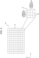
- FIG. 2 is an explanatory diagram of the configuration of the first light receiving unit 20 shown in FIG. 1 .
- the first light receiving unit 20 includes a plurality of pixels 22 arranged two-dimensionally.
- Each pixel that is, one pixel 22 includes a plurality of light receiving elements 24.
- each pixel 22 includes nine SPADs arranged as the light receiving elements 24, three SPADs arranged in the X direction (for example, the horizontal direction) and three SPADs arranged in the Y direction (for example, the vertical direction).
- the light receiving element 24 implemented by the SPAD outputs a pulse signal when detecting light particles (hereinafter also referred to as photons).
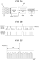
- FIG. 3A is an explanatory diagram of the signal processing unit 462 shown in FIG. 1 .
- FIG. 3B is a diagram showing an example of the output of an addition unit 462A and the output of a comparison unit 462B shown in FIG. 1 .
- the signal processing unit 462 includes the addition unit 462A, the comparison unit 462B, and a histogram generation unit 462C.
- the signal processing unit 462 generates a histogram used in a time correlated single photon counting (TCSPC) method based on the output signal of each pixel 22 of the first light receiving unit 20.
- TCSPC time correlated single photon counting
- the addition unit 462A adds output signals of the plurality of light receiving elements 24 (SPADs) constituting the pixel 22.
- the addition unit 462A may adjust (shape) the pulse width output by the light receiving element 24 and then add the output signals of the plurality of light receiving elements 24.
- the comparison unit 462B compares the output signal of the addition unit 462A with a threshold, and outputs a signal when the output signal of the addition unit 462A is equal to or greater than the threshold.
- the timing at which the comparison unit 462B outputs a signal is considered to be the timing at which the light receiving element 24 of the first light receiving unit 20 detects light.
- the photons of the ambient light are temporally and randomly incident on each of the light receiving elements 24.
- the photons of the reflected light are incident on each of the light receiving elements 24 at a predetermined delay time (a time of flight depending on the distance to the object 50) after the light is emitted. Therefore, when the photons of the ambient light are temporally and randomly incident on the light receiving element 24, the chance is low that the output signal of the addition unit 462A becomes equal to or greater than the threshold.
- the addition unit 462A adds the output signals of the plurality of light receiving elements 24, and the comparison unit 462B compares the output signal of the addition unit 462A with the threshold. Accordingly, it is possible to measure the time at which the reflected light is considered to be detected in the light receiving element 24.
- the addition unit 462A adds the output signals of the plurality of light receiving elements 24 (SPADs), so that it is possible to reduce the influence of the occurrence of the hold-off-time.
- FIG. 3C is an explanatory diagram of a histogram generated by the histogram generation unit 462C shown in FIG. 3A and a time of flight TOF detected based on the histogram.
- the horizontal axis represents time
- the vertical axis represents frequency (number of times).
- the histogram generation unit 462C generates a histogram by repeatedly measuring the time when the light receiving element 24 of each pixel 22 of the first light receiving unit 20 detects light based on the output of the comparison unit 462B, and incrementing the frequency (the number of times) associated with the time. When incrementing the frequency (the number of times), the histogram generation unit 462C may increase the number corresponding to the output signal (the addition value) of the addition unit 462Ainstead of increasing the number by one.
- the setting unit 44 sets in advance the integration number of times for generating the histogram.
- the timing control unit 42 causes the light emitting unit 10 to emit the measurement light a plurality of times according to the set integration number of times. For one time of emission of the measurement light from the light emitting unit 10, a signal is output once or a plurality of times from the addition unit 462A.
- the histogram generation unit 462C increments the frequency (the number of times) according to the output signal of the comparison unit 462B until the set integration number of times is reached, thereby generating a histogram.
- the time detection unit 464 of the distance measuring unit 46 detects the time of flight TOF from when light is emitted until the reflected light reaches based on the histogram. As shown in FIG. 3C , the time detection unit 464 of the distance measuring unit 46 detects the time (the time of flight TOF of light) corresponding to the peak of the frequency of the histogram.
- the distance calculation unit 466 calculates the distance to the object 50 according to Equation (1).
- the second light receiving unit 30 shown in FIG. 1 receives light having a wavelength different from that of the reflected light (the infrared light) as described above. Therefore, the second light receiving unit 30 includes a sensor (for example, a photodiode) capable of detecting light (for example, sunlight) having a wavelength different from that of the reflected light (the infrared light).
- the sensor (not shown) of the second light receiving unit 30 is provided in the same direction as the light receiving surface of the first light receiving unit 20, and receives light from the measurement area according to an instruction from the control unit 40.
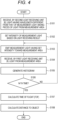
- FIG. 4 is a flow diagram showing processing executed by the control unit 40 according to a first embodiment.
- the timing control unit 42 of the control unit 40 causes the second light receiving unit 30 to receive, among pieces of the light from the measurement area, light (ambient light, hereinafter referred to as sunlight) having a wavelength different from that of the measurement light (S101). Then, the setting unit 44 of the control unit 40 sets the intensity of the measurement light (the infrared light) emitted by the light emitting unit 10 based on the light receiving result (S102). For example, the intensity of the measurement light is set to increase as the intensity of the light of the sunlight increases.
- the timing control unit 42 controls the light emitting unit 10 to emit the measurement light (the infrared light) having the intensity set in step S102 toward the measurement area (S103).
- the timing control unit 42 causes the first light receiving unit 20 to receive the light (including the reflected light and the sunlight) from the measurement area (S104).
- the timing control unit 42 causes the first light receiving unit 20 to repeatedly receive light for one time of light emission.
- the histogram generation unit 462C of the signal processing unit 462 in the distance measuring unit 46 generates a histogram indicating the frequency for each time based on the output (the comparison result) of the comparison unit 462B obtained by comparing the output (the addition result) of the addition unit 462A with a predetermined threshold (S 105).
- step S106 When the integration number of times is not the n-th time (that is, less than n) (No in step S106), the control unit 40 returns to step S103 and causes the light emitting unit 10 to emit the measurement light again.
- step S 106 when the integration number of times is the n-th time in step S 106 (Yes in step S106), the time detection unit 464 of the distance measuring unit 46 obtains the peak of the generated histogram and calculates the time (the time of flight TOF) from the timing of light emission to the peak (S 107).
- the distance calculation unit 466 of the distance measuring unit 46 calculates the distance to the object according to Equation (1) using the time of flight TOF (S108).
- the setting unit 44 of the control unit 40 of the measurement apparatus 1 sets the intensity of the measurement light emitted by the light emitting unit 10 based on the light receiving result of the second light receiving unit 30. Accordingly, when the amount of ambient light is large, the detection accuracy can be maintained by increasing the intensity of the measurement light. When the amount of ambient light is small, the power consumption can be reduced by reducing the intensity of the measurement light.
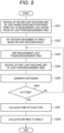
- FIG. 5 is a flow diagram showing a modification 1 of the processing executed by the control unit 40 shown in FIG. 1 .
- the configuration of the measurement apparatus 1 is the same as that of the above embodiment.
- the setting unit 44 according to the modification 1 determines the integration number of times n based on the light receiving result of the second light receiving unit 30.
- the timing control unit 42 of the control unit 40 causes the second light receiving unit 30 to receive, among pieces of the light from the measurement area, light (ambient light, for example, sunlight) having a wavelength different from that of the measurement light (S201). Then, the setting unit 44 of the control unit 40 sets (determines) the integration number of times n based on the light receiving result (S202). For example, the setting unit 44 sets the integration number of times n to increase as the ambient light is stronger.
- the timing control unit 42 controls the light emitting unit 10 to emit the measurement light (the infrared light) having a predetermined intensity toward the measurement area (S203). Further, the timing control unit 42 causes the first light receiving unit 20 to receive the light (including the infrared light and the sunlight) from the measurement area (S204). The timing control unit 42 causes the first light receiving unit 20 to repeatedly receive light for one time of light emission.
- the histogram generation unit 462C of the signal processing unit 462 in the distance measuring unit 46 generates a histogram based on the output (the comparison result) of the comparison unit 462B obtained by comparing the output (the addition result) of the addition unit 462A with the predetermined threshold (S205).
- step S206 When the integration number of times is not the n-th time (that is, less than n) (No in step S206), the control unit 40 returns to step S203 and causes the light emitting unit 10 to emit the measurement light again.
- the time detection unit 464 of the distance measuring unit 46 obtains the peak of the generated histogram and calculates the time of flight TOF which is a time from the timing of light emission to the peak (S207).
- the distance calculation unit 466 of the distance measuring unit 46 calculates the distance to the object according to Equation (1) using the time of flight TOF (S208).
- the setting unit 44 according to the modification 1 sets the integration number of times n based on the light receiving result of the second light receiving unit 30. Accordingly, the integration number of times can be optimized according to the situation of ambient light. For example, when the amount of ambient light is large, the detection accuracy can be maintained by setting the integration number of times n to be large. When the amount of ambient light is small, the measurement speed can be improved by setting the integration number of times n to be small.
- FIG. 6 is a flow diagram showing a modification 2 of the processing executed by the control unit 40 shown in FIG. 1 .
- the configuration of the measurement apparatus 1 is the same as that of the above embodiment.
- a threshold (see FIGS. 3A and 3B ) to be compared with the output of the addition unit 462A by the comparison unit 462B is set based on the light receiving result of the second light receiving unit 30.
- the timing control unit 42 of the control unit 40 causes the second light receiving unit 30 to receive, among pieces of the light from the measurement area, light (ambient light, for example, sunlight) having a wavelength different from that of the measurement light (S301). Then, the setting unit 44 of the control unit 40 determines the threshold based on the light receiving result (S302).
- the threshold is a small value
- the histogram is greatly affected by the ambient light when the amount of ambient light is large, and thus the detection accuracy of the arrival time of light may decrease.
- the threshold is a large value
- the setting unit 44 sets the threshold to a small value. Accordingly, the generation speed of the histogram can be increased.
- the timing control unit 42 controls the light emitting unit 10 to emit the measurement light (the infrared light) having a predetermined intensity to the measurement area (S303). Further, the timing control unit 42 causes the first light receiving unit 20 to receive the light (including the infrared light and the sunlight) from the measurement area (S304). The timing control unit 42 causes the first light receiving unit 20 to repeatedly receive light for one time of light emission.
- the histogram generation unit 462C of the signal processing unit 462 in the distance measuring unit 46 generates a histogram based on the output (the comparison result) of the comparison unit 462B obtained by comparing the addition result of the addition unit 462A with the threshold set in step S302 (S305).
- step S306 When the integration number of times is not the n-th time (that is, less than n) (No in step S306), the control unit 40 returns to step S303 and causes the light emitting unit 10 to emit the measurement light again.
- the time detection unit 464 of the distance measuring unit 46 obtains the peak of the generated histogram and calculates the time of flight TOF which is a time from the timing of light emission to the peak (S307).
- the distance calculation unit 466 of the distance measuring unit 46 calculates the distance to the object 50 according to Equation (1) using the time of flight TOF (S308).
- the setting unit 44 sets the threshold for generating the histogram based on the light receiving result of the second light receiving unit 30. Accordingly, when the amount of ambient light is large, the detection accuracy can be maintained by setting the threshold to a large value. When the amount of ambient light is small, the generation speed of the histogram can be increased by setting the threshold to a small value.
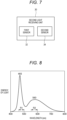
- FIG. 7 is an explanatory diagram of the configuration of the second light receiving unit 30 of the measurement apparatus 1 according to a second embodiment.
- the second light receiving unit 30 includes two sensors (a first sensor 32 and a second sensor 34) having different detection ranges as sensors that receive light having a wavelength different from that of the measurement light (the infrared light) emitted by the light emitting unit 10.
- the first sensor 32 is a sensor capable of detecting blue light
- the second sensor 34 is a sensor capable of detecting yellow light.
- the object 50 (hereinafter, referred to as an oncoming vehicle) according to the second embodiment includes a white LED as a light source of a lamp (for example, a low beam, a daytime running lamp (DRL), or the like) of the vehicle.
- the white LED is formed of a combination of a blue LED and a yellow phosphor. That is, the light generated by the blue LED is emitted through the yellow phosphor. Accordingly, white light is emitted.
- the second light receiving unit 30 of the measurement apparatus 1 detects the light emitted from the white LED of the oncoming vehicle.
- FIG. 8 is an explanatory diagram of a spectrum of a white LED.
- the horizontal axis represents the wavelength
- the vertical axis represents the energy of light.
- the spectrum of the white LED includes two peaks of a peak at a wavelength of approximately 465 nm and a peak at a wavelength of approximately 560 nm.
- the peak at approximately 465 nm is the center wavelength of the light emitted from the blue LED
- the peak at approximately 560 nm is the center wavelength of the light emitted from the yellow phosphor.
- a region R1 shown in FIG. 8 is a detectable region of the first sensor 32 capable of detecting blue light.
- the region R2 is a detectable region of the second sensor 34 capable of detecting yellow light.
- the first sensor 32 can detect light having a wavelength of 465 nm
- the second sensor 34 can detect light having a wavelength of 560 nm.
- the wavelength of the region R1 that can be detected by the first sensor 32 corresponds to a "first wavelength”
- the wavelength of the region R2 that can be detected by the second sensor 34 corresponds to a "second wavelength".
- the presence of the object 50 can be determined based on the detection results (the light intensity ratios) of the first sensor 32 and the second sensor 34.
- FIG. 9 is a flow diagram showing the processing of the control unit 40 according to the second embodiment.
- the timing control unit 42 of the control unit 40 causes the second light receiving unit 30 to receive the light from the measurement area (S401).
- the control unit 40 detects the intensity of the blue light, that is, the light having the center wavelength of 465 nm, based on the light receiving result of the first sensor 32 of the second light receiving unit 30 (S402).
- the control unit 40 detects the intensity of the yellow light, that is, the light having the center wavelength of 560 nm, based on the light receiving result of the second sensor 34 of the second light receiving unit 30 (S403).
- the determination unit 48 of the control unit 40 determines the presence or absence of the oncoming vehicle based on the ratio between the intensity of the blue light and the intensity of the yellow light (S404). For example, when the intensity of the blue light is higher than the intensity of the yellow light, the determination unit 48 determines that the light emitted from the white LED of the oncoming vehicle is present, that is, the oncoming vehicle is present. When the intensity of the yellow light is higher than the intensity of the blue light (for example, sunlight), the determination unit 48 determines that no light emitted from the oncoming vehicle is present, that is, no oncoming vehicle is present.
- the intensity of the blue light for example, sunlight
- the second light receiving unit 30 of the measurement apparatus 1 includes the first sensor 32 capable of detecting the blue light and the second sensor 34 capable of detecting the yellow light. Accordingly, the determination unit 48 can determine the presence or absence of the oncoming vehicle (the object 50) based on the ratio between the intensity of the blue light detected by the first sensor 32 and the intensity of the yellow light detected by the second sensor 34.
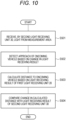
- FIG. 10 is a flow diagram showing a modification of the processing of the control unit 40 according to the second embodiment.
- the control unit 40 of the measurement apparatus 1 detects the approach of an oncoming vehicle based on the detection result of the second light receiving unit 30.
- control unit 40 causes the first sensor 32 and the second sensor 34 of the second light receiving unit 30 to receive the light from the measurement area (S501).
- the first sensor 32 receives the blue light
- the second sensor 34 receives the yellow light.
- the presence or absence of the oncoming vehicle (the object 50) can be detected according to the light receiving result.
- the control unit 40 detects the approach of the oncoming vehicle based on the change in the light receiving result (the light receiving amount) of the second light receiving unit 30 with the passage of time (S502). For example, when an oncoming vehicle approaches, the light receiving amount of the first sensor 32 and the light receiving amount of the second sensor 34 both increase with the passage of time. Accordingly, the determination unit 48 of the control unit 40 determines that the oncoming vehicle is approaching based on the change in the light receiving result of the second light receiving unit 30.
- the distance measuring unit 46 of the control unit 40 calculates the distance to the oncoming vehicle (the object 50) based on the light receiving result of the first light receiving unit 20 (S503).
- control unit 40 compares the change in the distance (see the first embodiment) to the oncoming vehicle calculated based on the detection result of the first light receiving unit 20 with the change in the light receiving result of the second light receiving unit 30 (S504). Accordingly, the reliability of the measurement of the distance to the oncoming vehicle (the object 50) can be improved.
- the measurement apparatus 1 includes the light emitting unit 10, the first light receiving unit 20, the second light receiving unit 30, and the control unit 40.
- the light emitting unit 10 emits measurement light (infrared light) toward the measurement area.
- the first light receiving unit 20 receives the reflected light from the measurement area, that is, the measurement light reflected by the object 50.
- the control unit 40 controls the light emitting unit 10 and the first light receiving unit 20, and calculates the distance to the object 50 in the measurement area based on the light receiving result of the first light receiving unit 20.
- the second light receiving unit 30 receives light having a wavelength different from that of the measurement light among pieces of the light from the measurement area. Accordingly, the detection performance can be improved.
- the control unit 40 calculates the distance to the object 50 based on the light receiving result of the second light receiving unit 30. Accordingly, the influence of ambient light (sunlight or the like) can be reduced, and the measurement accuracy can be improved.
- the setting unit 44 sets the intensity of the measurement light emitted from the light emitting unit 10 based on the light receiving result of the second light receiving unit 30. Then, the control unit 40 calculates the distance based on the light receiving result of the first light receiving unit 20 in response to the light emitting unit 10 emitting the measurement light having the intensity. In this way, when the amount of ambient light is large, the detection accuracy can be maintained by increasing the intensity of the measurement light. When the amount of ambient light is small, the power consumption can be reduced by reducing the intensity of the measurement light.
- the setting unit 44 determines the integration number of times n based on the light receiving result of the second light receiving unit 30. Then, the control unit 40 causes the first light receiving unit 20 to receive the reflected light by the determined integration number of times n, and calculates the distance based on the light receiving result of the first light receiving unit 20 in accordance with the integration number of times n. Accordingly, when the amount of ambient light is large, the detection accuracy can be maintained by setting the integration number of times n to be large. When the amount of ambient light is small, the measurement speed can be improved by setting the integration number of times n to be small.
- the distance measuring unit 46 of the control unit 40 includes the addition unit 462A, the comparison unit 462B, and the histogram generation unit 462C.
- the addition unit 462A adds the outputs of the plurality of light receiving elements 24, and the comparison unit 462B compares the output of the addition unit 462A with a threshold.
- the histogram generation unit 462C generates a histogram based on the comparison result of the comparison unit 462B.
- the time detection unit 464 detects a time of flight TOF which is an arrival time of light based on the peak of the histogram.
- the setting unit 44 according to the modification 2 of the first embodiment sets the threshold based on the light receiving result of the second light receiving unit 30. Accordingly, when the amount of ambient light is large, the detection accuracy can be maintained by setting the threshold to a large value. When the amount of ambient light is small, the generation speed of the histogram can be increased by setting the threshold to a small value.
- the control unit 40 determines the presence or absence of the oncoming vehicle (the object 50) based on the light receiving result of the second light receiving unit 30.
- the second light receiving unit 30 according to the second embodiment includes a first sensor 32 and a second sensor 34 that can detect light having different wavelengths.
- the determination unit 48 of the control unit 40 determines the presence or absence of the oncoming vehicle based on the ratio between the intensity of light based on the detection result of the first sensor 32 and the intensity of light based on the detection result of the second sensor 34. Accordingly, the detection performance for the oncoming vehicle can be improved.
- the first sensor 32 can detect blue light (light having a wavelength of 465 nm), and the second sensor 34 can detect yellow light (light having a wavelength of 560 nm). Accordingly, the light of the white LED of the oncoming vehicle can be detected.
- the control unit 40 detects approach of an oncoming vehicle based on a change in the light receiving result of the second light receiving unit 30. Accordingly, the approach of the oncoming vehicle can be detected based on the light receiving result of the second light receiving unit 30.
- control unit 40 compares the change in the calculated distance with the change in the light receiving result of the second light receiving unit 30 based on the light receiving result of the first light receiving unit 20. Accordingly, the reliability of the distance measurement can be improved.
Landscapes
- Engineering & Computer Science (AREA)
- Physics & Mathematics (AREA)
- Computer Networks & Wireless Communication (AREA)
- General Physics & Mathematics (AREA)
- Radar, Positioning & Navigation (AREA)
- Remote Sensing (AREA)
- Electromagnetism (AREA)
- Optical Radar Systems And Details Thereof (AREA)
- Measurement Of Optical Distance (AREA)
Abstract
Description
- The present invention relates to a measurement apparatus.
- A measurement apparatus configured to measure a distance to an object based on emitting light and receiving reflected light reflected back from the object is known (for example, see Patent Literature 1).
- Patent Literature 1:
JP2021-152536A - The light received by the measurement apparatus includes not only reflected light but also ambient light (noise) such as sunlight and light of an oncoming vehicle. Since the measurement apparatus described above can not distinguish such light, the detection performance may deteriorate at the time of light reception due to noise.
- An object of the present invention is to improve the detection performance.
- One of the present inventions for achieving the above object is a measurement apparatus including: a light emitting unit configured to emit measurement light toward a measurement area; a first light receiving unit configured to receive reflected light from the measurement area; a control unit configured to control the light emitting unit and the first light receiving unit and calculate a distance to an object in the measurement area based on a light receiving result of the first light receiving unit; and a second light receiving unit configured to receive, among pieces of light from the measurement area, light having a wavelength different from that of the measurement light.
- According to the present invention, the detection performance can be improved.
-
- [
FIG. 1] FIG. 1 is an overall configuration diagram including a measurement apparatus 1 according to the present embodiment. - [
FIG. 2] FIG. 2 is an explanatory diagram of the configuration of a firstlight receiving unit 20 shown inFIG. 1 . - [
FIG. 3A] FIG. 3A is an explanatory diagram of asignal processing unit 462 shown inFIG. 1 . - [
FIG. 3B] FIG. 3B is a diagram showing the output of anaddition unit 462A and the output of acomparison unit 462B shown inFIG. 1 . - [
FIG. 3C] FIG. 3C is an explanatory diagram of a histogram generated by ahistogram generation unit 462C shown inFIG. 3A and a time of flight TOF detected based on the histogram. - [
FIG. 4] FIG. 4 is a flow diagram showing processing executed by acontrol unit 40 according to a first embodiment. - [
FIG. 5] FIG. 5 is a flow diagram showing a modification of the processing executed by thecontrol unit 40 shown inFIG. 1 . - [
FIG. 6] FIG. 6 is a flow diagram showing another modification of the processing executed by thecontrol unit 40 shown inFIG. 1 . - [
FIG. 7] FIG. 7 is an explanatory diagram of the configuration of a secondlight receiving unit 30 of the measurement apparatus 1 according to a second embodiment. - [
FIG. 8] FIG. 8 is an explanatory diagram of a spectrum of a white LED. - [
FIG. 9] FIG. 9 is a flow diagram showing the processing of thecontrol unit 40 according to the second embodiment. - [
FIG. 10] FIG. 10 is a flow diagram showing a modification of the processing of thecontrol unit 40 according to the second embodiment. - Hereinafter, embodiments of the present invention will be described with reference to the drawings. In the following description, the same or similar configurations are denoted by the same reference signs, and the redundant description thereof may be omitted.
-
FIG. 1 is an overall configuration diagram including a measurement apparatus 1 according to the present embodiment. - The measurement apparatus 1 shown in
FIG. 1 is a measurement apparatus having a function as so-called light detection and ranging and laser imaging detection and ranging (LiDAR). The measurement apparatus 1 measures the distance to anobject 50 by a time of flight (TOF) method by emitting measurement light (infrared light in the present embodiment) and measuring the time until the measurement light is reflected back from theobject 50. The measurement apparatus 1 according to the present embodiment is mounted on a vehicle, and theobject 50 is another vehicle (an oncoming vehicle). The light (the return light) that is reflected back from theobject 50 is also referred to as "reflected light". - As shown in
FIG. 1 , the measurement apparatus 1 includes alight emitting unit 10, a firstlight receiving unit 20, a secondlight receiving unit 30, and acontrol unit 40. - The
light emitting unit 10 emits measurement light (here, infrared light) to a space (hereinafter, a measurement area) to be measured. Thelight emitting unit 10 includes, for example, a surface emitting element array (a VCSEL array) including a plurality of surface emitting type laser elements (vertical cavity surface emitting lasers (VCSELs)) arranged one-dimensionally or two-dimensionally, and a light projection optical system (both not shown) such as a lens that adjusts distribution of emitted light. - The first
light receiving unit 20 receives reflected light (infrared light) from theobject 50 in the measurement area. In the firstlight receiving unit 20 according to the present embodiment, a single photon avalanche diode (SPAD) is used as a sensor (a light receiving element) that detects light. Details of the firstlight receiving unit 20 will be described later. - The second light
receiving unit 30 receives, among pieces of the light from the measurement area, light (for example, ambient light such as sunlight or light from an oncoming vehicle) having a wavelength different from that of the reflected light. - The
control unit 40 controls the measurement apparatus 1. Thecontrol unit 40 is implemented by a hardware configuration such as an element and a circuit. Examples of the element include a memory and a CPU. Thecontrol unit 40 implements a predetermined function by the CPU executing a program stored in the memory.FIG. 1 shows various functions implemented by thecontrol unit 40. Thecontrol unit 40 includes atiming control unit 42, asetting unit 44, adistance measuring unit 46, and adetermination unit 48. - The
timing control unit 42 controls various timings such as a timing at which thelight emitting unit 10 emits light. - The
setting unit 44 executes various settings of the measurement apparatus 1. For example, the intensity of the measurement light emitted from thelight emitting unit 10, the integration number of times when a histogram is created, a threshold, and the like are set. - The
distance measuring unit 46 measures the distance to theobject 50. Thedistance measuring unit 46 includes asignal processing unit 462, atime detection unit 464, and adistance calculation unit 466. Thesignal processing unit 462 processes the output signal of the firstlight receiving unit 20. Thetime detection unit 464 detects the arrival time (the time of flight of light: TOF) from when thelight emitting unit 10 emits the measurement light until the reflected light reaches the firstlight receiving unit 20. Thedistance calculation unit 466 calculates the distance to theobject 50 based on the time of flight TOF of the light. - The
determination unit 48 determines a situation such as the presence or approach of an oncoming vehicle based on the light receiving result of the secondlight receiving unit 30. The determination of thedetermination unit 48 will be described later. -
FIG. 2 is an explanatory diagram of the configuration of the firstlight receiving unit 20 shown inFIG. 1 . - As shown in
FIG. 2 , the firstlight receiving unit 20 includes a plurality ofpixels 22 arranged two-dimensionally. Each pixel, that is, onepixel 22 includes a plurality of light receivingelements 24. Here, eachpixel 22 includes nine SPADs arranged as thelight receiving elements 24, three SPADs arranged in the X direction (for example, the horizontal direction) and three SPADs arranged in the Y direction (for example, the vertical direction). Thelight receiving element 24 implemented by the SPAD outputs a pulse signal when detecting light particles (hereinafter also referred to as photons). -
FIG. 3A is an explanatory diagram of thesignal processing unit 462 shown inFIG. 1 .FIG. 3B is a diagram showing an example of the output of anaddition unit 462A and the output of acomparison unit 462B shown inFIG. 1 . Thesignal processing unit 462 includes theaddition unit 462A, thecomparison unit 462B, and ahistogram generation unit 462C. Here, thesignal processing unit 462 generates a histogram used in a time correlated single photon counting (TCSPC) method based on the output signal of eachpixel 22 of the firstlight receiving unit 20. - The
addition unit 462A adds output signals of the plurality of light receiving elements 24 (SPADs) constituting thepixel 22. The addition unit 462Amay adjust (shape) the pulse width output by thelight receiving element 24 and then add the output signals of the plurality of light receivingelements 24. Thecomparison unit 462B compares the output signal of theaddition unit 462A with a threshold, and outputs a signal when the output signal of theaddition unit 462A is equal to or greater than the threshold. The timing at which thecomparison unit 462B outputs a signal is considered to be the timing at which thelight receiving element 24 of the firstlight receiving unit 20 detects light. - The photons of the ambient light are temporally and randomly incident on each of the
light receiving elements 24. On the other hand, the photons of the reflected light are incident on each of thelight receiving elements 24 at a predetermined delay time (a time of flight depending on the distance to the object 50) after the light is emitted. Therefore, when the photons of the ambient light are temporally and randomly incident on thelight receiving element 24, the chance is low that the output signal of theaddition unit 462A becomes equal to or greater than the threshold. On the other hand, when the photons of the reflected light are incident on thelight receiving element 24, since the plurality of light receivingelements 24 constituting thepixel 22 simultaneously detect the photons, the chance is high that the output signal of theaddition unit 462A becomes equal to or greater than the threshold. Therefore, theaddition unit 462A adds the output signals of the plurality of light receivingelements 24, and thecomparison unit 462B compares the output signal of theaddition unit 462A with the threshold. Accordingly, it is possible to measure the time at which the reflected light is considered to be detected in thelight receiving element 24. - When the
light receiving element 24 detects the photons once, a hold-off-time (a dead-time) occurs. However, theaddition unit 462A adds the output signals of the plurality of light receiving elements 24 (SPADs), so that it is possible to reduce the influence of the occurrence of the hold-off-time. -
FIG. 3C is an explanatory diagram of a histogram generated by thehistogram generation unit 462C shown inFIG. 3A and a time of flight TOF detected based on the histogram. InFIG. 3C , the horizontal axis represents time, and the vertical axis represents frequency (number of times). Thehistogram generation unit 462C generates a histogram by repeatedly measuring the time when thelight receiving element 24 of eachpixel 22 of the firstlight receiving unit 20 detects light based on the output of thecomparison unit 462B, and incrementing the frequency (the number of times) associated with the time. When incrementing the frequency (the number of times), thehistogram generation unit 462C may increase the number corresponding to the output signal (the addition value) of the addition unit 462Ainstead of increasing the number by one. - As described above, the setting unit 44 (see
FIG. 1 ) sets in advance the integration number of times for generating the histogram. Thetiming control unit 42 causes thelight emitting unit 10 to emit the measurement light a plurality of times according to the set integration number of times. For one time of emission of the measurement light from thelight emitting unit 10, a signal is output once or a plurality of times from theaddition unit 462A. Thehistogram generation unit 462C increments the frequency (the number of times) according to the output signal of thecomparison unit 462B until the set integration number of times is reached, thereby generating a histogram. - After the histogram is generated, the
time detection unit 464 of thedistance measuring unit 46 detects the time of flight TOF from when light is emitted until the reflected light reaches based on the histogram. As shown inFIG. 3C , thetime detection unit 464 of thedistance measuring unit 46 detects the time (the time of flight TOF of light) corresponding to the peak of the frequency of the histogram. Thedistance calculation unit 466 of thedistance measuring unit 46 calculates the distance to theobject 50 based on the time of flight TOF. Since the light travels twice the distance to the object during the time of flight TOF, when the speed of the light is Co and the time of flight TOF is Tf, the distance L to the object is explained as follows:
- The
distance calculation unit 466 calculates the distance to theobject 50 according to Equation (1). - The second
light receiving unit 30 shown inFIG. 1 receives light having a wavelength different from that of the reflected light (the infrared light) as described above. Therefore, the secondlight receiving unit 30 includes a sensor (for example, a photodiode) capable of detecting light (for example, sunlight) having a wavelength different from that of the reflected light (the infrared light). The sensor (not shown) of the secondlight receiving unit 30 is provided in the same direction as the light receiving surface of the firstlight receiving unit 20, and receives light from the measurement area according to an instruction from thecontrol unit 40. -
FIG. 4 is a flow diagram showing processing executed by thecontrol unit 40 according to a first embodiment. - First, the
timing control unit 42 of thecontrol unit 40 causes the secondlight receiving unit 30 to receive, among pieces of the light from the measurement area, light (ambient light, hereinafter referred to as sunlight) having a wavelength different from that of the measurement light (S101). Then, the settingunit 44 of thecontrol unit 40 sets the intensity of the measurement light (the infrared light) emitted by thelight emitting unit 10 based on the light receiving result (S102). For example, the intensity of the measurement light is set to increase as the intensity of the light of the sunlight increases. - Next, the
timing control unit 42 controls thelight emitting unit 10 to emit the measurement light (the infrared light) having the intensity set in step S102 toward the measurement area (S103). Thetiming control unit 42 causes the firstlight receiving unit 20 to receive the light (including the reflected light and the sunlight) from the measurement area (S104). Thetiming control unit 42 causes the firstlight receiving unit 20 to repeatedly receive light for one time of light emission. - The
histogram generation unit 462C of thesignal processing unit 462 in thedistance measuring unit 46 generates a histogram indicating the frequency for each time based on the output (the comparison result) of thecomparison unit 462B obtained by comparing the output (the addition result) of theaddition unit 462A with a predetermined threshold (S 105). - When the integration number of times is not the n-th time (that is, less than n) (No in step S106), the
control unit 40 returns to step S103 and causes thelight emitting unit 10 to emit the measurement light again. - On the other hand, when the integration number of times is the n-th time in step S 106 (Yes in step S106), the
time detection unit 464 of thedistance measuring unit 46 obtains the peak of the generated histogram and calculates the time (the time of flight TOF) from the timing of light emission to the peak (S 107). - Next, the
distance calculation unit 466 of thedistance measuring unit 46 calculates the distance to the object according to Equation (1) using the time of flight TOF (S108). - As described above, the setting
unit 44 of thecontrol unit 40 of the measurement apparatus 1 according to the present embodiment sets the intensity of the measurement light emitted by thelight emitting unit 10 based on the light receiving result of the secondlight receiving unit 30. Accordingly, when the amount of ambient light is large, the detection accuracy can be maintained by increasing the intensity of the measurement light. When the amount of ambient light is small, the power consumption can be reduced by reducing the intensity of the measurement light. -
FIG. 5 is a flow diagram showing a modification 1 of the processing executed by thecontrol unit 40 shown inFIG. 1 . The configuration of the measurement apparatus 1 is the same as that of the above embodiment. The settingunit 44 according to the modification 1 determines the integration number of times n based on the light receiving result of the secondlight receiving unit 30. - First, the
timing control unit 42 of thecontrol unit 40 causes the secondlight receiving unit 30 to receive, among pieces of the light from the measurement area, light (ambient light, for example, sunlight) having a wavelength different from that of the measurement light (S201). Then, the settingunit 44 of thecontrol unit 40 sets (determines) the integration number of times n based on the light receiving result (S202). For example, the settingunit 44 sets the integration number of times n to increase as the ambient light is stronger. - Next, the
timing control unit 42 controls thelight emitting unit 10 to emit the measurement light (the infrared light) having a predetermined intensity toward the measurement area (S203). Further, thetiming control unit 42 causes the firstlight receiving unit 20 to receive the light (including the infrared light and the sunlight) from the measurement area (S204). Thetiming control unit 42 causes the firstlight receiving unit 20 to repeatedly receive light for one time of light emission. - The
histogram generation unit 462C of thesignal processing unit 462 in thedistance measuring unit 46 generates a histogram based on the output (the comparison result) of thecomparison unit 462B obtained by comparing the output (the addition result) of theaddition unit 462A with the predetermined threshold (S205). - When the integration number of times is not the n-th time (that is, less than n) (No in step S206), the
control unit 40 returns to step S203 and causes thelight emitting unit 10 to emit the measurement light again. - On the other hand, when the integration number of times is the n-th time (Yes in step S206), the
time detection unit 464 of thedistance measuring unit 46 obtains the peak of the generated histogram and calculates the time of flight TOF which is a time from the timing of light emission to the peak (S207). - Next, the
distance calculation unit 466 of thedistance measuring unit 46 calculates the distance to the object according to Equation (1) using the time of flight TOF (S208). - As described above, the setting
unit 44 according to the modification 1 sets the integration number of times n based on the light receiving result of the secondlight receiving unit 30. Accordingly, the integration number of times can be optimized according to the situation of ambient light. For example, when the amount of ambient light is large, the detection accuracy can be maintained by setting the integration number of times n to be large. When the amount of ambient light is small, the measurement speed can be improved by setting the integration number of times n to be small. -
FIG. 6 is a flow diagram showing a modification 2 of the processing executed by thecontrol unit 40 shown inFIG. 1 . The configuration of the measurement apparatus 1 is the same as that of the above embodiment. In the modification 2, a threshold (seeFIGS. 3A and 3B ) to be compared with the output of theaddition unit 462A by thecomparison unit 462B is set based on the light receiving result of the secondlight receiving unit 30. - First, the
timing control unit 42 of thecontrol unit 40 causes the secondlight receiving unit 30 to receive, among pieces of the light from the measurement area, light (ambient light, for example, sunlight) having a wavelength different from that of the measurement light (S301). Then, the settingunit 44 of thecontrol unit 40 determines the threshold based on the light receiving result (S302). - When the threshold is a small value, the histogram is greatly affected by the ambient light when the amount of ambient light is large, and thus the detection accuracy of the arrival time of light may decrease. On the other hand, when the threshold is a large value, it may take time to generate the histogram of the predetermined integration number of times. Therefore, in the present embodiment, based on the light receiving result of the second
light receiving unit 30, when the amount of ambient light is large, the settingunit 44 sets the threshold to a large value. Accordingly, the detection accuracy can be maintained. Based on the light receiving result of the secondlight receiving unit 30, when the amount of ambient light is small, the settingunit 44 sets the threshold to a small value. Accordingly, the generation speed of the histogram can be increased. - Next, the
timing control unit 42 controls thelight emitting unit 10 to emit the measurement light (the infrared light) having a predetermined intensity to the measurement area (S303). Further, thetiming control unit 42 causes the firstlight receiving unit 20 to receive the light (including the infrared light and the sunlight) from the measurement area (S304). Thetiming control unit 42 causes the firstlight receiving unit 20 to repeatedly receive light for one time of light emission. - The
histogram generation unit 462C of thesignal processing unit 462 in thedistance measuring unit 46 generates a histogram based on the output (the comparison result) of thecomparison unit 462B obtained by comparing the addition result of theaddition unit 462A with the threshold set in step S302 (S305). - When the integration number of times is not the n-th time (that is, less than n) (No in step S306), the
control unit 40 returns to step S303 and causes thelight emitting unit 10 to emit the measurement light again. - On the other hand, when the integration number of times is the n-th time (Yes in step S306), the
time detection unit 464 of thedistance measuring unit 46 obtains the peak of the generated histogram and calculates the time of flight TOF which is a time from the timing of light emission to the peak (S307). - Next, the
distance calculation unit 466 of thedistance measuring unit 46 calculates the distance to theobject 50 according to Equation (1) using the time of flight TOF (S308). - As described above, the setting
unit 44 according to the modification 2 sets the threshold for generating the histogram based on the light receiving result of the secondlight receiving unit 30. Accordingly, when the amount of ambient light is large, the detection accuracy can be maintained by setting the threshold to a large value. When the amount of ambient light is small, the generation speed of the histogram can be increased by setting the threshold to a small value. -
FIG. 7 is an explanatory diagram of the configuration of the secondlight receiving unit 30 of the measurement apparatus 1 according to a second embodiment. - The second
light receiving unit 30 according to the second embodiment includes two sensors (afirst sensor 32 and a second sensor 34) having different detection ranges as sensors that receive light having a wavelength different from that of the measurement light (the infrared light) emitted by thelight emitting unit 10. As will be described later, thefirst sensor 32 is a sensor capable of detecting blue light, and thesecond sensor 34 is a sensor capable of detecting yellow light. - The object 50 (hereinafter, referred to as an oncoming vehicle) according to the second embodiment includes a white LED as a light source of a lamp (for example, a low beam, a daytime running lamp (DRL), or the like) of the vehicle. The white LED is formed of a combination of a blue LED and a yellow phosphor. That is, the light generated by the blue LED is emitted through the yellow phosphor. Accordingly, white light is emitted. The second
light receiving unit 30 of the measurement apparatus 1 detects the light emitted from the white LED of the oncoming vehicle. -
FIG. 8 is an explanatory diagram of a spectrum of a white LED. InFIG. 8 , the horizontal axis represents the wavelength, and the vertical axis represents the energy of light. - As shown in
FIG. 8 , the spectrum of the white LED includes two peaks of a peak at a wavelength of approximately 465 nm and a peak at a wavelength of approximately 560 nm. The peak at approximately 465 nm is the center wavelength of the light emitted from the blue LED, and the peak at approximately 560 nm is the center wavelength of the light emitted from the yellow phosphor. - A region R1 shown in
FIG. 8 is a detectable region of thefirst sensor 32 capable of detecting blue light. The region R2 is a detectable region of thesecond sensor 34 capable of detecting yellow light. As shown inFIG. 8 , thefirst sensor 32 can detect light having a wavelength of 465 nm, and thesecond sensor 34 can detect light having a wavelength of 560 nm. The wavelength of the region R1 that can be detected by thefirst sensor 32 corresponds to a "first wavelength", and the wavelength of the region R2 that can be detected by thesecond sensor 34 corresponds to a "second wavelength". - By providing the
first sensor 32 and thesecond sensor 34 having different detection ranges, the presence of the object 50 (the oncoming vehicle) can be determined based on the detection results (the light intensity ratios) of thefirst sensor 32 and thesecond sensor 34. -
FIG. 9 is a flow diagram showing the processing of thecontrol unit 40 according to the second embodiment. - The
timing control unit 42 of thecontrol unit 40 causes the secondlight receiving unit 30 to receive the light from the measurement area (S401). Thecontrol unit 40 detects the intensity of the blue light, that is, the light having the center wavelength of 465 nm, based on the light receiving result of thefirst sensor 32 of the second light receiving unit 30 (S402). - The
control unit 40 detects the intensity of the yellow light, that is, the light having the center wavelength of 560 nm, based on the light receiving result of thesecond sensor 34 of the second light receiving unit 30 (S403). - Next, the
determination unit 48 of thecontrol unit 40 determines the presence or absence of the oncoming vehicle based on the ratio between the intensity of the blue light and the intensity of the yellow light (S404). For example, when the intensity of the blue light is higher than the intensity of the yellow light, thedetermination unit 48 determines that the light emitted from the white LED of the oncoming vehicle is present, that is, the oncoming vehicle is present. When the intensity of the yellow light is higher than the intensity of the blue light (for example, sunlight), thedetermination unit 48 determines that no light emitted from the oncoming vehicle is present, that is, no oncoming vehicle is present. - As described above, the second
light receiving unit 30 of the measurement apparatus 1 according to the second embodiment includes thefirst sensor 32 capable of detecting the blue light and thesecond sensor 34 capable of detecting the yellow light. Accordingly, thedetermination unit 48 can determine the presence or absence of the oncoming vehicle (the object 50) based on the ratio between the intensity of the blue light detected by thefirst sensor 32 and the intensity of the yellow light detected by thesecond sensor 34. -
FIG. 10 is a flow diagram showing a modification of the processing of thecontrol unit 40 according to the second embodiment. In the modification of the second embodiment, thecontrol unit 40 of the measurement apparatus 1 detects the approach of an oncoming vehicle based on the detection result of the secondlight receiving unit 30. - First, the
control unit 40 causes thefirst sensor 32 and thesecond sensor 34 of the secondlight receiving unit 30 to receive the light from the measurement area (S501). Here, similarly to the above embodiment, thefirst sensor 32 receives the blue light, and thesecond sensor 34 receives the yellow light. The presence or absence of the oncoming vehicle (the object 50) can be detected according to the light receiving result. - The
control unit 40 detects the approach of the oncoming vehicle based on the change in the light receiving result (the light receiving amount) of the secondlight receiving unit 30 with the passage of time (S502). For example, when an oncoming vehicle approaches, the light receiving amount of thefirst sensor 32 and the light receiving amount of thesecond sensor 34 both increase with the passage of time. Accordingly, thedetermination unit 48 of thecontrol unit 40 determines that the oncoming vehicle is approaching based on the change in the light receiving result of the secondlight receiving unit 30. - Similarly to the first embodiment, the
distance measuring unit 46 of thecontrol unit 40 calculates the distance to the oncoming vehicle (the object 50) based on the light receiving result of the first light receiving unit 20 (S503). - Then, the
control unit 40 compares the change in the distance (see the first embodiment) to the oncoming vehicle calculated based on the detection result of the firstlight receiving unit 20 with the change in the light receiving result of the second light receiving unit 30 (S504). Accordingly, the reliability of the measurement of the distance to the oncoming vehicle (the object 50) can be improved. - The measurement apparatus 1 according to the present embodiment has been described above. The measurement apparatus 1 includes the
light emitting unit 10, the firstlight receiving unit 20, the secondlight receiving unit 30, and thecontrol unit 40. Thelight emitting unit 10 emits measurement light (infrared light) toward the measurement area. The firstlight receiving unit 20 receives the reflected light from the measurement area, that is, the measurement light reflected by theobject 50. Thecontrol unit 40 controls thelight emitting unit 10 and the firstlight receiving unit 20, and calculates the distance to theobject 50 in the measurement area based on the light receiving result of the firstlight receiving unit 20. The secondlight receiving unit 30 receives light having a wavelength different from that of the measurement light among pieces of the light from the measurement area. Accordingly, the detection performance can be improved. - The
control unit 40 calculates the distance to theobject 50 based on the light receiving result of the secondlight receiving unit 30. Accordingly, the influence of ambient light (sunlight or the like) can be reduced, and the measurement accuracy can be improved. - Specifically, the setting
unit 44 according to the first embodiment sets the intensity of the measurement light emitted from thelight emitting unit 10 based on the light receiving result of the secondlight receiving unit 30. Then, thecontrol unit 40 calculates the distance based on the light receiving result of the firstlight receiving unit 20 in response to thelight emitting unit 10 emitting the measurement light having the intensity. In this way, when the amount of ambient light is large, the detection accuracy can be maintained by increasing the intensity of the measurement light. When the amount of ambient light is small, the power consumption can be reduced by reducing the intensity of the measurement light. - The setting
unit 44 according to the modification 1 of the first embodiment determines the integration number of times n based on the light receiving result of the secondlight receiving unit 30. Then, thecontrol unit 40 causes the firstlight receiving unit 20 to receive the reflected light by the determined integration number of times n, and calculates the distance based on the light receiving result of the firstlight receiving unit 20 in accordance with the integration number of times n. Accordingly, when the amount of ambient light is large, the detection accuracy can be maintained by setting the integration number of times n to be large. When the amount of ambient light is small, the measurement speed can be improved by setting the integration number of times n to be small. - The
distance measuring unit 46 of thecontrol unit 40 includes theaddition unit 462A, thecomparison unit 462B, and thehistogram generation unit 462C. Theaddition unit 462A adds the outputs of the plurality of light receivingelements 24, and thecomparison unit 462B compares the output of theaddition unit 462A with a threshold. Thehistogram generation unit 462C generates a histogram based on the comparison result of thecomparison unit 462B. Thetime detection unit 464 detects a time of flight TOF which is an arrival time of light based on the peak of the histogram. In such a configuration, the settingunit 44 according to the modification 2 of the first embodiment sets the threshold based on the light receiving result of the secondlight receiving unit 30. Accordingly, when the amount of ambient light is large, the detection accuracy can be maintained by setting the threshold to a large value. When the amount of ambient light is small, the generation speed of the histogram can be increased by setting the threshold to a small value. - The
control unit 40 according to the second embodiment determines the presence or absence of the oncoming vehicle (the object 50) based on the light receiving result of the secondlight receiving unit 30. Specifically, the secondlight receiving unit 30 according to the second embodiment includes afirst sensor 32 and asecond sensor 34 that can detect light having different wavelengths. Thedetermination unit 48 of thecontrol unit 40 determines the presence or absence of the oncoming vehicle based on the ratio between the intensity of light based on the detection result of thefirst sensor 32 and the intensity of light based on the detection result of thesecond sensor 34. Accordingly, the detection performance for the oncoming vehicle can be improved. - The
first sensor 32 can detect blue light (light having a wavelength of 465 nm), and thesecond sensor 34 can detect yellow light (light having a wavelength of 560 nm). Accordingly, the light of the white LED of the oncoming vehicle can be detected. - The
control unit 40 according to the modification of the second embodiment detects approach of an oncoming vehicle based on a change in the light receiving result of the secondlight receiving unit 30. Accordingly, the approach of the oncoming vehicle can be detected based on the light receiving result of the secondlight receiving unit 30. - Further, the
control unit 40 according to the modification of the second embodiment compares the change in the calculated distance with the change in the light receiving result of the secondlight receiving unit 30 based on the light receiving result of the firstlight receiving unit 20. Accordingly, the reliability of the distance measurement can be improved. - The above embodiments are intended to facilitate understanding of the present invention, and are not to be construed as limiting the present invention. It is needless to say that the present invention can be modified or improved without departing from the gist thereof, and equivalents thereof are included in the present invention.
- The present application is based on a
Japanese patent application No. 2022-018762 filed on February 9, 2022
Claims (11)
- A measurement apparatus comprising:a light emitting unit configured to emit measurement light toward a measurement area;a first light receiving unit configured to receive reflected light from the measurement area;a control unit configured to control the light emitting unit and the first light receiving unit and calculate a distance to an object in the measurement area based on a light receiving result of the first light receiving unit; anda second light receiving unit configured to receive, among pieces of light from the measurement area, light having a wavelength different from that of the measurement light.
- The measurement apparatus according to claim 1,
wherein the control unit is configured to calculate the distance based on a light receiving result of the second light receiving unit. - The measurement apparatus according to claim 2,
wherein the control unit is configured to:set an intensity of the measurement light emitted from the light emitting unit based on the light receiving result of the second light receiving unit; andcalculate the distance based on the light receiving result of the first light receiving unit in response to emission of the measurement light having the intensity in accordance with the light receiving result of the second light receiving unit. - The measurement apparatus according to claim 2,
wherein the control unit is configured to:determine an integration number of times based on the light receiving result of the second light receiving unit;cause the first light receiving unit to receive the reflected light at the determined integration number of times; andcalculate the distance based on the light receiving result of the first light receiving unit in accordance with the integration number of times. - The measurement apparatus according to claim 2,wherein the first light receiving unit comprises a plurality of light receiving elements, andwherein the control unit comprises:an addition unit configured to add outputs of the plurality of light receiving elements;a comparison unit configured to compare an addition result of the addition unit with a threshold;a histogram generation unit configured to generate a histogram based on a comparison result of the comparison unit; anda time detection unit configured to detect an arrival time of light based on a peak of the histogram, andwherein the control unit is configured to set the threshold based on the light receiving result of the second light receiving unit.
- The measurement apparatus according to claim 1,
wherein the control unit is configured to determine presence or absence of an oncoming vehicle based on a light receiving result of the second light receiving unit. - The measurement apparatus according to claim 6,wherein the second light receiving unit comprises a first sensor configured to detect light of a first wavelength and a second sensor configured to detect light of a second wavelength different from the first wavelength, andwherein the control unit is configured to determine the presence or absence of the oncoming vehicle based on a ratio between an intensity of light of the first wavelength based on a detection result of the first sensor and an intensity of light of the second wavelength based on a detection result of the second sensor.
- The measurement apparatus according to claim 7,wherein the first sensor is configured to detect light having a wavelength of 465 nm, andwherein the second sensor is configured to detect light having a wavelength of 560 nm.
- The measurement apparatus according to claim 7 or 8,wherein the first sensor is configured to detect blue light, andwherein the second sensor is configured to detect yellow light.
- The measurement apparatus according to any one of claims 6 to 9,
wherein the control unit is configured to detect approach of the oncoming vehicle based on a change in the light receiving result of the second light receiving unit. - The measurement apparatus according to claim 10,
wherein the control unit is configured to compare a change in the distance calculated based on the light receiving result of the first light receiving unit with a change in the light receiving result of the second light receiving unit.
Applications Claiming Priority (2)
| Application Number | Priority Date | Filing Date | Title |
|---|---|---|---|
| JP2022018762A JP7854304B2 (en) | 2022-02-09 | 2022-02-09 | Measuring device |
| PCT/JP2023/003812 WO2023153368A1 (en) | 2022-02-09 | 2023-02-06 | Measurement apparatus |
Publications (2)
| Publication Number | Publication Date |
|---|---|
| EP4478084A1 true EP4478084A1 (en) | 2024-12-18 |
| EP4478084A4 EP4478084A4 (en) | 2025-06-04 |
Family
ID=87564342
Family Applications (1)
| Application Number | Title | Priority Date | Filing Date |
|---|---|---|---|
| EP23752832.8A Withdrawn EP4478084A4 (en) | 2022-02-09 | 2023-02-06 | MEASURING DEVICE |
Country Status (5)
| Country | Link |
|---|---|
| US (1) | US20250164616A1 (en) |
| EP (1) | EP4478084A4 (en) |
| JP (1) | JP7854304B2 (en) |
| CN (1) | CN119404115A (en) |
| WO (1) | WO2023153368A1 (en) |
Family Cites Families (17)
| Publication number | Priority date | Publication date | Assignee | Title |
|---|---|---|---|---|
| JP2951184B2 (en) * | 1993-12-28 | 1999-09-20 | 株式会社小糸製作所 | Automatic headlight distribution device for vehicles |
| JP2007139594A (en) * | 2005-11-18 | 2007-06-07 | Omron Corp | Object detection device |
| JP4722101B2 (en) * | 2007-09-04 | 2011-07-13 | 日立オートモティブシステムズ株式会社 | Control devices for automobiles such as light distribution |
| JP2009132230A (en) * | 2007-11-29 | 2009-06-18 | Omron Corp | Headlamp light distribution control device |
| EP2557414B1 (en) * | 2009-12-21 | 2015-03-25 | C.R.F. Società Consortile per Azioni | Optical detection system for motor-vehicles having multiple functions, including detection of the condition of the road surface |
| JP5591613B2 (en) * | 2010-07-27 | 2014-09-17 | 株式会社小糸製作所 | Vehicle detection device |
| US8648702B2 (en) * | 2010-08-20 | 2014-02-11 | Denso International America, Inc. | Combined time-of-flight and image sensor systems |
| US20120287276A1 (en) * | 2011-05-12 | 2012-11-15 | Delphi Technologies, Inc. | Vision based night-time rear collision warning system, controller, and method of operating the same |
| JP2013161697A (en) * | 2012-02-07 | 2013-08-19 | Koito Mfg Co Ltd | Vehicular lamp using thin and long emitter |
| JP6453669B2 (en) * | 2015-02-27 | 2019-01-16 | トヨタ自動車株式会社 | Vehicle headlamp control device |
| JP2017159801A (en) * | 2016-03-09 | 2017-09-14 | パナソニックIpマネジメント株式会社 | Self-driving control device and self-driving system |
| JP6922187B2 (en) * | 2016-11-08 | 2021-08-18 | 株式会社リコー | Distance measuring device, surveillance camera, 3D measuring device, moving object, robot and light source drive condition setting method |
| US10641897B1 (en) * | 2019-04-24 | 2020-05-05 | Aeye, Inc. | Ladar system and method with adaptive pulse duration |
| WO2021015208A1 (en) * | 2019-07-22 | 2021-01-28 | 株式会社小糸製作所 | Active sensor, gating camera, automobile, and vehicle lamp fitting |
| JP7578031B2 (en) * | 2020-03-24 | 2024-11-06 | 株式会社デンソー | Distance measuring device |
| JP2021152469A (en) * | 2020-03-24 | 2021-09-30 | 株式会社デンソー | Optical ranging device and ranging method |
| JP7019762B2 (en) | 2020-07-16 | 2022-02-15 | 櫻護謨株式会社 | Bonding bracket |
-
2022
- 2022-02-09 JP JP2022018762A patent/JP7854304B2/en active Active
-
2023
- 2023-02-06 CN CN202380020948.0A patent/CN119404115A/en active Pending
- 2023-02-06 US US18/837,263 patent/US20250164616A1/en active Pending
- 2023-02-06 EP EP23752832.8A patent/EP4478084A4/en not_active Withdrawn
- 2023-02-06 WO PCT/JP2023/003812 patent/WO2023153368A1/en not_active Ceased
Also Published As
| Publication number | Publication date |
|---|---|
| JP7854304B2 (en) | 2026-05-01 |
| US20250164616A1 (en) | 2025-05-22 |
| WO2023153368A1 (en) | 2023-08-17 |
| EP4478084A4 (en) | 2025-06-04 |
| JP2023116142A (en) | 2023-08-22 |
| CN119404115A (en) | 2025-02-07 |
Similar Documents
| Publication | Publication Date | Title |
|---|---|---|
| US12411243B2 (en) | Systems and methods for light detection and ranging | |
| US20230061653A1 (en) | Detection circuit for adjusting width of output pulses, receiving unit, laser radar | |
| US12352858B2 (en) | Optical distance measuring apparatus | |
| US9921312B2 (en) | Three-dimensional measuring device and three-dimensional measuring method | |
| KR102895523B1 (en) | Adaptive multi-pulse LIDAR system | |
| EP3516415B1 (en) | Adaptive transmission power control for a lidar | |
| CN107085218B (en) | Method for determining the return time of a return light pulse and SPL scanner | |
| JP6236758B2 (en) | Optical distance measuring device | |
| CN112068148B (en) | Light detection device and electronic device | |
| CN110651199B (en) | Photodetector and portable electronic device | |
| WO2022062382A1 (en) | Lidar detection method and lidar | |
| US11614519B2 (en) | Arrangements of light-receiving elements with different sensitivities and methods for receiving light signals | |
| CN110927734A (en) | Laser radar system and anti-interference method thereof | |
| JP2014081254A (en) | Optical ranging apparatus | |
| CN114415192B (en) | Laser radar system and calibration method thereof | |
| US20220317250A1 (en) | Lidar sensor and method for removing noise of the same | |
| US20250164616A1 (en) | Measurement apparatus | |
| US20210088661A1 (en) | Photodetector and optical ranging apparatus using the same | |
| CN118244285B (en) | Laser radar and ranging method and control system thereof | |
| KR20180096332A (en) | Method for measuring distance | |
| US20250172673A1 (en) | Single photon avalanche diode-based lidar systems and methods | |
| EP4303625A1 (en) | Lidar system and method to operate | |
| CN119064898A (en) | Light detection and ranging device and event detection method thereof |
Legal Events
| Date | Code | Title | Description |
|---|---|---|---|
| STAA | Information on the status of an ep patent application or granted ep patent |
Free format text: STATUS: THE INTERNATIONAL PUBLICATION HAS BEEN MADE |
|
| PUAI | Public reference made under article 153(3) epc to a published international application that has entered the european phase |
Free format text: ORIGINAL CODE: 0009012 |
|
| STAA | Information on the status of an ep patent application or granted ep patent |
Free format text: STATUS: REQUEST FOR EXAMINATION WAS MADE |
|
| 17P | Request for examination filed |
Effective date: 20240808 |
|
| AK | Designated contracting states |
Kind code of ref document: A1 Designated state(s): AL AT BE BG CH CY CZ DE DK EE ES FI FR GB GR HR HU IE IS IT LI LT LU LV MC ME MK MT NL NO PL PT RO RS SE SI SK SM TR |
|
| DAV | Request for validation of the european patent (deleted) | ||
| DAX | Request for extension of the european patent (deleted) | ||
| A4 | Supplementary search report drawn up and despatched |
Effective date: 20250507 |
|
| RIC1 | Information provided on ipc code assigned before grant |
Ipc: G01S 7/4863 20200101ALI20250429BHEP Ipc: G01S 17/894 20200101ALI20250429BHEP Ipc: G01S 7/497 20060101ALI20250429BHEP Ipc: G01S 17/931 20200101ALI20250429BHEP Ipc: G01S 7/484 20060101ALI20250429BHEP Ipc: G01C 3/06 20060101ALI20250429BHEP Ipc: G01S 7/486 20200101AFI20250429BHEP |
|
| STAA | Information on the status of an ep patent application or granted ep patent |
Free format text: STATUS: THE APPLICATION HAS BEEN WITHDRAWN |
|
| 18W | Application withdrawn |
Effective date: 20251210 |