EP4478069A1 - Apparatus and method for estimating battery state of health - Google Patents
Apparatus and method for estimating battery state of health Download PDFInfo
- Publication number
- EP4478069A1 EP4478069A1 EP22926199.5A EP22926199A EP4478069A1 EP 4478069 A1 EP4478069 A1 EP 4478069A1 EP 22926199 A EP22926199 A EP 22926199A EP 4478069 A1 EP4478069 A1 EP 4478069A1
- Authority
- EP
- European Patent Office
- Prior art keywords
- voltage
- value
- state
- battery
- quantile
- Prior art date
- Legal status (The legal status is an assumption and is not a legal conclusion. Google has not performed a legal analysis and makes no representation as to the accuracy of the status listed.)
- Pending
Links
Images


Classifications
-
- G—PHYSICS
- G01—MEASURING; TESTING
- G01R—MEASURING ELECTRIC VARIABLES; MEASURING MAGNETIC VARIABLES
- G01R31/00—Arrangements for testing electric properties; Arrangements for locating electric faults; Arrangements for electrical testing characterised by what is being tested not provided for elsewhere
- G01R31/36—Arrangements for testing, measuring or monitoring the electrical condition of accumulators or electric batteries, e.g. capacity or state of charge [SoC]
- G01R31/392—Determining battery ageing or deterioration, e.g. state of health
-
- G—PHYSICS
- G01—MEASURING; TESTING
- G01R—MEASURING ELECTRIC VARIABLES; MEASURING MAGNETIC VARIABLES
- G01R31/00—Arrangements for testing electric properties; Arrangements for locating electric faults; Arrangements for electrical testing characterised by what is being tested not provided for elsewhere
- G01R31/36—Arrangements for testing, measuring or monitoring the electrical condition of accumulators or electric batteries, e.g. capacity or state of charge [SoC]
- G01R31/3644—Constructional arrangements
- G01R31/3648—Constructional arrangements comprising digital calculation means, e.g. for performing an algorithm
-
- G—PHYSICS
- G01—MEASURING; TESTING
- G01R—MEASURING ELECTRIC VARIABLES; MEASURING MAGNETIC VARIABLES
- G01R31/00—Arrangements for testing electric properties; Arrangements for locating electric faults; Arrangements for electrical testing characterised by what is being tested not provided for elsewhere
- G01R31/36—Arrangements for testing, measuring or monitoring the electrical condition of accumulators or electric batteries, e.g. capacity or state of charge [SoC]
- G01R31/382—Arrangements for monitoring battery or accumulator variables, e.g. SoC
- G01R31/3835—Arrangements for monitoring battery or accumulator variables, e.g. SoC involving only voltage measurements
-
- G—PHYSICS
- G01—MEASURING; TESTING
- G01R—MEASURING ELECTRIC VARIABLES; MEASURING MAGNETIC VARIABLES
- G01R31/00—Arrangements for testing electric properties; Arrangements for locating electric faults; Arrangements for electrical testing characterised by what is being tested not provided for elsewhere
- G01R31/36—Arrangements for testing, measuring or monitoring the electrical condition of accumulators or electric batteries, e.g. capacity or state of charge [SoC]
- G01R31/382—Arrangements for monitoring battery or accumulator variables, e.g. SoC
- G01R31/3842—Arrangements for monitoring battery or accumulator variables, e.g. SoC combining voltage and current measurements
-
- G—PHYSICS
- G01—MEASURING; TESTING
- G01R—MEASURING ELECTRIC VARIABLES; MEASURING MAGNETIC VARIABLES
- G01R31/00—Arrangements for testing electric properties; Arrangements for locating electric faults; Arrangements for electrical testing characterised by what is being tested not provided for elsewhere
- G01R31/36—Arrangements for testing, measuring or monitoring the electrical condition of accumulators or electric batteries, e.g. capacity or state of charge [SoC]
- G01R31/396—Acquisition or processing of data for testing or for monitoring individual cells or groups of cells within a battery
-
- H—ELECTRICITY
- H01—ELECTRIC ELEMENTS
- H01M—PROCESSES OR MEANS, e.g. BATTERIES, FOR THE DIRECT CONVERSION OF CHEMICAL ENERGY INTO ELECTRICAL ENERGY
- H01M10/00—Secondary cells; Manufacture thereof
- H01M10/42—Methods or arrangements for servicing or maintenance of secondary cells or secondary half-cells
- H01M10/4285—Testing apparatus
-
- G—PHYSICS
- G01—MEASURING; TESTING
- G01R—MEASURING ELECTRIC VARIABLES; MEASURING MAGNETIC VARIABLES
- G01R19/00—Arrangements for measuring currents or voltages or for indicating presence or sign thereof
- G01R19/003—Measuring mean values of current or voltage during a given time interval
-
- G—PHYSICS
- G01—MEASURING; TESTING
- G01R—MEASURING ELECTRIC VARIABLES; MEASURING MAGNETIC VARIABLES
- G01R19/00—Arrangements for measuring currents or voltages or for indicating presence or sign thereof
- G01R19/10—Measuring sum, difference or ratio
-
- G—PHYSICS
- G01—MEASURING; TESTING
- G01R—MEASURING ELECTRIC VARIABLES; MEASURING MAGNETIC VARIABLES
- G01R19/00—Arrangements for measuring currents or voltages or for indicating presence or sign thereof
- G01R19/165—Indicating that current or voltage is either above or below a predetermined value or within or outside a predetermined range of values
- G01R19/16528—Indicating that current or voltage is either above or below a predetermined value or within or outside a predetermined range of values using digital techniques or performing arithmetic operations
-
- Y—GENERAL TAGGING OF NEW TECHNOLOGICAL DEVELOPMENTS; GENERAL TAGGING OF CROSS-SECTIONAL TECHNOLOGIES SPANNING OVER SEVERAL SECTIONS OF THE IPC; TECHNICAL SUBJECTS COVERED BY FORMER USPC CROSS-REFERENCE ART COLLECTIONS [XRACs] AND DIGESTS
- Y02—TECHNOLOGIES OR APPLICATIONS FOR MITIGATION OR ADAPTATION AGAINST CLIMATE CHANGE
- Y02E—REDUCTION OF GREENHOUSE GAS [GHG] EMISSIONS, RELATED TO ENERGY GENERATION, TRANSMISSION OR DISTRIBUTION
- Y02E60/00—Enabling technologies; Technologies with a potential or indirect contribution to GHG emissions mitigation
- Y02E60/10—Energy storage using batteries
Definitions
- the present invention relates to an apparatus and method capable of estimating a state of health of a battery, and more particularly, to a method for more accurately calculating a state-of-balance value by voltage by reflecting state-of-charge (SOC) information about a battery and measuring a state of health of a battery based on the state-of-balance value of the battery by voltage.
- SOC state-of-charge
- a battery module or battery pack is a device manufactured by combining a plurality of battery cells to protect against physical shock from the external environment and perform a specific role, and is generally simply referred to as a "battery.”
- representative batteries are rechargeable batteries installed in smartphones, walkie-talkies, laptops, and the like, and in the case of high power consumption such as electric bicycles and electric vehicles, a single battery pack structure may be designed by bundling together as few as one or two to as many as dozens of batteries.
- a method has been devised to calculate a state of balance (SOB) by voltage based on the voltage distribution of the plurality of cells constituting the battery pack and calculate a state of health (SOH) based on the calculated SOB, but there is a problem in that the voltage deviation according to a state of charge (SOC) of the cells is not reflected, and thus, even though the SOB is the same, the SOB is distorted and differently calculated depending on the SOC.
- SOB state of balance
- SOH state of health
- the present invention provides an apparatus capable of calculating a state of balance (SOB) by voltage of cells constituting a battery pack and accurately estimating a state of health of a battery by applying the SOB calculated as above, and a method thereof.
- SOB state of balance
- the present invention provides an apparatus capable of more accurately estimating a state of health of a battery by calculating a state of balance (SOB) by voltage by reflecting SOC information about cells constituting a battery pack when calculating the SOB of the cells, and a method thereof.
- SOB state of balance
- an apparatus for estimating a state of health of a battery includes a memory configured to load a program for calculating a state-of-balance value by voltage of a plurality of cells constituting a battery and estimating a state-of-health balance value that is a state-of-health value of the battery to which the state-of-balance value by voltage is applied and a processor configured to execute instructions included in the program loaded by the memory.
- the processor may be configured to, according to execution of the program, set a voltage difference allowable limit value within a voltage difference between a fully charged state voltage of the battery and a discharged state voltage thereof and set an allowable limit quantile that subdivides an allowable limit range to which the voltage difference allowable limit value is applied into one or more analysis sections based on an average voltage value derived from measured voltage values of the cells, calculate a voltage drop rate in the allowable limit range based on the average voltage value, where a quantile drop rate based on the allowable limit quantile is calculated as the voltage drop rate, derive a quantile order that is an order of an analysis section in which all measured voltage values for each cell are initially included within the allowable limit quantile, calculate the state-of-balance value by voltage by reflecting the quantile drop rate, and SOC information about the cells, the quantile order, and estimate the state-of-health balance value by applying the state-of-balance value by voltage to the state-of-health value calculated based on a remaining capacity of the battery.
- the processor may provide a user interface that allows a user to set at least one of the voltage difference allowable limit value and the allowable limit quantile.
- the processor may be configured to calculate a reference deviation voltage value that is a voltage difference per allowable limit quantile, calculate a value of a correction factor based on a standard deviation calculated based on the average voltage and the number of cells, the reference deviation voltage value, and the quantile order, calculate a secondary state-of-balance value by voltage by adding a product of the value of the correction factor and the quantile drop rate to a primary state-of-balance value by voltage that is the state-of-balance value by voltage calculated based on the quantile drop rate and the quantile order, and estimate the state-of-health balance value by applying the secondary state-of-balance value by voltage to the state-of-health value.
- a reference deviation voltage value that is a voltage difference per allowable limit quantile
- the processor when calculating the secondary state-of-balance value by voltage, may be configured to change the calculated value of the correction factor to zero (0) when the value is a negative number and apply the changed value and apply the calculated value of the correction factor as it is when the value is a positive number.
- the processor may be configured to calculate the amount of power stored in the battery based on a current applied to the battery.
- the processor may be configured to convert a Q-V graph showing a relationship between a voltage of the battery and the power storage amount of the battery into a V-dQ/dV graph showing a relationship between the voltage of the battery and the ratio of an amount of change in the power storage amount to an amount of change in the voltage of the battery.
- the processor may detect two feature points including a reference point and a measurement point from the V-dQ/dV graph.
- the processor may be configured to, in reflecting the SOC information about cells in the state of balance by voltage, calculate the state of balance by voltage in which the SOC information is reflected by applying a dQ reference /dV reference value at the reference point and a dQ measurement /dV measurement value at the measurement point.
- the processor may set the voltage difference allowable limit value to be greater than a value obtained by dividing a usage voltage range value that is a difference between the fully charged state voltage and the discharged state voltage by the number of the plurality of cells and smaller than a value obtained by dividing the usage voltage range value by 2.
- the processor may be configured to sequentially increase the quantile order that is a variable in integer units within a range from 1 to the allowable limit quantile, calculate a range of a value obtained by subtracting or adding a value obtained by multiplying a value obtained by dividing the voltage difference allowable limit value by the allowable limit quantile by the quantile order from or to the average voltage value, derive an initial quantile order that includes all measured voltages for each cell within the calculated range, and calculate the state-of-balance value by voltage based on the derived quantile order.
- the processor may determine that the state-of-balance value by voltage is zero (0) when all of the measured voltages for each cell are not included within the calculated range while the quantile order that is a variable is increased to the allowable limit quantile.
- a method for estimating a state of health of a battery by an apparatus for estimating a state of health of a battery includes setting a voltage difference allowable limit value within a voltage difference between a fully charged state voltage of a battery including a plurality of cells and a discharged state voltage thereof, setting an allowable limit quantile that subdivides an allowable limit range to which the voltage difference allowable limit value is applied into one or more analysis sections based on an average voltage value derived from measured voltage values of the cells, calculating a voltage drop rate in the allowable limit range based on the average voltage value, where a quantile drop rate based on the allowable limit quantile is calculated as the voltage drop rate, deriving a quantile order that is an order of an analysis section in which all measured voltage values for each cell are initially included within the allowable limit quantile, determining a power storage amount of the battery based on a current applied to the battery and converting a Q-V graph showing a relationship between a voltage of the battery and
- the method for estimating a state of health of a battery may further include, prior to the setting of the voltage difference allowable limit value, providing a user interface that allows a user to set at least one of the voltage difference allowable limit value and the allowable limit quantile and receiving at least one of the voltage difference allowable limit value and the allowable limit quantile through the user interface.
- the estimating of the state-of-health balance value may include calculating a reference deviation voltage value that is a voltage difference per allowable limit quantile, calculating a value of a correction factor A based on a standard deviation calculated based on the average voltage and the number of cells, the reference deviation voltage value, and the quantile order, calculating a secondary state-of-balance value by voltage by adding a product of the value of the correction factor A and the quantile drop rate to a primary state-of-balance value by voltage that is the state-of-balance value by voltage calculated based on the quantile drop rate and the quantile order, calculating the dQ/dV value of the reference point and the dQ/dV value of the measurement point based on the V-dQ/dV graph and calculating a correction factor D by dividing the dQ/dV value of the measurement point by the dQ/dV value of the reference point, calculating a tertiary state-of-balance value by voltage by reflecting the correction factor D,
- the present invention it is possible to more accurately manage a state of balance by voltage between cells of a battery constituting a battery pack by reflecting SOC information about the cells, and possible to predict and take action in advance before a battery in which the state of balance by voltage of the cells is broken reaches a dangerous situation.
- first or second may be used to describe various elements, but the terms are to be interpreted only for the purpose of distinguishing one element from another element.
- a first element may be termed a second element, and similarly, a second element may also be termed a first element.
- FIG. 2 is a configuration diagram of an apparatus for estimating a state of health of a battery according to one embodiment of the present invention.
- a battery state-of-health estimation apparatus 100 shown in FIG. 2 may be a computing device that operates by at least one processor. Further, the battery state-of-health estimation apparatus 100 may execute a program containing instructions described to execute operations according to the present invention.
- the apparatus 100 may be included in a battery management system (BMS) (not shown) provided in a battery pack.
- BMS battery management system
- the hardware of the battery state-of-health estimation apparatus 100 may include at least one processor 110, memory 120, storage 130, and communication interface 140, and each component may be connected via a bus.
- the battery state-of-health estimation apparatus 100 may further include hardware such as a separate input device, an output device, or the like.
- the battery state-of-health estimation apparatus 100 may be equipped with various software, including an operating system capable of running programs, on a storage device such as the storage 130.
- the processor 110 is a device that controls the operation of the computing device 100, and may be various types of processors (e.g., a central processing unit (CPU), a micro processor unit (MPU), a micro controller unit (MCU), a graphic processing unit (GPU), and the like) that process instructions included in programs.
- processors e.g., a central processing unit (CPU), a micro processor unit (MPU), a micro controller unit (MCU), a graphic processing unit (GPU), and the like
- CPU central processing unit
- MPU micro processor unit
- MCU micro controller unit
- GPU graphic processing unit
- the memory 120 may load a corresponding program so that instructions described to execute operations according to the present invention are processed by the processor 110.
- the memory 120 may be a read only memory (ROM), a random access memory (RAM), or the like.
- the storage 130 may store various data and programs required to execute operations according to the present invention.
- the storage 130 may store result data processed according to the execution of the program and measurement data input through a previously linked or connected device (e.g., a battery management system (BMS) or the like) by matching them for each battery and forming a database.
- a battery management system BMS
- the communication interface 140 may be a wired/wireless communication module that handles communication between respective components of the computing device 100 and communication with externally linked devices.
- FIG. 3 is a flowchart illustrating a process in which the battery state-of-health estimation apparatus according to one embodiment of the present invention estimates an accurate state of health of a battery based on a state of balance by voltage of battery cells.
- FIG. 4 is one example of a graph for describing a voltage deviation according to an SOC of a battery.
- the battery state-of-health estimation apparatus 100 may calculate the state of balance by voltage SOB voltage between the battery cells by reflecting SOC information and calculate the state-of-health balance SOH balance by applying the state of balance by voltage SOB voltage of battery cells to a reference state of health SOH capacity according to a thermodynamic standard capacity (that is, the state of charge (SOC)) for the battery.
- SOC state of charge
- the state of balance by voltage is a factor indicating the degree of voltage equalization of the single cells. That is, the state of balance by voltage (SOB) is a value that allows checking how much a voltage state of each single cell of the battery differs from an average voltage at any given point in time.
- the method for estimating a state of health of a battery may estimate the state of health of the battery by applying even whether the state of balance by voltage between battery cells is at a level that allows stable battery operation and the SOC information about the cells.
- the SOB in the related art is calculated through the voltage distribution of cells at an arbitrary point in time, that is, voltage distribution information such as the average voltage and standard deviation of the voltage of the cells constituting the battery pack.
- voltage distribution information such as the average voltage and standard deviation of the voltage of the cells constituting the battery pack.
- the voltage deviation may significantly differ depending on the arbitrary point in time at which the voltage is measured, that is, the arbitrary SOC, and thus in some cases, the SOB may be measured in a distorted manner.
- the processor 110 may process the following operations by executing a series of instructions included in the program, and in this way, the state-of-health balance SOH balance of the battery in which the state of balance by voltage of the battery cell is reflected may be estimated and output.
- values of preset parameters are derived based on basic information and actual measurement information in information for each battery stored in the storage 140.
- the preset parameters may include a "fully charged state voltage V cha “ applied to the single cells of the battery, a “discharged state voltage V dis " applied to the single cells of the battery, a “maximum voltage V max " among measured voltages of each of the single cells of the battery, a “minimum voltage V min “ among the measured voltages of each of the single cells of the battery, an “average voltage V avg “ for the measured voltages of the single cells of the battery, the “number n” of the single cells constituting the battery, a maximum “operating voltage range V f “ of the battery, and a “voltage standard deviation ⁇ n” for the single cells of the battery.
- the voltage range at which the battery is able to be used that is, the maximum operating voltage range V f , may be defined as Equation 1 below.
- V f V cha ⁇ V dis
- V cha is the fully charged state voltage of the single cells constituting the battery
- V dis is the discharged state voltage of the single cells. That is, a difference between the maximum charge voltage and maximum discharge voltage of the battery may be defined as the voltage range value V f in which the battery is capable of being used.
- the battery usage voltage range V f defined as above is calculated.
- the usage voltage range V f may be calculated as 1.2 V.
- a maximum allowable voltage difference between the single cells within the previously determined usage voltage range V f that is, a voltage difference allowable limit dV.
- the voltage difference allowable limit dV is a parameter that may be specified by a user to set an appropriate range of the state of balance by voltage (SOB), and the value of the range is not limited.
- the processor 110 may provide a user interface that allows a user (e.g., a battery examiner, battery use system designer, or the like) to select the voltage difference allowable limit dV.
- the user interface provided through the processor 110 is a concept that includes a graphical user interface (GUI).
- GUI graphical user interface
- the value of the voltage difference allowable limit dV may be input in real time or in advance through the user interface provided by the processor 110, and this user interface may include recommended values of the voltage difference allowable limit dV, allowing the user to select a dV value suitable for the desired state of balance by voltage of the cells of the battery among the recommended dVs.
- the voltage difference allowable limit dV may be determined according to the conditions of Equation 2 below.
- the voltage difference allowable limit dV between the single cells of the battery may be set to be greater than or equal to a value obtained by dividing the usage voltage range V f by the number of single cells n, but not more than 0.5 times the usage voltage range.
- the usage voltage range V f is 1.2 V
- dV is the maximum value of V f /2, but dV is not limited thereto, and the narrower the allowable limit range to which dV is applied based on the average voltage V avg is set, the greater the efficiency of applying the state of balance by voltage may be.
- the average voltage V avg derived from the measured voltage of the single cells is 3.6 V, and voltage difference ranges from the average voltage V avg to 0.6 V in a negative direction and 0.6 V in the positive direction, respectively, may be determined as the allowable limit range.
- an allowable limit quantile X which is the number of analysis sections within the voltage difference allowable limit range, is determined.
- the allowable limit quantile X may be determined according to conditions of Equation 3 below.
- the allowable limit quantile X may be set to a number greater than or equal to 3 and less than or equal to 2nd power of the number n of the single cells.
- the processor 110 may provide a user interface that allows the user (e.g., the battery examiner, battery use system designer, or the like) to select the number of allowable limit quantiles X.
- the user e.g., the battery examiner, battery use system designer, or the like
- the user interface provided through the processor 110 is a concept that includes a graphical user interface (GUI).
- GUI graphical user interface
- the value of the allowable limit quantile X may be input in real time or in advance through the user interface provided by the processor 110, and this user interface may include recommended values of the allowable limit quantile X, allowing the user to select an X value suitable for the desired precision of the battery among the recommended Xs.
- a quantile drop rate Y is determined.
- the quantile drop rate Y refers to a voltage drop rate in the allowable limit range based on the average voltage.
- the quantile drop rate Y may be defined as Equation 4 below.
- the quantile drop rate Y is 4.
- the average voltage V avg and standard deviation on are calculated based on the measured voltage value V cell of each of the single cells V 1 to V n of the battery.
- the standard deviation on may be calculated using Equation 5 below.
- ⁇ n ⁇ V n ⁇ V avg 2 n
- the standard deviation on may be calculated as 0.187.
- the quantile order N refers to an integer that increases sequentially from 1 to the allowable limit quantile X.
- the quantile order N may be determined using Equation 6 below.
- the quantile order N may be determined based on the average voltage value V avg of the single cells and the reference deviation voltage dV/X.
- the first quantile order N which includes the measured voltages of all cells, may be 5.
- an initial quantile order N which includes the voltage values of all individual cells (that is, single cells), may be obtained by calculating the number of V cell s satisfying conditions in Equation 7 below when the quantile order N, which is a variable, is sequentially increased in integer units from 1 to X.
- the quantile order N that initially becomes 100 (that is, the measured voltages of all single cells are included in the range) may be derived. That is, while dividing the quantiles by increasing the quantile order N by 1, the initial quantile order N that includes the measured voltages of all single cells within the range from the average voltage V avg to the determined allowable limit dV is determined.
- SOB1 voltage which is the primary state-of-balance value by voltage, may be calculated using Equation 8 below.
- an intra-quantile balance correction factor A may be calculated from the standard deviation ⁇ n and the reference deviation voltage dV/X, and a secondary state-of-balance value by voltage SOB2 voltage may be calculated using the correction factor A.
- the correction factor A may be obtained using Equation 9 below, and the secondary state-of-balance value by voltage SOB2 voltage may be obtained using Equation 10.
- the correction factor A is a balance correction factor of each quantile.
- the secondary state-of-balance value by voltage SOB2 voltage is calculated based on the product of the primary state-of-balance value by voltage SOB1 voltage , the correction factor A, and quantile drop rate Y.
- A' is set to 0
- A' is set to the A value.
- SOB1 voltage and SOB2 voltage reflect the voltage distribution of the cells constituting the battery pack, but as described above, do not reflect the SOC information at the time of measuring SOB, so even when the cells show the same distribution of the charge amount, depending on the measured SOC, the voltage difference between the cells is large, so that SOB may be differently calculated.
- the processor 110 converts a V-Q graph (or a function corresponding to the V-Q graph) of the battery into a V-dQ/dV graph.
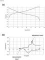
- dQ/dV represents the ratio of the amount of change dQ in the power storage amount of the battery to the amount of change dV in the voltage of the battery. That is, the processor 110 may generate V-dQ/dV illustrated in FIG. 5 by differentiating the V-Q graph (or a function corresponding to the V-Q graph) with respect to a voltage V of the battery.
- V-dQ/dV is a graph showing a relationship between the battery voltage V and dQ/dV.
- the processor 110 may detect two feature points (reference point and measurement point) on the V-dQ/dV graph.
- the processor is configured to, in reflecting the SOC information about cells in the state of balance by voltage, calculate the state of balance by voltage in which the SOC information is reflected by applying a dQ reference /dV reference value at the reference point and a dQ measurement /dV measurement value at the measurement point.
- a correction factor D may be calculated using ⁇ Equation 11> below, and SOB3 voltage may be calculated by reflecting the correction factor D.
- the dQ/dV value is the ratio of the amount of change in the capacity to the amount of change in the voltage, and by applying a dQ/dV value of a voltage measurement point compared to a specific reference point to the SOB calculation, a difference in voltage change according to SOC may be offset.
- the reference point of (dQ reference /dV reference ) may be any point within the voltage range in which the cells are driven, and preferably, any voltage point among points of 30 to 70% of SOC may be used as the reference point.
- the processor 110 may remove noise components of the V-dQ/dV graph using a noise filter prior to detecting feature points on the V-dQ/dV graph.
- a noise filter may remove noise components of the V-dQ/dV graph using a noise filter prior to detecting feature points on the V-dQ/dV graph.
- FIG. 5 shows an example in which two feature points located on a V-dQ/dV graph are detected by the processor 110.
- a tertiary state-of-balance value by voltage SOB3 voltage is calculated by reflecting the correction factor D in the primary state-of-balance value by voltage SOB1 voltage and the secondary state-of-balance value by voltage SOB2 voltage .
- the state of health of the battery SOH balance to which the state of balance by voltage of the battery is applied may be calculated using Equation 13 below.
- SOH capacity represents a lifespan based on the the remaining capacity (SOC) of the battery
- SOH balance represents a lifespan obtained by applying the state of balance by voltage to the lifespan based on the remaining capacity of the battery.
- the state of health of the battery to which a more accurate state of balance by voltage is applied may be estimated by reflecting the SOC of the cells.
- SOB 100? X dV/X Stdev N Y SO81 NO NO S0 0.0021 0.0205 18 2 64 A A SOB2 dQ/dV(re ference) dQ/dV(me asurement) SOB3 0.4583 0.4583 64.917 16.639 1.665 97.314 Cell inclusion rate by quantile section 1st section 2nd section 3rd section 4th section 5th section 6th section 7th section 8th section 9th section 10th section 0 10 15 20 30 35 40 45 60 65 11th section 12th section 13th section 14th section 15th section 16th section 17th section 18th section 19th section 20th section 70 75 80 85 85 95 95 100 100 100 100 21st section 22nd section 23rd section 24th section 25th section 26th section 27th section 28th section 29th section 30th section 100 100 100 100 100 100 100 100 100 100 100 100 100 100 100 100 100 100 100 100 100 100 100 100 100 100 100 100 100 100 100 100 100 100 100 100 100 100 100 100 100 100 100 100 100 100 100 100 100 100 100
- Tables 1 and 2 are data collected during a subsequent charging process after completely discharging all cells constituting the battery pack, and since the SOB was measured immediately after performing complete discharging, the balance would not be significantly lost, so that it may be assumed that deviation of the SOB will not be large.
- ⁇ Table 1> shows data obtained by measuring the voltage distribution of cells around 3.1 V that is an area where the voltage deviation according to the SOC is very large.
- SOB2 calculated by simply reflecting the voltage distribution and limit quantile of the cells was 64.917
- SOB3 calculated by reflecting the correction factor D for the SOC was calculated as 97.314. That is, it can be seen that there is a very large difference in the values of the SOB in which SOC information is reflected and SOB in which SOC information is not reflected.
- ⁇ Table 2> shows data obtained by measuring the voltage distribution of cells around 4.0 V that is an area where the voltage deviation according to the SOC is small.
- SOB2 was calculated as 95.295
- SOBS reflecting the correction factor D was calculated as 98.594.
Landscapes
- Physics & Mathematics (AREA)
- General Physics & Mathematics (AREA)
- Engineering & Computer Science (AREA)
- Manufacturing & Machinery (AREA)
- Chemical & Material Sciences (AREA)
- Chemical Kinetics & Catalysis (AREA)
- Electrochemistry (AREA)
- General Chemical & Material Sciences (AREA)
- Secondary Cells (AREA)
- Tests Of Electric Status Of Batteries (AREA)
- Charge And Discharge Circuits For Batteries Or The Like (AREA)
Abstract
Description
- The present invention relates to an apparatus and method capable of estimating a state of health of a battery, and more particularly, to a method for more accurately calculating a state-of-balance value by voltage by reflecting state-of-charge (SOC) information about a battery and measuring a state of health of a battery based on the state-of-balance value of the battery by voltage.
- A battery module or battery pack is a device manufactured by combining a plurality of battery cells to protect against physical shock from the external environment and perform a specific role, and is generally simply referred to as a "battery." For example, representative batteries are rechargeable batteries installed in smartphones, walkie-talkies, laptops, and the like, and in the case of high power consumption such as electric bicycles and electric vehicles, a single battery pack structure may be designed by bundling together as few as one or two to as many as dozens of batteries.
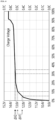
- Meanwhile, when the lifespan of a battery decreases and the battery operates in the form of a battery pack, overcharging or overdischarging of some cells occurs when the degree of voltage deviation of cells constituting the battery pack increases (
FIG. 1 ). As described above, when overcharged or overdischarged cells occur among the cells of the battery, safety is greatly reduced, which may result in a risk of leading to fire or explosion in abnormal situations. In addition, when some of the battery cells first reach an upper limit voltage or lower limit voltage, the use of the battery is limited even though there is remaining capacity, and thus there is a limitation that the entire capacity of the battery is not able to be used. - Therefore, a method has been devised to calculate a state of balance (SOB) by voltage based on the voltage distribution of the plurality of cells constituting the battery pack and calculate a state of health (SOH) based on the calculated SOB, but there is a problem in that the voltage deviation according to a state of charge (SOC) of the cells is not reflected, and thus, even though the SOB is the same, the SOB is distorted and differently calculated depending on the SOC.
-
- 1.
Korean Patent Laid-Open Publication No. 10-2016-0058281 - 2.
Korean Patent Registration No. 10-2256117 - In order to solve a first problem, the present invention provides an apparatus capable of calculating a state of balance (SOB) by voltage of cells constituting a battery pack and accurately estimating a state of health of a battery by applying the SOB calculated as above, and a method thereof.
- In order to solve a second problem, the present invention provides an apparatus capable of more accurately estimating a state of health of a battery by calculating a state of balance (SOB) by voltage by reflecting SOC information about cells constituting a battery pack when calculating the SOB of the cells, and a method thereof.
- Objects of the present invention are not limited to those mentioned above, and other objects of the present invention that are not mentioned above could be understood by the detailed description and be more clearly understood from embodiments set forth in the present invention. Further, it will be readily understood that objects and advantages of the present invention may be implemented by means set forth in the claims and combinations thereof.
- In order to achieve the objects described above, according to one aspect of the present invention, an apparatus for estimating a state of health of a battery includes a memory configured to load a program for calculating a state-of-balance value by voltage of a plurality of cells constituting a battery and estimating a state-of-health balance value that is a state-of-health value of the battery to which the state-of-balance value by voltage is applied and a processor configured to execute instructions included in the program loaded by the memory.
- In this case, the processor may be configured to, according to execution of the program, set a voltage difference allowable limit value within a voltage difference between a fully charged state voltage of the battery and a discharged state voltage thereof and set an allowable limit quantile that subdivides an allowable limit range to which the voltage difference allowable limit value is applied into one or more analysis sections based on an average voltage value derived from measured voltage values of the cells, calculate a voltage drop rate in the allowable limit range based on the average voltage value, where a quantile drop rate based on the allowable limit quantile is calculated as the voltage drop rate, derive a quantile order that is an order of an analysis section in which all measured voltage values for each cell are initially included within the allowable limit quantile, calculate the state-of-balance value by voltage by reflecting the quantile drop rate, and SOC information about the cells, the quantile order, and estimate the state-of-health balance value by applying the state-of-balance value by voltage to the state-of-health value calculated based on a remaining capacity of the battery.
- In addition, the processor may provide a user interface that allows a user to set at least one of the voltage difference allowable limit value and the allowable limit quantile.
- In addition, the processor may be configured to calculate a reference deviation voltage value that is a voltage difference per allowable limit quantile, calculate a value of a correction factor based on a standard deviation calculated based on the average voltage and the number of cells, the reference deviation voltage value, and the quantile order, calculate a secondary state-of-balance value by voltage by adding a product of the value of the correction factor and the quantile drop rate to a primary state-of-balance value by voltage that is the state-of-balance value by voltage calculated based on the quantile drop rate and the quantile order, and estimate the state-of-health balance value by applying the secondary state-of-balance value by voltage to the state-of-health value.
- In addition, when calculating the secondary state-of-balance value by voltage, the processor may be configured to change the calculated value of the correction factor to zero (0) when the value is a negative number and apply the changed value and apply the calculated value of the correction factor as it is when the value is a positive number.
- In addition, the processor may be configured to calculate the amount of power stored in the battery based on a current applied to the battery. In addition, the processor may be configured to convert a Q-V graph showing a relationship between a voltage of the battery and the power storage amount of the battery into a V-dQ/dV graph showing a relationship between the voltage of the battery and the ratio of an amount of change in the power storage amount to an amount of change in the voltage of the battery.
- Meanwhile, the processor may detect two feature points including a reference point and a measurement point from the V-dQ/dV graph.
- In addition, the processor may be configured to, in reflecting the SOC information about cells in the state of balance by voltage, calculate the state of balance by voltage in which the SOC information is reflected by applying a dQreference/dVreference value at the reference point and a dQmeasurement/dVmeasurement value at the measurement point.
- In addition, the processor may set the voltage difference allowable limit value to be greater than a value obtained by dividing a usage voltage range value that is a difference between the fully charged state voltage and the discharged state voltage by the number of the plurality of cells and smaller than a value obtained by dividing the usage voltage range value by 2.
- In addition, the processor may be configured to sequentially increase the quantile order that is a variable in integer units within a range from 1 to the allowable limit quantile, calculate a range of a value obtained by subtracting or adding a value obtained by multiplying a value obtained by dividing the voltage difference allowable limit value by the allowable limit quantile by the quantile order from or to the average voltage value, derive an initial quantile order that includes all measured voltages for each cell within the calculated range, and calculate the state-of-balance value by voltage based on the derived quantile order.
- In addition, the processor may determine that the state-of-balance value by voltage is zero (0) when all of the measured voltages for each cell are not included within the calculated range while the quantile order that is a variable is increased to the allowable limit quantile.
- Meanwhile, according to another aspect of the present invention, a method for estimating a state of health of a battery by an apparatus for estimating a state of health of a battery includes setting a voltage difference allowable limit value within a voltage difference between a fully charged state voltage of a battery including a plurality of cells and a discharged state voltage thereof, setting an allowable limit quantile that subdivides an allowable limit range to which the voltage difference allowable limit value is applied into one or more analysis sections based on an average voltage value derived from measured voltage values of the cells, calculating a voltage drop rate in the allowable limit range based on the average voltage value, where a quantile drop rate based on the allowable limit quantile is calculated as the voltage drop rate, deriving a quantile order that is an order of an analysis section in which all measured voltage values for each cell are initially included within the allowable limit quantile, determining a power storage amount of the battery based on a current applied to the battery and converting a Q-V graph showing a relationship between a voltage of the battery and the power storage amount of the battery into a V-dQ/dV graph showing a relationship between the voltage of the battery and the ratio of an amount of change in the power storage amount to an amount of change in the voltage of the battery, and calculating the state-of-balance value by voltage based on the quantile drop rate, the quantile order, and V-dQ/dV values of the feature points and estimating the state-of-health balance value by applying the state-of-balance value by voltage to the state-of-health value calculated based on a remaining capacity of the battery.
- In this case, the method for estimating a state of health of a battery may further include, prior to the setting of the voltage difference allowable limit value, providing a user interface that allows a user to set at least one of the voltage difference allowable limit value and the allowable limit quantile and receiving at least one of the voltage difference allowable limit value and the allowable limit quantile through the user interface.
- In addition, the estimating of the state-of-health balance value may include calculating a reference deviation voltage value that is a voltage difference per allowable limit quantile, calculating a value of a correction factor A based on a standard deviation calculated based on the average voltage and the number of cells, the reference deviation voltage value, and the quantile order, calculating a secondary state-of-balance value by voltage by adding a product of the value of the correction factor A and the quantile drop rate to a primary state-of-balance value by voltage that is the state-of-balance value by voltage calculated based on the quantile drop rate and the quantile order, calculating the dQ/dV value of the reference point and the dQ/dV value of the measurement point based on the V-dQ/dV graph and calculating a correction factor D by dividing the dQ/dV value of the measurement point by the dQ/dV value of the reference point, calculating a tertiary state-of-balance value by voltage by reflecting the correction factor D, and estimating the state-of-health balance value by applying the tertiary state-of-balance value by voltage to the state-of-health value.
- The solution to the above problem does not enumerate all the features of the present invention. The various features of the present invention and its advantages and effects may be understood in more detail by referring to the specific examples below.
- According to one embodiment of the present invention, it is possible to more accurately manage a state of balance by voltage between cells of a battery constituting a battery pack by reflecting SOC information about the cells, and possible to predict and take action in advance before a battery in which the state of balance by voltage of the cells is broken reaches a dangerous situation.
- In addition to the above effects, specific effects of the present invention will be described together while describing specific details for carrying out the present invention.
-
-
FIG. 1 is one example of a graph showing a deviation in capacity of cells according to battery use. -
FIG. 2 is a configuration diagram of an apparatus for estimating a state of health of a battery according to one embodiment of the present invention. -
FIG. 3 is a flowchart for describing a method for estimating a state of health of a battery based on a state of balance by voltage according to one embodiment of the present invention. -
FIG. 4 is one example of a graph for describing a voltage deviation according to an SOC of cells. -
FIG. 5 is a graph illustrating a V-dQ/dV graph (b) obtained from a Q-V graph (a). -
FIG. 6 is one example of a graph for describing a method for estimating a state of health of a battery reflecting a state of balance by voltage of cells according to one embodiment of the present invention. - Hereinafter, principles of preferred embodiments of the present invention will be described in detail with reference to the accompanying drawings and description. However, the drawings shown below and the description below are for preferred implementation methods among various methods for effectively describing features of the present invention, and the present invention is not limited to the drawings and description below.
- Meanwhile, terms such as first or second may be used to describe various elements, but the terms are to be interpreted only for the purpose of distinguishing one element from another element. For example, a first element may be termed a second element, and similarly, a second element may also be termed a first element.
- The singular forms, "a", "an", and "the" are intended to include the plural forms as well, unless the context clearly indicates otherwise. In the present specification, it should be understood that the terms "includes" and/or "including" specify the presence of described features, integers, steps, operations, elements, components, and/or groups thereof, but do not preclude the presence or addition of one or more other features, integers, steps, operations, elements, components, and/or groups thereof.
- Unless otherwise defined, all terms used herein, including technical or scientific terms, have the same meaning as commonly understood by those of ordinary skill in the art. Terms, such as those defined in commonly used dictionaries, should be interpreted as having a meaning that is consistent with their meaning in the context of the related art and will not be interpreted in an idealized or overly formal sense unless expressly so defined herein.
- In the following, a process for estimating a state of health of a battery according to one embodiment of the present invention will be described with reference to the attached drawings.
- First,
FIG. 2 is a configuration diagram of an apparatus for estimating a state of health of a battery according to one embodiment of the present invention. - A battery state-of-
health estimation apparatus 100 shown inFIG. 2 may be a computing device that operates by at least one processor. Further, the battery state-of-health estimation apparatus 100 may execute a program containing instructions described to execute operations according to the present invention. - The
apparatus 100 may be included in a battery management system (BMS) (not shown) provided in a battery pack. - As shown in
FIG. 2 , the hardware of the battery state-of-health estimation apparatus 100 may include at least oneprocessor 110,memory 120,storage 130, andcommunication interface 140, and each component may be connected via a bus. - In addition, the battery state-of-
health estimation apparatus 100 may further include hardware such as a separate input device, an output device, or the like. - In addition, the battery state-of-
health estimation apparatus 100 may be equipped with various software, including an operating system capable of running programs, on a storage device such as thestorage 130. - The
processor 110 is a device that controls the operation of thecomputing device 100, and may be various types of processors (e.g., a central processing unit (CPU), a micro processor unit (MPU), a micro controller unit (MCU), a graphic processing unit (GPU), and the like) that process instructions included in programs. - The
memory 120 may load a corresponding program so that instructions described to execute operations according to the present invention are processed by theprocessor 110. For example, thememory 120 may be a read only memory (ROM), a random access memory (RAM), or the like. - The
storage 130 may store various data and programs required to execute operations according to the present invention. In this case, thestorage 130 may store result data processed according to the execution of the program and measurement data input through a previously linked or connected device (e.g., a battery management system (BMS) or the like) by matching them for each battery and forming a database. - The
communication interface 140 may be a wired/wireless communication module that handles communication between respective components of thecomputing device 100 and communication with externally linked devices. -
FIG. 3 is a flowchart illustrating a process in which the battery state-of-health estimation apparatus according to one embodiment of the present invention estimates an accurate state of health of a battery based on a state of balance by voltage of battery cells. In addition,FIG. 4 is one example of a graph for describing a voltage deviation according to an SOC of a battery. - The battery state-of-
health estimation apparatus 100 according to an embodiment of the present invention may calculate the state of balance by voltage SOBvoltage between the battery cells by reflecting SOC information and calculate the state-of-health balance SOHbalance by applying the state of balance by voltage SOBvoltage of battery cells to a reference state of health SOHcapacity according to a thermodynamic standard capacity (that is, the state of charge (SOC)) for the battery. - In a battery including a plurality of single cells (that is, cells), the state of balance by voltage (SOB) is a factor indicating the degree of voltage equalization of the single cells. That is, the state of balance by voltage (SOB) is a value that allows checking how much a voltage state of each single cell of the battery differs from an average voltage at any given point in time.
- By calculating the state-of-health balance SOHbalance, to which the actual state of balance by voltage between the single cells is applied, it is possible to estimate the accurate state of health of the battery under actual use environments. That is, whereas in the related art, estimating the state of health of the battery is limited to information such as the average voltage value and the standard deviation of cells, the method for estimating a state of health of a battery according to one embodiment of the present invention may estimate the state of health of the battery by applying even whether the state of balance by voltage between battery cells is at a level that allows stable battery operation and the SOC information about the cells.
- In this regard, the SOB in the related art is calculated through the voltage distribution of cells at an arbitrary point in time, that is, voltage distribution information such as the average voltage and standard deviation of the voltage of the cells constituting the battery pack. However, even when the charge amount deviation of the cells constituting the battery pack shows the same distribution, the voltage deviation may significantly differ depending on the arbitrary point in time at which the voltage is measured, that is, the arbitrary SOC, and thus in some cases, the SOB may be measured in a distorted manner.
- For example, in an SOC-voltage curve of
FIG. 4 showing the SOC and voltage of cells, looking at the change in voltage according to the state of charge, it can be seen that a difference between a voltage difference (△V1) of 5% and 10% of SOC and a voltage difference (△V2) of 30% and 35% of SOC is very large. The charged capacity difference (SOC difference) of the cells constituting the battery pack is the same, but the voltage distribution of the cells varies greatly depending on the SOC for which the battery voltage is measured. - That is, assuming that there is a battery pack including two cells, a pack with one cell of 5% of SOC and one
cell 10% of SOC, and a pack with one cell of 35% of SOC and one cell of 40% of SOC differ only in the SOC at the time of measurement, but severe distortion occurs in the voltage deviation. Accordingly, in the present invention, the present inventors have made much effort to supplement the method for calculating SOB only through the voltage distribution in the related art, and have arrived at the present invention. - Meanwhile, referring to
FIG. 3 , theprocessor 110 may process the following operations by executing a series of instructions included in the program, and in this way, the state-of-health balance SOHbalance of the battery in which the state of balance by voltage of the battery cell is reflected may be estimated and output. - First, values of preset parameters are derived based on basic information and actual measurement information in information for each battery stored in the
storage 140. - In this case, the preset parameters may include a "fully charged state voltage Vcha" applied to the single cells of the battery, a "discharged state voltage Vdis" applied to the single cells of the battery, a "maximum voltage Vmax" among measured voltages of each of the single cells of the battery, a "minimum voltage Vmin" among the measured voltages of each of the single cells of the battery, an "average voltage Vavg" for the measured voltages of the single cells of the battery, the "number n" of the single cells constituting the battery, a maximum "operating voltage range Vf" of the battery, and a "voltage standard deviation σn" for the single cells of the battery.
- Specifically, the voltage range at which the battery is able to be used, that is, the maximum operating voltage range Vf, may be defined as
Equation 1 below. -

- As described above, Vcha is the fully charged state voltage of the single cells constituting the battery, and Vdis is the discharged state voltage of the single cells. That is, a difference between the maximum charge voltage and maximum discharge voltage of the battery may be defined as the voltage range value Vf in which the battery is capable of being used.
- The battery usage voltage range Vf defined as above is calculated.
- For example, referring to
FIG. 6 , when the fully charged state voltage Vcha is set to 4.2 V and the discharged state voltage Vdis is set to 3.0 V in any lithium ion battery, the usage voltage range Vf may be calculated as 1.2 V. - In order to estimate the state of balance by voltage SOB of the single cells of the corresponding battery based on each parameter derived in this way, the following two parameters dV and X are determined.
- A maximum allowable voltage difference between the single cells within the previously determined usage voltage range Vf, that is, a voltage difference allowable limit dV, is determined. The voltage difference allowable limit dV is a parameter that may be specified by a user to set an appropriate range of the state of balance by voltage (SOB), and the value of the range is not limited.
- In this case, the
processor 110 may provide a user interface that allows a user (e.g., a battery examiner, battery use system designer, or the like) to select the voltage difference allowable limit dV. The user interface provided through theprocessor 110 is a concept that includes a graphical user interface (GUI). - In this way, the value of the voltage difference allowable limit dV may be input in real time or in advance through the user interface provided by the
processor 110, and this user interface may include recommended values of the voltage difference allowable limit dV, allowing the user to select a dV value suitable for the desired state of balance by voltage of the cells of the battery among the recommended dVs. - The voltage difference allowable limit dV may be determined according to the conditions of
Equation 2 below. -

- That is, the voltage difference allowable limit dV between the single cells of the battery may be set to be greater than or equal to a value obtained by dividing the usage voltage range Vf by the number of single cells n, but not more than 0.5 times the usage voltage range.
- In the case of the lithium ion battery according to the example in
FIG. 6 , it is shown that the usage voltage range Vf is 1.2 V, and the value of the voltage difference allowable limit dV is determined to be "1.2 V/2=0.6 V", which is the maximum value in the voltage difference allowable limit range. InFIG. 6 , it is shown as an example that dV is the maximum value of Vf/2, but dV is not limited thereto, and the narrower the allowable limit range to which dV is applied based on the average voltage Vavg is set, the greater the efficiency of applying the state of balance by voltage may be. - Referring to
FIG. 6 , the average voltage Vavg derived from the measured voltage of the single cells is 3.6 V, and voltage difference ranges from the average voltage Vavg to 0.6 V in a negative direction and 0.6 V in the positive direction, respectively, may be determined as the allowable limit range. - Next, in order to determine a balance precision of the distribution within the voltage difference allowable limit range, an allowable limit quantile X, which is the number of analysis sections within the voltage difference allowable limit range, is determined.
- For example, the allowable limit quantile X may be determined according to conditions of
Equation 3 below. -

- As in
Equation 3, the allowable limit quantile X may be set to a number greater than or equal to 3 and less than or equal to 2nd power of the number n of the single cells. - In this case, the
processor 110 may provide a user interface that allows the user (e.g., the battery examiner, battery use system designer, or the like) to select the number of allowable limit quantiles X. - The user interface provided through the
processor 110 is a concept that includes a graphical user interface (GUI). In this way, the value of the allowable limit quantile X may be input in real time or in advance through the user interface provided by theprocessor 110, and this user interface may include recommended values of the allowable limit quantile X, allowing the user to select an X value suitable for the desired precision of the battery among the recommended Xs. - In this way, in a state in which the voltage difference allowable limit range dV and the allowable limit quantile X are determined, a quantile drop rate Y is determined. The quantile drop rate Y refers to a voltage drop rate in the allowable limit range based on the average voltage. For example, the quantile drop rate Y may be defined as
Equation 4 below. -

- In the lithium ion battery according to the example of
FIG. 6 , when the allowable limit quantile X is determined to be 25, the quantile drop rate Y is 4. - In addition, in the lithium ion battery according to the example in
FIG. 6 , since the usage voltage range Vf is 1.2 V and the voltage difference allowable limit dV is 0.6 V, a reference deviation voltage dV/X, which refers to the voltage difference per allowable limit quantile, may be calculated as "0.6/25 = 0.024." - Then, the average voltage Vavg and standard deviation on are calculated based on the measured voltage value Vcell of each of the single cells V1 to Vn of the battery.
- For example, the standard deviation on may be calculated using
Equation 5 below. -

- In the lithium ion battery according to the example of
FIG. 6 , since the average voltage Vavg calculated based on the measured voltage Vcell measured for each cell (that is, the single cell) is 3.6 V, the standard deviation on may be calculated as 0.187. - Next, a quantile order N, which includes all voltage values of each measured cell, is calculated. The quantile order N refers to an integer that increases sequentially from 1 to the allowable limit quantile X.
- In this case, the quantile order N may be determined using Equation 6 below.
-

- As in Equation 6, the quantile order N may be determined based on the average voltage value Vavg of the single cells and the reference deviation voltage dV/X.
- In the lithium ion battery according to the example in
FIG. 6 , when the average voltage Vavg is 3.6 V and the reference deviation voltage dV/X is 0.024, the first quantile order N, which includes the measured voltages of all cells, may be 5. - Specifically, an initial quantile order N, which includes the voltage values of all individual cells (that is, single cells), may be obtained by calculating the number of Vcells satisfying conditions in Equation 7 below when the quantile order N, which is a variable, is sequentially increased in integer units from 1 to X.
-

- When a result in Equation 6 above is expressed as a percentage of n, the quantile order N that initially becomes 100 (that is, the measured voltages of all single cells are included in the range) may be derived. That is, while dividing the quantiles by increasing the quantile order N by 1, the initial quantile order N that includes the measured voltages of all single cells within the range from the average voltage Vavg to the determined allowable limit dV is determined.
- Next, the state-of-balance value by voltage SOBvoltage for the single cells is calculated based on the quantile order N calculated through Equations 6 and 7 above.
- SOB1voltage, which is the primary state-of-balance value by voltage, may be calculated using Equation 8 below.
-

- For reference, when the quantile order N that initially becomes 100 is not found, when expressed as a percentage of n until the quantile order N, which is a variable, becomes X, SOB1voltage is determined to be 0.
- On the other hand, when the quantile order N that initially becomes 100 is any one of 1 to X when expressed as a percentage of n until the quantile order N, which is a variable, becomes X, SOB1voltage is calculated as 100 - Y*N as in Equation 8, and Y=100/X.
- In the lithium ion battery according to the example in
FIG. 6 , since the quantile order N is 5 and Y is 4, SOB1voltage is calculated as 80 by "100 - 4*5." - Meanwhile, an intra-quantile balance correction factor A may be calculated from the standard deviation σn and the reference deviation voltage dV/X, and a secondary state-of-balance value by voltage SOB2voltage may be calculated using the correction factor A.
- The correction factor A may be obtained using Equation 9 below, and the secondary state-of-balance value by voltage SOB2voltage may be obtained using
Equation 10. -

- The correction factor A is a balance correction factor of each quantile.
- In the lithium ion battery according to the example in
FIG. 6 , since the quantile order N is 5, the reference deviation voltage dV/X is 0.024, and the standard deviation σn is 0.02, the correction factor A is determined to be 0.83 by "(5*0.024 - 0.02)/(5*0.024)."
- As in
Equation 10, the secondary state-of-balance value by voltage SOB2voltage is calculated based on the product of the primary state-of-balance value by voltage SOB1voltage, the correction factor A, and quantile drop rate Y. In this case, when the correction factor A is negative, A' is set to 0, and when the A value is positive, A' is set to the A value. - In the lithium ion battery according to the example in
FIG. 6 , since the correction factor A is a positive number of 0.83, A' is set to 0.83, and as a result, the secondary state-of-balance value by voltage SOB2voltage is determined to be "83.32" by "80 + 0.83*4." - Meanwhile, SOB1voltage and SOB2voltage reflect the voltage distribution of the cells constituting the battery pack, but as described above, do not reflect the SOC information at the time of measuring SOB, so even when the cells show the same distribution of the charge amount, depending on the measured SOC, the voltage difference between the cells is large, so that SOB may be differently calculated.
- Therefore, it is necessary to calculate the state-of-balance value by voltage SOB3voltage by reflecting the SOC information about the cells constituting the battery pack.
- Referring to
FIG. 5 , theprocessor 110 converts a V-Q graph (or a function corresponding to the V-Q graph) of the battery into a V-dQ/dV graph. Here, dQ/dV represents the ratio of the amount of change dQ in the power storage amount of the battery to the amount of change dV in the voltage of the battery. That is, theprocessor 110 may generate V-dQ/dV illustrated inFIG. 5 by differentiating the V-Q graph (or a function corresponding to the V-Q graph) with respect to a voltage V of the battery. V-dQ/dV is a graph showing a relationship between the battery voltage V and dQ/dV. - Next, the
processor 110 may detect two feature points (reference point and measurement point) on the V-dQ/dV graph. In addition, the processor is configured to, in reflecting the SOC information about cells in the state of balance by voltage, calculate the state of balance by voltage in which the SOC information is reflected by applying a dQreference/dVreference value at the reference point and a dQmeasurement/dVmeasurement value at the measurement point. - Here, for SOB3voltage to reflect the voltage change according to SOC, a correction factor D may be calculated using<Equation 11> below, and SOB3voltage may be calculated by reflecting the correction factor D.
- Here, the dQ/dV value is the ratio of the amount of change in the capacity to the amount of change in the voltage, and by applying a dQ/dV value of a voltage measurement point compared to a specific reference point to the SOB calculation, a difference in voltage change according to SOC may be offset.
-

- In this case, the reference point of (dQreference/dVreference) may be any point within the voltage range in which the cells are driven, and preferably, any voltage point among points of 30 to 70% of SOC may be used as the reference point.
- In this case, since (dQreference/dVreference) calculated from the same reference point is applied within the same cell or the same battery, even when (dQreference/dVreference) is measured at an arbitrary point, relative SOB may be calculated within the same cell or same battery.
- Meanwhile, the
processor 110 may remove noise components of the V-dQ/dV graph using a noise filter prior to detecting feature points on the V-dQ/dV graph. By preventing the phenomenon of misdetecting feature points from the V-dQ/dV graph ofFIG. 5 due to the noise component present in V-dQ/dV ofFIG. 3 , the accuracy of feature point detection may be improved. Of course, smoothing the V-dQ/dV graph is an optional process. -
FIG. 5 shows an example in which two feature points located on a V-dQ/dV graph are detected by theprocessor 110. - In addition, as shown in Equation 12 below, a tertiary state-of-balance value by voltage SOB3voltage is calculated by reflecting the correction factor D in the primary state-of-balance value by voltage SOB1voltage and the secondary state-of-balance value by voltage SOB2voltage.
-

- Next, by correcting the state of health SOH of the battery using the tertiary state-of-balance value by voltage SOB3voltage, the state-of-health balance SOHbalance to which the state of balance by voltage is applied is calculated.
- The state of health of the battery SOHbalance to which the state of balance by voltage of the battery is applied may be calculated using Equation 13 below.
-

- In this case, SOHcapacity represents a lifespan based on the the remaining capacity (SOC) of the battery, and SOHbalance represents a lifespan obtained by applying the state of balance by voltage to the lifespan based on the remaining capacity of the battery.
- As described above, since the average value, standard deviation, and limit quantile alone may not accurately express the state of balance of the cells of the battery, the state of health of the battery to which a more accurate state of balance by voltage is applied may be estimated by reflecting the SOC of the cells.
- Referring to Table 1 and Table 2 below, let's look at the state of battery by voltage SOB of the battery. Table 1 and Table 2 below are measurements using the same battery, and the SOB is calculated at different voltage bands after completely discharging.
<Table 1> Single cell measurement voltage V(1) V(2) V(3) V(4) V(5) V(6) V(7) V(8) V(9) V(10) 3.133 3.120 3.122 3.072 3.121 3.114 3.114 3.124 3.116 3.122 V(11) V(12) V(13) V(14) V(15) V(16) V(17) V(18) V(19) V(20) 3.130 3.093 3.101 3.071 3.096 3.079 3.081 3.067 3.091 3.108 Various parameters n Vcha Vdis Vf Vmax Vmin Vavg dv Vmax-Vavg Vavg- Vmin 20 4.15 3.1 1.05 3.133 3.067 3.104 0.105 0.066 0.037 SOB=0? SOB=100? X dV/X Stdev N Y SO81 NO NO S0 0.0021 0.0205 18 2 64 A A SOB2 dQ/dV(re ference) dQ/dV(me asurement) SOB3 0.4583 0.4583 64.917 16.639 1.665 97.314 Cell inclusion rate by quantile section 1st section 2nd section 3rd section 4th section 5th section 6th section 7th section 8th section 9th section 10th section 0 10 15 20 30 35 40 45 60 65 11th section 12th section 13th section 14th section 15th section 16th section 17th section 18th section 19th section 20th section 70 75 80 85 85 95 95 100 100 100 21st section 22nd section 23rd section 24th section 25th section 26th section 27th section 28th section 29th section 30th section 100 100 100 100 100 100 100 100 100 100 31st section 32nd section 33rd section 34th section 35th section 36th section 37th section 38th section 39th section 40th section 100 100 100 100 100 100 100 100 100 100 41st section 42nd section 43rd section 44th section 45th section 46th section 47th section 48th section 49th section 50th section 100 100 100 100 100 100 100 100 100 100 <Table 2> V(1) V(2) V(3) V(4) V(5) V(6) V(7) V(8) V(9) V(10) 3.996 3.997 3.997 3.997 3.995 3.997 3.997 3.997 3.998 4.001 V(11) V(12) V(13) V(14) V(15) V(16) V(17) V(18) V(19) V(20) 4.001 3.999 3.998 4.000 3.998 3.997 3.997 3.997 4.003 4.004 Various parameters n Vcha Vdis Vf Vmax Vmin Vavg dv Vmax-Vavg Vavg-Vmin 20 4.15 3.1 1.05 4.004 3.996 3.998 0.105 0.008 0.002 SOB=0? SOB=100? X dV/X Stdev N Y SO81 NO NO S0 0.0021 0.00222 3 2 94 A A' SOB2 dQ/dV(refer ence) dQ/dV(me asurement) SOB3 0.6477 0.6477 95.295 16.639 7.492 98.594 Cell inclusion rate by quantile section 1st section 2nd section 3rd section 4th section 5th section 6th section 7th section 8th section 9th section 10th section 80 90 100 100 100 100 100 100 100 100 11th section 12th section 13th section 14th section 15th section 16th section 17th section 18th section 19th section 20th section 100 100 100 100 100 100 100 100 100 100 21st section 22nd section 23rd section 24th section 25th section 26th section 27th section 28th section 29th section 30th section 100 100 100 100 100 100 100 100 100 100 31st section 32nd section 33rd section 34th section 35th section 36th section 37th section 38th section 39th section 40th section 100 100 100 100 100 100 100 100 100 100 41st section 42nd section 43rd section 44th section 45th section 46th section 47th section 48th section 49th section 50th section 100 100 100 100 100 100 100 100 100 100 - Tables 1 and 2 are data collected during a subsequent charging process after completely discharging all cells constituting the battery pack, and since the SOB was measured immediately after performing complete discharging, the balance would not be significantly lost, so that it may be assumed that deviation of the SOB will not be large.
- <Table 1> shows data obtained by measuring the voltage distribution of cells around 3.1 V that is an area where the voltage deviation according to the SOC is very large. In this case, SOB2 calculated by simply reflecting the voltage distribution and limit quantile of the cells was 64.917, but SOB3 calculated by reflecting the correction factor D for the SOC was calculated as 97.314. That is, it can be seen that there is a very large difference in the values of the SOB in which SOC information is reflected and SOB in which SOC information is not reflected.
- On the other hand, <Table 2> shows data obtained by measuring the voltage distribution of cells around 4.0 V that is an area where the voltage deviation according to the SOC is small. Here, SOB2 was calculated as 95.295, and SOBS reflecting the correction factor D, was calculated as 98.594.
- Although it is assumed that the SOBs are similar SOBs in this way, it can be seen that the difference between the calculated SOBs is very large depending on the measuring point in time, and it can be seen that when the SOB is calculated by reflecting the correction factor D, more accurate measurement is possible.
- Although the preferred embodiments of the present invention have been described in detail above, the scope of the present invention is not limited thereto, and various modifications and improvements made by those skilled in the art using the basic concept of the present invention defined in the following claims also fall within the scope of the present invention.
- 100:
- Battery state-of-health estimation apparatus
- 110:
- Processor
- 120:
- Memory
- 130:
- Storage
- 140:
- Communication interface.
Claims (6)
- An apparatus for estimating a state of health of a battery, the apparatus comprising:a memory configured to load a program for calculating a state-of-balance value by voltage of a plurality of cells constituting a battery and estimating a state-of-health balance value that is a state-of-health value of the battery to which the state-of-balance value by voltage is applied; anda processor configured to execute instructions included in the program loaded by the memory,wherein the processor is configured to, according to execution of the program:set a voltage difference allowable limit value within a voltage difference between a fully charged state voltage of the battery and a discharged state voltage thereof and set an allowable limit quantile that subdivides an allowable limit range to which the voltage difference allowable limit value is applied into one or more analysis sections based on an average voltage value derived from measured voltage values of the cells;calculate a quantile drop rate that is a voltage drop rate in the allowable limit range based on the average voltage value, wherein a quantile order that is an order of an analysis section in which all measured voltage values for each cell are initially included within the allowable limit quantile is derived;determine a power storage amount of the battery based on a current applied to the battery and convert a Q-V graph showing a relationship between a voltage of the battery and the power storage amount of the battery into a V-dQ/dV graph showing a relationship between the voltage of the battery and the ratio of an amount of change in the power storage amount to an amount of change in the voltage of the battery;detect feature points including a reference point and a measurement point from the V-dQ/dV graph; andcalculate the state-of-balance value by voltage based on the quantile drop rate, the quantile order, and dQ/dV values of the feature points and estimate the state-of-health balance value by applying the state-of-balance value by voltage to the state-of-health value calculated based on a remaining capacity of the battery, andthe quantile drop rate is calculated using the following equation;
 where Y is the quantile drop rate of the battery meaning the voltage drop rate in the allowable limit range based on the average voltage and X is the allowable limit quantile.
 - The apparatus of claim 1, wherein the processor is configured to:calculate a reference deviation voltage value that is a voltage difference per allowable limit quantile;calculate a value of a correction factor A based on a standard deviation calculated based on the average voltage and the number of cells, the reference deviation voltage value, and the quantile order;calculate a secondary state-of-balance value by voltage by adding a product of the value of the correction factor and the quantile drop rate to a primary state-of-balance value by voltage that is the state-of-balance value by voltage calculated based on the quantile drop rate and the quantile order;calculate the dQ/dV value of the reference point and the dQ/dV value of the measurement point based on the V-dQ/dV graph;calculate a correction factor D by dividing the dQ/dV value of the measurement point by the dQ/dV value of the reference point;calculate a tertiary state-of-balance value by voltage by reflecting the correction factor D; andestimate the the state-of-health balance value by applying the tertiary state-of-balance value by voltage to the state-of-health value.
- The apparatus of claim 2, wherein when calculating the secondary state-of-balance value by voltage, the processor changes the calculated value of the correction factor A to zero (0) when the value is a negative number and applies the changed value and applies the calculated value of the correction factor A as it is when the value is a positive number.
- The apparatus of claim 1, wherein the processor sets the voltage difference allowable limit value to be greater than a value obtained by dividing a usage voltage range value that is a difference between the fully charged state voltage and the discharged state voltage by the number of the plurality of cells and smaller than a value obtained by dividing the usage voltage range value by 2.
- A method for estimating a state of health of a battery by an apparatus for estimating a state of health of a battery, the method comprising:setting a voltage difference allowable limit value within a voltage difference between a fully charged state voltage of a battery including a plurality of cells and a discharged state voltage thereof;setting an allowable limit quantile that subdivides an allowable limit range to which the voltage difference allowable limit value is applied into one or more analysis sections based on an average voltage value derived from measured voltage values of the cells;calculating a quantile drop rate that is a voltage drop rate in the allowable limit range based on the average voltage value, based on the allowable limit quantile;deriving a quantile order that is an order of an analysis section in which all measured voltage values for each cell are initially included within the allowable limit quantile;determining a power storage amount of the battery based on a current applied to the battery and converting a Q-V graph showing a relationship between a voltage of the battery and the power storage amount of the battery into a V-dQ/dV graph showing a relationship between the voltage of the battery and the ratio of an amount of change in the power storage amount to an amount of change in the voltage of the battery;detecting feature points including a reference point and a measurement point from the V-dQ/dV graph; andcalculating the state-of-balance value by voltage based on the quantile drop rate, the quantile order, and dQ/dV values of the feature points and estimating the state-of-health balance value by applying the state-of-balance value by voltage to the state-of-health value calculated based on a remaining capacity of the battery;
 where Y is the quantile drop rate of the battery meaning the voltage drop rate in the allowable limit range based on the average voltage and X is the allowable limit quantile.
 - The method of claim 5, wherein the estimating of the state-of-health balance value includes:calculating a reference deviation voltage value that is a voltage difference per allowable limit quantile;calculating a value of a correction factor A based on a standard deviation calculated based on the average voltage and the number of cells, the reference deviation voltage value, and the quantile order;calculating a secondary state-of-balance value by voltage by adding a product of the value of the correction factor and the quantile drop rate to a primary state-of-balance value by voltage that is the state-of-balance value by voltage calculated based on the quantile drop rate and the quantile order;calculating the dQ/dV value of the reference point and the dQ/dV value of the measurement point based on the V-dQ/dV graph and calculating a correction factor D by dividing the dQ/dV value of the measurement point by the dQ/dV value of the reference point;calculating a tertiary state-of-balance value by voltage by reflecting the correction factor D; andestimating the the state-of-health balance value by applying the tertiary state-of-balance value by voltage to the state-of-health value.
Applications Claiming Priority (2)
| Application Number | Priority Date | Filing Date | Title |
|---|---|---|---|
| KR1020220015884A KR102692385B1 (en) | 2022-02-08 | 2022-02-08 | Battery life state estimation device and method |
| PCT/KR2022/019484 WO2023153602A1 (en) | 2022-02-08 | 2022-12-02 | Apparatus and method for estimating battery state of health |
Publications (2)
| Publication Number | Publication Date |
|---|---|
| EP4478069A1 true EP4478069A1 (en) | 2024-12-18 |
| EP4478069A4 EP4478069A4 (en) | 2025-06-18 |
Family
ID=87564451
Family Applications (1)
| Application Number | Title | Priority Date | Filing Date |
|---|---|---|---|
| EP22926199.5A Pending EP4478069A4 (en) | 2022-02-08 | 2022-12-02 | Apparatus and method for estimating battery state of health |
Country Status (6)
| Country | Link |
|---|---|
| US (1) | US20250147114A1 (en) |
| EP (1) | EP4478069A4 (en) |
| JP (1) | JP7831880B2 (en) |
| KR (1) | KR102692385B1 (en) |
| CN (1) | CN118647883A (en) |
| WO (1) | WO2023153602A1 (en) |
Families Citing this family (6)
| Publication number | Priority date | Publication date | Assignee | Title |
|---|---|---|---|---|
| JP7819161B2 (en) * | 2023-09-07 | 2026-02-24 | 株式会社東芝 | Information processing device, information processing method, information processing program, and information processing system |
| KR102704715B1 (en) * | 2023-09-26 | 2024-09-06 | 이중휘 | Apparatus and method for diagnosis of residual perfomance of batteries and computer program for the same |
| CN118914900B (en) * | 2024-07-19 | 2025-03-07 | 惠州市德赛智储科技有限公司 | Battery PACK inconsistency analysis correction prediction method, system and storage medium |
| KR20260023694A (en) * | 2024-08-12 | 2026-02-20 | 주식회사 엘지에너지솔루션 | Method for diagnosing batteries and apparatus using the method |
| KR20260050677A (en) * | 2024-10-08 | 2026-04-15 | 주식회사 엘지에너지솔루션 | Electronic apparatus, recording medium and method of diagnosing abnormalities of battery cell |
| KR102881616B1 (en) | 2025-05-22 | 2025-11-13 | 주식회사 민테크 | Battery life state estimation device and method |
Family Cites Families (11)
| Publication number | Priority date | Publication date | Assignee | Title |
|---|---|---|---|---|
| JP2001223033A (en) * | 2000-02-07 | 2001-08-17 | Hitachi Ltd | Battery system and battery state detection method |
| JP5662968B2 (en) * | 2012-06-19 | 2015-02-04 | 株式会社日立製作所 | Secondary battery inspection system, charger / discharger, and inspection method |
| JPWO2015072061A1 (en) * | 2013-11-13 | 2017-03-16 | パナソニックIpマネジメント株式会社 | Equalization processing device |
| KR102156866B1 (en) | 2014-11-14 | 2020-09-17 | 한국전기연구원 | Apparatus for forecasting life cycle of battery based on AC impedance by using very low current |
| JP6172176B2 (en) * | 2015-02-09 | 2017-08-02 | トヨタ自動車株式会社 | Battery monitoring device |
| JP6380417B2 (en) * | 2016-01-21 | 2018-08-29 | 横河電機株式会社 | Secondary battery capacity measuring system and secondary battery capacity measuring method |
| JP6477957B2 (en) * | 2017-07-19 | 2019-03-06 | 株式会社Gsユアサ | Estimation device, power storage device, estimation method, and computer program |
| US12216170B2 (en) * | 2019-11-29 | 2025-02-04 | Mintech Co., Ltd | Device and method for estimating state of battery |
| KR102256117B1 (en) | 2019-11-29 | 2021-05-26 | 주식회사 민테크 | Apparatus and method to estimate state-of-health for battery |
| WO2021186511A1 (en) * | 2020-03-16 | 2021-09-23 | Tdk株式会社 | Secondary battery control device, battery pack, and secondary battery control method |
| CN114801883B (en) * | 2022-05-19 | 2025-03-14 | 孚能科技(赣州)股份有限公司 | Battery balancing control method, system, storage medium, electronic device and vehicle |
-
2022
- 2022-02-08 KR KR1020220015884A patent/KR102692385B1/en active Active
- 2022-12-02 EP EP22926199.5A patent/EP4478069A4/en active Pending
- 2022-12-02 US US18/836,853 patent/US20250147114A1/en active Pending
- 2022-12-02 CN CN202280089739.7A patent/CN118647883A/en active Pending
- 2022-12-02 JP JP2024547272A patent/JP7831880B2/en active Active
- 2022-12-02 WO PCT/KR2022/019484 patent/WO2023153602A1/en not_active Ceased
Also Published As
| Publication number | Publication date |
|---|---|
| JP2025507351A (en) | 2025-03-18 |
| US20250147114A1 (en) | 2025-05-08 |
| CN118647883A (en) | 2024-09-13 |
| JP7831880B2 (en) | 2026-03-17 |
| KR20230119756A (en) | 2023-08-16 |
| EP4478069A4 (en) | 2025-06-18 |
| KR102692385B1 (en) | 2024-08-06 |
| WO2023153602A1 (en) | 2023-08-17 |
Similar Documents
| Publication | Publication Date | Title |
|---|---|---|
| EP4478069A1 (en) | Apparatus and method for estimating battery state of health | |
| EP3916411B1 (en) | Device and method for estimating state of battery | |
| EP1384086B1 (en) | Method for determining state of charge of a battery by measuring its open circuit voltage | |
| EP3078073B1 (en) | Device and method for controlling a plurality of cells of a battery | |
| KR102281384B1 (en) | Apparatus and method to estimate state-of-charge for battery | |
| JP2023515057A (en) | Battery condition diagnosis device and method | |
| EP2915210B1 (en) | Enhanced battery management system | |
| US11307263B2 (en) | Device and method for predicting state-of-health of battery | |
| US10564223B2 (en) | Power storage system, control system of secondary battery, and control method of secondary battery | |
| CN109273787B (en) | A method and device for adjusting the state of charge SOC of a series-connected lithium-ion battery pack | |
| JP6655801B2 (en) | Lithium ion secondary battery life estimation device | |
| CN108663634B (en) | Method and device for determining internal resistance of power battery | |
| EP3605123B1 (en) | Storage battery control device and control method | |
| KR20190043457A (en) | Apparatus and methof for determining of battery health | |
| US11300627B2 (en) | Method for determining battery state of lithium ion secondary battery | |
| KR102256117B1 (en) | Apparatus and method to estimate state-of-health for battery | |
| Fan et al. | Model order reduction of electrochemical batteries using Galerkin method | |
| CN104272127A (en) | Method for determining an overall loss of capacitance of a secondary cell | |
| CN117471324A (en) | Method and device for evaluating consistency of single capacity in battery module | |
| US12322988B2 (en) | Device and method for achieving dynamic charging and balance of battery cells and rechargeable battery device | |
| KR102881616B1 (en) | Battery life state estimation device and method | |
| EP4636419A1 (en) | Battery characteristic detection device and method | |
| Garcia-Plaza et al. | State of charge estimation model for Ni-Cd batteries considering capacity and efficiency | |
| KR20250039078A (en) | Apparatus and method for estimating battery's state of charge | |
| KR100322687B1 (en) | Method for estimating capacity of battery loaded in mobile phone |
Legal Events
| Date | Code | Title | Description |
|---|---|---|---|
| STAA | Information on the status of an ep patent application or granted ep patent |
Free format text: STATUS: THE INTERNATIONAL PUBLICATION HAS BEEN MADE |
|
| PUAI | Public reference made under article 153(3) epc to a published international application that has entered the european phase |
Free format text: ORIGINAL CODE: 0009012 |
|
| STAA | Information on the status of an ep patent application or granted ep patent |
Free format text: STATUS: REQUEST FOR EXAMINATION WAS MADE |
|
| 17P | Request for examination filed |
Effective date: 20240829 |
|
| AK | Designated contracting states |
Kind code of ref document: A1 Designated state(s): AL AT BE BG CH CY CZ DE DK EE ES FI FR GB GR HR HU IE IS IT LI LT LU LV MC ME MK MT NL NO PL PT RO RS SE SI SK SM TR |
|
| DAV | Request for validation of the european patent (deleted) | ||
| DAX | Request for extension of the european patent (deleted) | ||
| A4 | Supplementary search report drawn up and despatched |
Effective date: 20250519 |
|
| RIC1 | Information provided on ipc code assigned before grant |
Ipc: G01R 19/10 20060101ALI20250513BHEP Ipc: G01R 19/00 20060101ALI20250513BHEP Ipc: G01R 31/396 20190101ALI20250513BHEP Ipc: G01R 31/3842 20190101ALI20250513BHEP Ipc: G01R 19/165 20060101ALI20250513BHEP Ipc: G01R 31/392 20190101AFI20250513BHEP |