EP4478044A1 - Analysis system - Google Patents
Analysis system Download PDFInfo
- Publication number
- EP4478044A1 EP4478044A1 EP24176845.6A EP24176845A EP4478044A1 EP 4478044 A1 EP4478044 A1 EP 4478044A1 EP 24176845 A EP24176845 A EP 24176845A EP 4478044 A1 EP4478044 A1 EP 4478044A1
- Authority
- EP
- European Patent Office
- Prior art keywords
- oxidation
- reaction tube
- sample
- gas
- oxidation decomposition
- Prior art date
- Legal status (The legal status is an assumption and is not a legal conclusion. Google has not performed a legal analysis and makes no representation as to the accuracy of the status listed.)
- Granted
Links
Images

Classifications
-
- G—PHYSICS
- G01—MEASURING; TESTING
- G01N—INVESTIGATING OR ANALYSING MATERIALS BY DETERMINING THEIR CHEMICAL OR PHYSICAL PROPERTIES
- G01N31/00—Investigating or analysing non-biological materials by the use of the chemical methods specified in the subgroup; Apparatus specially adapted for such methods
- G01N31/12—Investigating or analysing non-biological materials by the use of the chemical methods specified in the subgroup; Apparatus specially adapted for such methods using combustion
-
- G—PHYSICS
- G01—MEASURING; TESTING
- G01N—INVESTIGATING OR ANALYSING MATERIALS BY DETERMINING THEIR CHEMICAL OR PHYSICAL PROPERTIES
- G01N31/00—Investigating or analysing non-biological materials by the use of the chemical methods specified in the subgroup; Apparatus specially adapted for such methods
- G01N31/005—Investigating or analysing non-biological materials by the use of the chemical methods specified in the subgroup; Apparatus specially adapted for such methods investigating the presence of an element by oxidation
-
- G—PHYSICS
- G01—MEASURING; TESTING
- G01N—INVESTIGATING OR ANALYSING MATERIALS BY DETERMINING THEIR CHEMICAL OR PHYSICAL PROPERTIES
- G01N30/00—Investigating or analysing materials by separation into components using adsorption, absorption or similar phenomena or using ion-exchange, e.g. chromatography or field flow fractionation
- G01N30/02—Column chromatography
-
- G—PHYSICS
- G01—MEASURING; TESTING
- G01N—INVESTIGATING OR ANALYSING MATERIALS BY DETERMINING THEIR CHEMICAL OR PHYSICAL PROPERTIES
- G01N30/00—Investigating or analysing materials by separation into components using adsorption, absorption or similar phenomena or using ion-exchange, e.g. chromatography or field flow fractionation
- G01N30/02—Column chromatography
- G01N30/04—Preparation or injection of sample to be analysed
- G01N30/06—Preparation
-
- G—PHYSICS
- G01—MEASURING; TESTING
- G01N—INVESTIGATING OR ANALYSING MATERIALS BY DETERMINING THEIR CHEMICAL OR PHYSICAL PROPERTIES
- G01N30/00—Investigating or analysing materials by separation into components using adsorption, absorption or similar phenomena or using ion-exchange, e.g. chromatography or field flow fractionation
- G01N30/02—Column chromatography
- G01N30/04—Preparation or injection of sample to be analysed
- G01N30/16—Injection
- G01N30/20—Injection using a sampling valve
-
- G—PHYSICS
- G01—MEASURING; TESTING
- G01N—INVESTIGATING OR ANALYSING MATERIALS BY DETERMINING THEIR CHEMICAL OR PHYSICAL PROPERTIES
- G01N30/00—Investigating or analysing materials by separation into components using adsorption, absorption or similar phenomena or using ion-exchange, e.g. chromatography or field flow fractionation
- G01N30/02—Column chromatography
- G01N30/62—Detectors specially adapted therefor
- G01N30/72—Mass spectrometers
-
- G—PHYSICS
- G01—MEASURING; TESTING
- G01N—INVESTIGATING OR ANALYSING MATERIALS BY DETERMINING THEIR CHEMICAL OR PHYSICAL PROPERTIES
- G01N30/00—Investigating or analysing materials by separation into components using adsorption, absorption or similar phenomena or using ion-exchange, e.g. chromatography or field flow fractionation
- G01N30/02—Column chromatography
- G01N30/88—Integrated analysis systems specially adapted therefor, not covered by a single one of the groups G01N30/04 - G01N30/86
-
- G—PHYSICS
- G01—MEASURING; TESTING
- G01N—INVESTIGATING OR ANALYSING MATERIALS BY DETERMINING THEIR CHEMICAL OR PHYSICAL PROPERTIES
- G01N30/00—Investigating or analysing materials by separation into components using adsorption, absorption or similar phenomena or using ion-exchange, e.g. chromatography or field flow fractionation
- G01N30/02—Column chromatography
- G01N30/04—Preparation or injection of sample to be analysed
- G01N30/06—Preparation
- G01N2030/067—Preparation by reaction, e.g. derivatising the sample
-
- G—PHYSICS
- G01—MEASURING; TESTING
- G01N—INVESTIGATING OR ANALYSING MATERIALS BY DETERMINING THEIR CHEMICAL OR PHYSICAL PROPERTIES
- G01N30/00—Investigating or analysing materials by separation into components using adsorption, absorption or similar phenomena or using ion-exchange, e.g. chromatography or field flow fractionation
- G01N30/02—Column chromatography
- G01N30/04—Preparation or injection of sample to be analysed
- G01N30/16—Injection
- G01N30/20—Injection using a sampling valve
- G01N2030/201—Injection using a sampling valve multiport valves, i.e. having more than two ports
-
- G—PHYSICS
- G01—MEASURING; TESTING
- G01N—INVESTIGATING OR ANALYSING MATERIALS BY DETERMINING THEIR CHEMICAL OR PHYSICAL PROPERTIES
- G01N30/00—Investigating or analysing materials by separation into components using adsorption, absorption or similar phenomena or using ion-exchange, e.g. chromatography or field flow fractionation
- G01N30/02—Column chromatography
- G01N30/62—Detectors specially adapted therefor
- G01N30/72—Mass spectrometers
- G01N30/7206—Mass spectrometers interfaced to gas chromatograph
Definitions
- the present invention relates to an analysis system including an oxidation decomposition device configured to oxidatively decompose a sample.
- a method for detecting or quantitatively determining an oxygen component in a sample containing an oxygen component has been proposed (see JP-A-2019-508711 ).
- the sample is oxidatively decomposed using oxidation gas containing an oxygen isotope (e.g., 18 O) different from natural isotopes in composition and distribution, and the oxidatively-decomposed composition is analyzed using, e.g., a mass spectroscope.
- the oxygen component in the composition analyzed using, e.g., the mass spectroscope can be identified as being derived from the sample if the oxygen component is 16 O and as being derived from the oxidation gas the oxygen component is 18 O.
- the present invention is intended to provide an analysis system having improved detection or quantitative determination accuracy in a method for detecting or quantitatively determining an oxygen component in a sample by oxidatively decomposing the sample using oxidation gas containing an oxygen isotope different from natural isotopes in composition and distribution and detecting a composition obtained by oxidation decomposition.
- the analysis system is an analysis system for detecting and/or quantitatively determining a compound containing a specific oxygen component in a sample, the analysis system including
- the interface of the oxidation decomposition device has the structure of introducing the oxidation gas and the makeup gas into the reaction tube together with the sample introduced through the inlet. Therefore, an opportunity of the composition after oxidation decomposition and the inner surface of the reaction tube contacting each other in the reaction tube is limited and substitution between 16 O contained in the material of the reaction tube and the oxygen isotope contained in the composition after oxidation decomposition is reduced.
- the detection or quantitative determination accuracy is improved in the method for detecting or quantitatively determining the oxygen component in the sample by oxidatively decomposing the sample using the oxidation gas containing the oxygen isotope different from natural isotopes in composition and distribution and detecting the composition obtained by oxidation decomposition.
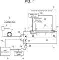
- an analysis system 1 mainly includes a sample vaporization chamber 2, a separation column 4, an oxidation decomposition device 6, a mass spectrometer 8, and a switching valve 10.
- the sample vaporization chamber 2 and the separation column 4 form a gas chromatograph.
- An injected sample is vaporized in the sample vaporization chamber 2, and the vaporized sample is introduced into the separation column 4 together with carrier gas.
- the gas chromatograph including the sample vaporization chamber 2 and the separation column 4 forms a sample supply device configured to supply the sample to the oxidation decomposition device 6.
- the switching valve 10 has first to sixth ports, and is a two-position valve switchable between two positions, i.e., a position (position in Fig. 1 ) in which the first port and the sixth port are in fluid communication with each other, the second port and the third port are in fluid communication with each other, and the fourth port and the fifth port are in fluid communication with each other and a position (position in Fig. 2 ) in which the first port and the second port are in fluid communication with each other, the third port and the fourth port are in fluid communication with each other, and the fifth port and the sixth port are in fluid communication with each other.
- a flow path 16 communicating with the inlet of the mass spectrometer 8 is in fluid connection with the first port of the switching valve 10, the downstream end of the separation column 4 is in fluid connection with the second port, an inlet flow path 12 communicating with the oxidation decomposition device 6 is in fluid connection with the third port, the fourth port is closed, a depressurization flow path 22 is in fluid connection with the fifth port, and an outlet flow path 14 communicating with the outlet of the oxidation decomposition device 6 is in fluid connection with the sixth port.
- the switching valve 10 is a switching mechanism configured to switch the gas chromatograph including the sample vaporization chamber 2 and the separation column 4 and the mass spectrometer 8 between a GC-MS mode (first state) in which the gas chromatograph and the mass spectrometer 8 are in fluid connection with each other without the oxidation decomposition device 6 interposed therebetween and a GC-Comb-MS mode (second state) in which the gas chromatograph and the mass spectrometer 8 are in fluid connection with each other with the oxidation decomposition device 6 interposed therebetween.
- Fig. 1 shows a flow path configuration in the GC-Comb-MS mode
- Fig. 2 shows a flow path configuration in the GC-MS mode.
- the oxidation decomposition device 6 includes a heating furnace 28, a reaction tube 30, an interface 32, an outlet adaptor 34, an oxidation gas supplier 36, and a makeup gas supplier 38.
- the reaction tube 30 is a circular tubular member configured such that at least the inner surface thereof is made of oxide containing 16 O, such as alumina, and having a high heat resistance.
- the reaction tube 30 is housed in the heating furnace 28 so as to penetrate the heating furnace 28, and is configured to oxidatively decompose the sample therein.
- the heating furnace 28 heats the reaction tube 30 housed inside to a set temperature.
- the interface 32 is provided on one end side (left side in the figure) of the reaction tube 30.
- the interface 32 has an inlet 33, and the downstream end of the inlet flow path 12 is in fluid connection with the inlet 33.
- the outlet adaptor 34 is provided on the other end side (right side in the figure) of the reaction tube 30. With the outlet adaptor 34, the upstream end of the outlet flow path 14 is in fluid connection with the other end of the reaction tube 30.
- the oxidation gas supplier 36 is a tank configured to supply, as oxidation gas, gas containing an oxygen isotope different from a specific oxygen compound contained in an oxygen-containing compound targeted for detection and/or quantitative determination.
- gas containing 17 O or 18 O as oxygen gas may be used as the oxidation gas.
- the oxidation gas may also contain inert gas such as helium gas or argon gas, and the ratio between the oxygen gas and the inert gas in the oxidation gas is, for example, 1 : 99.
- the oxidation gas supplied from the oxidation gas supplier 36 is introduced into the interface 32.
- the makeup gas supplier 38 is a tank different from the oxidation gas supplier 36, which is configured to supply inert gas not influencing oxidation decomposition of the sample in the reaction tube 30.
- Examples of makeup gas include helium gas.
- the makeup gas supplied from the makeup gas supplier 38 is introduced into the interface 32 and the outlet adaptor 34.
- the inlet flow path 12 is connected to the downstream of the separation column 4, and the sample having flowed out of the separation column 4 is introduced into the interface 32 of the oxidation decomposition device 6 through the inlet flow path 12.
- the sample introduced into the interface 32 is introduced into the reaction tube 30 together with the oxidation gas supplied from the oxidation gas supplier 36 and the makeup gas supplied from the makeup gas supplier 38, and after having been oxidatively decomposed in the reaction tube 30, is introduced into the mass spectrometer 8.
- a hollow cylindrical outer tube 40 is provided so as to surround the outer periphery of the reaction tube 30 of the oxidation decomposition device 6.
- the heating furnace 28 contacts the outer peripheral surface of the outer tube 40, and therefore, the outer tube 40 is heated by the heating furnace 28 and the reaction tube 30 passing inside the outer tube 40 is heated.
- the reaction tube 30 and the outer tube 40 do not contact each other, and there is a clearance 64 between the outer peripheral surface of the reaction tube 30 and the inner peripheral surface of the outer tube 40.
- a main portion housed in the heating furnace 28 may be made of a heat-resisting material such as alumina, and at least an end portion held on the interface 32 may be made of metal, for example.
- a space 42 where a pipe (hereinafter also referred to as a pipe 12) forming the inlet flow path 12 and the reaction tube 30 are in fluid connection with each other is provided.
- the outer peripheral surface of the outer tube 40 on one end side (left side in the figure) is provided with a thread.
- An opening is provided in the heating-furnace-28-side surface of the interface 32, and a thread to be screwed with the thread at the outer peripheral surface of the outer tube 40 on one end side is provided inside the opening.
- the outer tube 40 is held on the interface 32 in such a manner that the thread at the outer peripheral surface of the outer tube 40 on one end side is screwed with the thread inside the opening of the interface 32.
- a holder 48 and a packing 54 are provided so as to be sandwiched between the far-side inner surface of the opening and the end portion of the outer tube 40.
- the holder 48 is for fixing the position of one end of the reaction tube 30 in the interface 32.
- the packing 54 is for avoiding gas in the internal space 42 from leaking to the outside of the interface 32 through the outside of the outer tube 40.
- the surface of the interface 32 opposite to the heating furnace 28 is provided with a hole, which is the inlet 33, through which the pipe forming the inlet flow path 12 is inserted.
- the pipe 12 is air-tightly inserted into the internal space 42 of the interface 32 through the inlet 33, and extends toward one end of the reaction tube 30.
- the interface 32 is provided with a makeup gas introduction flow path 50 for introducing the makeup gas supplied from the makeup gas supplier 38 into the internal space 42 and an oxidation gas introduction flow path 52 for introducing the oxidation gas supplied from the oxidation gas supplier 36 into the internal space 42.
- the makeup gas introduced through the makeup gas introduction flow path 50 is introduced into a clearance between the inner surface of the interface 32 and the outer peripheral surface of the pipe 12, and the oxidation gas introduced through the oxidation gas introduction flow path 52 is introduced into between the downstream end of the pipe 12 and one end of the reaction tube 30.
- the makeup gas introduced through the makeup gas introduction flow path 50 avoids the sample introduced into the internal space 42 through the pipe 12 from flowing back to the inlet 33 side.
- the outlet adaptor 34 has a structure of air-tightly holding the outer peripheral surface of the outer tube 40 on the other end side (right side in the figure) through O-rings 60, 62 and air-tightly holding the outer peripheral surface of the reaction tube 30 on the other end side (right side in the figure) through an O-ring 58.
- a pipe (hereinafter also referred to as a pipe 14) forming the outlet flow path 14 is air-tightly inserted through the surface of the outlet adaptor 34 opposite to the heating furnace 28, and in the outlet adaptor 34, the other end of the reaction tube 30 and the pipe 14 are air-tightly in fluid connection with each other.
- the outlet adaptor 34 is provided with a makeup gas introduction flow path 56 for introducing the makeup gas supplied from the makeup gas supplier 38 into the outlet adaptor 34.
- the makeup gas introduced through the makeup gas introduction flow path 56 flows into the internal space 42 of the interface 32 through the clearance 64 between the outer peripheral surface of the reaction tube 30 and the inner peripheral surface of the outer tube 40. This avoids the sample introduced into the internal space 42 of the interface 32 through the pipe 12 from flowing to the outlet adaptor 34 side through the outside of the reaction tube 30.
- the sample introduced into the internal space 42 of the interface 32 through the pipe 12 flows in the reaction tube 30 together with the oxidation gas and the makeup gas, and after having been oxidatively decomposed in the reaction tube 30, is introduced into the mass spectrometer 8 through the pipe 14.
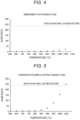
- Fig. 4 shows the data measured with supply of helium gas as the makeup gas
- Fig. 5 shows the data measured without supply of the makeup gas.
- the 44/46 ratio greatly increases as the temperature of the heating furnace 28 increases. This is because of the assumption that exchange between 16 O contained in alumina which is the material of the reaction tube 30 and 18 O of C 16 O 18 O generated by oxidation decomposition is accelerated as the temperature of the reaction tube 30 increases and C 16 O 18 O changes into C 16 O 2 accordingly. Due to such exchange between 16 O contained in the material of the reaction tube 30 and the oxygen isotope contained in the composition after oxidation decomposition, the composition ratio after oxidation decomposition changes, and the accuracy of detection or quantitative determination for the oxygen-containing compound contained in the sample is degraded.
- the data of Fig. 5 clearly shows that oxygen exchange between the material of the reaction tube 30 and the composition after oxidation decomposition cannot be reduced with the inert gas contained in the oxidation gas and the inert gas which is the carrier gas.
- the 44/46 ratio does not greatly change although slightly increasing at a heating furnace temperature of exceeding 900°C.
- the data shows that in a case where the sample is oxidatively decomposed while the inert gas is supplied, as the makeup gas, to the inlet portion of the reaction tube 30 separately from the oxidation gas and the carrier gas, an effect of decreasing an opportunity of the material of the reaction tube 30 and the composition after oxidation decomposition contacting each other, reducing exchange between 16 O contained in the material of the reaction tube 30 and the oxygen isotope contained in the composition after oxidation decomposition, and reducing a change in the composition ratio of the sample after oxidation decomposition is obtained.
- a suction pump 18 is connected to the mass spectrometer 8 through a flow path 20, and the inside of the mass spectrometer 8 is depressurized.
- the depressurization flow path 22 is in fluid connection with the suction pump 18.
- a stop valve 24 and a flow path resistance adjuster 26 are provided on the depressurization flow path 22.
- the depressurization flow path 22 is in fluid communication with the outlet flow path 14, and the inside of the reaction tube 30 and the inside of the outlet flow path 14 are depressurized by the suction pump 18.
- the analysis system 1 is in the GC-MS mode until a target component is eluted from the separation column 4, and is switched to the GC-Comb-MS mode at timing of eluting the target component from the separation column 4 to oxidatively decompose the target component. Then, the mass spectrometric data on the composition after oxidation decomposition is acquired.
- the target component is introduced into the mass spectrometer 8 before the base line is stabilized, leading to a probability that the accuracy of detection of the target component is degraded.
- the analysis system 1 is designed such that a difference between the internal pressure of the reaction tube 30 in the GC-MS mode and the internal pressure of the reaction tube 30 in the GC-Comb-MS mode falls within an acceptable range (e.g., within 10% of the internal pressure of the reaction tube 30 in the GC-Comb-MS mode, but preferably as small range as possible) set considering fluctuation in the internal pressure of the reaction tube 30 when the GC-MS mode is switched to the GC-Comb-MS mode.
- an acceptable range e.g., within 10% of the internal pressure of the reaction tube 30 in the GC-Comb-MS mode, but preferably as small range as possible
- the flow path resistance adjuster 26 is provided on the depressurization flow path 22, and therefore, the efficiency of depressurization in a system from the oxidation decomposition device 6 to the suction pump 18 in the GC-MS mode approaches the efficiency of depressurization in the system from the oxidation decomposition device 6 to the suction pump 18 in the GC-Comb-MS mode.
- the flow path resistance adjuster 26 may be a resistance tube with a fixed flow path resistance value, but may be, e.g., a needle valve or a proportional solenoid valve, the flow path resistance of which is variably adjustable.
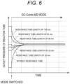
- Fig. 6 shows data indicating results of verification on the influence of the length of the resistance tube which is the flow path resistance adjuster 26 on fluctuation in the outlet pressure of the reaction tube 30 when the GC-MS mode is switched to the GC-Comb-MS mode.
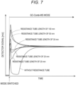
- Fig. 7 shows data indicating results of verification on the influence of the length of the resistance tube which is the flow path resistance adjuster 26 on fluctuation in the base line of the output signal of the mass spectrometer 8 when the GC-MS mode is switched to the GC-Comb-MS mode.
- the outlet pressure of the reaction tube 30 is extremely low in the GC-MS mode. Accordingly, when the GC-MS mode is switched to the GC-Comb-MS mode, the outlet pressure of the reaction tube 30 greatly fluctuates, the base line of the output signal (detector signal) of the mass spectrometer 8 also greatly fluctuates, and the time required until the base line is stabilized increases. As the flow path resistance of the depressurization flow path 22 increases by the resistance tube provided on the depressurization flow path 22, the internal pressure of the reaction tube 30 in the GC-MS mode increases.
- the flow path resistance of the depressurization flow path 22 incorporated into the system from the oxidation decomposition device 6 to the suction pump 18 in the GC-MS mode is moderately adjusted by the flow path resistance adjuster 26 so that fluctuation in the internal pressure of the reaction tube 30 when the GC-MS mode is switched to the GC-Comb-MS mode can be decreased.
- One embodiment of the analysis system according to the present invention is an analysis system for detecting and/or quantitatively determining a compound containing a specific oxygen component in a sample, the analysis system including an oxidation decomposition device having an inlet and an outlet and configured to oxidatively decompose the sample introduced through the inlet to discharge the sample through the outlet, and a detector configured to detect an oxidation reactant oxidatively decomposed by the oxidation decomposition device, and the oxidation decomposition device including
- the oxidation gas supplied from the oxidation gas supplier and the makeup gas supplied from the makeup gas supplier are supplied to the interface through different flow paths.
- the interface includes an internal space where the sample introduced through the inlet, the oxidation gas, and the makeup gas are joined together in the reaction tube, an oxidation gas introduction flow path through which the oxidation gas supplied from the oxidation gas supplier is introduced into the internal space, and a makeup gas introduction flow path through which the makeup gas supplied from the makeup gas supplier is introduced into the internal space, and has a structure of introducing the sample, the oxidation gas, and the makeup gas joined together in the internal space into the reaction tube from the one end thereof.
- At least the inner surface of the reaction tube is made of a heat-resisting material containing oxide.
- the aspect [2] may be combined with the above-described aspect [1] .
- the heat-resisting material may be alumina.
- the analysis system further includes
- the suction pump in the first state, may be in fluid connection with the mass spectrometer simultaneously when the suction pump is in fluid connection with the downstream of the oxidation decomposition device, and in the second state, the suction pump may be in fluid connection with the mass spectrometer.
- the resistance of a flow path incorporated into between the oxidation decomposition device and the suction pump in the first state may be set such that the efficiency of depressurization in a system from the oxidation decomposition device to the suction pump in the first state and the efficiency of depressurization in the system from the oxidation decomposition device to the suction pump in the second state are substantially identical to each other.
- the acceptable range may be within 10% of the internal pressure of the reaction tube in the second state.
- the sample supply device may be a gas chromatograph.
Landscapes
- Health & Medical Sciences (AREA)
- Life Sciences & Earth Sciences (AREA)
- Chemical & Material Sciences (AREA)
- General Health & Medical Sciences (AREA)
- Analytical Chemistry (AREA)
- Biochemistry (AREA)
- Physics & Mathematics (AREA)
- General Physics & Mathematics (AREA)
- Immunology (AREA)
- Pathology (AREA)
- Molecular Biology (AREA)
- Engineering & Computer Science (AREA)
- Combustion & Propulsion (AREA)
- Other Investigation Or Analysis Of Materials By Electrical Means (AREA)
- Investigating Or Analyzing Non-Biological Materials By The Use Of Chemical Means (AREA)
Abstract
Description
- The present invention relates to an analysis system including an oxidation decomposition device configured to oxidatively decompose a sample.
- A method for detecting or quantitatively determining an oxygen component in a sample containing an oxygen component (e.g., 16O) has been proposed (see
JP-A-2019-508711 - In order to perform the above-described method, it is necessary to fully oxidatively decompose the sample by supplying the sample and the oxidation gas into a reaction tube heated to a high temperature (e.g., about 600 to 1000°C), and for this reason, a material having a high heat resistance needs to be used as the material of the reaction tube. A ceramics material such as alumina is conceivable as the material having the high heat resistance. However, experimental results show that if oxidation decomposition is performed using a reaction tube made of alumina, a composition ratio after oxidation decomposition changes as the temperature of heating of the reaction tube increases. For example, it has been found that in a case where the ratio of C16O2 (m/z = 44) to C18O16O (m/z = 46) is detected while the temperature of heating of the reaction tube is changed, the percentage of C16O2 increases as the temperature of heating of the reaction tube increases (see
Fig. 5 ). This is because of the assumption that C18O16O generated by oxidation decomposition using the oxidation gas containing 18O changes into C16O2 for some reason. If analysis described in the background art is performed under such a situation, it cannot be accurately determined whether the oxygen component in the composition detected by, e.g., the mass spectroscope is derived from the sample or the oxidation gas. - For these reasons, the present invention is intended to provide an analysis system having improved detection or quantitative determination accuracy in a method for detecting or quantitatively determining an oxygen component in a sample by oxidatively decomposing the sample using oxidation gas containing an oxygen isotope different from natural isotopes in composition and distribution and detecting a composition obtained by oxidation decomposition.
- As a result of intensive study on a cause for the above-described change from C18O16O to C16O2, it has been found that substitution between 16O contained in alumina (Al2O3) which is the material of the reaction tube and 18O of C18O16O is caused while C18O16O passes through the reaction tube. Based on such a finding, the following analysis system has been invented.
- That is, the analysis system according to the present invention is an analysis system for detecting and/or quantitatively determining a compound containing a specific oxygen component in a sample, the analysis system including
- an oxidation decomposition device having an inlet and an outlet and configured to oxidatively decompose the sample introduced through the inlet to discharge the sample through the outlet, and a detector configured to detect an oxidation reactant oxidatively decomposed by the oxidation decomposition device, and
- the oxidation decomposition device including
- a reaction tube having one end and the other end such that the one end is arranged on the inlet side and the other end is arranged on the outlet side and configured to oxidatively decompose the sample inside,
- a heating furnace housing the reaction tube inside and configured to heat the reaction tube,
- an oxidation gas supplier configured to supply oxidation gas used for oxidizing the sample and containing an oxygen component of an isotope different from the specific oxygen component,
- a makeup gas supplier configured to supply makeup gas which is inert gas not influencing oxidation decomposition of the sample, and
- an interface having a structure of introducing the oxidation gas supplied from the oxidation gas supplier and the makeup gas supplied from the makeup gas supplier into the reaction tube together with the sample introduced through the inlet.
- According to the analysis system of the present invention, the interface of the oxidation decomposition device has the structure of introducing the oxidation gas and the makeup gas into the reaction tube together with the sample introduced through the inlet. Therefore, an opportunity of the composition after oxidation decomposition and the inner surface of the reaction tube contacting each other in the reaction tube is limited and substitution between 16O contained in the material of the reaction tube and the oxygen isotope contained in the composition after oxidation decomposition is reduced. Thus, the detection or quantitative determination accuracy is improved in the method for detecting or quantitatively determining the oxygen component in the sample by oxidatively decomposing the sample using the oxidation gas containing the oxygen isotope different from natural isotopes in composition and distribution and detecting the composition obtained by oxidation decomposition.
-
-
Fig. 1 is a flow path configuration diagram in a GC-Comb-MS mode in one embodiment of an analysis system; -
Fig. 2 is a flow path configuration diagram in a GC-MS mode in the embodiment; -
Fig. 3 is a sectional view showing one example of the structure of an oxidation decomposition device of the embodiment; -
Fig. 4 is a graph showing results of verification on a relationship between the 44/46 ratio of 18-methanol and a heating furnace temperature in the GC-Comb-MS mode of the embodiment; -
Fig. 5 is a graph showing results of verification on a relationship between the 44/46 ratio of 18-methanol and the heating furnace temperature in the GC-Comb-MS mode in a case where no makeup gas is used in the oxidation decomposition device; -
Fig. 6 is a graph showing a relationship between the length of a resistance tube and fluctuation in the outlet pressure of a reaction tube when the GC-MS mode is switched to the GC-Comb-MS mode in the embodiment; and -
Fig. 7 is a graph showing a relationship between the length of the resistance tube and fluctuation in the base line of a detector signal of a mass spectrometer when the GC-MS mode is switched to the GC-Comb-MS mode in the embodiment. - Hereinafter, one embodiment of an analysis system according to the present invention will be described with reference to the drawings.
- As shown in
Figs. 1 and2 , ananalysis system 1 mainly includes asample vaporization chamber 2, aseparation column 4, anoxidation decomposition device 6, amass spectrometer 8, and aswitching valve 10. Thesample vaporization chamber 2 and theseparation column 4 form a gas chromatograph. An injected sample is vaporized in thesample vaporization chamber 2, and the vaporized sample is introduced into theseparation column 4 together with carrier gas. In theseparation column 4, components in the sample are separated from each other. The gas chromatograph including thesample vaporization chamber 2 and theseparation column 4 forms a sample supply device configured to supply the sample to theoxidation decomposition device 6. - The
switching valve 10 has first to sixth ports, and is a two-position valve switchable between two positions, i.e., a position (position inFig. 1 ) in which the first port and the sixth port are in fluid communication with each other, the second port and the third port are in fluid communication with each other, and the fourth port and the fifth port are in fluid communication with each other and a position (position inFig. 2 ) in which the first port and the second port are in fluid communication with each other, the third port and the fourth port are in fluid communication with each other, and the fifth port and the sixth port are in fluid communication with each other. - A
flow path 16 communicating with the inlet of themass spectrometer 8 is in fluid connection with the first port of theswitching valve 10, the downstream end of theseparation column 4 is in fluid connection with the second port, aninlet flow path 12 communicating with theoxidation decomposition device 6 is in fluid connection with the third port, the fourth port is closed, adepressurization flow path 22 is in fluid connection with the fifth port, and anoutlet flow path 14 communicating with the outlet of theoxidation decomposition device 6 is in fluid connection with the sixth port. - The
switching valve 10 is a switching mechanism configured to switch the gas chromatograph including thesample vaporization chamber 2 and theseparation column 4 and themass spectrometer 8 between a GC-MS mode (first state) in which the gas chromatograph and themass spectrometer 8 are in fluid connection with each other without theoxidation decomposition device 6 interposed therebetween and a GC-Comb-MS mode (second state) in which the gas chromatograph and themass spectrometer 8 are in fluid connection with each other with theoxidation decomposition device 6 interposed therebetween.Fig. 1 shows a flow path configuration in the GC-Comb-MS mode, andFig. 2 shows a flow path configuration in the GC-MS mode. - The
oxidation decomposition device 6 includes aheating furnace 28, areaction tube 30, aninterface 32, anoutlet adaptor 34, anoxidation gas supplier 36, and amakeup gas supplier 38. - The
reaction tube 30 is a circular tubular member configured such that at least the inner surface thereof is made of oxide containing 16O, such as alumina, and having a high heat resistance. Thereaction tube 30 is housed in theheating furnace 28 so as to penetrate theheating furnace 28, and is configured to oxidatively decompose the sample therein. Theheating furnace 28 heats thereaction tube 30 housed inside to a set temperature. - The
interface 32 is provided on one end side (left side in the figure) of thereaction tube 30. Theinterface 32 has aninlet 33, and the downstream end of theinlet flow path 12 is in fluid connection with theinlet 33. - The
outlet adaptor 34 is provided on the other end side (right side in the figure) of thereaction tube 30. With theoutlet adaptor 34, the upstream end of theoutlet flow path 14 is in fluid connection with the other end of thereaction tube 30. - The
oxidation gas supplier 36 is a tank configured to supply, as oxidation gas, gas containing an oxygen isotope different from a specific oxygen compound contained in an oxygen-containing compound targeted for detection and/or quantitative determination. For example, in the case of targeting a compound containing 16O for detection and/or quantitative determination, gas containing 17O or 18O as oxygen gas may be used as the oxidation gas. The oxidation gas may also contain inert gas such as helium gas or argon gas, and the ratio between the oxygen gas and the inert gas in the oxidation gas is, for example, 1 : 99. The oxidation gas supplied from theoxidation gas supplier 36 is introduced into theinterface 32. - The
makeup gas supplier 38 is a tank different from theoxidation gas supplier 36, which is configured to supply inert gas not influencing oxidation decomposition of the sample in thereaction tube 30. Examples of makeup gas include helium gas. The makeup gas supplied from themakeup gas supplier 38 is introduced into theinterface 32 and theoutlet adaptor 34. - In the GC-Comb-MS mode shown in
Fig. 1 , theinlet flow path 12 is connected to the downstream of theseparation column 4, and the sample having flowed out of theseparation column 4 is introduced into theinterface 32 of theoxidation decomposition device 6 through theinlet flow path 12. The sample introduced into theinterface 32 is introduced into thereaction tube 30 together with the oxidation gas supplied from theoxidation gas supplier 36 and the makeup gas supplied from themakeup gas supplier 38, and after having been oxidatively decomposed in thereaction tube 30, is introduced into themass spectrometer 8. - Here, one example of a specific structure of the
oxidation decomposition device 6 will be described with reference toFig. 3 . - A hollow cylindrical
outer tube 40 is provided so as to surround the outer periphery of thereaction tube 30 of theoxidation decomposition device 6. Theheating furnace 28 contacts the outer peripheral surface of theouter tube 40, and therefore, theouter tube 40 is heated by theheating furnace 28 and thereaction tube 30 passing inside theouter tube 40 is heated. Thereaction tube 30 and theouter tube 40 do not contact each other, and there is aclearance 64 between the outer peripheral surface of thereaction tube 30 and the inner peripheral surface of theouter tube 40. Of theouter tube 40, a main portion housed in theheating furnace 28 may be made of a heat-resisting material such as alumina, and at least an end portion held on theinterface 32 may be made of metal, for example. - In the
interface 32, aspace 42 where a pipe (hereinafter also referred to as a pipe 12) forming theinlet flow path 12 and thereaction tube 30 are in fluid connection with each other is provided. Although not shown in the figure, the outer peripheral surface of theouter tube 40 on one end side (left side in the figure) is provided with a thread. An opening is provided in the heating-furnace-28-side surface of theinterface 32, and a thread to be screwed with the thread at the outer peripheral surface of theouter tube 40 on one end side is provided inside the opening. Theouter tube 40 is held on theinterface 32 in such a manner that the thread at the outer peripheral surface of theouter tube 40 on one end side is screwed with the thread inside the opening of theinterface 32. In the opening of theinterface 32, aholder 48 and a packing 54 are provided so as to be sandwiched between the far-side inner surface of the opening and the end portion of theouter tube 40. Theholder 48 is for fixing the position of one end of thereaction tube 30 in theinterface 32. The packing 54 is for avoiding gas in theinternal space 42 from leaking to the outside of theinterface 32 through the outside of theouter tube 40. - The surface of the
interface 32 opposite to theheating furnace 28 is provided with a hole, which is theinlet 33, through which the pipe forming theinlet flow path 12 is inserted. Thepipe 12 is air-tightly inserted into theinternal space 42 of theinterface 32 through theinlet 33, and extends toward one end of thereaction tube 30. Theinterface 32 is provided with a makeup gasintroduction flow path 50 for introducing the makeup gas supplied from themakeup gas supplier 38 into theinternal space 42 and an oxidation gasintroduction flow path 52 for introducing the oxidation gas supplied from theoxidation gas supplier 36 into theinternal space 42. The makeup gas introduced through the makeup gasintroduction flow path 50 is introduced into a clearance between the inner surface of theinterface 32 and the outer peripheral surface of thepipe 12, and the oxidation gas introduced through the oxidation gasintroduction flow path 52 is introduced into between the downstream end of thepipe 12 and one end of thereaction tube 30. The makeup gas introduced through the makeup gasintroduction flow path 50 avoids the sample introduced into theinternal space 42 through thepipe 12 from flowing back to theinlet 33 side. - The
outlet adaptor 34 has a structure of air-tightly holding the outer peripheral surface of theouter tube 40 on the other end side (right side in the figure) through O-rings reaction tube 30 on the other end side (right side in the figure) through an O-ring 58. A pipe (hereinafter also referred to as a pipe 14) forming theoutlet flow path 14 is air-tightly inserted through the surface of theoutlet adaptor 34 opposite to theheating furnace 28, and in theoutlet adaptor 34, the other end of thereaction tube 30 and thepipe 14 are air-tightly in fluid connection with each other. Theoutlet adaptor 34 is provided with a makeup gasintroduction flow path 56 for introducing the makeup gas supplied from themakeup gas supplier 38 into theoutlet adaptor 34. The makeup gas introduced through the makeup gasintroduction flow path 56 flows into theinternal space 42 of theinterface 32 through theclearance 64 between the outer peripheral surface of thereaction tube 30 and the inner peripheral surface of theouter tube 40. This avoids the sample introduced into theinternal space 42 of theinterface 32 through thepipe 12 from flowing to theoutlet adaptor 34 side through the outside of thereaction tube 30. - The sample introduced into the
internal space 42 of theinterface 32 through thepipe 12 flows in thereaction tube 30 together with the oxidation gas and the makeup gas, and after having been oxidatively decomposed in thereaction tube 30, is introduced into themass spectrometer 8 through thepipe 14. -
Figs. 4 and 5 show data in the GC-Comb-MS mode on the abundance ratio (44/46 ratio) between C16O2 (mass number = 44) and C16O18O (mass number = 46) in the sample after oxidation decomposition based on mass spectrometric data at each temperature, the mass spectrometric data being acquired for different temperatures of theheating furnace 28 in a case where a gas mixture of 16O and inert gas (16O gas : inert gas = 1 : 99) is supplied as the oxidation gas and 18-ethanol (CH3 18OH) which is an oxygen-containing compound containing 18O is injected as the sample.Fig. 4 shows the data measured with supply of helium gas as the makeup gas, andFig. 5 shows the data measured without supply of the makeup gas. - As shown in the data of
Fig. 5 , in the case of not using the makeup gas, the 44/46 ratio greatly increases as the temperature of theheating furnace 28 increases. This is because of the assumption that exchange between 16O contained in alumina which is the material of thereaction tube 30 and 18O of C16O18O generated by oxidation decomposition is accelerated as the temperature of thereaction tube 30 increases and C16O18O changes into C16O2 accordingly. Due to such exchange between 16O contained in the material of thereaction tube 30 and the oxygen isotope contained in the composition after oxidation decomposition, the composition ratio after oxidation decomposition changes, and the accuracy of detection or quantitative determination for the oxygen-containing compound contained in the sample is degraded. Although not only the oxidation gas contains the inert gas, but also the inert gas is supplied as the carrier gas, the data ofFig. 5 clearly shows that oxygen exchange between the material of thereaction tube 30 and the composition after oxidation decomposition cannot be reduced with the inert gas contained in the oxidation gas and the inert gas which is the carrier gas. - On the other hand, as shown in the data of
Fig. 4 , in a case where the makeup gas is introduced into thereaction tube 30 together with the sample, the 44/46 ratio does not greatly change although slightly increasing at a heating furnace temperature of exceeding 900°C. The data shows that in a case where the sample is oxidatively decomposed while the inert gas is supplied, as the makeup gas, to the inlet portion of thereaction tube 30 separately from the oxidation gas and the carrier gas, an effect of decreasing an opportunity of the material of thereaction tube 30 and the composition after oxidation decomposition contacting each other, reducing exchange between 16O contained in the material of thereaction tube 30 and the oxygen isotope contained in the composition after oxidation decomposition, and reducing a change in the composition ratio of the sample after oxidation decomposition is obtained. - Referring back to
Figs. 1 and2 , theanalysis system 1 will be continuously described. - A
suction pump 18 is connected to themass spectrometer 8 through aflow path 20, and the inside of themass spectrometer 8 is depressurized. Thedepressurization flow path 22 is in fluid connection with thesuction pump 18. Astop valve 24 and a flowpath resistance adjuster 26 are provided on thedepressurization flow path 22. As shown inFig. 2 , in the GC-MS mode, thedepressurization flow path 22 is in fluid communication with theoutlet flow path 14, and the inside of thereaction tube 30 and the inside of theoutlet flow path 14 are depressurized by thesuction pump 18. - For example, the
analysis system 1 is in the GC-MS mode until a target component is eluted from theseparation column 4, and is switched to the GC-Comb-MS mode at timing of eluting the target component from theseparation column 4 to oxidatively decompose the target component. Then, the mass spectrometric data on the composition after oxidation decomposition is acquired. - However, it is assumed as follows: if the internal pressure of the
reaction tube 30 in the GC-MS mode is greatly different from the internal pressure of thereaction tube 30 in the GC-Comb-MS mode, the internal pressure of thereaction tube 30 greatly fluctuates when the GC-MS mode is switched to the GC-Comb-MS mode, and for this reason, time until the internal pressure of thereaction tube 30 is stabilized is long; meanwhile, if the target component is introduced into the reaction tube, the efficiency of oxidation decomposition of the target component is degraded. Moreover, it has been found that if the internal pressure of thereaction tube 30 greatly fluctuates, the base line of an output signal of themass spectrometer 8 also greatly fluctuates and time required until the base line is stabilized is also long. If the time required until the base line of the output signal of themass spectrometer 8 is stabilized is long, the target component is introduced into themass spectrometer 8 before the base line is stabilized, leading to a probability that the accuracy of detection of the target component is degraded. - For these reasons, the
analysis system 1 is designed such that a difference between the internal pressure of thereaction tube 30 in the GC-MS mode and the internal pressure of thereaction tube 30 in the GC-Comb-MS mode falls within an acceptable range (e.g., within 10% of the internal pressure of thereaction tube 30 in the GC-Comb-MS mode, but preferably as small range as possible) set considering fluctuation in the internal pressure of thereaction tube 30 when the GC-MS mode is switched to the GC-Comb-MS mode. In theanalysis system 1, the flowpath resistance adjuster 26 is provided on thedepressurization flow path 22, and therefore, the efficiency of depressurization in a system from theoxidation decomposition device 6 to thesuction pump 18 in the GC-MS mode approaches the efficiency of depressurization in the system from theoxidation decomposition device 6 to thesuction pump 18 in the GC-Comb-MS mode. Thus, the difference between the internal pressure of thereaction tube 30 in the GC-MS mode and the internal pressure of thereaction tube 30 in the GC-Comb-MS mode falls within the acceptable range. The flowpath resistance adjuster 26 may be a resistance tube with a fixed flow path resistance value, but may be, e.g., a needle valve or a proportional solenoid valve, the flow path resistance of which is variably adjustable. -
Fig. 6 shows data indicating results of verification on the influence of the length of the resistance tube which is the flowpath resistance adjuster 26 on fluctuation in the outlet pressure of thereaction tube 30 when the GC-MS mode is switched to the GC-Comb-MS mode.Fig. 7 shows data indicating results of verification on the influence of the length of the resistance tube which is the flowpath resistance adjuster 26 on fluctuation in the base line of the output signal of themass spectrometer 8 when the GC-MS mode is switched to the GC-Comb-MS mode. - According to the data of
Figs. 6 and7 , in the case of not providing the resistance tube on thedepressurization flow path 22, the outlet pressure of thereaction tube 30 is extremely low in the GC-MS mode. Accordingly, when the GC-MS mode is switched to the GC-Comb-MS mode, the outlet pressure of thereaction tube 30 greatly fluctuates, the base line of the output signal (detector signal) of themass spectrometer 8 also greatly fluctuates, and the time required until the base line is stabilized increases. As the flow path resistance of thedepressurization flow path 22 increases by the resistance tube provided on thedepressurization flow path 22, the internal pressure of thereaction tube 30 in the GC-MS mode increases. In the case of providing the resistance tube with a length of 30 mm, fluctuation in the outlet pressure of thereaction tube 30 is the smallest, and fluctuation in the base line of the detector signal is also the smallest. On the other hand, in a case where the length of the resistance tube is 50 mm or more, the internal pressure of thereaction tube 30 in the GC-MS mode is higher than that in the GC-Comb-MS mode, and therefore, the pressure greatly fluctuates when the GC-MS mode is switched to the GC-Comb-MS mode. - The above-described verification results show as follows: the flow path resistance of the
depressurization flow path 22 incorporated into the system from theoxidation decomposition device 6 to thesuction pump 18 in the GC-MS mode is moderately adjusted by the flowpath resistance adjuster 26 so that fluctuation in the internal pressure of thereaction tube 30 when the GC-MS mode is switched to the GC-Comb-MS mode can be decreased. - Note that the embodiment described above is merely one exemplary embodiment of the analysis system according to the present invention. One embodiment of the analysis system according to the present invention is as follows.
- One embodiment of the analysis system according to the present invention is an analysis system for detecting and/or quantitatively determining a compound containing a specific oxygen component in a sample, the analysis system including an oxidation decomposition device having an inlet and an outlet and configured to oxidatively decompose the sample introduced through the inlet to discharge the sample through the outlet, and a detector configured to detect an oxidation reactant oxidatively decomposed by the oxidation decomposition device, and
the oxidation decomposition device including - a reaction tube having one end and the other end such that the one end is arranged on the inlet side and the other end is arranged on the outlet side and configured to oxidatively decompose the sample inside,
- a heating furnace housing the reaction tube inside and configured to heat the reaction tube,
- an oxidation gas supplier configured to supply oxidation gas used for oxidizing the sample and containing an oxygen component of an isotope different from the specific oxygen component,
- a makeup gas supplier configured to supply makeup gas which is inert gas not influencing oxidation decomposition of the sample, and
- an interface having a structure of introducing the oxidation gas supplied from the oxidation gas supplier and the makeup gas supplied from the makeup gas supplier into the reaction tube together with the sample introduced through the inlet.
- In an aspect [1] of the above-described one embodiment, the oxidation gas supplied from the oxidation gas supplier and the makeup gas supplied from the makeup gas supplier are supplied to the interface through different flow paths.
- Preferably, in the above-described aspect [1], the interface includes an internal space where the sample introduced through the inlet, the oxidation gas, and the makeup gas are joined together in the reaction tube, an oxidation gas introduction flow path through which the oxidation gas supplied from the oxidation gas supplier is introduced into the internal space, and a makeup gas introduction flow path through which the makeup gas supplied from the makeup gas supplier is introduced into the internal space, and has a structure of introducing the sample, the oxidation gas, and the makeup gas joined together in the internal space into the reaction tube from the one end thereof.
- In an aspect [2] of the above-described one embodiment, at least the inner surface of the reaction tube is made of a heat-resisting material containing oxide. The aspect [2] may be combined with the above-described aspect [1] .
- In the above-described aspect [2], the heat-resisting material may be alumina.
- In an aspect [3] of the above-described one embodiment, the analysis system further includes
- a sample supply device (2, 4) having a configuration of supplying the sample downstream by carrier gas,
- a mass spectrometer which is the detector,
- a switching mechanism configured to switch flow path connection, and
- a suction pump configured to depressurize the inside of the reaction tube of the oxidation decomposition device,
- by switching by the switching mechanism, any of a first state in which the mass spectrometer is in fluid connection with the downstream of the sample supply device without the oxidation decomposition device interposed between the sample supply device and the mass spectrometer and a second state in which the inlet of the oxidation decomposition device is in fluid connection with the downstream of the sample supply device and the mass spectrometer is in fluid connection with the downstream of the outlet of the oxidation decomposition device being brought, and
- the suction pump being in fluid connection with the downstream of the oxidation decomposition device in the first state, and a difference between the internal pressure of the reaction tube in the first state and the internal pressure of the reaction tube in the second state falling within an acceptable range set considering the degree of fluctuation in the internal pressure of the reaction tube when the switching mechanism switches the first state to the second state. The aspect [3] may be combined with the above-described aspect [1] and/or the above-described aspect [2].
- In the above-described aspect [3], in the first state, the suction pump may be in fluid connection with the mass spectrometer simultaneously when the suction pump is in fluid connection with the downstream of the oxidation decomposition device, and in the second state, the suction pump may be in fluid connection with the mass spectrometer. In this case, the resistance of a flow path incorporated into between the oxidation decomposition device and the suction pump in the first state may be set such that the efficiency of depressurization in a system from the oxidation decomposition device to the suction pump in the first state and the efficiency of depressurization in the system from the oxidation decomposition device to the suction pump in the second state are substantially identical to each other.
- In the above-described aspect [3], the acceptable range may be within 10% of the internal pressure of the reaction tube in the second state.
- In the above-described aspect [3], the sample supply device may be a gas chromatograph.
-
- 1
- Analysis System
- 2
- Sample Vaporization Chamber
- 4
- Separation Column
- 6
- Oxidation Decomposition Device
- 10
- Switching Valve
- 12, 14, 16, 20, 22
- Flow Path
- 18
- Suction Pump
- 24
- Stop Valve
- 26
- Flow Path Resistance Adjuster
- 28
- Heating Furnace
- 30
- Reaction Tube
- 32
- Interface
- 33
- Inlet
- 34
- Outlet Adaptor
- 35
- Outlet
- 36
- Oxidation Gas Supplier
- 38
- Makeup Gas Supplier
- 40
- Outer Tube
- 42
- Internal Space
- 48
- Holder
- 50, 56
- Makeup Gas Introduction Flow Path
- 52
- Oxidation Gas Introduction Flow Path
- 54
- Packing
- 58, 60, 62
- O-Ring
Claims (9)
- An analysis system for detecting and/or quantitatively determining a compound containing a specific oxygen component in a sample, comprising:an oxidation decomposition device having an inlet and an outlet and configured to oxidatively decompose the sample introduced through the inlet to discharge the sample through the outlet; anda detector configured to detect an oxidation reactant oxidatively decomposed by the oxidation decomposition device,wherein the oxidation decomposition device includesa reaction tube having one end and another end such that the one end is arranged on an inlet side and the another end is arranged on an outlet side and configured to oxidatively decompose the sample inside,a heating furnace housing the reaction tube inside and configured to heat the reaction tube,an oxidation gas supplier configured to supply oxidation gas used for oxidizing the sample and containing an oxygen component of an isotope different from the specific oxygen component,a makeup gas supplier configured to supply makeup gas which is inert gas not influencing oxidation decomposition of the sample, andan interface having a structure of introducing the oxidation gas supplied from the oxidation gas supplier and the makeup gas supplied from the makeup gas supplier into the reaction tube together with the sample introduced through the inlet.
- The analysis system according to claim 1, wherein
the oxidation gas supplied from the oxidation gas supplier and the makeup gas supplied from the makeup gas supplier are supplied to the interface through different flow paths. - The analysis system according to claim 2, wherein
the interface includes an internal space where the sample introduced through the inlet, the oxidation gas, and the makeup gas are joined together in the reaction tube, an oxidation gas introduction flow path through which the oxidation gas supplied from the oxidation gas supplier is introduced into the internal space, and a makeup gas introduction flow path through which the makeup gas supplied from the makeup gas supplier is introduced into the internal space, and has a structure of introducing the sample, the oxidation gas, and the makeup gas joined together in the internal space into the reaction tube from the one end thereof. - The analysis system according to claim 1, wherein
at least an inner surface of the reaction tube is made of a heat-resisting material containing oxide. - The analysis system according to claim 4, wherein
the heat-resisting material is alumina. - The analysis system according to claim 1, further comprising:a sample supply device having a configuration of supplying the sample downstream by carrier gas;a mass spectrometer which is the detector;a switching mechanism configured to switch flow path connection; anda suction pump configured to depressurize an inside of the reaction tube of the oxidation decomposition device,wherein by switching by the switching mechanism, any of a first state in which the mass spectrometer is in fluid connection with downstream of the sample supply device without the oxidation decomposition device interposed between the sample supply device and the mass spectrometer and a second state in which the inlet of the oxidation decomposition device is in fluid connection with the downstream of the sample supply device and the mass spectrometer is in fluid connection with downstream of the outlet of the oxidation decomposition device is brought, andthe suction pump is in fluid connection with downstream of the oxidation decomposition device in the first state, and a difference between an internal pressure of the reaction tube in the first state and an internal pressure of the reaction tube in the second state falls within an acceptable range set considering a degree of fluctuation in the internal pressure of the reaction tube when the switching mechanism switches the first state to the second state.
- The analysis system according to claim 6, whereinin the first state, the suction pump is in fluid connection with the mass spectrometer simultaneously when the suction pump is in fluid connection with the downstream of the oxidation decomposition device, and in the second state, the suction pump is in fluid connection with the mass spectrometer, anda resistance of a flow path incorporated into between the oxidation decomposition device and the suction pump in the first state is set such that an efficiency of depressurization in a system from the oxidation decomposition device to the suction pump in the first state and an efficiency of depressurization in the system from the oxidation decomposition device to the suction pump in the second state are substantially identical to each other.
- The analysis system according to claim 6, wherein
the acceptable range is within 10% of the internal pressure of the reaction tube in the second state. - The analysis system according to claim 6, wherein
the sample supply device is a gas chromatograph.
Applications Claiming Priority (1)
| Application Number | Priority Date | Filing Date | Title |
|---|---|---|---|
| JP2023095978A JP2024177698A (en) | 2023-06-12 | 2023-06-12 | Analysis System |
Publications (2)
| Publication Number | Publication Date |
|---|---|
| EP4478044A1 true EP4478044A1 (en) | 2024-12-18 |
| EP4478044B1 EP4478044B1 (en) | 2026-02-04 |
Family
ID=91186711
Family Applications (1)
| Application Number | Title | Priority Date | Filing Date |
|---|---|---|---|
| EP24176845.6A Active EP4478044B1 (en) | 2023-06-12 | 2024-05-20 | Analysis system |
Country Status (5)
| Country | Link |
|---|---|
| US (1) | US20240410865A1 (en) |
| EP (1) | EP4478044B1 (en) |
| JP (1) | JP2024177698A (en) |
| CN (1) | CN119125334A (en) |
| ES (1) | ES3064429T3 (en) |
Citations (4)
| Publication number | Priority date | Publication date | Assignee | Title |
|---|---|---|---|---|
| US4409336A (en) * | 1981-02-17 | 1983-10-11 | Standard Oil Company (Indiana) | Method of analysis for determining very low sulfur levels in volatilizable samples |
| US5012052A (en) * | 1988-03-22 | 1991-04-30 | Indiana University Foundation | Isotope-ratio-monitoring gas chromatography-mass spectrometry apparatus and method |
| EP2236208A1 (en) * | 2009-04-03 | 2010-10-06 | Università degli Studi di Parma | Reactor device for chemical and isotopic analyses |
| JP2019508711A (en) | 2015-12-29 | 2019-03-28 | トタル ラフィナージュ シミ | Method for detecting and quantifying oxygen in oxidizable compounds |
-
2023
- 2023-06-12 JP JP2023095978A patent/JP2024177698A/en active Pending
-
2024
- 2024-05-20 EP EP24176845.6A patent/EP4478044B1/en active Active
- 2024-05-20 ES ES24176845T patent/ES3064429T3/en active Active
- 2024-05-23 CN CN202410643317.0A patent/CN119125334A/en active Pending
- 2024-06-07 US US18/737,075 patent/US20240410865A1/en active Pending
Patent Citations (4)
| Publication number | Priority date | Publication date | Assignee | Title |
|---|---|---|---|---|
| US4409336A (en) * | 1981-02-17 | 1983-10-11 | Standard Oil Company (Indiana) | Method of analysis for determining very low sulfur levels in volatilizable samples |
| US5012052A (en) * | 1988-03-22 | 1991-04-30 | Indiana University Foundation | Isotope-ratio-monitoring gas chromatography-mass spectrometry apparatus and method |
| EP2236208A1 (en) * | 2009-04-03 | 2010-10-06 | Università degli Studi di Parma | Reactor device for chemical and isotopic analyses |
| JP2019508711A (en) | 2015-12-29 | 2019-03-28 | トタル ラフィナージュ シミ | Method for detecting and quantifying oxygen in oxidizable compounds |
Also Published As
| Publication number | Publication date |
|---|---|
| JP2024177698A (en) | 2024-12-24 |
| EP4478044B1 (en) | 2026-02-04 |
| US20240410865A1 (en) | 2024-12-12 |
| CN119125334A (en) | 2024-12-13 |
| ES3064429T3 (en) | 2026-04-24 |
Similar Documents
| Publication | Publication Date | Title |
|---|---|---|
| US8448493B2 (en) | Gas chromatograph-combustion system and method for mass spectrometry | |
| CN102998362B (en) | The Field adjustment of mass spectrometer system | |
| CN109755097B (en) | A quadrupole mass spectrometer and method of using the same | |
| JPH02503958A (en) | Isotope abundance ratio monitoring gas chromatography mass spectrometry device and method | |
| JP2008508511A (en) | Ion mobility spectrometer with corona discharge ionization element | |
| US5416322A (en) | Interface for linking an atmospheric pressure thermogravimetric analyzer to a low pressure mass spectrometer | |
| KR20010013554A (en) | System for analyzing trace amounts of impurities in gases | |
| US9719971B2 (en) | Microfluidic flame ionization detector | |
| EP3776628B1 (en) | Imr-ms device | |
| EP4478044B1 (en) | Analysis system | |
| US8272249B1 (en) | Axial-geometry micro-discharge detector | |
| JP5251727B2 (en) | Multi-dimensional gas chromatograph | |
| WO2022245440A1 (en) | Gas chromatography system | |
| US6037179A (en) | Method and apparatus for suppression of analyte diffusion in an ionization detector | |
| Evans et al. | A low-pressure beenakker-type microwave-induced helium plasma source as a simultaneous multi-element gas chromatographic detector | |
| US11815432B2 (en) | Thermal conductivity detector and gas chromatograph including same | |
| EP2543995B1 (en) | Helium ionization detector | |
| WO2018159066A1 (en) | Gas pressure regulator | |
| US6107805A (en) | Extended detection zone in an ionization detector | |
| Yuan et al. | Performance evaluation of a newly designed DC microplasma for direct organic compound detection through molecular emission spectrometry | |
| JP2024057291A (en) | Flow rate switching mechanism and mass spectrometer | |
| US12607609B2 (en) | Systems and methods for a ventless gas chromatography mass spectrometry interface | |
| WO2024192627A1 (en) | Flame-based detectors with protected ignitor | |
| US20230197431A1 (en) | Direct Single Particle Compositional Analysis | |
| US8187539B2 (en) | Device and method for determining material properties by means of HPLC |
Legal Events
| Date | Code | Title | Description |
|---|---|---|---|
| PUAI | Public reference made under article 153(3) epc to a published international application that has entered the european phase |
Free format text: ORIGINAL CODE: 0009012 |
|
| STAA | Information on the status of an ep patent application or granted ep patent |
Free format text: STATUS: REQUEST FOR EXAMINATION WAS MADE |
|
| 17P | Request for examination filed |
Effective date: 20240520 |
|
| AK | Designated contracting states |
Kind code of ref document: A1 Designated state(s): AL AT BE BG CH CY CZ DE DK EE ES FI FR GB GR HR HU IE IS IT LI LT LU LV MC ME MK MT NL NO PL PT RO RS SE SI SK SM TR |
|
| GRAP | Despatch of communication of intention to grant a patent |
Free format text: ORIGINAL CODE: EPIDOSNIGR1 |
|
| STAA | Information on the status of an ep patent application or granted ep patent |
Free format text: STATUS: GRANT OF PATENT IS INTENDED |
|
| RIC1 | Information provided on ipc code assigned before grant |
Ipc: G01N 30/72 20060101AFI20250902BHEP Ipc: G01N 31/12 20060101ALI20250902BHEP |
|
| INTG | Intention to grant announced |
Effective date: 20250915 |
|
| GRAS | Grant fee paid |
Free format text: ORIGINAL CODE: EPIDOSNIGR3 |
|
| GRAA | (expected) grant |
Free format text: ORIGINAL CODE: 0009210 |
|
| STAA | Information on the status of an ep patent application or granted ep patent |
Free format text: STATUS: THE PATENT HAS BEEN GRANTED |
|
| AK | Designated contracting states |
Kind code of ref document: B1 Designated state(s): AL AT BE BG CH CY CZ DE DK EE ES FI FR GB GR HR HU IE IS IT LI LT LU LV MC ME MK MT NL NO PL PT RO RS SE SI SK SM TR |
|
| REG | Reference to a national code |
Ref country code: CH Ref legal event code: F10 Free format text: ST27 STATUS EVENT CODE: U-0-0-F10-F00 (AS PROVIDED BY THE NATIONAL OFFICE) Effective date: 20260204 Ref country code: GB Ref legal event code: FG4D |
|
| REG | Reference to a national code |
Ref country code: DE Ref legal event code: R096 Ref document number: 602024002369 Country of ref document: DE |
|
| REG | Reference to a national code |
Ref country code: IE Ref legal event code: FG4D |
|
| REG | Reference to a national code |
Ref country code: ES Ref legal event code: FG2A Ref document number: 3064429 Country of ref document: ES Kind code of ref document: T3 Effective date: 20260424 |