EP4477962A1 - Thermal system having hydronic system heat exchange - Google Patents
Thermal system having hydronic system heat exchange Download PDFInfo
- Publication number
- EP4477962A1 EP4477962A1 EP24181674.3A EP24181674A EP4477962A1 EP 4477962 A1 EP4477962 A1 EP 4477962A1 EP 24181674 A EP24181674 A EP 24181674A EP 4477962 A1 EP4477962 A1 EP 4477962A1
- Authority
- EP
- European Patent Office
- Prior art keywords
- heat exchanger
- fluid
- process fluid
- heat
- air
- Prior art date
- Legal status (The legal status is an assumption and is not a legal conclusion. Google has not performed a legal analysis and makes no representation as to the accuracy of the status listed.)
- Pending
Links
Images




Classifications
-
- F—MECHANICAL ENGINEERING; LIGHTING; HEATING; WEAPONS; BLASTING
- F25—REFRIGERATION OR COOLING; COMBINED HEATING AND REFRIGERATION SYSTEMS; HEAT PUMP SYSTEMS; MANUFACTURE OR STORAGE OF ICE; LIQUEFACTION SOLIDIFICATION OF GASES
- F25B—REFRIGERATION MACHINES, PLANTS OR SYSTEMS; COMBINED HEATING AND REFRIGERATION SYSTEMS; HEAT PUMP SYSTEMS
- F25B13/00—Compression machines, plants or systems, with reversible cycle
-
- F—MECHANICAL ENGINEERING; LIGHTING; HEATING; WEAPONS; BLASTING
- F24—HEATING; RANGES; VENTILATING
- F24F—AIR-CONDITIONING; AIR-HUMIDIFICATION; VENTILATION; USE OF AIR CURRENTS FOR SCREENING
- F24F11/00—Control or safety arrangements
- F24F11/30—Control or safety arrangements for purposes related to the operation of the system, e.g. for safety or monitoring
- F24F11/41—Defrosting; Preventing freezing
- F24F11/42—Defrosting; Preventing freezing of outdoor units
-
- F—MECHANICAL ENGINEERING; LIGHTING; HEATING; WEAPONS; BLASTING
- F24—HEATING; RANGES; VENTILATING
- F24D—DOMESTIC- OR SPACE-HEATING SYSTEMS, e.g. CENTRAL HEATING SYSTEMS; DOMESTIC HOT-WATER SUPPLY SYSTEMS; ELEMENTS OR COMPONENTS THEREFOR
- F24D19/00—Details
- F24D19/10—Arrangement or mounting of control or safety devices
- F24D19/1006—Arrangement or mounting of control or safety devices for water heating systems
- F24D19/1009—Arrangement or mounting of control or safety devices for water heating systems for central heating
- F24D19/1039—Arrangement or mounting of control or safety devices for water heating systems for central heating the system uses a heat pump
-
- F—MECHANICAL ENGINEERING; LIGHTING; HEATING; WEAPONS; BLASTING
- F24—HEATING; RANGES; VENTILATING
- F24D—DOMESTIC- OR SPACE-HEATING SYSTEMS, e.g. CENTRAL HEATING SYSTEMS; DOMESTIC HOT-WATER SUPPLY SYSTEMS; ELEMENTS OR COMPONENTS THEREFOR
- F24D3/00—Hot-water central heating systems
- F24D3/18—Hot-water central heating systems using heat pumps
-
- F—MECHANICAL ENGINEERING; LIGHTING; HEATING; WEAPONS; BLASTING
- F24—HEATING; RANGES; VENTILATING
- F24F—AIR-CONDITIONING; AIR-HUMIDIFICATION; VENTILATION; USE OF AIR CURRENTS FOR SCREENING
- F24F3/00—Air-conditioning systems in which conditioned primary air is supplied from one or more central stations to distributing units in the rooms or spaces where it may receive secondary treatment; Apparatus specially designed for such systems
- F24F3/001—Air-conditioning systems in which conditioned primary air is supplied from one or more central stations to distributing units in the rooms or spaces where it may receive secondary treatment; Apparatus specially designed for such systems in which the air treatment in the central station takes place by means of a heat-pump or by means of a reversible cycle
-
- F—MECHANICAL ENGINEERING; LIGHTING; HEATING; WEAPONS; BLASTING
- F24—HEATING; RANGES; VENTILATING
- F24H—FLUID HEATERS, e.g. WATER OR AIR HEATERS, HAVING HEAT-GENERATING MEANS, e.g. HEAT PUMPS, IN GENERAL
- F24H15/00—Control of fluid heaters
- F24H15/10—Control of fluid heaters characterised by the purpose of the control
- F24H15/136—Defrosting or de-icing; Preventing freezing
-
- F—MECHANICAL ENGINEERING; LIGHTING; HEATING; WEAPONS; BLASTING
- F25—REFRIGERATION OR COOLING; COMBINED HEATING AND REFRIGERATION SYSTEMS; HEAT PUMP SYSTEMS; MANUFACTURE OR STORAGE OF ICE; LIQUEFACTION SOLIDIFICATION OF GASES
- F25B—REFRIGERATION MACHINES, PLANTS OR SYSTEMS; COMBINED HEATING AND REFRIGERATION SYSTEMS; HEAT PUMP SYSTEMS
- F25B25/00—Machines, plants or systems, using a combination of modes of operation covered by two or more of the groups F25B1/00 - F25B23/00
- F25B25/005—Machines, plants or systems, using a combination of modes of operation covered by two or more of the groups F25B1/00 - F25B23/00 using primary and secondary systems
-
- F—MECHANICAL ENGINEERING; LIGHTING; HEATING; WEAPONS; BLASTING
- F25—REFRIGERATION OR COOLING; COMBINED HEATING AND REFRIGERATION SYSTEMS; HEAT PUMP SYSTEMS; MANUFACTURE OR STORAGE OF ICE; LIQUEFACTION SOLIDIFICATION OF GASES
- F25B—REFRIGERATION MACHINES, PLANTS OR SYSTEMS; COMBINED HEATING AND REFRIGERATION SYSTEMS; HEAT PUMP SYSTEMS
- F25B41/00—Fluid-circulation arrangements
- F25B41/20—Disposition of valves, e.g. of on-off valves or flow control valves
-
- F—MECHANICAL ENGINEERING; LIGHTING; HEATING; WEAPONS; BLASTING
- F25—REFRIGERATION OR COOLING; COMBINED HEATING AND REFRIGERATION SYSTEMS; HEAT PUMP SYSTEMS; MANUFACTURE OR STORAGE OF ICE; LIQUEFACTION SOLIDIFICATION OF GASES
- F25B—REFRIGERATION MACHINES, PLANTS OR SYSTEMS; COMBINED HEATING AND REFRIGERATION SYSTEMS; HEAT PUMP SYSTEMS
- F25B41/00—Fluid-circulation arrangements
- F25B41/40—Fluid line arrangements
-
- F—MECHANICAL ENGINEERING; LIGHTING; HEATING; WEAPONS; BLASTING
- F25—REFRIGERATION OR COOLING; COMBINED HEATING AND REFRIGERATION SYSTEMS; HEAT PUMP SYSTEMS; MANUFACTURE OR STORAGE OF ICE; LIQUEFACTION SOLIDIFICATION OF GASES
- F25B—REFRIGERATION MACHINES, PLANTS OR SYSTEMS; COMBINED HEATING AND REFRIGERATION SYSTEMS; HEAT PUMP SYSTEMS
- F25B47/00—Arrangements for preventing or removing deposits or corrosion, not provided for in another subclass
- F25B47/02—Defrosting cycles
-
- F—MECHANICAL ENGINEERING; LIGHTING; HEATING; WEAPONS; BLASTING
- F25—REFRIGERATION OR COOLING; COMBINED HEATING AND REFRIGERATION SYSTEMS; HEAT PUMP SYSTEMS; MANUFACTURE OR STORAGE OF ICE; LIQUEFACTION SOLIDIFICATION OF GASES
- F25B—REFRIGERATION MACHINES, PLANTS OR SYSTEMS; COMBINED HEATING AND REFRIGERATION SYSTEMS; HEAT PUMP SYSTEMS
- F25B49/00—Arrangement or mounting of control or safety devices
- F25B49/02—Arrangement or mounting of control or safety devices for compression type machines, plants or systems
-
- F—MECHANICAL ENGINEERING; LIGHTING; HEATING; WEAPONS; BLASTING
- F25—REFRIGERATION OR COOLING; COMBINED HEATING AND REFRIGERATION SYSTEMS; HEAT PUMP SYSTEMS; MANUFACTURE OR STORAGE OF ICE; LIQUEFACTION SOLIDIFICATION OF GASES
- F25B—REFRIGERATION MACHINES, PLANTS OR SYSTEMS; COMBINED HEATING AND REFRIGERATION SYSTEMS; HEAT PUMP SYSTEMS
- F25B7/00—Compression machines, plants or systems, with cascade operation, i.e. with two or more circuits, the heat from the condenser of one circuit being absorbed by the evaporator of the next circuit
-
- F—MECHANICAL ENGINEERING; LIGHTING; HEATING; WEAPONS; BLASTING
- F25—REFRIGERATION OR COOLING; COMBINED HEATING AND REFRIGERATION SYSTEMS; HEAT PUMP SYSTEMS; MANUFACTURE OR STORAGE OF ICE; LIQUEFACTION SOLIDIFICATION OF GASES
- F25D—REFRIGERATORS; COLD ROOMS; ICE-BOXES; COOLING OR FREEZING APPARATUS NOT OTHERWISE PROVIDED FOR
- F25D21/00—Defrosting; Preventing frosting; Removing condensed or defrost water
- F25D21/06—Removing frost
- F25D21/12—Removing frost by hot-fluid circulating system separate from the refrigerant system
-
- F—MECHANICAL ENGINEERING; LIGHTING; HEATING; WEAPONS; BLASTING
- F25—REFRIGERATION OR COOLING; COMBINED HEATING AND REFRIGERATION SYSTEMS; HEAT PUMP SYSTEMS; MANUFACTURE OR STORAGE OF ICE; LIQUEFACTION SOLIDIFICATION OF GASES
- F25B—REFRIGERATION MACHINES, PLANTS OR SYSTEMS; COMBINED HEATING AND REFRIGERATION SYSTEMS; HEAT PUMP SYSTEMS
- F25B2339/00—Details of evaporators; Details of condensers
- F25B2339/04—Details of condensers
- F25B2339/047—Water-cooled condensers
Definitions
- HVAC heating, ventilation, air conditioning, and refrigeration
- thermal systems can experience a buildup of ice on an outdoor heat exchanger.
- the ice buildup can be removed by operating in a defrost mode, where hot working fluid is directed to the outdoor heat exchanger to melt the ice. This requires operation in a specific mode and can disrupt heating operations of the thermal system and reduce heating efficiency.
- cascade thermal system systems can experience imbalances in the heat generation of the system, causing one or both of the thermal systems in the cascade arrangement to be operated at less efficient operational conditions.
- HVAC heating, ventilation, air conditioning, and refrigeration
- various functionalities can be provided with no or reduced impact on the operation of the thermal system circuit.
- the functionalities can include, for example, defrosting of the one or more outdoor heat exchangers, capturing heating or cooling to enable simultaneous servicing of heating and cooling modes, pre-heating or pre-cooling of fluid in the hydronic system, and/or supporting cascade operations to boost capacity.
- the fluid of the hydronic system exchanges heat at the one or more outdoor heat exchangers can be selectively obtained from or returned to either of the return line or the supply line, further enhancing control of these capabilities.
- Selectively sourcing and/or returning fluid from either the return line or the supply line can enable some functionalities and/or improve response to various conditions including but not limited to operating modes, heating and cooling demands, ambient conditions, combinations and/or relationships thereof, and the like.
- a method includes directing a portion of a flow of process fluid from a hydronic system to a heat exchanger, the heat exchanger configured to exchange heat between the process fluid and an outdoor heat exchanger of a working fluid circuit of a thermal system.
- the process fluid rejects heat to the outdoor heat exchanger.
- the method further includes determining a defrosting operation of the heat exchanger, and where the directing the portion of the flow of process fluid from the hydronic system to the heat exchanger is performed when the defrosting operation is determined.
- the flow of process fluid, after leaving the heat exchanger is directed to a cooling load of the hydronic system.
- the process fluid absorbs heat from the outdoor heat exchanger.
- the flow of process fluid, after leaving the heat exchanger, is directed to a heating load of the hydronic system.
- the process fluid is circulated between the thermal system and a second thermal system in a cascade system, and the process fluid rejects heat to the outdoor heat exchanger such that the process fluid is provided to the second thermal system at a target temperature.
- the thermal system is selected from the group consisting of a heat pump, a chiller, and a combined heating and cooling apparatus.
- a thermal system and hydronic system includes a thermal system configured to circulate a working fluid.
- the thermal system includes a compressor, a flow reverser, a first heat exchanger configured to exchange heat between the working fluid and an ambient environment, an expander, and a second heat exchanger configured to exchange heat between the working fluid and a process fluid.
- a hydronic system is configured to circulate the process fluid,
- the hydronic system includes a supply line configured to convey the process fluid from the second heat exchanger to a load, a return line configured to convey the process fluid from the load to the second heat exchanger, an air-to-fluid heat exchanger configured to exchange heat between the process fluid and the ambient environment at the first heat exchanger, and one or more valves configured to regulate flow of the process fluid to the air-to-fluid heat exchanger.
- the thermal system and hydronic system further includes a secondary load supply line configured to convey the process fluid from the air-to-fluid heat exchanger to a secondary load, a secondary load return line configured to convey the process fluid from the secondary load to the air-to-fluid heat exchanger, one or more valves configured to regulate flow of the process fluid from the air-to-fluid heat exchanger to the secondary load supply line, and one or more valves configured to regulate flow of the process fluid from the secondary load return line to the air-to-fluid heat exchanger.
- the secondary load is a cooling load.
- the secondary load is a heating load.
- the load is a second thermal system, the second thermal system in a cascade relationship with the first thermal system.
- the thermal system and hydronic system further includes a controller configured to determine operation in a defrost mode, and to control at least one of the one or more valves to allow flow of the process fluid to the air-to-fluid heat exchanger.
- the thermal system and hydronic system further includes a fan configured to direct airflow over the first heat exchanger and the air-to-fluid heat exchanger.
- the fan is reversible.
- the thermal system further includes a third heat exchanger, the third heat exchanger configured to exchange heat between the working fluid and a second process fluid of a second hydronic system, the second hydronic system configured to circulate the second process fluid to a second load.
- the second hydronic system is configured to selectively provide the second process fluid to the air-to-fluid heat exchanger.
- the thermal system and hydronic system further includes at least one second air-to-fluid heat exchanger, wherein the second hydronic system is configured to selectively provide the second process fluid to the least one second air-to-fluid heat exchanger.
- one of the load and the second load is a heating load
- the other of the load and the second load is a cooling load.
- HVAC heating, ventilation, air conditioning, and refrigeration
- hydronic system refers to any system that circulates any suitable process fluid to convey heat from one or more heat sources to one or more heat sinks.
- Process fluids that can be used in hydronic systems as discussed herein include, but are not limited to water, glycol, blends thereof, and the like.
- FIG. 1 shows a schematic of a thermal system and a hydronic system according to an embodiment.
- Thermal system and hydronic system 100 includes thermal system 102 and hydronic system 104.
- Thermal system 102 includes a compressor 106, a flow reverser 108, a first heat exchanger 110, an expander 112, and one or more second heat exchangers 114.
- the hydronic system 104 includes the first heat exchanger 110, a supply line 116 from the first heat exchanger 110 to a load 118, a return line 120 from the load 118 to the first heat exchanger 110.
- the hydronic system 104 further includes controllable valves 122, air-to-fluid heat exchangers 124, and bypass valve 126.
- Hydronic system 104 can further include temperature sensors 128 and controller 130.
- Thermal system and hydronic system 100 can also include fans 132. Pump 134 can be included in the hydronic system 104.
- Thermal system and hydronic system 100 is configured such that thermal system 102 is operated to add or remove heat from a process fluid circulated within hydronic system 104.
- the thermal system 102 can be a heat pump, a chiller, a combined heating and cooling system such as a multi-pipe heating and cooling system, or the like.
- the process fluid can exchange heat with load 118 so as to service heating and/or cooling needs at the load 118.
- Thermal system 102 is configured to circulate a working fluid so as to add or remove heat from the process fluid.
- thermal system 102 is a reversible heat pump.
- thermal system 102 can instead be any other suitable thermal system for heating or cooling a process fluid by way of circulation of a working fluid.
- Thermal system 102 includes a compressor 106.
- Compressor 106 can be any suitable compressor for compressing the working fluid.
- multiple compressors 106 can be provided as the compressor 106 as shown in Figure 1 . Compressed working fluid discharged from the compressor 106 is then directed to flow reverser 108.
- Flow reverser 108 is a flow control configured to control a direction of flow through the thermal system 102 by directing the discharge from the compressor 106 to either first heat exchanger 110 or the one or more second heat exchangers 114.
- the flow reverser 108 directs the discharge of the compressor 106 to first heat exchanger 110, and directs working fluid received from the one or more second heat exchangers 114 to the compressor 106.
- the flow reverser 108 directs the discharge of the compressor 106 to the one or more second heat exchangers 114, and directs working fluid received from the first heat exchanger to the compressor 106.
- the first heat exchanger 110 is a heat exchanger configured to exchange heat between the working fluid and process fluid being circulated through the hydronic system 104.
- the first heat exchanger 110 operates as a condenser for the working fluid, where the working fluid rejects heat, thus heating the process fluid in the hydronic system 104.
- the first heat exchanger 110 operates as an evaporator, with the working fluid absorbing heat, thereby cooling the process fluid.
- An expander 112 is provided between the first heat exchanger 110 and the one or more second heat exchangers 114.
- the expander 112 can be any suitable expander capable of expanding received working fluid, such as, for example, an expansion valve, an expansion plate, an expansion vessel, one or more expansion orifices, or any other known suitable structure for expanding the working fluid.
- the expander 112 is an electronic expansion valve.
- Thermal system 102 further includes one or more second heat exchangers 114.
- the second heat exchanger(s) 110 are heat exchangers configured to exchange heat with an ambient environment or other suitable source/sink for heat.
- the one or more second heat exchangers 114 are outdoor heat exchangers configured to exchange heat with air in the ambient environment of thermal system 102.
- frost can build up on at least one of the one or more second heat exchangers 114 based on the ambient temperature and operations of the thermal system 102, for example when the thermal system 102 is being operated to provide heating at ambient temperatures below freezing.
- the one or more second heat exchangers 114 operate as an evaporator, with the working fluid absorbing heat from the ambient environment.
- the one or more second heat exchangers 114 operate as a condenser for the working fluid, where the working fluid rejects heat to the ambient environment.
- Hydronic system 104 is configured to circulate the process fluid from the first heat exchanger 110, where the process fluid absorbs or rejects heat according to the operating mode of thermal system 102, and load 118, where the process fluid exchanges heat to provide heating or cooling to service the load 118.
- the process fluid can be driven to circulate by operation of a pump 134 in some examples.
- the pump 134 can be provided at a different position in the hydronic system 104.
- multiple pumps 134 can be provided to circulate the process fluid in hydronic system 104.
- Hydronic system 104 includes the process fluid side of first heat exchanger 110, at which the process fluid absorbs heat from or rejects heat to the working fluid of thermal system 102.
- Hydronic system 104 includes a supply line 116 from the first heat exchanger 110 to the load 118, which conveys the process fluid to the load 118.
- the pump 134 is disposed along the supply line 116.
- the load 118 can be any suitable heating and/or cooling load to be serviced by operation of thermal system and hydronic system 100.
- the load 218 can be, as non-limiting examples, a heating and/or cooling load of a conditioned space, a heat exchanger of another thermal system in a cascade arrangement with the thermal system and hydronic system 100, or the like.
- Process fluid is returned from the load 118 by way of return line 120.
- Controllable valves 122 are provided to regulate flow of process fluid from the return line 120 to each of the air-to-fluid heat exchangers 124.
- Controllable valves 122 can be any suitable valves capable of providing a variable flow or preventing flow into the corresponding air-to-fluid heat exchanger 124.
- One controllable valve 122 can be provided for each of the air-to-fluid heat exchangers 124.
- the air-to-fluid heat exchangers 124 are one or more heat exchangers provided in proximity to the one or more second heat exchangers 114.
- the air-to-fluid heat exchanger 124 and the corresponding second heat exchanger 114 can be provided in a single multi-function heat exchange structure.
- one air-to-fluid heat exchanger 124 is provided for each of the one or more second heat exchangers 114.
- the air-to-fluid heat exchangers 124 can be in heat exchange relationships with the one or more second heat exchangers 114, either directly by having a portion in contact with the corresponding one or more second heat exchangers 114, or indirectly by way of the air at the air-to-fluid heat exchanger 124 and corresponding second heat exchanger 114, such as an airflow being driven by a corresponding fan 132.
- the process fluid can absorb or reject heat at the air-to-fluid heat exchangers 124, based on the ambient conditions and/or the temperature at the second heat exchanger 114.
- the process fluid can reject heat at the air-to-fluid heat exchanger 124 such that the heat is at least partially absorbed by frost buildup on the corresponding second heat exchanger 114, thereby melting the frost buildup and defrosting the second heat exchanger 114.
- a bypass valve 126 is provided along the return line 120.
- the bypass valve 126 can regulate flow that passes through return line 120 without passing to the controllable valves 122 and thus bypasses the air-to-fluid heat exchangers 124.
- Temperature sensors 128 can be provided in hydronic system 104.
- the temperature sensors 128 can be positioned to measure suitable temperatures for control of the hydronic system 104, for example a supply temperature in supply line 116, a return temperature in return line 120, a thermal system entering temperature at an inlet of the process fluid side of first heat exchanger 110, and/or a thermal system leaving temperature at an outlet of the process fluid side of the first heat exchanger 110.
- the thermal system and hydronic system 100 can include a controller 130.
- the controller 130 is configured to control the controllable valves 122 and bypass valve 126.
- the controller 130 can be configured to control the controllable valves 122 and bypass valve 126 based on, for example, a call to perform a defrosting operation, to achieve particular target values for a least one of the temperatures measured by the temperature sensors 128, or any other suitable basis for controlling the controllable valves 122 and bypass valve 126.
- Fans 132 can be provided at or near each of the one or more second heat exchangers 114 and corresponding air-to-fluid heat exchangers 124.
- the fans 132 can be controllable fans having variable speed.
- the fans 132 can be reversible such that air can be pulled through or pushed into the second heat exchanger 114 and corresponding air-to-fluid heat exchanger 124.
- the reversibility of the fan 132 can allow either of second heat exchanger 114 or air-to-fluid heat exchanger 124 to be the first of the respective heat exchangers 114, 124, that first receives the ambient air being driven or drawn by the fan 132.
- Thermal system and hydronic system 200 includes thermal system 202 and hydronic system 204.
- Thermal system 202 includes a compressor 206, a flow reverser 208, first heat exchanger 210, an expander 212, and one or more second heat exchanger(s) 214.
- the hydronic system 204 includes the first heat exchanger 210, a supply line 216 from the first heat exchanger 210 to a load 218, a return line 220 from the load 218 to the first heat exchanger 210.
- the hydronic system 204 further includes controllable valves 222, air-to-fluid heat exchangers 224, and bypass valve 226.
- Hydronic system 204 can further include temperature sensors 228 and controller 230.
- Thermal system and hydronic system 200 can also include fans 232. Pump 234 can be included in the hydronic system 204.
- Thermal system and hydronic system 200 is configured such that thermal system 202 is operated to add or remove heat from a process fluid circulated within hydronic system 204.
- the process fluid can exchange heat with load 218 so as to service heating and/or cooling needs at the load 218.
- Thermal system 202 is a reversible thermal system configured to circulate a working fluid so as to add or remove heat from the process fluid.
- Thermal system 202 includes a compressor 206.
- Compressor 206 can be any suitable compressor for compressing the working fluid. In an embodiment, multiple compressors 206 can be provided as the compressor 206 as shown in Figure 2 .
- Compressed working fluid discharged from the compressor 206 is then directed to flow reverser 208.
- Flow reverser 208 is a flow control configured to control a direction of flow through the thermal system 202 by directing the discharge from the compressor 206 to either first heat exchanger 220 or the one or more second heat exchangers 214.
- the flow reverser 208 directs the discharge of the compressor 206 to first heat exchanger 210, and directs working fluid received from the one or more second heat exchangers 214 to the compressor 206.
- the flow reverser 208 directs the discharge of the compressor 206 to the one or more second heat exchangers 214, and directs working fluid received from the first heat exchanger to the compressor 206.
- the first heat exchanger 210 is a heat exchanger configured to exchange heat between the working fluid and process fluid being circulated through the hydronic system 204.
- the first heat exchanger 210 operates as a condenser for the working fluid, where the working fluid rejects heat, thus heating the process fluid in the hydronic system 204.
- the first heat exchanger 210 operates as an evaporator, with the working fluid absorbing heat, thereby cooling the process fluid.
- An expander 212 is provided between the first heat exchanger 210 and the one or more second heat exchangers 214.
- the expander 212 can be any suitable expander capable of expanding received working fluid, such as, for example, an expansion valve, an expansion plate, an expansion vessel, one or more expansion orifices, or any other known suitable structure for expanding the working fluid.
- the expander 212 is an electronic expansion valve.
- Thermal system 202 further includes one or more second heat exchangers 214.
- the second heat exchanger(s) 214 are heat exchangers configured to exchange heat with an ambient environment or other suitable source/sink for heat.
- the one or more second heat exchangers 214 are outdoor heat exchangers configured to exchange heat with air in the ambient environment of thermal system 202.
- frost can build up on at least one of the one or more second heat exchangers 214 based on the ambient temperature and operations of the thermal system 202, for example when the thermal system is being operated to provide heating at ambient temperatures below freezing.
- the one or more second heat exchangers 214 operate as an evaporator, with the working fluid absorbing heat from the ambient environment.
- the one or more second heat exchangers 214 operate as a condenser for the working fluid, where the working fluid rejects heat to the ambient environment.
- Hydronic system 204 is configured to circulate the process fluid from the first heat exchanger 210, where the process fluid absorbs or rejects heat according to the operating mode of thermal system 202, and load 218, where the process fluid exchanges heat to provide heating or cooling to service the load 218.
- the process fluid can be driven to circulate by operation of a pump 234 in some examples.
- the pump 234 can be provided at a different position in the hydronic system 204.
- multiple pumps 234 can be provided to circulate the process fluid in hydronic system 204.
- Hydronic system 204 includes the process fluid side of first heat exchanger 210, at which the process fluid absorbs heat from or rejects heat to the working fluid of thermal system 202.
- Hydronic system 204 includes a supply line 216 from the first heat exchanger 210 to the load 218, which conveys the process fluid to the load 218.
- the pump 234 is disposed along the supply line 216.
- the load 218 can be any suitable heating and/or cooling load to be serviced by operation of thermal system and hydronic system 200.
- the load 218 can be, as non-limiting examples, a heating and/or cooling load of a conditioned space, a heat exchanger of another thermal system in a cascade arrangement with the thermal system and hydronic system 200, or the like.
- Process fluid is returned from the load 218 by way of return line 220.
- Controllable valves 222 are provided to regulate flow of process fluid from the supply line 216 to each of the air-to-fluid heat exchangers 224.
- Controllable valves 222 can be any suitable valves capable of providing a variable flow or preventing flow into the corresponding air-to-fluid heat exchanger 224.
- One controllable valve 222 can be provided for each of the air-to-fluid heat exchangers 224.
- the air-to-fluid heat exchangers 224 are one or more heat exchangers provided in proximity to the one or more second heat exchangers 214.
- the air-to-fluid heat exchanger 224 and the corresponding second heat exchanger 214 can be provided in a single multi-function heat exchange structure.
- one air-to-fluid heat exchanger 224 is provided for each of the one or more second heat exchangers 214.
- the air-to-fluid heat exchangers 224 can be in heat exchange relationships with the one or more second heat exchangers 214, either directly by having a portion in contact with the corresponding one or more second heat exchangers 214, or indirectly by way of the air at the air-to-fluid heat exchanger 224 and corresponding second heat exchanger 214, such as an airflow being driven by a corresponding fan 232.
- the process fluid can absorb or reject heat at the air-to-fluid heat exchangers 224, based on the ambient conditions and/or the temperature at the second heat exchanger 214.
- the process fluid can reject heat at the air-to-fluid heat exchanger 224 such that the heat is at least partially absorbed by frost buildup on the corresponding second heat exchanger 214, thereby melting the frost buildup and defrosting the second heat exchanger 214.
- a bypass valve 226 is provided along the supply line 216.
- the bypass valve 226 can regulate flow that passes through supply line 216 without passing to the controllable valves 222 and thus bypasses the air-to-fluid heat exchangers 224.
- Temperature sensors 228 can be provided in hydronic system 204.
- the temperature sensors 228 can be positioned to measure suitable temperatures for control of the hydronic system 204, for example a supply temperature in supply line 216, a return temperature in return line 220, a thermal system entering temperature at an inlet of the process fluid side of first heat exchanger 210, and/or a thermal system leaving temperature at an outlet of the process fluid side of the first heat exchanger 210.
- the thermal system and hydronic system 200 can include a controller 230.
- the controller 230 is configured to control the controllable valves 222 and bypass valve 226.
- the controller 230 can be configured to control the controllable valves 222 and bypass valve 226 based on, for example, a call to perform a defrosting operation, to achieve particular target values for a least one of the temperatures measured by the temperature sensors 228, or any other suitable basis for controlling the controllable valves 222 and bypass valve 226.
- Fans 232 can be provided at the one or more second heat exchangers 214 and the corresponding air-to-fluid heat exchangers 224.
- the fans 232 can be controllable fans having variable speed.
- the fans 232 can be reversible such that air can be pulled through or pushed into the second heat exchanger 214 and air-to-fluid heat exchanger 224.
- the reversibility of the fan 232 can allow either of second heat exchanger 214 or air-to-fluid heat exchanger 224 to be the first of the respective heat exchangers 214, 224, that first receives the ambient air being driven or drawn by the fan 232.
- FIG. 3 shows a schematic of a thermal system and a hydronic system according to an embodiment.
- Thermal system and hydronic system 300 includes thermal system 302 and hydronic system 304.
- Thermal system 302 includes a compressor 306, a flow reverser 308, a first heat exchanger 310, an expander 312, and one or more second heat exchanger(s) 314.
- the hydronic system 304 includes the first heat exchanger 310, a supply line 316 from the first heat exchanger 310 to a load 318, a return line 320 from the load 318 to the first heat exchanger 310.
- the hydronic system 304 further includes mode control valves 322, heat exchanger flow control valves 324, air-to-fluid heat exchangers 326, supply line bypass valve 328, and return line bypass valve 330.
- Hydronic system 304 can further include temperature sensors 332 and controller 334.
- Thermal system and hydronic system 300 can also include fans 336.
- Pump 338 can be included in the hydronic system 304.
- Thermal system and hydronic system 300 is configured such that thermal system 302 is operated to add or remove heat from a process fluid circulated within hydronic system 304.
- the process fluid can exchange heat with load 318 so as to service heating and/or cooling needs at the load 318.
- Thermal system 302 is a reversible thermal system configured to circulate a working fluid so as to add or remove heat from the process fluid.
- Thermal system 302 includes a compressor 306.
- Compressor 306 can be any suitable compressor for compressing the working fluid. In an embodiment, multiple compressors 306 can be provided as the compressor 306 as shown in Figure 3 . Compressed working fluid discharged from the compressor 306 is then directed to flow reverser 308.
- Flow reverser 308 is a flow control configured to control a direction of flow through the thermal system 302 by directing the discharge from the compressor 306 to either first heat exchanger 310 or the one or more second heat exchangers 314.
- the flow reverser 308 directs the discharge of the compressor 306 to first heat exchanger 310, and directs working fluid received from the one or more second heat exchangers 314 to the compressor 306.
- the flow reverser 308 directs the discharge of the compressor 306 to the one or more second heat exchangers 314, and directs working fluid received from the first heat exchanger 310 to the compressor 306.
- the first heat exchanger 310 is a heat exchanger configured to exchange heat between the working fluid and process fluid being circulated through the hydronic system 304.
- the first heat exchanger 310 operates as a condenser for the working fluid, where the working fluid rejects heat, thus heating the process fluid in the hydronic system 304.
- the first heat exchanger 310 operates as an evaporator, with the working fluid absorbing heat, thereby cooling the process fluid.
- An expander 312 is provided between the first heat exchanger 330 and the one or more second heat exchangers 314.
- the expander 312 can be any suitable expander capable of expanding received working fluid, such as, for example, an expansion valve, an expansion plate, an expansion vessel, one or more expansion orifices, or any other known suitable structure for expanding the working fluid.
- the expander 312 is an electronic expansion valve.
- Thermal system 302 further includes one or more second heat exchangers 314.
- the second heat exchanger(s) 330 are heat exchangers configured to exchange heat with an ambient environment or other suitable source/sink for heat.
- the one or more second heat exchangers 314 are outdoor heat exchangers configured to exchange heat with air in the ambient environment of thermal system 302.
- frost can build up on at least one of the one or more second heat exchangers 314 based on the ambient temperature and operations of the thermal system 302, for example when the thermal system is being operated to provide heating at ambient temperatures below freezing.
- the one or more second heat exchangers 314 operate as an evaporator, with the working fluid absorbing heat from the ambient environment.
- the one or more second heat exchangers 314 operate as a condenser for the working fluid, where the working fluid rejects heat to the ambient environment.
- Hydronic system 304 is configured to circulate the process fluid from the first heat exchanger 310, where the process fluid absorbs or rejects heat according to the operating mode of thermal system 302, and load 318, where the process fluid exchanges heat to provide heating or cooling to service the load 318.
- the process fluid can be driven to circulate by operation of a pump 338.
- the pump 338 can be provided at a different position in the hydronic system 304.
- multiple pumps 338 can be provided to circulate the process fluid in hydronic system 304.
- Hydronic system 304 includes the process fluid side of first heat exchanger 310, at which the process fluid absorbs heat from or rejects heat to the working fluid of thermal system 302.
- Hydronic system 304 includes a supply line 316 from the first heat exchanger 310 to the load 318, which conveys the process fluid to the load 318.
- the pump 338 is disposed along the supply line 316.
- the load 318 can be any suitable heating and/or cooling load to be serviced by operation of thermal system and hydronic system 300.
- the load 318 can be, as non-limiting examples, a heating and/or cooling load of a conditioned space, a heat exchanger of another thermal system in a cascade arrangement with the thermal system and hydronic system 300, or the like.
- Process fluid is returned from the load 318 by way of return line 320.
- the hydronic system 304 further includes mode control valves 322.
- Mode control valves 322 are three-way valves or assemblies including a plurality of valves.
- the mode control valves 322 are configured to control the supply of process fluid to the air-to-fluid heat exchangers 326 and the return of the process fluid from the air-to-fluid heat exchangers 326 such that either supply line 316 or return line 320 is the line of hydronic system 304 that provides process fluid to and receives the process fluid back from the air-to-fluid heat exchangers 326.
- Heat exchanger flow control valves 324 are controllable valves provided for each of air-to-fluid heat exchangers 326.
- the heat exchanger flow control valves 324 can be provided between one of the mode control valves 322 and the respective air-to-fluid heat exchanger 326 that the heat exchanger flow control valve 324 is associated with.
- Heat exchanger flow control valves 324 can be any suitable valves capable of providing a variable flow or preventing flow into the corresponding air-to-fluid heat exchanger 224.
- the air-to-fluid heat exchangers 326 are one or more heat exchangers provided in proximity to the one or more second heat exchangers 314.
- the air-to-fluid heat exchanger 326 and the corresponding second heat exchanger 314 can be provided in a single multi-function heat exchange structure.
- one air-to-fluid heat exchanger 326 is provided for each of the one or more second heat exchangers 314.
- the air-to-fluid heat exchangers 326 can be in heat exchange relationships with the one or more second heat exchangers 314, either directly by having a portion in contact with the corresponding one or more second heat exchangers 314, or indirectly by way of the air at the air-to-fluid heat exchanger 326 and corresponding second heat exchanger 314, such as an airflow being driven by a corresponding fan 336.
- the process fluid can absorb or reject heat at the air-to-fluid heat exchangers 326, based on the ambient conditions and/or the temperature at the second heat exchanger 314.
- the process fluid can reject heat at the air-to-fluid heat exchanger 326 such that the heat is at least partially absorbed by frost buildup on the corresponding second heat exchanger 314, thereby melting the frost buildup and defrosting the second heat exchanger 314.
- Supply line 316 includes supply line bypass valve 328.
- Supply line bypass valve 328 is a controllable valve configured to regulate flow through the supply line 316.
- the supply line bypass valve 328 can be positioned between the pipes connected to the respective mode control valves 322. Flow through supply line bypass valve 328 does not pass to the mode control valves 322 and thus passes from first heat exchanger 310 to load 318 without passing through any of the air-to-fluid heat exchangers 326.
- Return line 320 includes return line bypass valve 330.
- Return line bypass valve 330 is a controllable valve configured to regulate flow through the return line 320.
- the return line bypass valve 330 can be positioned between the pipes connected to the respective mode control valves 322. Flow through return line bypass valve 330 does not pass to the mode control valves 322 and thus passes from load 318 to first heat exchanger 310 without passing through any of the air-to-fluid heat exchangers 326.
- Temperature sensors 332 can be provided in hydronic system 304.
- the temperature sensors 332 can be positioned to measure suitable temperatures for control of the hydronic system 304, for example a supply temperature in supply line 316, a return temperature in return line 320, a thermal system entering temperature at an inlet of the process fluid side of first heat exchanger 310, and/or a thermal system leaving temperature at an outlet of the process fluid side of the first heat exchanger 310.
- the thermal system and hydronic system 300 can include a controller 334.
- the controller 334 is configured to control the mode control valves 322, heat exchanger flow control valves 324, supply line bypass valve 328, and/or return line bypass valve 330.
- the controller 334 can be configured to control the mode control valves 322, heat exchanger flow control valves 324, supply line bypass valve 328, and/or return line bypass valve 330 based on, for example, a call to perform a defrosting operation, to achieve particular target values for a least one of the temperatures measured by the temperature sensors 332, or any other suitable basis for controlling the mode control valves 322, heat exchanger flow control valves 324, supply line bypass valve 328, and/or return line bypass valve 330.
- Fans 336 can be provided at the one or more second heat exchangers 314 and the corresponding air-to-fluid heat exchangers 326.
- the fans 336 can be controllable fans having variable speed.
- the fans 336 can be reversible such that air can be pulled through or pushed into the second heat exchanger 314 and air-to-fluid heat exchanger 326.
- the reversibility of the fan 336 can allow either of second heat exchanger 314 or air-to-fluid heat exchanger 326 to be the first of the respective heat exchangers 314, 326, that first receives the ambient air being driven or drawn by the fan 336.
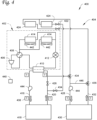
- Thermal system and hydronic system 400 includes thermal system 402 and hydronic system 404.
- Thermal system 402 includes a compressor 406, a flow reverser 408, a first heat exchanger 410, an expander 412, and one or more second heat exchanger(s) 414.
- the hydronic system 404 includes the first heat exchanger 410, a supply line 416 from the first heat exchanger 410 to a load 418, a return line 420 from the primary load 418 to the first heat exchanger 410.
- the hydronic system 404 further includes controllable valves 422, air-to-fluid heat exchangers 424, and bypass valve 426.
- Hydronic system 404 additionally includes secondary load supply line 428, secondary load 430, secondary load return line 432, cooling/defrost control valves 434 and heating control valve 436. Hydronic system 404 can further include temperature sensors 438 and controller 440. Thermal system and hydronic system 400 can also include fans 442. Pumps 444 can be included in the hydronic system 404.
- Thermal system and hydronic system 400 is configured such that thermal system 402 is operated to add or remove heat from a process fluid circulated within hydronic system 404.
- the process fluid can exchange heat with primary load 418 so as to service heating and/or cooling needs at the primary load 418.
- Thermal system 402 is a reversible thermal system configured to circulate a working fluid so as to add or remove heat from the process fluid.
- Thermal system 402 includes a compressor 406.
- Compressor 406 can be any suitable compressor for compressing the working fluid. In an embodiment, multiple compressors 406 can be provided as the compressor 406 as shown in Figure 4 .
- Compressed working fluid discharged from the compressor 406 is then directed to flow reverser 408.
- Flow reverser 408 is a flow control configured to control a direction of flow through the thermal system 402 by directing the discharge from the compressor 406 to either first heat exchanger 410 or the one or more second heat exchangers 414.
- the flow reverser 408 directs the discharge of the compressor 406 to first heat exchanger 410, and directs working fluid received from the one or more second heat exchangers 414 to the compressor 406.
- the flow reverser 408 directs the discharge of the compressor 406 to the one or more second heat exchangers 414, and directs working fluid received from the first heat exchanger 410 to the compressor 406.
- the first heat exchanger 410 is a heat exchanger configured to exchange heat between the working fluid and process fluid being circulated through the hydronic system 404.
- the first heat exchanger 410 operates as a condenser for the working fluid, where the working fluid rejects heat, thus heating the process fluid in the hydronic system 404.
- the first heat exchanger 410 operates as an evaporator, with the working fluid absorbing heat, thereby cooling the process fluid.
- An expander 412 is provided between the first heat exchanger 410 and the one or more second heat exchangers 414.
- the expander 412 can be any suitable expander capable of expanding received working fluid, such as, for example, an expansion valve, an expansion plate, an expansion vessel, one or more expansion orifices, or any other known suitable structure for expanding the working fluid.
- the expander 412 is an electronic expansion valve.
- Thermal system 402 further includes one or more second heat exchangers 414.
- the second heat exchanger(s) 414 are heat exchangers configured to exchange heat with an ambient environment or other suitable source/sink for heat.
- the one or more second heat exchangers 414 are outdoor heat exchangers configured to exchange heat with air in the ambient environment of thermal system 402.
- frost can build up on at least one of the one or more second heat exchangers 414 based on the ambient temperature and operations of the thermal system 402, for example when the thermal system is being operated to provide heating at ambient temperatures below freezing.
- the one or more second heat exchangers 414 operate as an evaporator, with the working fluid absorbing heat from the ambient environment.
- the one or more second heat exchangers 414 operate as a condenser for the working fluid, where the working fluid rejects heat to the ambient environment.
- Hydronic system 404 is configured to circulate the process fluid from the first heat exchanger 410, where the process fluid absorbs or rejects heat according to the operating mode of thermal system 402, and primary load 418, where the process fluid exchanges heat to provide heating or cooling to service the primary load 418. Hydronic system 404 is further configured to selectively circulate process fluid to a secondary load 430.
- the process fluid can be circulated between secondary load 430 and the air-to-fluid heat exchangers 424, such that the air-to-fluid heat exchangers are the heat source or heat sink supporting heating or cooling, respectively, of the secondary load 430.
- the process fluid can be driven to circulate by operation of a pumps 444.
- Pumps 444 can be included in the supply or return associated with the primary load 418, and also in the supply or return associated with the secondary load 430. In an embodiment, the pump 444 can be provided at a different position in the hydronic system 404. In an embodiment, multiple pumps 444 can be provided to circulate the process fluid in hydronic system 404.
- Hydronic system 404 includes the process fluid side of first heat exchanger 410, at which the process fluid absorbs heat from or rejects heat to the working fluid of thermal system 402.
- Hydronic system 416 includes a supply line 416 from the first heat exchanger 410 to the primary load 418, which conveys the process fluid to the primary load 418. In an embodiment, the pump 444 is disposed along the supply line 416.
- the primary load 418 can be any suitable heating and/or cooling load to be serviced by operation of thermal system and hydronic system 400.
- the load can be, as non-limiting examples, a heating and/or cooling load of a conditioned space, a heat exchanger of another thermal system in a cascade arrangement with the thermal system and hydronic system 400, or the like.
- Process fluid is returned from the primary load 418 by way of return line 420.
- Controllable valves 422 are provided to regulate flow of process fluid from the return line 420 to each of the air-to-fluid heat exchangers 424.
- Controllable valves 422 can be any suitable valves capable of providing a variable flow or preventing flow into the corresponding air-to-fluid heat exchanger 424.
- One controllable valve 422 can be provided for each of the air-to-fluid heat exchangers 424.
- the air-to-fluid heat exchangers 424 are one or more heat exchangers provided in proximity to the one or more second heat exchangers 414.
- the air-to-fluid heat exchanger 424 and the corresponding second heat exchanger 414 can be provided in a single multi-function heat exchange structure.
- one air-to-fluid heat exchanger 424 is provided for each of the one or more second heat exchangers 414.
- the air-to-fluid heat exchangers 424 can be in heat exchange relationships with the one or more second heat exchangers 414, either directly by having a portion in contact with the corresponding one or more second heat exchangers 414, or indirectly by way of the air at the air-to-fluid heat exchanger 424 and corresponding second heat exchanger 414, such as an airflow being driven by a corresponding fan 442.
- the process fluid can absorb or reject heat at the air-to-fluid heat exchangers 424, based on the ambient conditions and/or the temperature at the second heat exchanger 414.
- the process fluid that is heated or cooled by the absorption or rejection of heat, respectively, can be circulated to secondary load 430 to provide heating or cooling so as to service said secondary load 430.
- a bypass valve 426 is provided along the return line 420.
- the bypass valve 426 can regulate flow that passes through return line 420 without passing to the controllable valves 422 and thus bypasses the air-to-fluid heat exchangers 424.
- Secondary load supply line 428 is a fluid line configured to convey process fluid from the air-to-fluid heat exchangers 424 to the secondary load 430.
- Secondary load supply line 428 can extend from one of the load/defrost control valves 434 to the secondary load 430.
- Secondary load 430 can be a heating or cooling load capable of being serviced by the process fluid based on the range of temperatures that can be provided by exchange of heat at the air-to-fluid heat exchanger.
- the secondary load 430 can be a reheating load, a dehumidification load, a sensible heating load, a sensible cooling load, heating or cooling loads for specific portions of a conditioned space, pre-heating or pre-cooling loads, or the like.
- the secondary load 430 is an opposite type of load from the primary load 418.
- the primary load 418 is a heating load
- the secondary load 430 can be a cooling load, and vice versa.
- the secondary load 430 can be of the same heating or cooling type, but having different temperature requirements from the primary load 418.
- Secondary load return line 432 is a fluid line configured to convey process fluid from the secondary load 430 back to the air-to-fluid heat exchangers 424. Secondary load return line 432 can extend from the secondary load 430 to another of the load/defrost control valves 434.
- Load/defrost control valves 434 are a set of valves that can include two-way valves, three-way valves, and/or or assemblies of multiple valves, and that are configured to control the fluid connections of hydronic system 404 to control whether the air-to-fluid heat exchangers 424 are in communication with primary load 418 and first heat exchanger 410, or secondary load 430.
- load/defrost control valves 434 can be configured to block flow from the return line 420 from primary load 418 to the air-to-fluid heat exchangers 424 and vice versa, and to permit circulation of the process fluid between the air-to-fluid heat exchanger 424 and the secondary load 430 by way of the secondary load supply line 428 and secondary load return load 432.
- the load/defrost control valves can be configured to block flow of the process fluid into the secondary load supply line 428 and from secondary load return line 432, and to permit flow from the return line 420 from primary load 418 to the air-to-fluid heat exchangers 424 and back to return line 420.
- Heating control valve 436 can be provided to allow at least some of the process fluid being circulated to and from secondary load 430 to bypass the air-to-fluid heat exchangers 424.
- Heating control valve 436 can be a controllable three-way valve or an assembly including multiple valves that is configured to modulate a flow through one of secondary load return line 432 and allow the diversion of at least some of the flow through the secondary load return line 432 to the secondary load supply line 428, for example by way of a bypass line 446 or any other suitable fluid connection.
- Temperature sensors 438 can be provided in hydronic system 404.
- the temperature sensors 438 can be positioned to measure suitable temperatures for control of the hydronic system 404, for example a primary supply temperature in supply line 416, a primary return temperature in return line 420, a thermal system entering temperature at an inlet of the process fluid side of first heat exchanger 410, a thermal system leaving temperature at an outlet of the process fluid side of the first heat exchanger 410, a secondary load supply temperature in secondary load supply line 428, a secondary load return temperature in secondary load return line 432, and/or temperatures at air-to-fluid heat exchangers 424.
- the thermal system and hydronic system 400 can include a controller 440.
- the controller 440 is configured to control the controllable valves 422, bypass valve 426, load/defrost control valves 434, and/or heating control valve 436.
- the controller 440 can be configured to control the controllable valves 422, bypass valve 426, load/defrost control valves 434, and/or heating control valve 436, for example, through calls for heating or cooling at the secondary load, a call to perform a defrosting operation, to achieve particular target values for a least one of the temperatures measured by the temperature sensors 438, or any other suitable basis for controlling the controllable valves 422, bypass valve 426, load/defrost control valves 434, and/or heating control valve 436.
- Fans 442 can be provided at the one or more second heat exchangers 414 and the corresponding air-to-fluid heat exchangers 424.
- the fans 442 can be controllable fans having variable speed.
- the fans 442 can be reversible such that air can be pulled through or pushed into the second heat exchanger 414 and air-to-fluid heat exchanger 424.
- the reversibility of the fan 442 can allow either of second heat exchanger 414 or air-to-fluid heat exchanger 424 to be the first of the respective heat exchangers 414, 424, that first receives the ambient air being driven or drawn by the fan 442.
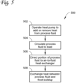
- Figure 5 shows a method of operating a thermal system and a hydronic system to defrost the thermal system.
- Method 500 includes operating a thermal system to add or remove heat from the process fluid 502, circulating the process fluid to a load 504, directing at least a portion of the process fluid to an air-to-fluid heat exchanger 506, and exchanging heat between process fluid at the air-to-fluid heat exchanger and frost buildup at an outdoor heat exchanger of the thermal system 508.
- the thermal system is operated to add or remove heat from the process fluid at 502.
- Operation to add or remove heat at 502 can include compressing a working fluid, condensing the working fluid at one heat exchanger, expanding the working fluid, and evaporating the working fluid at another heat exchanger.
- the process fluid can be heated at a heat exchanger when the working fluid is being condensed, or cooled when the working fluid is being evaporated at the heat exchanger.
- frost can form on a heat exchanger where the working fluid exchanges heat with an ambient environment, such as the one or more second heat exchangers 114 of thermal system 102, particularly when the thermal system is operated to add heat to the process fluid during a heating operation at cold ambient conditions.
- the process fluid After the process fluid has been heated or cooled at 502, it is circulated to a load at 504 to provide heating or cooling to said load.
- the load can be, for example, a heating load or a cooling load of a conditioned space, a cascade heat exchanger of another thermal system circuit, or the like.
- the process fluid can then pass back from the load to the thermal system to again be heated or cooled at 502.
- At least a portion of the process fluid is directed to an air-to-fluid heat exchanger at 506.
- the defrost operation at 506 can be performed based on a command from a controller.
- the portion of the process fluid can be sourced from a supply line from the thermal system to the load, or a return line from the load to the thermal system.
- the direction of the process fluid to the air-to-fluid heat exchanger at 506 can be performed using valves controlled by the controller.
- the portion of the process fluid can be directed by suitable valves and piping to pass to an air-to-fluid heat exchanger.
- the diverted working fluid exchanges heat with frost buildup at an outdoor heat exchanger of the thermal system 508, such as any of second heat exchangers 114, 214, 314, or 414 as described above and shown in Figures 1-4 .
- the air-to-fluid heat exchanger is positioned such that it can exchange heat with the outdoor heat exchanger of the thermal system, either directly or by way of air between the air-to-fluid heat exchanger and the outdoor heat exchanger.
- the air can, for example, be drawn or driven over both the air-to-fluid heat exchanger and the outdoor heat exchanger by one or more fans.
- the diverted working fluid is at a relatively higher temperature than the freezing point of water, and thus rejects heat to the frost buildup, thus melting the frost buildup off of the outdoor heat exchanger.
- Process fluid leaving the air-to-fluid heat exchanger can rejoin the process fluid being circulated between the thermal system and the load, for example being returned to the side from which the process fluid was obtained at 506.
- Figure 6 shows a method of operating a thermal system and a hydronic system to support simultaneous heating and cooling operations.
- Method 600 includes operating a first thermal system to add or remove heat from a first quantity of process fluid 602, circulating the first quantity of process fluid to a primary load 604, directing a second quantity of the process fluid to an air-to-fluid heat exchanger 606, and directing the second quantity of the process fluid from the air-to-fluid heat exchanger to a secondary load 608.
- Method 600 can be performed using, for example, thermal system and hydronic system 400 as described above and shown in Figure 4 .
- the thermal system is operated to add or remove heat from a first portion of the process fluid at 602.
- the first portion of the process fluid is the portion circulating between the thermal system and the primary load.
- the first portion of the process fluid can be kept separate from a second portion of the process fluid that is circulated between the air-to-fluid heat exchanger and a secondary load.
- valves in the hydronic system can be closed to prevent flow between the part of the hydronic system circulating process fluid from the thermal system to the primary load and the part of the hydronic system circulating process fluid from the air-to-fluid heat exchanger to the secondary load.
- the operation to add or remove heat at 602 can include compressing a working fluid, condensing the working fluid at one heat exchanger, expanding the working fluid, and evaporating the working fluid at another heat exchanger.
- the first portion of the process fluid can be heated at a heat exchanger when the working fluid is being condensed, or cooled when the working fluid is being evaporated at the heat exchanger.
- the first quantity of process fluid After the first quantity of process fluid has been heated or cooled at 602, it is circulated to a primary load at 604 to provide heating or cooling to said load.
- the load can be, for example, a heating load or a cooling load of a conditioned space, or the like.
- the first portion of the process fluid can then pass back from the load to the thermal system to again be heated or cooled at 602.
- a second quantity of the process fluid is directed to an air-to-fluid heat exchanger 606.
- the second quantity of the process fluid is a portion of the process fluid in the hydronic system that is circulated between the air-to-fluid heat exchanger and the secondary load.
- the second quantity of the process fluid can be kept separate from the first quantity of the process fluid, for example due to closure of valves included in the hydronic system.
- the second quantity of process fluid can absorb or reject heat, depending on the temperature of the second quantity of the process fluid and ambient conditions, heat being absorbed or rejected by the outdoor heat exchanger of the thermal system circuit, operation of one or more fans directing airflow over the outdoor heat exchanger and/or the air-to-fluid heat exchanger, or the like.
- fans can be controlled to achieve a certain temperature for the second quantity of the process fluid as it leaves the air-to-fluid heat exchanger.
- the second quantity of the process fluid is directed from the air-to-fluid heat exchanger to a secondary load at 608.
- the secondary load can be a heating or cooling load capable of being serviced by the process fluid based on the range of temperatures that can be provided by exchange of heat at the air-to-fluid heat exchanger.
- the secondary load can be a reheating load, a dehumidification load, a sensible heating load, a sensible cooling load, heating or cooling loads for specific portions of a conditioned space, or the like.
- the secondary load is an opposite type of load from the primary load. For example, where the primary load is a heating load, the secondary load can be a cooling load, and vice versa.
- the secondary load can be of the same heating or cooling type, but having different temperature requirements from the primary load.
- the second quantity of the process fluid can absorb or reject heat based on the relative temperature difference between the second quantity of process fluid and the secondary load.
- the second quantity of process fluid can circulate back to the air-to-fluid heat exchanger to absorb or reject heat at 606 to continue servicing the secondary load at 608.
- Figure 7 shows a method of operating a thermal system and a hydronic system to support pre-heating or pre-cooling.
- Method 700 includes operating a first thermal system to add or remove heat from the process fluid 702, circulating the process fluid to a load 704, directing at least a portion of the process fluid to an air-to-fluid heat exchanger 706, and exchanging heat between process fluid at the air-to-fluid heat exchanger and the ambient environment at an outdoor heat exchanger of the first thermal system 708 to pre-heat or pre-cool the process fluid.
- Method 700 can be performed under certain conditions, when heating or cooling of process fluid at the air-to-fluid heat exchanger is capable of supporting the heating or cooling operation of the thermal system. This determination can be based on one or more of the ambient temperature, the supply temperature of the process fluid, the return temperature of the process fluid, predicted heating or cooling at the air-to-fluid heat exchanger, temperature at the outdoor heat exchanger of the thermal system, temperature targets for the supply, efficiency data for the thermal system circuit, and the like.
- a thermal system is operated to add or remove heat from the process fluid at 702.
- Operation to add or remove heat at 702 can include compressing a working fluid, condensing the working fluid at one heat exchanger, expanding the working fluid, and evaporating the working fluid at another heat exchanger.
- the process fluid can be heated at a heat exchanger when the working fluid is being condensed, or cooled when the working fluid is being evaporated at the heat exchanger.
- the process fluid After the process fluid has been heated or cooled at 702, it is circulated to a load at 704 to provide heating or cooling to said load.
- the load can be, for example, a heating load or a cooling load of a conditioned space, or the like.
- the first portion of the process fluid can then pass back from the load to the thermal system to again be heated or cooled at 702.
- the process fluid When pre-heating or pre-cooling according to method 700, at least a portion of the process fluid is directed to an air-to-fluid heat exchanger at 706.
- the process fluid can be sourced from a supply line or a return line, depending on the piping arrangement and/or whether the process fluid is to be pre-heated or pre-cooled.
- the direction of the portion of process fluid to the air-to-fluid heat exchanger at 706 can be performed by operation of one or more valves by a controller.
- the process fluid is sourced from the return line.
- the amount of process fluid directed to the air-to-fluid heat exchanger at 706 is controlled based on the ability to achieve a temperature that supports the heating or cooling operation being performed by the thermal system adding or removing heat from the process fluid at 702.
- Heat is exchanged between the process fluid at the air-to-fluid heat exchanger and the ambient environment at an outdoor heat exchanger of the first thermal system at 708 to pre-heat or pre-cool the process fluid.
- the process fluid at the air-to-fluid heat exchanger can reject heat at the air-to-fluid heat exchanger at 708 based on the ambient conditions, operation of a fan, temperatures at the outdoor heat exchanger of the first thermal system, and the like, thereby cooling the process fluid to support operation of the thermal system to cool the load.
- the process fluid at the air-to-fluid heat exchanger can absorb heat at the air-to-fluid heat exchanger at 708 based on the ambient conditions, operation of a fan, temperatures at the outdoor heat exchanger of the first thermal system, and the like, thereby heating the process fluid to support operation of the thermal system to heat the load.
- the process fluid a.
- the pre-heated or pre-cooled process fluid can join the remainder of the process fluid circulated between the thermal system and the load so as to be heated or cooled by the thermal system at 702 and service the heating or cooling load at 704.
- Figure 8 shows a method of operating a thermal system and a hydronic system to support cascade operation.
- Method 800 includes operating a first thermal system to add or remove heat from the process fluid 802, circulating the process fluid to a cascade heat exchanger of a second thermal system 804, directing the at least a portion of the process fluid to an air-to-fluid heat exchanger 806, and exchanging heat between process fluid and an environment at the air-to-fluid heat exchanger 808.
- a first thermal system is operated to add or remove heat from the process fluid 802
- the first thermal system can be a thermal system that is in a cascade arrangement with a second thermal system, configured to supply heating or cooling to support operation of the second thermal system.
- Operation to add or remove heat at 802 can include compressing a working fluid, condensing the working fluid at one heat exchanger, expanding the working fluid, and evaporating the working fluid at another heat exchanger.
- the process fluid can be heated at a heat exchanger when the working fluid is being condensed, or cooled when the working fluid is being evaporated at the heat exchanger.
- the process fluid is circulated from the first thermal system to a cascade heat exchanger of a second thermal system 804.
- the process fluid exchanges heat with a working fluid of the second thermal system.
- the first thermal system heats the process fluid at 802, with the process fluid used as a heat source to support heating operations of the second thermal system.
- the first thermal system cools the process fluid at 802, with the process fluid used as a heat sink to support cooling operations of the second thermal system.
- a portion of the process fluid is directed to an air-to-fluid heat exchanger 806.
- the portion of the process fluid directed to the air-to-fluid heat exchanger can be an amount selected to balance the operations of the first and second thermal systems, for example to achieve a target supply temperature to the second thermal system and/or a target return temperature to the first thermal system.
- the amount of process fluid that is directed to the air-to-fluid heat exchanger can be based on one or more of the ambient temperature, the supply temperature of the process fluid, the return temperature of the process fluid, predicted heating or cooling at the air-to-fluid heat exchanger, temperature at the outdoor heat exchanger of the first thermal system, supply and/or return temperature targets, efficiency data for the first and/or second thermal system, and the like.
- the amount can be determined by a controller.
- a controller can control valves of the hydronic system to direct the amount of the process fluid to the air-to-fluid heat exchanger at 806.
- the controller can control valves of the hydronic system so as to achieve a target fluid inlet temp from the first thermal system to the cascade heat exchanger.
- Heat is exchanged between the process fluid and the environment at the air-to-fluid heat exchanger at 808. Based on the temperature of the process fluid and the ambient temperature, temperature at the outdoor heat exchanger of the first thermal system, and/or operation of fans, the process fluid absorbs or rejects heat. The process fluid then joins the process fluid being circulated between the first thermal system and the second thermal system, thereby affecting the supply and/or return temperatures at the respective thermal systems.
- the effects on the supply and/or return temperatures can be controlled, for example by controlling the portion of the process fluid that is directed to the air-to-fluid heat exchanger at 806, to allow one or both of the first and second thermal systems to be operated at more efficient operational settings without creating imbalances in the heating or cooling of the process fluid between the first and second thermal systems.
- FIG. 9 shows a schematic of a heating and cooling system according to an embodiment.
- Heating and cooling system 900 includes thermal system 902.
- the thermal system 902 includes one or more compressors 904, at least one first heat exchanger 906, at least one second heat exchanger 908, and at least one third heat exchanger 910.
- Thermal system 902 includes one or more expanders 912 and valves 914.
- Heating and cooling system 900 further includes first process fluid circuit 916.
- First process fluid circuit 916 can be for heating, and includes first supply line 918, first load 920, and first return line 922.
- One or more pumps 924 can be included in first process fluid circuit 916.
- First process fluid circuit 916 can further include fluid lines 926 and valves 928 configured to control flow of process fluid from first process fluid circuit 916 to one or more air-to-fluid heat exchangers 930.
- Heating and cooling system 900 also includes second process fluid circuit 932, such as for cooling.
- Second process fluid circuit 932 includes second supply line 934, second load 936, and second return line 938.
- Second process fluid circuit 932 can further include one or more pumps 940.
- the second process fluid circuit 932 can also further include fluid lines 942 and valves 944 configured to control flow of process fluid from the second process fluid circuit 932 to the one or more air-to-fluid heat exchangers 930.
- Thermal system 902 can be, for example, a combined heating and cooling system capable of heating, cooling, and simultaneous heating and cooling operations.
- Thermal system 902 can be, for example, a multi-pipe heating and cooling system such as a four-pipe heating and cooling system.
- Thermal system 902 circulates a working fluid, such as any suitable refrigerant, to provide the heating, cooling, or simultaneous heating and cooling.
- Thermal system 902 includes one or more compressors 904 configured to compress the working fluid.
- the one or more compressors 904 can be any suitable type of compressor, or combinations thereof. Where the one or more compressors 904 includes multiple compressors, the compressors can be in series, in parallel, or in a combination thereof.
- Thermal system 902 includes at least one first heat exchanger 906.
- Each of the at least one first heat exchanger(s) 906 is configured to exchange heat between the working fluid and a first process fluid of first process fluid circuit 916.
- Each of the at least one first heat exchanger(s) 906 can receive the first process fluid from the first return line 922, pass the first process fluid through the first heat exchanger 906 so as to exchange heat between the working fluid and the first process fluid, and direct the first process fluid into first supply line 918 to service first load 920.
- Thermal system 902 further includes at least one second heat exchanger 908.
- Each of the at least one second heat exchanger(s) 908 is configured to exchange heat between the working fluid and the second process fluid of second process fluid circuit 932.
- Each of the at least one second heat exchanger(s) 908 can receive the second process fluid from the second return line 938, pass the first process fluid through the second heat exchanger 908 so as to exchange heat between the working fluid and the second process fluid and direct the first process fluid into second supply line 934 to service second load 936.
- Thermal system 902 additionally includes at least one third heat exchanger 910.
- Each of the at least one third heat exchanger(s) are configured to exchange heat between the working fluid and an ambient environment of said third heat exchanger 910.
- the third heat exchanger(s) 910 can be configured such that the working fluid can absorb heat or reject heat, based on the ambient conditions and the temperature of the working fluid based when it is provided at third heat exchanger 910.
- Thermal system 902 includes one or more expanders 912 disposed along the fluid circuit that the working fluid is circulated through. At least one of the one or more expanders 912 can be included in the flow path of the working fluid from the compressor when the working fluid is circulated through thermal system 902.
- the expander(s) 912 can include any suitable expander capable of expanding received working fluid, such as, for example, an expansion valve, an expansion plate, an expansion vessel, one or more expansion orifices, combinations thereof, or any other known suitable structure(s) for expanding the working fluid.
- valves 914 are provided on the fluid lines of thermal system 902.
- the valves 914 are configured to control flow through the respective connected fluid lines such that two of the first heat exchanger(s) 906, second heat exchanger(s) 908, and third heat exchanger(s) 910 are included in the flow path for the working fluid and the other of the first heat exchanger(s) 906, second heat exchanger(s) 908, and third heat exchanger(s) 910 are excluded from the flow path for the working fluid.
- valves 914 can be configured to include the first heat exchanger(s) 906 and the second heat exchanger(s) 908 and exclude the third heat exchanger(s) 910 when the thermal system 902 is in a mode where both first load 920 and second load 936 are serviced, such as a combined heating and cooling mode.
- the valves 914 can be configured to include the first heat exchanger(s) 906 and the third heat exchanger(s) 910 and exclude the second heat exchanger(s) 908 when the thermal system 902 is in a mode where first load 920 is serviced, such as a heating mode.
- valves 914 can be configured to include the second heat exchanger(s) 908 and the third heat exchanger(s) 910 and exclude the first heat exchanger(s) 906 when the thermal system 902 is in a mode where second load 936 is serviced, such as a cooling mode.
- First process fluid circuit 916 is configured to circulate a first process fluid so as to service first load 920.
- the first load 920 is a heating load
- the first process fluid circuit 916 is configured such that the first process fluid absorbs heat at first heat exchanger(s) 906 and rejects heat at first load 920 to provide heating at first load 920.
- First process fluid circuit 916 includes a first supply line 918 configured to convey the first process fluid from the first heat exchanger(s) 906 to the first load 920. The process fluid exchanges heat at the first load 920, and is returned from the first load 920 to the first heat exchanger(s) 906 by way of the first return line 922.
- One or more pumps 924 can be included in first process fluid circuit 916, for example on first supply line 918 or first return line 922 to drive the circulation of the first process fluid through first process fluid 916.
- First process fluid circuit 916 can include fluid lines 926 configured to direct a portion of the first process fluid to at least some of the one or more air-to-fluid heat exchangers 930.
- the portion of the flow directed to the air-to-fluid heat exchanger(s) 930 can be diverted and controlled by valves 928 provided at suitable positions in first process fluid circuit 916.
- valves 928 and fluid lines 926 are configured such that the first process fluid provided to the air-to-fluid heat exchanger(s) 930 is obtained from and returned to the first supply line 918, however in an alternative embodiment, the valves 928 and fluid line 926 can instead be configured such that the first process fluid provided to the air-to-fluid heat exchanger(s) 930 is obtained from and returned to first return line 922.
- One or more air-to-fluid heat exchangers 930 in proximity to the one or more third heat exchangers 910, such that the air-to-fluid heat exchangers 930 can exchange heat between one or both of the first and second process fluids and the ambient environment of at least one of the third heat exchangers 910.
- the exchange of heat at the air-to-fluid heat exchangers 930 can be, for example, to pre-heat or pre-cool one or both of the first and second process fluids, to defrost said at least one of the third heat exchangers 910, or any other suitable result of such heat exchange as provided herein.
- a plurality of the air-to-fluid heat exchangers 930 are provided, with some of the plurality of air-to-fluid heat exchangers 930 configured to receive the first process fluid and others of the plurality of air-to-fluid heat exchangers 930 configured to receive the second process fluid.
- the air-to-fluid heat exchangers 930 can be configured to receive either of the first process fluid or the second process fluid.
- Second process fluid circuit 932 is configured to circulate a second process fluid so as to service second load 936.
- the second load 936 is a cooling load
- the second process fluid circuit 932 is configured such that the second process fluid rejects heat at second heat exchanger(s) 908 and absorbs heat from second load 936 to provide heating at second load 936.
- Second process fluid circuit 932 includes a second supply line 934 configured to convey the second process fluid from the second heat exchanger(s) 908 to the second load 936. The process fluid exchanges heat at the second load 936, and is returned from the second load 936 to the second heat exchanger(s) 908 by way of the second return line 938.
- One or more pumps 940 can be included in second process fluid circuit 932, for example on second supply line 934 or second return line 938 to drive the circulation of the second process fluid through second process fluid 932.
- Second process fluid circuit 932 can include fluid lines 942 configured to direct a portion of the second process fluid to at least some of the one or more air-to-fluid heat exchangers 930.
- said at least some of the one or more air-to-fluid heat exchangers 930 connected to the second process fluid circuit 932 are separate from the one or more air-to-fluid heat exchangers 930 connected to the first process fluid circuit 916.
- the portion of the flow directed to the air-to-fluid heat exchanger(s) 930 can be diverted and controlled by valves 944 provided at suitable positions in second process fluid circuit 932.
- valves 944 and fluid lines 942 are configured such that the second process fluid provided to the air-to-fluid heat exchanger(s) 930 is obtained from and returned to the second supply line 934, however in an alternative embodiment, the valves 944 and fluid line 942 can instead be configured such that the second process fluid provided to the air-to-fluid heat exchanger(s) 930 is obtained from and returned to second return line 938.
- One or more fans 946 can be provided at some or all of the air-to-fluid heat exchangers 930 and/or corresponding third heat exchangers 910.
- the fans 946 can be controllable fans having variable speed.
- the fans 946 can be reversible such that air can be pulled through or pushed into the third heat exchanger 910 and corresponding air-to-fluid heat exchanger 930.
- the reversibility of the fan 946 can allow either of third heat exchanger 910 or air-to-fluid heat exchanger 930 to be the first of the respective heat exchangers 910, 930, that first receives the ambient air being driven or drawn by the fan 946.
- a method comprising directing a portion of a flow of process fluid from a hydronic system to a heat exchanger, the heat exchanger configured to exchange heat between the process fluid and an outdoor heat exchanger of a working fluid circuit of a thermal system.
- Aspect 2 The method of according to aspect 1, wherein the process fluid rejects heat to the outdoor heat exchanger.
- Aspect 3 The method according to aspect 2, further comprising determining a defrosting operation of the heat exchanger, and where the directing the portion of the flow of process fluid from the hydronic system to the heat exchanger is performed when the defrosting operation is determined.
- Aspect 4 The method according to aspect 2 or aspect 3, wherein the flow of process fluid, after leaving the heat exchanger, is directed to a cooling load of the hydronic system.
- Aspect 5 The method according to any of aspects 1-4, wherein the process fluid absorbs heat from the outdoor heat exchanger.
- Aspect 6 The method according to aspect 5, wherein the flow of process fluid, after leaving the heat exchanger, is directed to a heating load of the hydronic system.
- Aspect 7 The method according to any of aspects 1-6, wherein the process fluid is circulated between the thermal system and a second thermal system in a cascade system, and the process fluid rejects heat to the outdoor heat exchanger such that the process fluid is provided to the second thermal system at a target temperature.
- Aspect 8 The method according to any of aspects 1-7, wherein the thermal system is selected from the group consisting of a heat pump, a chiller, and a combined heating and cooling apparatus.
- a thermal system and hydronic system comprising:
- Aspect 10 The thermal system and hydronic system according to aspect 9, further comprising:
- Aspect 11 The thermal system and hydronic system according to aspect 10, wherein the secondary load is a cooling load.
- Aspect 12 The thermal system and hydronic system according to aspect 10, wherein the secondary load is a heating load.
- Aspect 13 The thermal system and hydronic system according to any of aspects 9-12, wherein the load is a second thermal system, the second thermal system in a cascade relationship with the first thermal system.
- Aspect 14 The thermal system and hydronic system according to any of aspects 9-13, further comprising a controller configured to determine operation in a defrost mode, and to control at least one of the one or more valves to allow flow of the process fluid to the air-to-fluid heat exchanger.
- Aspect 15 The thermal system and hydronic system according to any of aspects 9-14, further comprising a fan configured to direct airflow over the first heat exchanger and the air-to-fluid heat exchanger.
- Aspect 16 The thermal system and hydronic system according to aspect 15, wherein the fan is reversible.
- Aspect 17 The thermal system and hydronic system according to any of aspects 9-16, wherein the thermal system further comprises a third heat exchanger, the third heat exchanger configured to exchange heat between the working fluid and a second process fluid of a second hydronic system, the second hydronic system configured to circulate the second process fluid to a second load.
- the thermal system further comprises a third heat exchanger, the third heat exchanger configured to exchange heat between the working fluid and a second process fluid of a second hydronic system, the second hydronic system configured to circulate the second process fluid to a second load.
- Aspect 18 The thermal system and hydronic system according to aspect 17, wherein the second hydronic system is configured to selectively provide the second process fluid to the air-to-fluid heat exchanger.
- Aspect 19 The thermal system and hydronic system according to aspect 17, further comprising at least one second air-to-fluid heat exchanger, wherein the second hydronic system is configured to selectively provide the second process fluid to the least one second air-to-fluid heat exchanger.
- Aspect 20 The thermal system and hydronic system according to any of aspects 17-19, wherein one of the load and the second load is a heating load, and the other of the load and the second load is a cooling load.
Landscapes
- Engineering & Computer Science (AREA)
- Mechanical Engineering (AREA)
- General Engineering & Computer Science (AREA)
- Physics & Mathematics (AREA)
- Thermal Sciences (AREA)
- Chemical & Material Sciences (AREA)
- Combustion & Propulsion (AREA)
- Air Conditioning Control Device (AREA)
Abstract
Process fluid from a hydronic system can be directed to an air-to-fluid heat exchanger in a heat exchange relationship with an outdoor heat exchanger of a thermal system connected to the hydronic system. The flow from the hydronic system to the air-to-fluid heat exchanger can be controlled using one or more valves. The process fluid at the air-to-fluid heat exchanger can defrost the outdoor heat exchanger, be used for free heating or cooling by being directed to a secondary load, or be used for balancing of cascade systems. A reversible fan can be provided at the outdoor heat exchanger and the air-to-fluid heat exchanger to facilitate these operations.
Description
- This disclosure is directed to heating, ventilation, air conditioning, and refrigeration (HVACR) systems including a thermal system circuit and a hydronic system, where the hydronic system can exchange heat with an outdoor heat exchanger of the thermal system circuit.
- At some ambient conditions, thermal systems can experience a buildup of ice on an outdoor heat exchanger. The ice buildup can be removed by operating in a defrost mode, where hot working fluid is directed to the outdoor heat exchanger to melt the ice. This requires operation in a specific mode and can disrupt heating operations of the thermal system and reduce heating efficiency. Additionally, cascade thermal system systems can experience imbalances in the heat generation of the system, causing one or both of the thermal systems in the cascade arrangement to be operated at less efficient operational conditions.
- This disclosure is directed to heating, ventilation, air conditioning, and refrigeration (HVACR) systems including a thermal system circuit and a hydronic system, where the hydronic system can exchange heat with an outdoor heat exchanger of the thermal system circuit.
- By allowing heat exchange between the hydronic system and one or more outdoor heat exchangers of a thermal system circuit, various functionalities can be provided with no or reduced impact on the operation of the thermal system circuit. The functionalities can include, for example, defrosting of the one or more outdoor heat exchangers, capturing heating or cooling to enable simultaneous servicing of heating and cooling modes, pre-heating or pre-cooling of fluid in the hydronic system, and/or supporting cascade operations to boost capacity. In some embodiments, the fluid of the hydronic system exchanges heat at the one or more outdoor heat exchangers can be selectively obtained from or returned to either of the return line or the supply line, further enhancing control of these capabilities. Selectively sourcing and/or returning fluid from either the return line or the supply line can enable some functionalities and/or improve response to various conditions including but not limited to operating modes, heating and cooling demands, ambient conditions, combinations and/or relationships thereof, and the like.
- In an embodiment, a method includes directing a portion of a flow of process fluid from a hydronic system to a heat exchanger, the heat exchanger configured to exchange heat between the process fluid and an outdoor heat exchanger of a working fluid circuit of a thermal system.
- In an embodiment, the process fluid rejects heat to the outdoor heat exchanger. In an embodiment, the method further includes determining a defrosting operation of the heat exchanger, and where the directing the portion of the flow of process fluid from the hydronic system to the heat exchanger is performed when the defrosting operation is determined. In an embodiment, the flow of process fluid, after leaving the heat exchanger, is directed to a cooling load of the hydronic system.
- In an embodiment, the process fluid absorbs heat from the outdoor heat exchanger. In an embodiment, the flow of process fluid, after leaving the heat exchanger, is directed to a heating load of the hydronic system.
- In an embodiment, the process fluid is circulated between the thermal system and a second thermal system in a cascade system, and the process fluid rejects heat to the outdoor heat exchanger such that the process fluid is provided to the second thermal system at a target temperature.
- In an embodiment, the thermal system is selected from the group consisting of a heat pump, a chiller, and a combined heating and cooling apparatus.
- In an embodiment, a thermal system and hydronic system includes a thermal system configured to circulate a working fluid. The thermal system includes a compressor, a flow reverser, a first heat exchanger configured to exchange heat between the working fluid and an ambient environment, an expander, and a second heat exchanger configured to exchange heat between the working fluid and a process fluid. A hydronic system is configured to circulate the process fluid, The hydronic system includes a supply line configured to convey the process fluid from the second heat exchanger to a load, a return line configured to convey the process fluid from the load to the second heat exchanger, an air-to-fluid heat exchanger configured to exchange heat between the process fluid and the ambient environment at the first heat exchanger, and one or more valves configured to regulate flow of the process fluid to the air-to-fluid heat exchanger.
- In an embodiment, the thermal system and hydronic system further includes a secondary load supply line configured to convey the process fluid from the air-to-fluid heat exchanger to a secondary load, a secondary load return line configured to convey the process fluid from the secondary load to the air-to-fluid heat exchanger, one or more valves configured to regulate flow of the process fluid from the air-to-fluid heat exchanger to the secondary load supply line, and one or more valves configured to regulate flow of the process fluid from the secondary load return line to the air-to-fluid heat exchanger. In an embodiment, the secondary load is a cooling load. In an embodiment, the secondary load is a heating load.
- In an embodiment, the load is a second thermal system, the second thermal system in a cascade relationship with the first thermal system. In an embodiment, the thermal system and hydronic system further includes a controller configured to determine operation in a defrost mode, and to control at least one of the one or more valves to allow flow of the process fluid to the air-to-fluid heat exchanger.
- In an embodiment, the thermal system and hydronic system further includes a fan configured to direct airflow over the first heat exchanger and the air-to-fluid heat exchanger. In an embodiment, the fan is reversible.
- In an embodiment, the thermal system further includes a third heat exchanger, the third heat exchanger configured to exchange heat between the working fluid and a second process fluid of a second hydronic system, the second hydronic system configured to circulate the second process fluid to a second load. In an embodiment, the second hydronic system is configured to selectively provide the second process fluid to the air-to-fluid heat exchanger. In an embodiment, the thermal system and hydronic system further includes at least one second air-to-fluid heat exchanger, wherein the second hydronic system is configured to selectively provide the second process fluid to the least one second air-to-fluid heat exchanger. In an embodiment, one of the load and the second load is a heating load, and the other of the load and the second load is a cooling load.
-
-
Figure 1 shows a schematic of a thermal system and a hydronic system according to an embodiment. -
Figure 2 shows a schematic of a thermal system and a hydronic system according to an embodiment. -
Figure 3 shows a schematic of a thermal system and a hydronic system according to an embodiment. -
Figure 4 shows a schematic of a thermal system and a hydronic system according to an embodiment. -
Figure 5 shows a method of operating a thermal system and a hydronic system to defrost the thermal system. -
Figure 6 shows a method of operating a thermal system and a hydronic system to support simultaneous heating and cooling operations. -
Figure 7 shows a method of operating a thermal system and a hydronic system to support pre-heating or pre-cooling. -
Figure 8 shows a method of operating a thermal system and a hydronic system to support cascade operation. -
Figure 9 shows a schematic of a heating and cooling system according to an embodiment. - This disclosure is directed to heating, ventilation, air conditioning, and refrigeration (HVACR) systems including a thermal system circuit and a hydronic system, where a hydronic system can exchange heat with outdoor heat exchanger of the thermal system.
- As used herein, "hydronic system" refers to any system that circulates any suitable process fluid to convey heat from one or more heat sources to one or more heat sinks. Process fluids that can be used in hydronic systems as discussed herein include, but are not limited to water, glycol, blends thereof, and the like.
-
Figure 1 shows a schematic of a thermal system and a hydronic system according to an embodiment. Thermal system andhydronic system 100 includesthermal system 102 andhydronic system 104.Thermal system 102 includes acompressor 106, aflow reverser 108, afirst heat exchanger 110, anexpander 112, and one or moresecond heat exchangers 114. Thehydronic system 104 includes thefirst heat exchanger 110, asupply line 116 from thefirst heat exchanger 110 to aload 118, areturn line 120 from theload 118 to thefirst heat exchanger 110. Thehydronic system 104 further includescontrollable valves 122, air-to-fluid heat exchangers 124, andbypass valve 126.Hydronic system 104 can further includetemperature sensors 128 andcontroller 130. Thermal system andhydronic system 100 can also includefans 132. Pump 134 can be included in thehydronic system 104. - Thermal system and
hydronic system 100 is configured such thatthermal system 102 is operated to add or remove heat from a process fluid circulated withinhydronic system 104. In embodiments, thethermal system 102 can be a heat pump, a chiller, a combined heating and cooling system such as a multi-pipe heating and cooling system, or the like. The process fluid can exchange heat withload 118 so as to service heating and/or cooling needs at theload 118. -
Thermal system 102 is configured to circulate a working fluid so as to add or remove heat from the process fluid. In the embodiment shown inFigure 1 ,thermal system 102 is a reversible heat pump. In other embodiments,thermal system 102 can instead be any other suitable thermal system for heating or cooling a process fluid by way of circulation of a working fluid.Thermal system 102 includes acompressor 106.Compressor 106 can be any suitable compressor for compressing the working fluid. In an embodiment,multiple compressors 106 can be provided as thecompressor 106 as shown inFigure 1 . Compressed working fluid discharged from thecompressor 106 is then directed to flowreverser 108.Flow reverser 108 is a flow control configured to control a direction of flow through thethermal system 102 by directing the discharge from thecompressor 106 to eitherfirst heat exchanger 110 or the one or moresecond heat exchangers 114. In the heating mode, theflow reverser 108 directs the discharge of thecompressor 106 tofirst heat exchanger 110, and directs working fluid received from the one or moresecond heat exchangers 114 to thecompressor 106. In the cooling mode, theflow reverser 108 directs the discharge of thecompressor 106 to the one or moresecond heat exchangers 114, and directs working fluid received from the first heat exchanger to thecompressor 106. - The
first heat exchanger 110 is a heat exchanger configured to exchange heat between the working fluid and process fluid being circulated through thehydronic system 104. In the heating mode, thefirst heat exchanger 110 operates as a condenser for the working fluid, where the working fluid rejects heat, thus heating the process fluid in thehydronic system 104. In the cooling mode, thefirst heat exchanger 110 operates as an evaporator, with the working fluid absorbing heat, thereby cooling the process fluid. - An
expander 112 is provided between thefirst heat exchanger 110 and the one or moresecond heat exchangers 114. Theexpander 112 can be any suitable expander capable of expanding received working fluid, such as, for example, an expansion valve, an expansion plate, an expansion vessel, one or more expansion orifices, or any other known suitable structure for expanding the working fluid. In an embodiment, theexpander 112 is an electronic expansion valve. -
Thermal system 102 further includes one or moresecond heat exchangers 114. The second heat exchanger(s) 110 are heat exchangers configured to exchange heat with an ambient environment or other suitable source/sink for heat. In an embodiment, the one or moresecond heat exchangers 114 are outdoor heat exchangers configured to exchange heat with air in the ambient environment ofthermal system 102. In an embodiment, frost can build up on at least one of the one or moresecond heat exchangers 114 based on the ambient temperature and operations of thethermal system 102, for example when thethermal system 102 is being operated to provide heating at ambient temperatures below freezing. In the heating mode, the one or moresecond heat exchangers 114 operate as an evaporator, with the working fluid absorbing heat from the ambient environment. In the cooling mode, the one or moresecond heat exchangers 114 operate as a condenser for the working fluid, where the working fluid rejects heat to the ambient environment. -
Hydronic system 104 is configured to circulate the process fluid from thefirst heat exchanger 110, where the process fluid absorbs or rejects heat according to the operating mode ofthermal system 102, and load 118, where the process fluid exchanges heat to provide heating or cooling to service theload 118. Inhydronic system 104, the process fluid can be driven to circulate by operation of apump 134 in some examples. In an embodiment, thepump 134 can be provided at a different position in thehydronic system 104. In an embodiment,multiple pumps 134 can be provided to circulate the process fluid inhydronic system 104.Hydronic system 104 includes the process fluid side offirst heat exchanger 110, at which the process fluid absorbs heat from or rejects heat to the working fluid ofthermal system 102.Hydronic system 104 includes asupply line 116 from thefirst heat exchanger 110 to theload 118, which conveys the process fluid to theload 118. In an embodiment, thepump 134 is disposed along thesupply line 116. Theload 118 can be any suitable heating and/or cooling load to be serviced by operation of thermal system andhydronic system 100. Theload 218 can be, as non-limiting examples, a heating and/or cooling load of a conditioned space, a heat exchanger of another thermal system in a cascade arrangement with the thermal system andhydronic system 100, or the like. Process fluid is returned from theload 118 by way ofreturn line 120. -
Controllable valves 122 are provided to regulate flow of process fluid from thereturn line 120 to each of the air-to-fluid heat exchangers 124.Controllable valves 122 can be any suitable valves capable of providing a variable flow or preventing flow into the corresponding air-to-fluid heat exchanger 124. Onecontrollable valve 122 can be provided for each of the air-to-fluid heat exchangers 124. - The air-to-
fluid heat exchangers 124 are one or more heat exchangers provided in proximity to the one or moresecond heat exchangers 114. In an embodiment, the air-to-fluid heat exchanger 124 and the correspondingsecond heat exchanger 114 can be provided in a single multi-function heat exchange structure. In an embodiment, one air-to-fluid heat exchanger 124 is provided for each of the one or moresecond heat exchangers 114. The air-to-fluid heat exchangers 124 can be in heat exchange relationships with the one or moresecond heat exchangers 114, either directly by having a portion in contact with the corresponding one or moresecond heat exchangers 114, or indirectly by way of the air at the air-to-fluid heat exchanger 124 and correspondingsecond heat exchanger 114, such as an airflow being driven by a correspondingfan 132. The process fluid can absorb or reject heat at the air-to-fluid heat exchangers 124, based on the ambient conditions and/or the temperature at thesecond heat exchanger 114. In an embodiment, the process fluid can reject heat at the air-to-fluid heat exchanger 124 such that the heat is at least partially absorbed by frost buildup on the correspondingsecond heat exchanger 114, thereby melting the frost buildup and defrosting thesecond heat exchanger 114. - A
bypass valve 126 is provided along thereturn line 120. Thebypass valve 126 can regulate flow that passes throughreturn line 120 without passing to thecontrollable valves 122 and thus bypasses the air-to-fluid heat exchangers 124. -
Temperature sensors 128 can be provided inhydronic system 104. Thetemperature sensors 128 can be positioned to measure suitable temperatures for control of thehydronic system 104, for example a supply temperature insupply line 116, a return temperature inreturn line 120, a thermal system entering temperature at an inlet of the process fluid side offirst heat exchanger 110, and/or a thermal system leaving temperature at an outlet of the process fluid side of thefirst heat exchanger 110. The thermal system andhydronic system 100 can include acontroller 130. In an embodiment, thecontroller 130 is configured to control thecontrollable valves 122 andbypass valve 126. Thecontroller 130 can be configured to control thecontrollable valves 122 andbypass valve 126 based on, for example, a call to perform a defrosting operation, to achieve particular target values for a least one of the temperatures measured by thetemperature sensors 128, or any other suitable basis for controlling thecontrollable valves 122 andbypass valve 126. -
Fans 132 can be provided at or near each of the one or moresecond heat exchangers 114 and corresponding air-to-fluid heat exchangers 124. In an embodiment, thefans 132 can be controllable fans having variable speed. In an embodiment, thefans 132 can be reversible such that air can be pulled through or pushed into thesecond heat exchanger 114 and corresponding air-to-fluid heat exchanger 124. In an embodiment, the reversibility of thefan 132 can allow either ofsecond heat exchanger 114 or air-to-fluid heat exchanger 124 to be the first of therespective heat exchangers fan 132. -
Figure 2 shows a schematic of a thermal system and a hydronic system according to an embodiment. Thermal system andhydronic system 200 includesthermal system 202 andhydronic system 204.Thermal system 202 includes acompressor 206, aflow reverser 208,first heat exchanger 210, anexpander 212, and one or more second heat exchanger(s) 214. Thehydronic system 204 includes thefirst heat exchanger 210, asupply line 216 from thefirst heat exchanger 210 to aload 218, areturn line 220 from theload 218 to thefirst heat exchanger 210. Thehydronic system 204 further includescontrollable valves 222, air-to-fluid heat exchangers 224, andbypass valve 226.Hydronic system 204 can further includetemperature sensors 228 andcontroller 230. Thermal system andhydronic system 200 can also includefans 232. Pump 234 can be included in thehydronic system 204. - Thermal system and
hydronic system 200 is configured such thatthermal system 202 is operated to add or remove heat from a process fluid circulated withinhydronic system 204. The process fluid can exchange heat withload 218 so as to service heating and/or cooling needs at theload 218. -
Thermal system 202 is a reversible thermal system configured to circulate a working fluid so as to add or remove heat from the process fluid.Thermal system 202 includes acompressor 206.Compressor 206 can be any suitable compressor for compressing the working fluid. In an embodiment,multiple compressors 206 can be provided as thecompressor 206 as shown inFigure 2 . Compressed working fluid discharged from thecompressor 206 is then directed to flowreverser 208.Flow reverser 208 is a flow control configured to control a direction of flow through thethermal system 202 by directing the discharge from thecompressor 206 to eitherfirst heat exchanger 220 or the one or moresecond heat exchangers 214. In the heating mode, theflow reverser 208 directs the discharge of thecompressor 206 tofirst heat exchanger 210, and directs working fluid received from the one or moresecond heat exchangers 214 to thecompressor 206. In the cooling mode, theflow reverser 208 directs the discharge of thecompressor 206 to the one or moresecond heat exchangers 214, and directs working fluid received from the first heat exchanger to thecompressor 206. - The
first heat exchanger 210 is a heat exchanger configured to exchange heat between the working fluid and process fluid being circulated through thehydronic system 204. In the heating mode, thefirst heat exchanger 210 operates as a condenser for the working fluid, where the working fluid rejects heat, thus heating the process fluid in thehydronic system 204. In the cooling mode, thefirst heat exchanger 210 operates as an evaporator, with the working fluid absorbing heat, thereby cooling the process fluid. - An
expander 212 is provided between thefirst heat exchanger 210 and the one or moresecond heat exchangers 214. Theexpander 212 can be any suitable expander capable of expanding received working fluid, such as, for example, an expansion valve, an expansion plate, an expansion vessel, one or more expansion orifices, or any other known suitable structure for expanding the working fluid. In an embodiment, theexpander 212 is an electronic expansion valve. -
Thermal system 202 further includes one or moresecond heat exchangers 214. The second heat exchanger(s) 214 are heat exchangers configured to exchange heat with an ambient environment or other suitable source/sink for heat. In an embodiment, the one or moresecond heat exchangers 214 are outdoor heat exchangers configured to exchange heat with air in the ambient environment ofthermal system 202. In an embodiment, frost can build up on at least one of the one or moresecond heat exchangers 214 based on the ambient temperature and operations of thethermal system 202, for example when the thermal system is being operated to provide heating at ambient temperatures below freezing. In the heating mode, the one or moresecond heat exchangers 214 operate as an evaporator, with the working fluid absorbing heat from the ambient environment. In the cooling mode, the one or moresecond heat exchangers 214 operate as a condenser for the working fluid, where the working fluid rejects heat to the ambient environment. -
Hydronic system 204 is configured to circulate the process fluid from thefirst heat exchanger 210, where the process fluid absorbs or rejects heat according to the operating mode ofthermal system 202, and load 218, where the process fluid exchanges heat to provide heating or cooling to service theload 218. Inhydronic system 204, the process fluid can be driven to circulate by operation of apump 234 in some examples. In an embodiment, thepump 234 can be provided at a different position in thehydronic system 204. In an embodiment,multiple pumps 234 can be provided to circulate the process fluid inhydronic system 204.Hydronic system 204 includes the process fluid side offirst heat exchanger 210, at which the process fluid absorbs heat from or rejects heat to the working fluid ofthermal system 202.Hydronic system 204 includes asupply line 216 from thefirst heat exchanger 210 to theload 218, which conveys the process fluid to theload 218. In an embodiment, thepump 234 is disposed along thesupply line 216. Theload 218 can be any suitable heating and/or cooling load to be serviced by operation of thermal system andhydronic system 200. Theload 218 can be, as non-limiting examples, a heating and/or cooling load of a conditioned space, a heat exchanger of another thermal system in a cascade arrangement with the thermal system andhydronic system 200, or the like. Process fluid is returned from theload 218 by way ofreturn line 220. -
Controllable valves 222 are provided to regulate flow of process fluid from thesupply line 216 to each of the air-to-fluid heat exchangers 224.Controllable valves 222 can be any suitable valves capable of providing a variable flow or preventing flow into the corresponding air-to-fluid heat exchanger 224. Onecontrollable valve 222 can be provided for each of the air-to-fluid heat exchangers 224. - The air-to-
fluid heat exchangers 224 are one or more heat exchangers provided in proximity to the one or moresecond heat exchangers 214. In an embodiment, the air-to-fluid heat exchanger 224 and the correspondingsecond heat exchanger 214 can be provided in a single multi-function heat exchange structure. In an embodiment, one air-to-fluid heat exchanger 224 is provided for each of the one or moresecond heat exchangers 214. The air-to-fluid heat exchangers 224 can be in heat exchange relationships with the one or moresecond heat exchangers 214, either directly by having a portion in contact with the corresponding one or moresecond heat exchangers 214, or indirectly by way of the air at the air-to-fluid heat exchanger 224 and correspondingsecond heat exchanger 214, such as an airflow being driven by a correspondingfan 232. The process fluid can absorb or reject heat at the air-to-fluid heat exchangers 224, based on the ambient conditions and/or the temperature at thesecond heat exchanger 214. In an embodiment, the process fluid can reject heat at the air-to-fluid heat exchanger 224 such that the heat is at least partially absorbed by frost buildup on the correspondingsecond heat exchanger 214, thereby melting the frost buildup and defrosting thesecond heat exchanger 214. - A
bypass valve 226 is provided along thesupply line 216. Thebypass valve 226 can regulate flow that passes throughsupply line 216 without passing to thecontrollable valves 222 and thus bypasses the air-to-fluid heat exchangers 224. -
Temperature sensors 228 can be provided inhydronic system 204. Thetemperature sensors 228 can be positioned to measure suitable temperatures for control of thehydronic system 204, for example a supply temperature insupply line 216, a return temperature inreturn line 220, a thermal system entering temperature at an inlet of the process fluid side offirst heat exchanger 210, and/or a thermal system leaving temperature at an outlet of the process fluid side of thefirst heat exchanger 210. The thermal system andhydronic system 200 can include acontroller 230. In an embodiment, thecontroller 230 is configured to control thecontrollable valves 222 andbypass valve 226. Thecontroller 230 can be configured to control thecontrollable valves 222 andbypass valve 226 based on, for example, a call to perform a defrosting operation, to achieve particular target values for a least one of the temperatures measured by thetemperature sensors 228, or any other suitable basis for controlling thecontrollable valves 222 andbypass valve 226. -
Fans 232 can be provided at the one or moresecond heat exchangers 214 and the corresponding air-to-fluid heat exchangers 224. In an embodiment, thefans 232 can be controllable fans having variable speed. In an embodiment, thefans 232 can be reversible such that air can be pulled through or pushed into thesecond heat exchanger 214 and air-to-fluid heat exchanger 224. In an embodiment, the reversibility of thefan 232 can allow either ofsecond heat exchanger 214 or air-to-fluid heat exchanger 224 to be the first of therespective heat exchangers fan 232. -
Figure 3 shows a schematic of a thermal system and a hydronic system according to an embodiment. Thermal system andhydronic system 300 includesthermal system 302 andhydronic system 304.Thermal system 302 includes acompressor 306, aflow reverser 308, afirst heat exchanger 310, anexpander 312, and one or more second heat exchanger(s) 314. Thehydronic system 304 includes thefirst heat exchanger 310, asupply line 316 from thefirst heat exchanger 310 to aload 318, areturn line 320 from theload 318 to thefirst heat exchanger 310. Thehydronic system 304 further includesmode control valves 322, heat exchangerflow control valves 324, air-to-fluid heat exchangers 326, supplyline bypass valve 328, and returnline bypass valve 330.Hydronic system 304 can further includetemperature sensors 332 andcontroller 334. Thermal system andhydronic system 300 can also includefans 336. Pump 338 can be included in thehydronic system 304. - Thermal system and
hydronic system 300 is configured such thatthermal system 302 is operated to add or remove heat from a process fluid circulated withinhydronic system 304. The process fluid can exchange heat withload 318 so as to service heating and/or cooling needs at theload 318. -
Thermal system 302 is a reversible thermal system configured to circulate a working fluid so as to add or remove heat from the process fluid.Thermal system 302 includes acompressor 306.Compressor 306 can be any suitable compressor for compressing the working fluid. In an embodiment,multiple compressors 306 can be provided as thecompressor 306 as shown inFigure 3 . Compressed working fluid discharged from thecompressor 306 is then directed to flowreverser 308.Flow reverser 308 is a flow control configured to control a direction of flow through thethermal system 302 by directing the discharge from thecompressor 306 to eitherfirst heat exchanger 310 or the one or moresecond heat exchangers 314. In the heating mode, theflow reverser 308 directs the discharge of thecompressor 306 tofirst heat exchanger 310, and directs working fluid received from the one or moresecond heat exchangers 314 to thecompressor 306. In the cooling mode, theflow reverser 308 directs the discharge of thecompressor 306 to the one or moresecond heat exchangers 314, and directs working fluid received from thefirst heat exchanger 310 to thecompressor 306. - The
first heat exchanger 310 is a heat exchanger configured to exchange heat between the working fluid and process fluid being circulated through thehydronic system 304. In the heating mode, thefirst heat exchanger 310 operates as a condenser for the working fluid, where the working fluid rejects heat, thus heating the process fluid in thehydronic system 304. In the cooling mode, thefirst heat exchanger 310 operates as an evaporator, with the working fluid absorbing heat, thereby cooling the process fluid. - An
expander 312 is provided between thefirst heat exchanger 330 and the one or moresecond heat exchangers 314. Theexpander 312 can be any suitable expander capable of expanding received working fluid, such as, for example, an expansion valve, an expansion plate, an expansion vessel, one or more expansion orifices, or any other known suitable structure for expanding the working fluid. In an embodiment, theexpander 312 is an electronic expansion valve. -
Thermal system 302 further includes one or moresecond heat exchangers 314. The second heat exchanger(s) 330 are heat exchangers configured to exchange heat with an ambient environment or other suitable source/sink for heat. In an embodiment, the one or moresecond heat exchangers 314 are outdoor heat exchangers configured to exchange heat with air in the ambient environment ofthermal system 302. In an embodiment, frost can build up on at least one of the one or moresecond heat exchangers 314 based on the ambient temperature and operations of thethermal system 302, for example when the thermal system is being operated to provide heating at ambient temperatures below freezing. In the heating mode, the one or moresecond heat exchangers 314 operate as an evaporator, with the working fluid absorbing heat from the ambient environment. In the cooling mode, the one or moresecond heat exchangers 314 operate as a condenser for the working fluid, where the working fluid rejects heat to the ambient environment. -
Hydronic system 304 is configured to circulate the process fluid from thefirst heat exchanger 310, where the process fluid absorbs or rejects heat according to the operating mode ofthermal system 302, and load 318, where the process fluid exchanges heat to provide heating or cooling to service theload 318. Inhydronic system 304, the process fluid can be driven to circulate by operation of apump 338. In an embodiment, thepump 338 can be provided at a different position in thehydronic system 304. In an embodiment,multiple pumps 338 can be provided to circulate the process fluid inhydronic system 304.Hydronic system 304 includes the process fluid side offirst heat exchanger 310, at which the process fluid absorbs heat from or rejects heat to the working fluid ofthermal system 302.Hydronic system 304 includes asupply line 316 from thefirst heat exchanger 310 to theload 318, which conveys the process fluid to theload 318. In an embodiment, thepump 338 is disposed along thesupply line 316. Theload 318 can be any suitable heating and/or cooling load to be serviced by operation of thermal system andhydronic system 300. Theload 318 can be, as non-limiting examples, a heating and/or cooling load of a conditioned space, a heat exchanger of another thermal system in a cascade arrangement with the thermal system andhydronic system 300, or the like. Process fluid is returned from theload 318 by way ofreturn line 320. - The
hydronic system 304 further includesmode control valves 322.Mode control valves 322 are three-way valves or assemblies including a plurality of valves. Themode control valves 322 are configured to control the supply of process fluid to the air-to-fluid heat exchangers 326 and the return of the process fluid from the air-to-fluid heat exchangers 326 such that eithersupply line 316 or returnline 320 is the line ofhydronic system 304 that provides process fluid to and receives the process fluid back from the air-to-fluid heat exchangers 326. - Heat exchanger
flow control valves 324 are controllable valves provided for each of air-to-fluid heat exchangers 326. The heat exchangerflow control valves 324 can be provided between one of themode control valves 322 and the respective air-to-fluid heat exchanger 326 that the heat exchangerflow control valve 324 is associated with. Heat exchangerflow control valves 324 can be any suitable valves capable of providing a variable flow or preventing flow into the corresponding air-to-fluid heat exchanger 224. - The air-to-
fluid heat exchangers 326 are one or more heat exchangers provided in proximity to the one or moresecond heat exchangers 314. In an embodiment, the air-to-fluid heat exchanger 326 and the correspondingsecond heat exchanger 314 can be provided in a single multi-function heat exchange structure. In an embodiment, one air-to-fluid heat exchanger 326 is provided for each of the one or moresecond heat exchangers 314. The air-to-fluid heat exchangers 326 can be in heat exchange relationships with the one or moresecond heat exchangers 314, either directly by having a portion in contact with the corresponding one or moresecond heat exchangers 314, or indirectly by way of the air at the air-to-fluid heat exchanger 326 and correspondingsecond heat exchanger 314, such as an airflow being driven by a correspondingfan 336. The process fluid can absorb or reject heat at the air-to-fluid heat exchangers 326, based on the ambient conditions and/or the temperature at thesecond heat exchanger 314. In an embodiment, the process fluid can reject heat at the air-to-fluid heat exchanger 326 such that the heat is at least partially absorbed by frost buildup on the correspondingsecond heat exchanger 314, thereby melting the frost buildup and defrosting thesecond heat exchanger 314. -
Supply line 316 includes supplyline bypass valve 328. Supplyline bypass valve 328 is a controllable valve configured to regulate flow through thesupply line 316. The supplyline bypass valve 328 can be positioned between the pipes connected to the respectivemode control valves 322. Flow through supplyline bypass valve 328 does not pass to themode control valves 322 and thus passes fromfirst heat exchanger 310 to load 318 without passing through any of the air-to-fluid heat exchangers 326. -
Return line 320 includes returnline bypass valve 330. Returnline bypass valve 330 is a controllable valve configured to regulate flow through thereturn line 320. The returnline bypass valve 330 can be positioned between the pipes connected to the respectivemode control valves 322. Flow through returnline bypass valve 330 does not pass to themode control valves 322 and thus passes fromload 318 tofirst heat exchanger 310 without passing through any of the air-to-fluid heat exchangers 326. -
Temperature sensors 332 can be provided inhydronic system 304. Thetemperature sensors 332 can be positioned to measure suitable temperatures for control of thehydronic system 304, for example a supply temperature insupply line 316, a return temperature inreturn line 320, a thermal system entering temperature at an inlet of the process fluid side offirst heat exchanger 310, and/or a thermal system leaving temperature at an outlet of the process fluid side of thefirst heat exchanger 310. The thermal system andhydronic system 300 can include acontroller 334. In an embodiment, thecontroller 334 is configured to control themode control valves 322, heat exchangerflow control valves 324, supplyline bypass valve 328, and/or returnline bypass valve 330. Thecontroller 334 can be configured to control themode control valves 322, heat exchangerflow control valves 324, supplyline bypass valve 328, and/or returnline bypass valve 330 based on, for example, a call to perform a defrosting operation, to achieve particular target values for a least one of the temperatures measured by thetemperature sensors 332, or any other suitable basis for controlling themode control valves 322, heat exchangerflow control valves 324, supplyline bypass valve 328, and/or returnline bypass valve 330. -
Fans 336 can be provided at the one or moresecond heat exchangers 314 and the corresponding air-to-fluid heat exchangers 326. In an embodiment, thefans 336 can be controllable fans having variable speed. In an embodiment, thefans 336 can be reversible such that air can be pulled through or pushed into thesecond heat exchanger 314 and air-to-fluid heat exchanger 326. In an embodiment, the reversibility of thefan 336 can allow either ofsecond heat exchanger 314 or air-to-fluid heat exchanger 326 to be the first of therespective heat exchangers fan 336. -
Figure 4 shows a schematic of a thermal system and a hydronic system according to an embodiment. Thermal system andhydronic system 400 includesthermal system 402 andhydronic system 404.Thermal system 402 includes acompressor 406, aflow reverser 408, afirst heat exchanger 410, anexpander 412, and one or more second heat exchanger(s) 414. Thehydronic system 404 includes thefirst heat exchanger 410, asupply line 416 from thefirst heat exchanger 410 to aload 418, areturn line 420 from theprimary load 418 to thefirst heat exchanger 410. Thehydronic system 404 further includescontrollable valves 422, air-to-fluid heat exchangers 424, andbypass valve 426.Hydronic system 404 additionally includes secondaryload supply line 428,secondary load 430, secondaryload return line 432, cooling/defrost control valves 434 andheating control valve 436.Hydronic system 404 can further includetemperature sensors 438 andcontroller 440. Thermal system andhydronic system 400 can also includefans 442.Pumps 444 can be included in thehydronic system 404. - Thermal system and
hydronic system 400 is configured such thatthermal system 402 is operated to add or remove heat from a process fluid circulated withinhydronic system 404. The process fluid can exchange heat withprimary load 418 so as to service heating and/or cooling needs at theprimary load 418. -
Thermal system 402 is a reversible thermal system configured to circulate a working fluid so as to add or remove heat from the process fluid.Thermal system 402 includes acompressor 406.Compressor 406 can be any suitable compressor for compressing the working fluid. In an embodiment,multiple compressors 406 can be provided as thecompressor 406 as shown inFigure 4 . Compressed working fluid discharged from thecompressor 406 is then directed to flowreverser 408.Flow reverser 408 is a flow control configured to control a direction of flow through thethermal system 402 by directing the discharge from thecompressor 406 to eitherfirst heat exchanger 410 or the one or moresecond heat exchangers 414. In the heating mode, theflow reverser 408 directs the discharge of thecompressor 406 tofirst heat exchanger 410, and directs working fluid received from the one or moresecond heat exchangers 414 to thecompressor 406. In the cooling mode, theflow reverser 408 directs the discharge of thecompressor 406 to the one or moresecond heat exchangers 414, and directs working fluid received from thefirst heat exchanger 410 to thecompressor 406. - The
first heat exchanger 410 is a heat exchanger configured to exchange heat between the working fluid and process fluid being circulated through thehydronic system 404. In the heating mode, thefirst heat exchanger 410 operates as a condenser for the working fluid, where the working fluid rejects heat, thus heating the process fluid in thehydronic system 404. In the cooling mode, thefirst heat exchanger 410 operates as an evaporator, with the working fluid absorbing heat, thereby cooling the process fluid. - An
expander 412 is provided between thefirst heat exchanger 410 and the one or moresecond heat exchangers 414. Theexpander 412 can be any suitable expander capable of expanding received working fluid, such as, for example, an expansion valve, an expansion plate, an expansion vessel, one or more expansion orifices, or any other known suitable structure for expanding the working fluid. In an embodiment, theexpander 412 is an electronic expansion valve. -
Thermal system 402 further includes one or moresecond heat exchangers 414. The second heat exchanger(s) 414 are heat exchangers configured to exchange heat with an ambient environment or other suitable source/sink for heat. In an embodiment, the one or moresecond heat exchangers 414 are outdoor heat exchangers configured to exchange heat with air in the ambient environment ofthermal system 402. In an embodiment, frost can build up on at least one of the one or moresecond heat exchangers 414 based on the ambient temperature and operations of thethermal system 402, for example when the thermal system is being operated to provide heating at ambient temperatures below freezing. In the heating mode, the one or moresecond heat exchangers 414 operate as an evaporator, with the working fluid absorbing heat from the ambient environment. In the cooling mode, the one or moresecond heat exchangers 414 operate as a condenser for the working fluid, where the working fluid rejects heat to the ambient environment. -
Hydronic system 404 is configured to circulate the process fluid from thefirst heat exchanger 410, where the process fluid absorbs or rejects heat according to the operating mode ofthermal system 402, andprimary load 418, where the process fluid exchanges heat to provide heating or cooling to service theprimary load 418.Hydronic system 404 is further configured to selectively circulate process fluid to asecondary load 430. The process fluid can be circulated betweensecondary load 430 and the air-to-fluid heat exchangers 424, such that the air-to-fluid heat exchangers are the heat source or heat sink supporting heating or cooling, respectively, of thesecondary load 430. Inhydronic system 404, the process fluid can be driven to circulate by operation of apumps 444.Pumps 444 can be included in the supply or return associated with theprimary load 418, and also in the supply or return associated with thesecondary load 430. In an embodiment, thepump 444 can be provided at a different position in thehydronic system 404. In an embodiment,multiple pumps 444 can be provided to circulate the process fluid inhydronic system 404.Hydronic system 404 includes the process fluid side offirst heat exchanger 410, at which the process fluid absorbs heat from or rejects heat to the working fluid ofthermal system 402.Hydronic system 416 includes asupply line 416 from thefirst heat exchanger 410 to theprimary load 418, which conveys the process fluid to theprimary load 418. In an embodiment, thepump 444 is disposed along thesupply line 416. Theprimary load 418 can be any suitable heating and/or cooling load to be serviced by operation of thermal system andhydronic system 400. The load can be, as non-limiting examples, a heating and/or cooling load of a conditioned space, a heat exchanger of another thermal system in a cascade arrangement with the thermal system andhydronic system 400, or the like. Process fluid is returned from theprimary load 418 by way ofreturn line 420. -
Controllable valves 422 are provided to regulate flow of process fluid from thereturn line 420 to each of the air-to-fluid heat exchangers 424.Controllable valves 422 can be any suitable valves capable of providing a variable flow or preventing flow into the corresponding air-to-fluid heat exchanger 424. Onecontrollable valve 422 can be provided for each of the air-to-fluid heat exchangers 424. - The air-to-
fluid heat exchangers 424 are one or more heat exchangers provided in proximity to the one or moresecond heat exchangers 414. In an embodiment, the air-to-fluid heat exchanger 424 and the correspondingsecond heat exchanger 414 can be provided in a single multi-function heat exchange structure. In an embodiment, one air-to-fluid heat exchanger 424 is provided for each of the one or moresecond heat exchangers 414. The air-to-fluid heat exchangers 424 can be in heat exchange relationships with the one or moresecond heat exchangers 414, either directly by having a portion in contact with the corresponding one or moresecond heat exchangers 414, or indirectly by way of the air at the air-to-fluid heat exchanger 424 and correspondingsecond heat exchanger 414, such as an airflow being driven by a correspondingfan 442. The process fluid can absorb or reject heat at the air-to-fluid heat exchangers 424, based on the ambient conditions and/or the temperature at thesecond heat exchanger 414. The process fluid that is heated or cooled by the absorption or rejection of heat, respectively, can be circulated tosecondary load 430 to provide heating or cooling so as to service saidsecondary load 430. - A
bypass valve 426 is provided along thereturn line 420. Thebypass valve 426 can regulate flow that passes throughreturn line 420 without passing to thecontrollable valves 422 and thus bypasses the air-to-fluid heat exchangers 424. - Secondary
load supply line 428 is a fluid line configured to convey process fluid from the air-to-fluid heat exchangers 424 to thesecondary load 430. Secondaryload supply line 428 can extend from one of the load/defrost control valves 434 to thesecondary load 430. -
Secondary load 430 can be a heating or cooling load capable of being serviced by the process fluid based on the range of temperatures that can be provided by exchange of heat at the air-to-fluid heat exchanger. As non-limiting examples, thesecondary load 430 can be a reheating load, a dehumidification load, a sensible heating load, a sensible cooling load, heating or cooling loads for specific portions of a conditioned space, pre-heating or pre-cooling loads, or the like. In an embodiment, thesecondary load 430 is an opposite type of load from theprimary load 418. For example, where theprimary load 418 is a heating load, thesecondary load 430 can be a cooling load, and vice versa. In an embodiment, thesecondary load 430 can be of the same heating or cooling type, but having different temperature requirements from theprimary load 418. - Secondary
load return line 432 is a fluid line configured to convey process fluid from thesecondary load 430 back to the air-to-fluid heat exchangers 424. Secondaryload return line 432 can extend from thesecondary load 430 to another of the load/defrost control valves 434. - Load/
defrost control valves 434 are a set of valves that can include two-way valves, three-way valves, and/or or assemblies of multiple valves, and that are configured to control the fluid connections ofhydronic system 404 to control whether the air-to-fluid heat exchangers 424 are in communication withprimary load 418 andfirst heat exchanger 410, orsecondary load 430. In a load servicing mode, load/defrost control valves 434 can be configured to block flow from thereturn line 420 fromprimary load 418 to the air-to-fluid heat exchangers 424 and vice versa, and to permit circulation of the process fluid between the air-to-fluid heat exchanger 424 and thesecondary load 430 by way of the secondaryload supply line 428 and secondaryload return load 432. In a defrost mode, or any other suitable operating mode where thesecondary load 430 is not being serviced, the load/defrost control valves can be configured to block flow of the process fluid into the secondaryload supply line 428 and from secondaryload return line 432, and to permit flow from thereturn line 420 fromprimary load 418 to the air-to-fluid heat exchangers 424 and back to returnline 420. -
Heating control valve 436 can be provided to allow at least some of the process fluid being circulated to and fromsecondary load 430 to bypass the air-to-fluid heat exchangers 424.Heating control valve 436 can be a controllable three-way valve or an assembly including multiple valves that is configured to modulate a flow through one of secondaryload return line 432 and allow the diversion of at least some of the flow through the secondaryload return line 432 to the secondaryload supply line 428, for example by way of abypass line 446 or any other suitable fluid connection. -
Temperature sensors 438 can be provided inhydronic system 404. Thetemperature sensors 438 can be positioned to measure suitable temperatures for control of thehydronic system 404, for example a primary supply temperature insupply line 416, a primary return temperature inreturn line 420, a thermal system entering temperature at an inlet of the process fluid side offirst heat exchanger 410, a thermal system leaving temperature at an outlet of the process fluid side of thefirst heat exchanger 410, a secondary load supply temperature in secondaryload supply line 428, a secondary load return temperature in secondaryload return line 432, and/or temperatures at air-to-fluid heat exchangers 424. The thermal system andhydronic system 400 can include acontroller 440. In an embodiment, thecontroller 440 is configured to control thecontrollable valves 422,bypass valve 426, load/defrost control valves 434, and/orheating control valve 436. Thecontroller 440 can be configured to control thecontrollable valves 422,bypass valve 426, load/defrost control valves 434, and/orheating control valve 436, for example, through calls for heating or cooling at the secondary load, a call to perform a defrosting operation, to achieve particular target values for a least one of the temperatures measured by thetemperature sensors 438, or any other suitable basis for controlling thecontrollable valves 422,bypass valve 426, load/defrost control valves 434, and/orheating control valve 436. -
Fans 442 can be provided at the one or moresecond heat exchangers 414 and the corresponding air-to-fluid heat exchangers 424. In an embodiment, thefans 442 can be controllable fans having variable speed. In an embodiment, thefans 442 can be reversible such that air can be pulled through or pushed into thesecond heat exchanger 414 and air-to-fluid heat exchanger 424. In an embodiment, the reversibility of thefan 442 can allow either ofsecond heat exchanger 414 or air-to-fluid heat exchanger 424 to be the first of therespective heat exchangers fan 442. -
Figure 5 shows a method of operating a thermal system and a hydronic system to defrost the thermal system.Method 500 includes operating a thermal system to add or remove heat from theprocess fluid 502, circulating the process fluid to aload 504, directing at least a portion of the process fluid to an air-to-fluid heat exchanger 506, and exchanging heat between process fluid at the air-to-fluid heat exchanger and frost buildup at an outdoor heat exchanger of thethermal system 508. - The thermal system is operated to add or remove heat from the process fluid at 502. Operation to add or remove heat at 502 can include compressing a working fluid, condensing the working fluid at one heat exchanger, expanding the working fluid, and evaporating the working fluid at another heat exchanger. The process fluid can be heated at a heat exchanger when the working fluid is being condensed, or cooled when the working fluid is being evaporated at the heat exchanger. During such operations, frost can form on a heat exchanger where the working fluid exchanges heat with an ambient environment, such as the one or more
second heat exchangers 114 ofthermal system 102, particularly when the thermal system is operated to add heat to the process fluid during a heating operation at cold ambient conditions. - After the process fluid has been heated or cooled at 502, it is circulated to a load at 504 to provide heating or cooling to said load. The load can be, for example, a heating load or a cooling load of a conditioned space, a cascade heat exchanger of another thermal system circuit, or the like. The process fluid can then pass back from the load to the thermal system to again be heated or cooled at 502.
- During a defrost operation according to
method 500, at least a portion of the process fluid is directed to an air-to-fluid heat exchanger at 506. The defrost operation at 506 can be performed based on a command from a controller. The portion of the process fluid can be sourced from a supply line from the thermal system to the load, or a return line from the load to the thermal system. The direction of the process fluid to the air-to-fluid heat exchanger at 506 can be performed using valves controlled by the controller. The portion of the process fluid can be directed by suitable valves and piping to pass to an air-to-fluid heat exchanger. - At the air-to-fluid heat exchanger, the diverted working fluid exchanges heat with frost buildup at an outdoor heat exchanger of the
thermal system 508, such as any ofsecond heat exchangers Figures 1-4 . The air-to-fluid heat exchanger is positioned such that it can exchange heat with the outdoor heat exchanger of the thermal system, either directly or by way of air between the air-to-fluid heat exchanger and the outdoor heat exchanger. The air can, for example, be drawn or driven over both the air-to-fluid heat exchanger and the outdoor heat exchanger by one or more fans. The diverted working fluid is at a relatively higher temperature than the freezing point of water, and thus rejects heat to the frost buildup, thus melting the frost buildup off of the outdoor heat exchanger. Process fluid leaving the air-to-fluid heat exchanger can rejoin the process fluid being circulated between the thermal system and the load, for example being returned to the side from which the process fluid was obtained at 506. -
Figure 6 shows a method of operating a thermal system and a hydronic system to support simultaneous heating and cooling operations.Method 600 includes operating a first thermal system to add or remove heat from a first quantity ofprocess fluid 602, circulating the first quantity of process fluid to aprimary load 604, directing a second quantity of the process fluid to an air-to-fluid heat exchanger 606, and directing the second quantity of the process fluid from the air-to-fluid heat exchanger to asecondary load 608.Method 600 can be performed using, for example, thermal system andhydronic system 400 as described above and shown inFigure 4 . - The thermal system is operated to add or remove heat from a first portion of the process fluid at 602. The first portion of the process fluid is the portion circulating between the thermal system and the primary load. The first portion of the process fluid can be kept separate from a second portion of the process fluid that is circulated between the air-to-fluid heat exchanger and a secondary load. For example, valves in the hydronic system can be closed to prevent flow between the part of the hydronic system circulating process fluid from the thermal system to the primary load and the part of the hydronic system circulating process fluid from the air-to-fluid heat exchanger to the secondary load. The operation to add or remove heat at 602 can include compressing a working fluid, condensing the working fluid at one heat exchanger, expanding the working fluid, and evaporating the working fluid at another heat exchanger. The first portion of the process fluid can be heated at a heat exchanger when the working fluid is being condensed, or cooled when the working fluid is being evaporated at the heat exchanger.
- After the first quantity of process fluid has been heated or cooled at 602, it is circulated to a primary load at 604 to provide heating or cooling to said load. The load can be, for example, a heating load or a cooling load of a conditioned space, or the like. The first portion of the process fluid can then pass back from the load to the thermal system to again be heated or cooled at 602.
- A second quantity of the process fluid is directed to an air-to-
fluid heat exchanger 606. The second quantity of the process fluid is a portion of the process fluid in the hydronic system that is circulated between the air-to-fluid heat exchanger and the secondary load. The second quantity of the process fluid can be kept separate from the first quantity of the process fluid, for example due to closure of valves included in the hydronic system. At the air-to-fluid heat exchanger 606, the second quantity of process fluid can absorb or reject heat, depending on the temperature of the second quantity of the process fluid and ambient conditions, heat being absorbed or rejected by the outdoor heat exchanger of the thermal system circuit, operation of one or more fans directing airflow over the outdoor heat exchanger and/or the air-to-fluid heat exchanger, or the like. In an embodiment, fans can be controlled to achieve a certain temperature for the second quantity of the process fluid as it leaves the air-to-fluid heat exchanger. - The second quantity of the process fluid is directed from the air-to-fluid heat exchanger to a secondary load at 608. The secondary load can be a heating or cooling load capable of being serviced by the process fluid based on the range of temperatures that can be provided by exchange of heat at the air-to-fluid heat exchanger. As non-limiting examples, the secondary load can be a reheating load, a dehumidification load, a sensible heating load, a sensible cooling load, heating or cooling loads for specific portions of a conditioned space, or the like. In an embodiment, the secondary load is an opposite type of load from the primary load. For example, where the primary load is a heating load, the secondary load can be a cooling load, and vice versa. In an embodiment, the secondary load can be of the same heating or cooling type, but having different temperature requirements from the primary load. At the secondary load, the second quantity of the process fluid can absorb or reject heat based on the relative temperature difference between the second quantity of process fluid and the secondary load. The second quantity of process fluid can circulate back to the air-to-fluid heat exchanger to absorb or reject heat at 606 to continue servicing the secondary load at 608.
-
Figure 7 shows a method of operating a thermal system and a hydronic system to support pre-heating or pre-cooling.Method 700 includes operating a first thermal system to add or remove heat from theprocess fluid 702, circulating the process fluid to aload 704, directing at least a portion of the process fluid to an air-to-fluid heat exchanger 706, and exchanging heat between process fluid at the air-to-fluid heat exchanger and the ambient environment at an outdoor heat exchanger of the firstthermal system 708 to pre-heat or pre-cool the process fluid. -
Method 700 can be performed under certain conditions, when heating or cooling of process fluid at the air-to-fluid heat exchanger is capable of supporting the heating or cooling operation of the thermal system. This determination can be based on one or more of the ambient temperature, the supply temperature of the process fluid, the return temperature of the process fluid, predicted heating or cooling at the air-to-fluid heat exchanger, temperature at the outdoor heat exchanger of the thermal system, temperature targets for the supply, efficiency data for the thermal system circuit, and the like. - A thermal system is operated to add or remove heat from the process fluid at 702. Operation to add or remove heat at 702 can include compressing a working fluid, condensing the working fluid at one heat exchanger, expanding the working fluid, and evaporating the working fluid at another heat exchanger. The process fluid can be heated at a heat exchanger when the working fluid is being condensed, or cooled when the working fluid is being evaporated at the heat exchanger.
- After the process fluid has been heated or cooled at 702, it is circulated to a load at 704 to provide heating or cooling to said load. The load can be, for example, a heating load or a cooling load of a conditioned space, or the like. The first portion of the process fluid can then pass back from the load to the thermal system to again be heated or cooled at 702.
- When pre-heating or pre-cooling according to
method 700, at least a portion of the process fluid is directed to an air-to-fluid heat exchanger at 706. The process fluid can be sourced from a supply line or a return line, depending on the piping arrangement and/or whether the process fluid is to be pre-heated or pre-cooled. The direction of the portion of process fluid to the air-to-fluid heat exchanger at 706 can be performed by operation of one or more valves by a controller. In an embodiment, the process fluid is sourced from the return line. In an embodiment, the amount of process fluid directed to the air-to-fluid heat exchanger at 706 is controlled based on the ability to achieve a temperature that supports the heating or cooling operation being performed by the thermal system adding or removing heat from the process fluid at 702. - Heat is exchanged between the process fluid at the air-to-fluid heat exchanger and the ambient environment at an outdoor heat exchanger of the first thermal system at 708 to pre-heat or pre-cool the process fluid. In an embodiment, the process fluid at the air-to-fluid heat exchanger can reject heat at the air-to-fluid heat exchanger at 708 based on the ambient conditions, operation of a fan, temperatures at the outdoor heat exchanger of the first thermal system, and the like, thereby cooling the process fluid to support operation of the thermal system to cool the load. In an embodiment, the process fluid at the air-to-fluid heat exchanger can absorb heat at the air-to-fluid heat exchanger at 708 based on the ambient conditions, operation of a fan, temperatures at the outdoor heat exchanger of the first thermal system, and the like, thereby heating the process fluid to support operation of the thermal system to heat the load. In an embodiment, the process fluid a. The pre-heated or pre-cooled process fluid can join the remainder of the process fluid circulated between the thermal system and the load so as to be heated or cooled by the thermal system at 702 and service the heating or cooling load at 704.
-
Figure 8 shows a method of operating a thermal system and a hydronic system to support cascade operation.Method 800 includes operating a first thermal system to add or remove heat from theprocess fluid 802, circulating the process fluid to a cascade heat exchanger of a secondthermal system 804, directing the at least a portion of the process fluid to an air-to-fluid heat exchanger 806, and exchanging heat between process fluid and an environment at the air-to-fluid heat exchanger 808. - A first thermal system is operated to add or remove heat from the
process fluid 802, The first thermal system can be a thermal system that is in a cascade arrangement with a second thermal system, configured to supply heating or cooling to support operation of the second thermal system. Operation to add or remove heat at 802 can include compressing a working fluid, condensing the working fluid at one heat exchanger, expanding the working fluid, and evaporating the working fluid at another heat exchanger. The process fluid can be heated at a heat exchanger when the working fluid is being condensed, or cooled when the working fluid is being evaporated at the heat exchanger. - The process fluid is circulated from the first thermal system to a cascade heat exchanger of a second
thermal system 804. At the cascade heat exchanger, the process fluid exchanges heat with a working fluid of the second thermal system. In an embodiment, the first thermal system heats the process fluid at 802, with the process fluid used as a heat source to support heating operations of the second thermal system. In an embodiment, the first thermal system cools the process fluid at 802, with the process fluid used as a heat sink to support cooling operations of the second thermal system. - A portion of the process fluid is directed to an air-to-
fluid heat exchanger 806. The portion of the process fluid directed to the air-to-fluid heat exchanger can be an amount selected to balance the operations of the first and second thermal systems, for example to achieve a target supply temperature to the second thermal system and/or a target return temperature to the first thermal system. The amount of process fluid that is directed to the air-to-fluid heat exchanger can be based on one or more of the ambient temperature, the supply temperature of the process fluid, the return temperature of the process fluid, predicted heating or cooling at the air-to-fluid heat exchanger, temperature at the outdoor heat exchanger of the first thermal system, supply and/or return temperature targets, efficiency data for the first and/or second thermal system, and the like. The amount can be determined by a controller. A controller can control valves of the hydronic system to direct the amount of the process fluid to the air-to-fluid heat exchanger at 806. In an embodiment, the controller can control valves of the hydronic system so as to achieve a target fluid inlet temp from the first thermal system to the cascade heat exchanger. - Heat is exchanged between the process fluid and the environment at the air-to-fluid heat exchanger at 808. Based on the temperature of the process fluid and the ambient temperature, temperature at the outdoor heat exchanger of the first thermal system, and/or operation of fans, the process fluid absorbs or rejects heat. The process fluid then joins the process fluid being circulated between the first thermal system and the second thermal system, thereby affecting the supply and/or return temperatures at the respective thermal systems. The effects on the supply and/or return temperatures can be controlled, for example by controlling the portion of the process fluid that is directed to the air-to-fluid heat exchanger at 806, to allow one or both of the first and second thermal systems to be operated at more efficient operational settings without creating imbalances in the heating or cooling of the process fluid between the first and second thermal systems.
-
Figure 9 shows a schematic of a heating and cooling system according to an embodiment. Heating andcooling system 900 includesthermal system 902. Thethermal system 902 includes one ormore compressors 904, at least onefirst heat exchanger 906, at least onesecond heat exchanger 908, and at least onethird heat exchanger 910.Thermal system 902 includes one ormore expanders 912 andvalves 914. - Heating and
cooling system 900 further includes firstprocess fluid circuit 916. Firstprocess fluid circuit 916 can be for heating, and includesfirst supply line 918,first load 920, andfirst return line 922. One ormore pumps 924 can be included in firstprocess fluid circuit 916. Firstprocess fluid circuit 916 can further includefluid lines 926 andvalves 928 configured to control flow of process fluid from firstprocess fluid circuit 916 to one or more air-to-fluid heat exchangers 930. - Heating and
cooling system 900 also includes secondprocess fluid circuit 932, such as for cooling. Secondprocess fluid circuit 932 includessecond supply line 934,second load 936, andsecond return line 938. Secondprocess fluid circuit 932 can further include one or more pumps 940. The secondprocess fluid circuit 932 can also further includefluid lines 942 andvalves 944 configured to control flow of process fluid from the secondprocess fluid circuit 932 to the one or more air-to-fluid heat exchangers 930. -
Thermal system 902 can be, for example, a combined heating and cooling system capable of heating, cooling, and simultaneous heating and cooling operations.Thermal system 902 can be, for example, a multi-pipe heating and cooling system such as a four-pipe heating and cooling system.Thermal system 902 circulates a working fluid, such as any suitable refrigerant, to provide the heating, cooling, or simultaneous heating and cooling. -
Thermal system 902 includes one ormore compressors 904 configured to compress the working fluid. The one ormore compressors 904 can be any suitable type of compressor, or combinations thereof. Where the one ormore compressors 904 includes multiple compressors, the compressors can be in series, in parallel, or in a combination thereof. -
Thermal system 902 includes at least onefirst heat exchanger 906. Each of the at least one first heat exchanger(s) 906 is configured to exchange heat between the working fluid and a first process fluid of firstprocess fluid circuit 916. Each of the at least one first heat exchanger(s) 906 can receive the first process fluid from thefirst return line 922, pass the first process fluid through thefirst heat exchanger 906 so as to exchange heat between the working fluid and the first process fluid, and direct the first process fluid intofirst supply line 918 to servicefirst load 920. -
Thermal system 902 further includes at least onesecond heat exchanger 908. Each of the at least one second heat exchanger(s) 908 is configured to exchange heat between the working fluid and the second process fluid of secondprocess fluid circuit 932. Each of the at least one second heat exchanger(s) 908 can receive the second process fluid from thesecond return line 938, pass the first process fluid through thesecond heat exchanger 908 so as to exchange heat between the working fluid and the second process fluid and direct the first process fluid intosecond supply line 934 to servicesecond load 936. -
Thermal system 902 additionally includes at least onethird heat exchanger 910. Each of the at least one third heat exchanger(s) are configured to exchange heat between the working fluid and an ambient environment of saidthird heat exchanger 910. The third heat exchanger(s) 910 can be configured such that the working fluid can absorb heat or reject heat, based on the ambient conditions and the temperature of the working fluid based when it is provided atthird heat exchanger 910. -
Thermal system 902 includes one ormore expanders 912 disposed along the fluid circuit that the working fluid is circulated through. At least one of the one ormore expanders 912 can be included in the flow path of the working fluid from the compressor when the working fluid is circulated throughthermal system 902. The expander(s) 912 can include any suitable expander capable of expanding received working fluid, such as, for example, an expansion valve, an expansion plate, an expansion vessel, one or more expansion orifices, combinations thereof, or any other known suitable structure(s) for expanding the working fluid. - A plurality of
valves 914 are provided on the fluid lines ofthermal system 902. In an embodiment, thevalves 914 are configured to control flow through the respective connected fluid lines such that two of the first heat exchanger(s) 906, second heat exchanger(s) 908, and third heat exchanger(s) 910 are included in the flow path for the working fluid and the other of the first heat exchanger(s) 906, second heat exchanger(s) 908, and third heat exchanger(s) 910 are excluded from the flow path for the working fluid. In an embodiment, thevalves 914 can be configured to include the first heat exchanger(s) 906 and the second heat exchanger(s) 908 and exclude the third heat exchanger(s) 910 when thethermal system 902 is in a mode where bothfirst load 920 andsecond load 936 are serviced, such as a combined heating and cooling mode. In an embodiment, thevalves 914 can be configured to include the first heat exchanger(s) 906 and the third heat exchanger(s) 910 and exclude the second heat exchanger(s) 908 when thethermal system 902 is in a mode wherefirst load 920 is serviced, such as a heating mode. In an embodiment, thevalves 914 can be configured to include the second heat exchanger(s) 908 and the third heat exchanger(s) 910 and exclude the first heat exchanger(s) 906 when thethermal system 902 is in a mode wheresecond load 936 is serviced, such as a cooling mode. - First
process fluid circuit 916 is configured to circulate a first process fluid so as to servicefirst load 920. In an embodiment, thefirst load 920 is a heating load, and the firstprocess fluid circuit 916 is configured such that the first process fluid absorbs heat at first heat exchanger(s) 906 and rejects heat atfirst load 920 to provide heating atfirst load 920. Firstprocess fluid circuit 916 includes afirst supply line 918 configured to convey the first process fluid from the first heat exchanger(s) 906 to thefirst load 920. The process fluid exchanges heat at thefirst load 920, and is returned from thefirst load 920 to the first heat exchanger(s) 906 by way of thefirst return line 922. One ormore pumps 924 can be included in firstprocess fluid circuit 916, for example onfirst supply line 918 orfirst return line 922 to drive the circulation of the first process fluid throughfirst process fluid 916. - First
process fluid circuit 916 can includefluid lines 926 configured to direct a portion of the first process fluid to at least some of the one or more air-to-fluid heat exchangers 930. The portion of the flow directed to the air-to-fluid heat exchanger(s) 930 can be diverted and controlled byvalves 928 provided at suitable positions in firstprocess fluid circuit 916. In the embodiment shown inFigure 9 , thevalves 928 andfluid lines 926 are configured such that the first process fluid provided to the air-to-fluid heat exchanger(s) 930 is obtained from and returned to thefirst supply line 918, however in an alternative embodiment, thevalves 928 andfluid line 926 can instead be configured such that the first process fluid provided to the air-to-fluid heat exchanger(s) 930 is obtained from and returned tofirst return line 922. - One or more air-to-
fluid heat exchangers 930 in proximity to the one or morethird heat exchangers 910, such that the air-to-fluid heat exchangers 930 can exchange heat between one or both of the first and second process fluids and the ambient environment of at least one of thethird heat exchangers 910. The exchange of heat at the air-to-fluid heat exchangers 930 can be, for example, to pre-heat or pre-cool one or both of the first and second process fluids, to defrost said at least one of thethird heat exchangers 910, or any other suitable result of such heat exchange as provided herein. In an embodiment, a plurality of the air-to-fluid heat exchangers 930 are provided, with some of the plurality of air-to-fluid heat exchangers 930 configured to receive the first process fluid and others of the plurality of air-to-fluid heat exchangers 930 configured to receive the second process fluid. In an embodiment, the air-to-fluid heat exchangers 930 can be configured to receive either of the first process fluid or the second process fluid. - Second
process fluid circuit 932 is configured to circulate a second process fluid so as to servicesecond load 936. In an embodiment, thesecond load 936 is a cooling load, and the secondprocess fluid circuit 932 is configured such that the second process fluid rejects heat at second heat exchanger(s) 908 and absorbs heat fromsecond load 936 to provide heating atsecond load 936. Secondprocess fluid circuit 932 includes asecond supply line 934 configured to convey the second process fluid from the second heat exchanger(s) 908 to thesecond load 936. The process fluid exchanges heat at thesecond load 936, and is returned from thesecond load 936 to the second heat exchanger(s) 908 by way of thesecond return line 938. One ormore pumps 940 can be included in secondprocess fluid circuit 932, for example onsecond supply line 934 orsecond return line 938 to drive the circulation of the second process fluid throughsecond process fluid 932. - Second
process fluid circuit 932 can includefluid lines 942 configured to direct a portion of the second process fluid to at least some of the one or more air-to-fluid heat exchangers 930. In an embodiment, said at least some of the one or more air-to-fluid heat exchangers 930 connected to the secondprocess fluid circuit 932 are separate from the one or more air-to-fluid heat exchangers 930 connected to the firstprocess fluid circuit 916. The portion of the flow directed to the air-to-fluid heat exchanger(s) 930 can be diverted and controlled byvalves 944 provided at suitable positions in secondprocess fluid circuit 932. In the embodiment shown inFigure 9 , thevalves 944 andfluid lines 942 are configured such that the second process fluid provided to the air-to-fluid heat exchanger(s) 930 is obtained from and returned to thesecond supply line 934, however in an alternative embodiment, thevalves 944 andfluid line 942 can instead be configured such that the second process fluid provided to the air-to-fluid heat exchanger(s) 930 is obtained from and returned tosecond return line 938. - One or
more fans 946 can be provided at some or all of the air-to-fluid heat exchangers 930 and/or correspondingthird heat exchangers 910. In an embodiment, thefans 946 can be controllable fans having variable speed. In an embodiment, thefans 946 can be reversible such that air can be pulled through or pushed into thethird heat exchanger 910 and corresponding air-to-fluid heat exchanger 930. In an embodiment, the reversibility of thefan 946 can allow either ofthird heat exchanger 910 or air-to-fluid heat exchanger 930 to be the first of therespective heat exchangers fan 946. - It is understood that any of aspects 1-8 can be combined with any of aspects 9-20.
- Aspect 1. A method, comprising directing a portion of a flow of process fluid from a hydronic system to a heat exchanger, the heat exchanger configured to exchange heat between the process fluid and an outdoor heat exchanger of a working fluid circuit of a thermal system.
- Aspect 2. The method of according to aspect 1, wherein the process fluid rejects heat to the outdoor heat exchanger.
- Aspect 3. The method according to aspect 2, further comprising determining a defrosting operation of the heat exchanger, and where the directing the portion of the flow of process fluid from the hydronic system to the heat exchanger is performed when the defrosting operation is determined.
- Aspect 4. The method according to aspect 2 or aspect 3, wherein the flow of process fluid, after leaving the heat exchanger, is directed to a cooling load of the hydronic system.
- Aspect 5. The method according to any of aspects 1-4, wherein the process fluid absorbs heat from the outdoor heat exchanger.
- Aspect 6. The method according to aspect 5, wherein the flow of process fluid, after leaving the heat exchanger, is directed to a heating load of the hydronic system.
- Aspect 7. The method according to any of aspects 1-6, wherein the process fluid is circulated between the thermal system and a second thermal system in a cascade system, and the process fluid rejects heat to the outdoor heat exchanger such that the process fluid is provided to the second thermal system at a target temperature.
- Aspect 8. The method according to any of aspects 1-7, wherein the thermal system is selected from the group consisting of a heat pump, a chiller, and a combined heating and cooling apparatus.
- Aspect 9. A thermal system and hydronic system, comprising:
- a thermal system configured to circulate a working fluid, the thermal system comprising:
- a compressor;
- a first heat exchanger, configured to exchange heat between the working fluid and an ambient environment;
- an expander; and
- a second heat exchanger configured to exchange heat between the working fluid and a process fluid; and
- a hydronic system configured to circulate the process fluid, the hydronic system comprising:
- a supply line configured to convey the process fluid from the second heat exchanger to a load;
- a return line configured to convey the process fluid from the load to the second heat exchanger;
- an air-to-fluid heat exchanger configured to exchange heat between the process fluid and the ambient environment at the first heat exchanger; and
- one or more valves configured to regulate flow of the process fluid to the air-to-fluid heat exchanger.
- Aspect 10. The thermal system and hydronic system according to aspect 9, further comprising:
- a secondary load supply line configured to convey the process fluid from the air-to-fluid heat exchanger to a secondary load;
- a secondary load return line configured to convey the process fluid from the secondary load to the air-to-fluid heat exchanger;
- one or more valves configured to regulate flow of the process fluid from the air-to-fluid heat exchanger to the secondary load supply line; and
- one or more valves configured to regulate flow of the process fluid from the secondary load return line to the air-to-fluid heat exchanger.
- Aspect 11. The thermal system and hydronic system according to aspect 10, wherein the secondary load is a cooling load.
- Aspect 12. The thermal system and hydronic system according to aspect 10, wherein the secondary load is a heating load.
- Aspect 13. The thermal system and hydronic system according to any of aspects 9-12, wherein the load is a second thermal system, the second thermal system in a cascade relationship with the first thermal system.
- Aspect 14. The thermal system and hydronic system according to any of aspects 9-13, further comprising a controller configured to determine operation in a defrost mode, and to control at least one of the one or more valves to allow flow of the process fluid to the air-to-fluid heat exchanger.
- Aspect 15. The thermal system and hydronic system according to any of aspects 9-14, further comprising a fan configured to direct airflow over the first heat exchanger and the air-to-fluid heat exchanger.
- Aspect 16. The thermal system and hydronic system according to aspect 15, wherein the fan is reversible.
- Aspect 17. The thermal system and hydronic system according to any of aspects 9-16, wherein the thermal system further comprises a third heat exchanger, the third heat exchanger configured to exchange heat between the working fluid and a second process fluid of a second hydronic system, the second hydronic system configured to circulate the second process fluid to a second load.
- Aspect 18. The thermal system and hydronic system according to aspect 17, wherein the second hydronic system is configured to selectively provide the second process fluid to the air-to-fluid heat exchanger.
- Aspect 19. The thermal system and hydronic system according to aspect 17, further comprising at least one second air-to-fluid heat exchanger, wherein the second hydronic system is configured to selectively provide the second process fluid to the least one second air-to-fluid heat exchanger.
- Aspect 20. The thermal system and hydronic system according to any of aspects 17-19, wherein one of the load and the second load is a heating load, and the other of the load and the second load is a cooling load.
- The examples disclosed in this application are to be considered in all respects as illustrative and not limitative. The scope of the invention is indicated by the appended claims rather than by the foregoing description; and all changes which come within the meaning and range of equivalency of the claims are intended to be embraced therein.
Claims (15)
- A method, comprising directing a portion of a flow of process fluid from a hydronic system to a heat exchanger, the heat exchanger configured to exchange heat between the process fluid and an outdoor heat exchanger of a working fluid circuit of a thermal system.
- The method of claim 1, wherein the process fluid rejects heat to the outdoor heat exchanger.
- The method of claim 2, further comprising determining a defrosting operation of the heat exchanger, and where the directing the portion of the flow of process fluid from the hydronic system to the heat exchanger is performed when the defrosting operation is determined.
- The method of claim 2 or claim 3, wherein the flow of process fluid, after leaving the heat exchanger, is directed to a cooling load of the hydronic system.
- The method of claim 1, wherein the process fluid absorbs heat from the outdoor heat exchanger.
- The method of claim 5, wherein the flow of process fluid, after leaving the heat exchanger, is directed to a heating load of the hydronic system.
- The method of any of claims 1-4, wherein the process fluid is circulated between the thermal system and a second thermal system in a cascade system, and the process fluid rejects heat to the outdoor heat exchanger such that the process fluid is provided to the second thermal system at a target temperature.
- A thermal system and hydronic system, comprising:a thermal system configured to circulate a working fluid, the thermal system comprising:a compressor;a first heat exchanger, configured to exchange heat between the working fluid and an ambient environment;an expander; anda second heat exchanger configured to exchange heat between the working fluid and a process fluid; anda hydronic system configured to circulate the process fluid, the hydronic system comprising:a supply line configured to convey the process fluid from the second heat exchanger to a load;a return line configured to convey the process fluid from the load to the second heat exchanger;an air-to-fluid heat exchanger configured to exchange heat between the process fluid and the ambient environment at the first heat exchanger; andone or more valves configured to regulate flow of the process fluid to the air-to-fluid heat exchanger.
- The thermal system and hydronic system of claim 8, further comprising:a secondary load supply line configured to convey the process fluid from the air-to-fluid heat exchanger to a secondary load;a secondary load return line configured to convey the process fluid from the secondary load to the air-to-fluid heat exchanger;one or more valves configured to regulate flow of the process fluid from the air-to-fluid heat exchanger to the secondary load supply line; andone or more valves configured to regulate flow of the process fluid from the secondary load return line to the air-to-fluid heat exchanger.
- The thermal system and hydronic system of claim 8 or claim 9, wherein the load is a second thermal system, the second thermal system in a cascade relationship with the first thermal system.
- The thermal system and hydronic system of any of claims 8-10, further comprising a controller configured to determine operation in a defrost mode, and to control at least one of the one or more valves to allow flow of the process fluid to the air-to-fluid heat exchanger.
- The thermal system and hydronic system of any of claims 8-11 further comprising a fan configured to direct airflow over the first heat exchanger and the air-to-fluid heat exchanger.
- The thermal system and hydronic system of any of claims 8-12, wherein the thermal system further comprises a third heat exchanger, the third heat exchanger configured to exchange heat between the working fluid and a second process fluid of a second hydronic system, the second hydronic system configured to circulate the second process fluid to a second load.
- The thermal system and hydronic system of claim 13, wherein the second hydronic system is configured to selectively provide the second process fluid to the air-to-fluid heat exchanger.
- The thermal system and hydronic system of claim 13 or claim 14, further comprising at least one second air-to-fluid heat exchanger, wherein the second hydronic system is configured to selectively provide the second process fluid to the least one second air-to-fluid heat exchanger.
Applications Claiming Priority (1)
| Application Number | Priority Date | Filing Date | Title |
|---|---|---|---|
| US18/333,901 US20240418422A1 (en) | 2023-06-13 | 2023-06-13 | Thermal system having hydronic system heat exchange |
Publications (1)
| Publication Number | Publication Date |
|---|---|
| EP4477962A1 true EP4477962A1 (en) | 2024-12-18 |
Family
ID=91530031
Family Applications (1)
| Application Number | Title | Priority Date | Filing Date |
|---|---|---|---|
| EP24181674.3A Pending EP4477962A1 (en) | 2023-06-13 | 2024-06-12 | Thermal system having hydronic system heat exchange |
Country Status (3)
| Country | Link |
|---|---|
| US (1) | US20240418422A1 (en) |
| EP (1) | EP4477962A1 (en) |
| CN (1) | CN119123667A (en) |
Citations (8)
| Publication number | Priority date | Publication date | Assignee | Title |
|---|---|---|---|---|
| US6615602B2 (en) * | 2001-05-22 | 2003-09-09 | Ken Wilkinson | Heat pump with supplemental heat source |
| EP2048451A1 (en) * | 2006-07-31 | 2009-04-15 | Sanden Corporation | Hot water supply device |
| KR20140146779A (en) * | 2013-06-18 | 2014-12-29 | 임영섭 | Cascaded heat pump boiler utilizing air heat |
| GB2563511A (en) * | 2016-03-23 | 2018-12-19 | Mitsubishi Electric Corp | Heat-pump-type heating apparatus |
| KR102021653B1 (en) * | 2017-01-02 | 2019-09-20 | 한국공항공사 | Cooling and heating system for boarding bridge |
| CN114636224A (en) * | 2022-03-31 | 2022-06-17 | 青岛海尔空调电子有限公司 | Air conditioning system, method and device for controlling air conditioning system, and storage medium |
| US20220252326A1 (en) * | 2021-02-08 | 2022-08-11 | A. O. Smith (China) Water Heater Co., Ltd. | Defrosting control method, central controller and heating system |
| US20230101537A1 (en) * | 2020-02-25 | 2023-03-30 | Lg Electronics Inc. | Heat pump |
Family Cites Families (10)
| Publication number | Priority date | Publication date | Assignee | Title |
|---|---|---|---|---|
| US4972679A (en) * | 1990-02-09 | 1990-11-27 | Columbia Gas Service Corporation | Absorption refrigeration and heat pump system with defrost |
| JP2007069733A (en) * | 2005-09-07 | 2007-03-22 | Valeo Thermal Systems Japan Corp | Heating element cooling system using air conditioner for vehicle |
| JP2013119954A (en) * | 2011-12-06 | 2013-06-17 | Panasonic Corp | Heat pump hot water heater |
| JP6015636B2 (en) * | 2013-11-25 | 2016-10-26 | 株式会社デンソー | Heat pump system |
| JP6380265B2 (en) * | 2014-07-23 | 2018-08-29 | 株式会社デンソー | Refrigeration cycle equipment |
| CN106766382A (en) * | 2017-01-19 | 2017-05-31 | 清华大学 | A kind of self-defrosting type low-temperature air source heat harvester and its operation method |
| CN110160171B (en) * | 2019-05-05 | 2024-04-30 | 清华大学 | A multi-mode water ring multi-split air conditioning system |
| CN111391616B (en) * | 2020-03-30 | 2022-02-11 | 创维空调科技(安徽)有限公司 | Air conditioning system |
| CN215930175U (en) * | 2021-07-06 | 2022-03-01 | 珠海格力电器股份有限公司 | Refrigerating system |
| WO2023051746A1 (en) * | 2021-09-30 | 2023-04-06 | 三花控股集团有限公司 | Thermal management system and control method therefor |
-
2023
- 2023-06-13 US US18/333,901 patent/US20240418422A1/en active Pending
-
2024
- 2024-06-12 EP EP24181674.3A patent/EP4477962A1/en active Pending
- 2024-06-13 CN CN202410760889.7A patent/CN119123667A/en active Pending
Patent Citations (8)
| Publication number | Priority date | Publication date | Assignee | Title |
|---|---|---|---|---|
| US6615602B2 (en) * | 2001-05-22 | 2003-09-09 | Ken Wilkinson | Heat pump with supplemental heat source |
| EP2048451A1 (en) * | 2006-07-31 | 2009-04-15 | Sanden Corporation | Hot water supply device |
| KR20140146779A (en) * | 2013-06-18 | 2014-12-29 | 임영섭 | Cascaded heat pump boiler utilizing air heat |
| GB2563511A (en) * | 2016-03-23 | 2018-12-19 | Mitsubishi Electric Corp | Heat-pump-type heating apparatus |
| KR102021653B1 (en) * | 2017-01-02 | 2019-09-20 | 한국공항공사 | Cooling and heating system for boarding bridge |
| US20230101537A1 (en) * | 2020-02-25 | 2023-03-30 | Lg Electronics Inc. | Heat pump |
| US20220252326A1 (en) * | 2021-02-08 | 2022-08-11 | A. O. Smith (China) Water Heater Co., Ltd. | Defrosting control method, central controller and heating system |
| CN114636224A (en) * | 2022-03-31 | 2022-06-17 | 青岛海尔空调电子有限公司 | Air conditioning system, method and device for controlling air conditioning system, and storage medium |
Also Published As
| Publication number | Publication date |
|---|---|
| CN119123667A (en) | 2024-12-13 |
| US20240418422A1 (en) | 2024-12-19 |
Similar Documents
| Publication | Publication Date | Title |
|---|---|---|
| CN102422092B (en) | Air conditioning device | |
| JP6910210B2 (en) | Air conditioner | |
| US20190186801A1 (en) | Systems and methods for controlling a refrigeration system | |
| US9638430B2 (en) | Air-conditioning apparatus | |
| WO2010137078A1 (en) | Refrigeration cycle device and air-conditioning device | |
| JP2020192965A (en) | Heat exchange system | |
| KR20200060633A (en) | Cooling and heating system for vehicle | |
| JP6832939B2 (en) | Refrigeration cycle equipment | |
| JP5404761B2 (en) | Refrigeration equipment | |
| KR101581466B1 (en) | Air conditioning system | |
| WO2020174618A1 (en) | Air-conditioning device | |
| EP3770532A1 (en) | Air-conditioning apparatus | |
| EP4477962A1 (en) | Thermal system having hydronic system heat exchange | |
| KR20200061420A (en) | Cooling and heating system for vehicle | |
| EP3715735B1 (en) | Air conditioning apparatus | |
| JP2932312B2 (en) | Air conditioner for engine driven heat pump | |
| EP3290827A1 (en) | Defrosting without reversing refrigerant cycle | |
| WO2014091612A1 (en) | Air-conditioning device | |
| KR101166655B1 (en) | Refrigerant circulation apparatus | |
| CN117067862A (en) | Thermal management systems and vehicles with battery heat recovery | |
| KR102718100B1 (en) | Automotive air conditioning system | |
| KR101649447B1 (en) | Geothermal heat pump system using gas | |
| US20240142116A1 (en) | Heat pump with solar heating and radiative cooling | |
| US20250271168A1 (en) | Hybrid free cooling with condenser surface control | |
| JPH086940B2 (en) | Building air conditioning system |
Legal Events
| Date | Code | Title | Description |
|---|---|---|---|
| PUAI | Public reference made under article 153(3) epc to a published international application that has entered the european phase |
Free format text: ORIGINAL CODE: 0009012 |
|
| STAA | Information on the status of an ep patent application or granted ep patent |
Free format text: STATUS: THE APPLICATION HAS BEEN PUBLISHED |
|
| AK | Designated contracting states |
Kind code of ref document: A1 Designated state(s): AL AT BE BG CH CY CZ DE DK EE ES FI FR GB GR HR HU IE IS IT LI LT LU LV MC ME MK MT NL NO PL PT RO RS SE SI SK SM TR |
|
| STAA | Information on the status of an ep patent application or granted ep patent |
Free format text: STATUS: REQUEST FOR EXAMINATION WAS MADE |
|
| 17P | Request for examination filed |
Effective date: 20250616 |