EP4477961A2 - Method and system for controlling an hvac system to reduce infection risk in a building - Google Patents
Method and system for controlling an hvac system to reduce infection risk in a building Download PDFInfo
- Publication number
- EP4477961A2 EP4477961A2 EP24174917.5A EP24174917A EP4477961A2 EP 4477961 A2 EP4477961 A2 EP 4477961A2 EP 24174917 A EP24174917 A EP 24174917A EP 4477961 A2 EP4477961 A2 EP 4477961A2
- Authority
- EP
- European Patent Office
- Prior art keywords
- air
- ahu
- building space
- heating
- supply air
- Prior art date
- Legal status (The legal status is an assumption and is not a legal conclusion. Google has not performed a legal analysis and makes no representation as to the accuracy of the status listed.)
- Pending
Links
- 238000000034 method Methods 0.000 title claims abstract description 58
- 208000015181 infectious disease Diseases 0.000 title description 7
- 230000009340 pathogen transmission Effects 0.000 claims abstract description 110
- 238000010438 heat treatment Methods 0.000 claims abstract description 85
- 230000004044 response Effects 0.000 claims abstract description 19
- 238000004378 air conditioning Methods 0.000 claims abstract description 16
- 238000001816 cooling Methods 0.000 claims description 67
- 238000009423 ventilation Methods 0.000 claims description 38
- 244000052769 pathogen Species 0.000 claims description 22
- 230000008859 change Effects 0.000 claims description 17
- 230000001717 pathogenic effect Effects 0.000 claims description 13
- 230000001143 conditioned effect Effects 0.000 claims description 10
- 238000001914 filtration Methods 0.000 claims description 10
- 238000005265 energy consumption Methods 0.000 claims description 8
- 230000001419 dependent effect Effects 0.000 claims description 6
- 230000002685 pulmonary effect Effects 0.000 claims description 6
- 230000003750 conditioning effect Effects 0.000 claims description 3
- 238000012954 risk control Methods 0.000 claims description 3
- 238000010586 diagram Methods 0.000 description 42
- CURLTUGMZLYLDI-UHFFFAOYSA-N carbon dioxide Natural products O=C=O CURLTUGMZLYLDI-UHFFFAOYSA-N 0.000 description 34
- 229910002092 carbon dioxide Inorganic materials 0.000 description 27
- 230000006870 function Effects 0.000 description 25
- 230000000116 mitigating effect Effects 0.000 description 12
- 230000003068 static effect Effects 0.000 description 6
- 230000006872 improvement Effects 0.000 description 5
- 230000005540 biological transmission Effects 0.000 description 4
- 239000002245 particle Substances 0.000 description 4
- 238000013461 design Methods 0.000 description 3
- 230000002458 infectious effect Effects 0.000 description 3
- 238000012544 monitoring process Methods 0.000 description 3
- 230000029058 respiratory gaseous exchange Effects 0.000 description 3
- 239000012855 volatile organic compound Substances 0.000 description 3
- 238000013459 approach Methods 0.000 description 2
- 239000012809 cooling fluid Substances 0.000 description 2
- 238000012986 modification Methods 0.000 description 2
- 230000004048 modification Effects 0.000 description 2
- 238000005457 optimization Methods 0.000 description 2
- 239000004904 UV filter Substances 0.000 description 1
- 239000001569 carbon dioxide Substances 0.000 description 1
- 238000011217 control strategy Methods 0.000 description 1
- 230000008021 deposition Effects 0.000 description 1
- 230000000694 effects Effects 0.000 description 1
- 230000007717 exclusion Effects 0.000 description 1
- 238000005259 measurement Methods 0.000 description 1
- 239000013618 particulate matter Substances 0.000 description 1
- 238000012546 transfer Methods 0.000 description 1
Images









Classifications
-
- F—MECHANICAL ENGINEERING; LIGHTING; HEATING; WEAPONS; BLASTING
- F24—HEATING; RANGES; VENTILATING
- F24F—AIR-CONDITIONING; AIR-HUMIDIFICATION; VENTILATION; USE OF AIR CURRENTS FOR SCREENING
- F24F1/00—Room units for air-conditioning, e.g. separate or self-contained units or units receiving primary air from a central station
- F24F1/0007—Indoor units, e.g. fan coil units
- F24F1/0035—Indoor units, e.g. fan coil units characterised by introduction of outside air to the room
-
- F—MECHANICAL ENGINEERING; LIGHTING; HEATING; WEAPONS; BLASTING
- F24—HEATING; RANGES; VENTILATING
- F24F—AIR-CONDITIONING; AIR-HUMIDIFICATION; VENTILATION; USE OF AIR CURRENTS FOR SCREENING
- F24F11/00—Control or safety arrangements
- F24F11/0001—Control or safety arrangements for ventilation
-
- F—MECHANICAL ENGINEERING; LIGHTING; HEATING; WEAPONS; BLASTING
- F24—HEATING; RANGES; VENTILATING
- F24F—AIR-CONDITIONING; AIR-HUMIDIFICATION; VENTILATION; USE OF AIR CURRENTS FOR SCREENING
- F24F11/00—Control or safety arrangements
- F24F11/30—Control or safety arrangements for purposes related to the operation of the system, e.g. for safety or monitoring
- F24F11/46—Improving electric energy efficiency or saving
-
- F—MECHANICAL ENGINEERING; LIGHTING; HEATING; WEAPONS; BLASTING
- F24—HEATING; RANGES; VENTILATING
- F24F—AIR-CONDITIONING; AIR-HUMIDIFICATION; VENTILATION; USE OF AIR CURRENTS FOR SCREENING
- F24F11/00—Control or safety arrangements
- F24F11/62—Control or safety arrangements characterised by the type of control or by internal processing, e.g. using fuzzy logic, adaptive control or estimation of values
-
- F—MECHANICAL ENGINEERING; LIGHTING; HEATING; WEAPONS; BLASTING
- F24—HEATING; RANGES; VENTILATING
- F24F—AIR-CONDITIONING; AIR-HUMIDIFICATION; VENTILATION; USE OF AIR CURRENTS FOR SCREENING
- F24F11/00—Control or safety arrangements
- F24F11/62—Control or safety arrangements characterised by the type of control or by internal processing, e.g. using fuzzy logic, adaptive control or estimation of values
- F24F11/63—Electronic processing
- F24F11/64—Electronic processing using pre-stored data
-
- F—MECHANICAL ENGINEERING; LIGHTING; HEATING; WEAPONS; BLASTING
- F24—HEATING; RANGES; VENTILATING
- F24F—AIR-CONDITIONING; AIR-HUMIDIFICATION; VENTILATION; USE OF AIR CURRENTS FOR SCREENING
- F24F11/00—Control or safety arrangements
- F24F11/70—Control systems characterised by their outputs; Constructional details thereof
- F24F11/72—Control systems characterised by their outputs; Constructional details thereof for controlling the supply of treated air, e.g. its pressure
- F24F11/74—Control systems characterised by their outputs; Constructional details thereof for controlling the supply of treated air, e.g. its pressure for controlling air flow rate or air velocity
- F24F11/77—Control systems characterised by their outputs; Constructional details thereof for controlling the supply of treated air, e.g. its pressure for controlling air flow rate or air velocity by controlling the speed of ventilators
-
- F—MECHANICAL ENGINEERING; LIGHTING; HEATING; WEAPONS; BLASTING
- F24—HEATING; RANGES; VENTILATING
- F24F—AIR-CONDITIONING; AIR-HUMIDIFICATION; VENTILATION; USE OF AIR CURRENTS FOR SCREENING
- F24F11/00—Control or safety arrangements
- F24F11/70—Control systems characterised by their outputs; Constructional details thereof
- F24F11/80—Control systems characterised by their outputs; Constructional details thereof for controlling the temperature of the supplied air
-
- F—MECHANICAL ENGINEERING; LIGHTING; HEATING; WEAPONS; BLASTING
- F24—HEATING; RANGES; VENTILATING
- F24F—AIR-CONDITIONING; AIR-HUMIDIFICATION; VENTILATION; USE OF AIR CURRENTS FOR SCREENING
- F24F11/00—Control or safety arrangements
- F24F11/70—Control systems characterised by their outputs; Constructional details thereof
- F24F11/80—Control systems characterised by their outputs; Constructional details thereof for controlling the temperature of the supplied air
- F24F11/83—Control systems characterised by their outputs; Constructional details thereof for controlling the temperature of the supplied air by controlling the supply of heat-exchange fluids to heat-exchangers
- F24F11/84—Control systems characterised by their outputs; Constructional details thereof for controlling the temperature of the supplied air by controlling the supply of heat-exchange fluids to heat-exchangers using valves
-
- F—MECHANICAL ENGINEERING; LIGHTING; HEATING; WEAPONS; BLASTING
- F24—HEATING; RANGES; VENTILATING
- F24F—AIR-CONDITIONING; AIR-HUMIDIFICATION; VENTILATION; USE OF AIR CURRENTS FOR SCREENING
- F24F3/00—Air-conditioning systems in which conditioned primary air is supplied from one or more central stations to distributing units in the rooms or spaces where it may receive secondary treatment; Apparatus specially designed for such systems
- F24F3/044—Systems in which all treatment is given in the central station, i.e. all-air systems
-
- F—MECHANICAL ENGINEERING; LIGHTING; HEATING; WEAPONS; BLASTING
- F24—HEATING; RANGES; VENTILATING
- F24F—AIR-CONDITIONING; AIR-HUMIDIFICATION; VENTILATION; USE OF AIR CURRENTS FOR SCREENING
- F24F8/00—Treatment, e.g. purification, of air supplied to human living or working spaces otherwise than by heating, cooling, humidifying or drying
- F24F8/10—Treatment, e.g. purification, of air supplied to human living or working spaces otherwise than by heating, cooling, humidifying or drying by separation, e.g. by filtering
-
- F—MECHANICAL ENGINEERING; LIGHTING; HEATING; WEAPONS; BLASTING
- F24—HEATING; RANGES; VENTILATING
- F24F—AIR-CONDITIONING; AIR-HUMIDIFICATION; VENTILATION; USE OF AIR CURRENTS FOR SCREENING
- F24F11/00—Control or safety arrangements
- F24F11/0001—Control or safety arrangements for ventilation
- F24F2011/0002—Control or safety arrangements for ventilation for admittance of outside air
-
- F—MECHANICAL ENGINEERING; LIGHTING; HEATING; WEAPONS; BLASTING
- F24—HEATING; RANGES; VENTILATING
- F24F—AIR-CONDITIONING; AIR-HUMIDIFICATION; VENTILATION; USE OF AIR CURRENTS FOR SCREENING
- F24F2110/00—Control inputs relating to air properties
- F24F2110/10—Temperature
-
- F—MECHANICAL ENGINEERING; LIGHTING; HEATING; WEAPONS; BLASTING
- F24—HEATING; RANGES; VENTILATING
- F24F—AIR-CONDITIONING; AIR-HUMIDIFICATION; VENTILATION; USE OF AIR CURRENTS FOR SCREENING
- F24F2110/00—Control inputs relating to air properties
- F24F2110/10—Temperature
- F24F2110/12—Temperature of the outside air
-
- F—MECHANICAL ENGINEERING; LIGHTING; HEATING; WEAPONS; BLASTING
- F24—HEATING; RANGES; VENTILATING
- F24F—AIR-CONDITIONING; AIR-HUMIDIFICATION; VENTILATION; USE OF AIR CURRENTS FOR SCREENING
- F24F2110/00—Control inputs relating to air properties
- F24F2110/50—Air quality properties
Definitions
- HVAC Heating, Ventilating and Air Conditioning
- HVAC systems provide conditioned air for heating and cooling the interior of a building. Some HVAC systems also can provide fresh air ventilation into the building while exhausting an equivalent amount of inside air. Such fresh air ventilation is useful in reducing contaminates produced in the building.
- there are often costs involved in conditioning the fresh air before it can be deployed in the building For example, in the winter, the cold fresh air must typically be heated by the HVAC system, and in some cases, humidity must be added. Likewise, in the summer, the warm fresh air must typically be cooled by the HVAC system, and in some cases, humidity must be removed. Thus, to reduce operating costs, it is often desirable to minimize the ventilation rate while still adequately ventilating the building given the current contaminates or expected contaminates in the building.
- HVAC system may lack the heating and/or cooling capacity to adequately condition the incoming fresh air while still maintaining occupant comfort in the building. What would be desirable are methods and systems for operating an HVAC system to provide adequate ventilation while minimizing energy usage and maintaining comfort.
- the present disclosure relates to methods and systems for operating a Heating, Ventilating and Air Conditioning (HVAC) system.
- HVAC Heating, Ventilating and Air Conditioning
- An example may be found in a method for controlling an Air Handling Unit (AHU), where the AHU includes a return air duct for receiving return air from the building space, a filter for filtering pathogens and/or other airborne contaminates from the return air, a heating and/or cooling unit for receiving and condition the return air and providing the conditioned return air as supply air to the building space.
- the illustrative AHU includes a fan for providing a motive force to move the return air and the supply air through the AHU.
- the illustrative method includes determining when the indoor air quality in the building space has fallen below the threshold.
- this may include determining when there is an elevated pathogen transmission risk in the building space. In response to determining that the indoor air quality in the building space has fallen below the threshold (e.g. there is an elevated pathogen transmission risk in the building space), controlling the AHU to adjust one or more parameters of the supply air of the AHU to increase a volume of supply air that must be provided by the AHU to satisfy a heating and/or cooling call of the building space.
- Adjusting one or more parameters of the supply air of the AHU to increase a volume of supply air that must be provided by the AHU to satisfy a heating and/or cooling call of the building space may include, for example, controlling the heating and/or cooling unit of the AHU to adjust a supply air temperature of the supply air toward a temperature setpoint of the building space and/or controlling the fan of the AHU to increase a flow rate of the supply air into the building space.
- AHU Air Handling Unit
- the AHU includes a fresh air intake damper for admitting a fresh air ventilation air flow, a return air duct for receiving return air from the building space, and a mixed air duct for mixing the fresh air ventilation air flow from the fresh air intake damper and return air from the return air duct and providing a mixed air flow to a heating and/or cooling unit of the AHU which supplies a supply air flow to the building space.
- the illustrative AHU includes a fan for providing a motive force to move the return air, the fresh air ventilation air flow, the mixed air flow and the supply air flow through the AHU.
- the illustrative method includes accessing a plurality of control algorithms for controlling the fresh air intake damper of the AHU.
- Each of the plurality of control algorithms has one or more predefined conditions.
- Each of the plurality of control algorithms has an assigned priority relative to the other of the plurality of control algorithms.
- a determination is made as to which of the plurality of control algorithms currently have their one or more predefined conditions satisfied, if any, and if more than one of the plurality of control algorithms have their one or more predefined conditions satisfied, the control algorithm that has the highest priority relative to the other of the more than one of the plurality of control algorithms that have their one or more predefined conditions satisfied is selected.
- the fresh air intake damper of the AHU is controlled using the selected control algorithm.
- the determining and controlling steps are repeated over time, thereby autonomously switching between the control algorithms based on current conditions and the assigned control algorithm priorities.
- AHU Air Handling Unit
- the AHU includes a return air duct for receiving return air from the building space, a filter for filtering pathogens from the return air, and a heating and/or cooling unit for receiving and condition the return air and providing the conditioned return air to the building space as supply air.
- the illustrative AHU includes a fan for providing a motive force to move the return air and the supply air through the AHU.
- the illustrative method includes determining a pathogen transmission risk function that monotonically increases over time and is dependent on a pathogen transmission risk in the building space.
- the pathogen transmission risk function is based at least in part on an occupancy of the building space, a pulmonary ventilation rate, a quanta generation rate and a clean air flow rate of substantially pathogen free air into the building space.
- the illustrative method includes determining an ideal monotonically increasing pathogen transmission risk curve extending from an occupied start time to an occupied end time of the building space, and tracking the pathogen transmission risk function against the ideal monotonically increasing pathogen transmission risk curve.
- the illustrative method includes determining when the pathogen transmission risk function begins to exceed the ideal monotonically increasing pathogen transmission risk curve for at least a period of time. In response to determining that the pathogen transmission risk function exceeds the ideal monotonically increasing pathogen transmission risk curve for at least the period of time, the AHU is controlled to increase the clean air flow rate of substantially pathogen free air into the building space.
- references in the specification to "an embodiment”, “some embodiments”, “other embodiments”, etc., indicate that the embodiment described may include a particular feature, structure, or characteristic, but every embodiment may not necessarily include the particular feature, structure, or characteristic. Moreover, such phrases are not necessarily referring to the same embodiment. Further, when a particular feature, structure, or characteristic is described in connection with an embodiment, it is contemplated that the feature, structure, or characteristic is described in connection with an embodiment, it is contemplated that the feature, structure, or characteristic may be applied to other embodiments whether or not explicitly described unless clearly stated to the contrary.
- FIG. 1 is a schematic block diagram showing an illustrative Air Handling Unit (AHU) 10 that may form part of a Heating, Ventilating and Air Conditioning (HVAC) system servicing a building space 12.
- the building space 12 may represent an entire building, for example, or a single floor or zone within a building.
- the AHU 10 includes a fresh air intake damper 14 for admitting a fresh air ventilation flow from outside of the building.
- the AHU 10 includes a return air duct 16 for receiving return air from the building space 12.
- the AHU 10 includes a mixed air duct 18 for mixing a fresh air ventilation air flow 20 from the fresh air intake damper 14 and return air from the return air duct 16 and provides a mixed air flow 22.
- the mixed air flow 22 flows to a heating and/or cooling unit 24.
- a fan 26 may be disposed between the mixed air duct 18 and the heating and/or cooling unit 24.
- the heating and/or cooling unit 24 may be disposed between the mixed air duct 18 and the fan 26.
- the fan 26 provides a motive force to move the return air within the return air duct 16 and the fresh air ventilation air flow 20.
- the fan 26 also provides a motive force to move the supply air flow 28.
- the fan 26 also provides a motive force to move the mixed air flow 22.
- the heated or cooled air exiting the heating and/or cooling unit 24 represents a supply air flow 28.
- the AHU 10 may include one fan 26, or may include two or more fans 26 that may be distributed within the AHU 10.
- the AHU 10 includes a filter 30.
- the filter 30 may filter the air from the building space before it is returned to the mixed air duct 18. In some cases, the filter 30 may be effective for filtering some pathogens and/or other airborne contaminates from the return air 16.
- the illustrative AHU 10 includes a control valve 32 that is configured to control the flow of a heating or cooling fluid into the heating and/or cooling unit 24, including an inlet flow 32a and an outlet flow 32b.
- the AHU 10 has a load capacity that provides an indication of a maximum amount of heat that the AHU 10 is able to transfer between a heating or cooling fluid and air being blown through the AHU 10.
- a controller 34 is operatively coupled to the fresh air intake damper 14, the heating and/or cooling unit 24 and the fan 26.
- the controller 34 may be configured to operate the fan 26 and the heating and/or cooling unit 24 in order to provide conditioned supply air 28 to the building space 12 that causes the temperature of the air in the building space 12 to move towards a temperature setpoint. In a heating mode, this may include heating the supply air 28 and providing the heated supply air 28 to the building space 12, thereby causing the temperature of the air in the building space 12 to rise to a heating temperature setpoint of the building space 12.
- this may include cooling the supply air 28 and providing the cooled supply air 28 to the building space 12, thereby causing the temperature of the air in the building space 12 to drop to a cooling temperature setpoint of the building space 12.
- the heating and/or cooling unit 24 of the AHU 10 is controlled to heat or cool the supply air 28 to a heating or cooling supply air temperature setpoint, and operate the fan at a set fan speed, causing the AHU 10 to produce a supply air stream that is at the heating or cooling supply air temperature setpoint and at a set flow rate (e.g. a set duct pressure).
- the AHU then remains in this state until the temperature of the air in the building space 12 reaches the temperature setpoint of the building space 12. This cycle is repeated each time the temperature of the air in the building space 12 drifts away from the temperature setpoint of the building space 12, sometimes by at least a dead band amount.
- the controller 34 is configured to determine when the indoor air quality in the building space has fallen below the threshold. In some cases, this includes determining when there is an elevated pathogen transmission risk in the building space 12. In response, the controller 34 may control the AHU 10 to adjust one or more parameters (e.g. supply air temperature setpoint of the supply air and/or duct pressure of the supply air) of the supply air 28 of the AHU 10 in order to increase the volume of supply air 28 that is required to satisfy the heating and/or cooling call of the building space 12. In some cases, this cause an increased volume of return air 16 from the building space 12 to be passes through the filter 30 and returned to the building space by the AHU 10. This may increase the indoor air quality in the building space 12 (e.g.
- the fresh air intake damper 14 may be set to a minimum ventilation setting when the one or more parameters (e.g. supply air temperature setpoint of the supply air and/or duct pressure of the supply air) of the supply air 28 of the AHU 10 are adjusted.
- the controller 34 may be configured to control operation of the heating and/or cooling unit 24 of the AHU 10 to adjust a supply air temperature (e.g. the supply air temperature setpoint) of the supply air 28 toward the temperature setpoint of the building space 12.
- the controller 34 may be configured to control operation of the fan 26 to increase a flow rate of the supply air into the building space 12 (and increase the duct pressure of the supply air 28), which can enable a larger adjustment to the supply air temperature (e.g. the supply air temperature setpoint) toward the temperature setpoint of the building space 12 while still being able to satisfy the heating and/or cooling call.
- the controller 34 may determine a desired air change rate for the building space 12 that is estimated to be sufficient to reduce the elevated pathogen transmission risk below a threshold pathogen transmission risk level.
- the controller 24 may adjust one or more first parameters (e.g. supply air temperature setpoint of the supply air) of the supply air 28 of the AHU 10 in order to increase the volume of supply air 28 that is required to satisfy the heating and/or cooling call of the building space 12.
- the controller 24 may then determine whether the increased volume of supply air meets the determined air change rate for the building space 12.
- the controller 34 is configured to adjust one or more second parameters (e.g. duct pressure) of the supply air 28 of the AHU 10 to further increase the volume of supply air 28 that is required to satisfy the heating and/or cooling call of the building space 12.
- the controller 34 when the controller 34 adjusts the supply air temperature setpoint of the supply air 28 of the AHU 10 to such a degree that the AHU 10 can no longer satisfy the heating and/or cooling call, but the volume of the supply air 28 still does not meet the determined air change rate for the building space 12, the controller 34 may be configured to adjust the fan 26 of the AHU 10 to increase a flow rate of the supply air 28 into the building space 12. This may allow the AHU 10 to satisfy the heating and/or cooling call even with the reduced air temperature setpoint of the supply air 28. As indicated above, and in some cases, the controller 34 may be configured to close the fresh air intake damper 14 to a minimum damper position in response to determining that there is an elevated pathogen transmission risk in the building space 12. This may increase the air flow through the filter 30, which in some cases may be considered a clean air flow of substantially pathogen free air into the building space 12.
- the controller 34 may be configured to access a plurality of control algorithms for controlling the fresh air intake damper 14 of the AHU 10, each of the plurality of control algorithms having one or more predefined conditions, and each of the plurality of control algorithms having an assigned priority relative to the other of the plurality of control algorithms.
- the controller 34 may be configured to determine which of the plurality of control algorithms have their one or more predefined conditions currently satisfied, if any. If only one of the plurality of control algorithms has its one or more predefined conditions currently satisfied, the controller is configured to select that control algorithm.
- the controller 34 may be configured to select the control algorithm that has the highest priority relative to the other of the more than one of the plurality of control algorithms that have their one or more predefined conditions satisfied. In some instances, the controller 34 may control the fresh air intake damper 14 of the AHU 10 using the selected control algorithm. In some instances, the controller 34 may repeatedly determine which algorithm is appropriate and may utilize that algorithm, thereby autonomously switching between the control algorithms based on current conditions and the assigned control algorithm priorities.
- the plurality of control algorithms include an indoor air quality parameter control algorithm that is configured to keep one or more indoor air quality parameters in the building space 12 below one or more indoor air quality thresholds (e.g. CO 2 , PM 2.5 , TVOC).
- the plurality of control algorithms include a pathogen transmission risk control algorithm that is configured to keep a pathogen transmission risk in the building space 12 below a pathogen transmission risk threshold.
- the plurality of control algorithms include a demand control ventilation control algorithm that is configured to maintain a balance between one or more indoor air quality parameters and energy consumption of the AHU 10.
- the plurality of control algorithms include an energy minimization control algorithm that is configured to minimize energy consumption of the AHU 10 by controlling the fresh air intake damper 14 at a minimum ventilation position.
- the plurality of control algorithms include an economizer control algorithm that is configured to control the fresh air intake damper 14 to achieve free heating and/or cooling when available.
- one of the one or more predefined conditions of at least one of the plurality of control algorithms may include having a particular sensor available to the AHU 10. In some instances, one of the one or more predefined conditions of at least one of the plurality of control algorithms include having one or more sensed values meet one or more predefined conditions. In some instances, one of the one or more predefined conditions may include Boolean logic. In some cases, the controller 34 may be configured to receive the assigned priority of the plurality of control algorithms from a user via a user interface to customize the assigned priorities for the building and/or building space 12. In some instances, the one or more predefined conditions of the plurality of control algorithms are not available to be customized for the building via the user interface.
- the controller 34 may be configured to determine a pathogen transmission risk function that monotonically increases over time and is dependent on a pathogen transmission risk in the building space 12.
- the pathogen transmission risk function is based at least in part on an occupancy of the building space 12, a pulmonary ventilation rate, a quanta generation rate and a clean air flow rate of substantially pathogen free air into the building space 12.
- the controller 34 may be configured to determine an ideal monotonically increasing pathogen transmission risk curve extending from an occupied start time to an occupied end time of the building space 12 and to track the pathogen transmission risk function against the ideal monotonically increasing pathogen transmission risk curve.
- the controller 34 may be configured to determine when the pathogen transmission risk function begins to exceed the ideal monotonically increasing pathogen transmission risk curve for at least a period of time and, in response to determining that the pathogen transmission risk function exceeds the ideal monotonically increasing pathogen transmission risk curve for at least the period of time, the controller 34 may be configured to control the AHU 10 to increase the clean air flow rate of substantially pathogen free air into the building space 12.
- the controller 34 may be configured to project a value of the pathogen transmission risk function at the occupied end time, resulting in a projected pathogen transmission risk value, and to determine when the projected pathogen transmission risk value is projected to exceed the ideal monotonically increasing pathogen transmission risk curve at the occupied end time by at least a warning amount. In response to determining that the projected pathogen transmission risk value is projected to exceed the ideal monotonically increasing pathogen transmission risk curve at the occupied end time by at least the warning amount, the controller 34 may be configured to issue a warning alert to a user via a user interface.
- the controller 34 may be configured to control the AHU 10 in accordance with a programmable schedule that includes occupied time periods and unoccupied time periods, wherein the occupied start time and the occupied end time correspond to one of the occupied time periods of the programmable schedule.
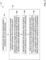
- FIG. 2 is a flow diagram showing an illustrative method 36 for controlling an Air Handling Unit (AHU) (such as the AHU 10) of an HVAC (Heating, Ventilating and Air Conditioning) system servicing a building space (such as the building space 12) of a building.
- the AHU includes a return air duct (such as the return air duct 16) for receiving return air from the building space, a filter (such as the filter 30) for filtering pathogens and other airborne particulates from the return air, a heating and/or cooling unit (such as the heating and/or cooling unit 24) for receiving and condition the return air and providing the conditioned return air as supply air (such as the supply air 28) to the building space.
- the AHU also includes a fan (such as the fan 26) for providing a motive force to move the return air and the supply air through the AHU.
- the illustrative method 36 includes determining when there is an elevated pathogen transmission risk in the building space, as indicated at block 38.
- the AHU is controlled to adjust one or more parameters of the supply air of the AHU to increase a volume of supply air that is required to satisfy a heating and/or cooling call of the building space, as indicated at block 40.
- the AHU may operate the fan and the heating and/or cooling unit of the AHU to provide supply air to the building space that causes a temperature of the air in the building space to move toward the temperature setpoint of the building space.
- controlling the AHU to adjust one or more parameters of the supply air to increase the volume of supply air that is required to satisfy a heating and/or cooling call of the building space may include controlling the heating and/or cooling unit of the AHU to adjust a supply air temperature (e.g. supply air temperature setpoint) of the supply air toward the temperature setpoint of the building space.
- controlling the AHU to adjust one or more parameters of the supply air to increase the volume of supply air that is required to satisfy a heating and/or cooling call of the building space may include controlling the fan of the AHU to increase a flow rate (e.g. duct pressure) of the supply air into the building space, which may enable a larger adjustment in the supply air temperature (e.g.
- the method 36 may include closing the fresh air intake damper to a minimum damper position in response to determining that there is an elevated pathogen transmission risk in the building space. This may increase the air flow through the filter, which in some cases may be considered a clean air flow of substantially pathogen free air into the building space 12.
- FIG. 3 is a flow diagram showing an illustrative method 42 for controlling an Air Handling Unit (AHU) (such as the AHU 10) of an HVAC (Heating, Ventilating and Air Conditioning) system servicing a building space (such as the building space 12) of a building.
- AHU Air Handling Unit
- HVAC Heating, Ventilating and Air Conditioning
- the AHU includes a return air duct (such as the return air duct 16) for receiving return air from the building space, a filter (such as the filter 30) for filtering pathogens and other particulates from the return air, a heating and/or cooling unit (such as the heating and/or cooling unit 24) for receiving and condition the return air and providing the conditioned return air as supply air (such as the supply air 28) to the building space, and a fan (such as the fan 26) for providing a motive force to move the return air and the supply air through the AHU.
- a return air duct such as the return air duct 16
- a filter such as the filter 30
- pathogens and other particulates from the return air
- a heating and/or cooling unit such as the heating and/or cooling unit 24
- a fan such as the fan 26
- the illustrative method 42 includes determining when there is an elevated pathogen transmission risk in the building space, as indicated at block 44. In response to determining that there is an elevated pathogen transmission risk in the building space, the method 42 includes several determinations, as indicated at block 46. The illustrative method 42 includes determining an air change rate for the building space that is estimated to be sufficient to reduce the elevated pathogen transmission risk below a threshold pathogen transmission risk level, as indicated at block 46a. The method 42 includes determining whether the volume of supply air meets the determined air change rate of the building space, as indicated at block 46b.
- the method 42 includes adjusting one or more parameters of the supply air of the AHU to increase the volume of supply air that is required to satisfy the heating and/or cooling call of the building space, as indicated at block 46c.
- controlling the AHU to adjust one or more parameters of the supply air to increase the volume of supply air that is required to satisfy a heating and/or cooling call of the building space may include controlling the heating and/or cooling unit of the AHU to adjust a supply air temperature (e.g. supply air temperature setpoint) of the supply air toward the temperature setpoint of the building space.
- a supply air temperature e.g. supply air temperature setpoint
- the method 42 may include adjusting the fan of the AHU to increase a flow rate of the supply air into the building space.
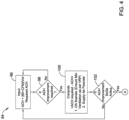
- Figure 4 is a flow diagram showing part of a sequence of operations for controlling ACH (Air Changes per Hour) 94.
- the sequence of operations 94 begins at block 96, where a required ACH value is proposed.
- decision block 98 a determination is made as to whether an ACH improvement is required. If not, control reverts to block 96. If so, control passes to block 100 where flow rates are calculated.
- decision block 102 a determination is made as to whether the ACH Improvement SoOs (Sequence of Operations) are active. If not, control reverts to block 96. If so, control passes to a point A, which is continued on Figure 5 .
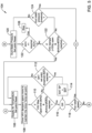
- FIG. 5 shows a sequence of operations 104.
- the sequence of operations 104 begins at block 106, which involves a Supply Air Temperature (SAT) setpoint reset. That is, the supply air temperature (SAT) setpoint of the supply air is adjusted, here called reset, toward the temperature setpoint of the building space.
- SAT Supply Air Temperature
- the zone VAV dampers open further in order to maintain a zone temperature setpoint for the building space. This increases the volume of supply air that is required to satisfy the call for heating and/or cooling.
- decision block 110 a determination is made whether a VAV max open limit has been reached and whether a number of open VAVs threshold has ben reached. If not, control passes to decision block 112, where a determination is made as to whether a SAT setpoint threshold has been reached.
- control reverts to block 106. If the SAT setpoint threshold has not been reached, control passes to block 114 where the SAT setpoint is set equal to the SAT setpoint threshold. From there, control passes to OR block 116. With reference to decision block 110, if the answer is yes, control passes to the OR block 116. Control then passes to a decision block 118, where a determination is made regarding fan speed. If not, control passes to a point B. Otherwise, control passes to a point C, which is continued on Figure 6 .
- Figure 6 shows a sequence of operations 128.
- Control begins at decision block 130, where a determination is made whether the outside air damper is less than fully open. If so, control passes to block 132, where the outside air flowrate setpoint is increased (reset). Otherwise, control passes to a stop block 136. Decision block 134 involves a determination as to whether the ACH exceeds the required ACH. If so, control passes to the stop block 136. Otherwise, control reverts to the decision block 130.
- Figure 7 is a flow diagram showing part of a sequence of operations 138 for PTR (Pathogen Transmission Risk) mitigation.
- the sequence of operations 138 begins with setting an input, as indicated at block 140.
- decision block 142 a determination is made as to whether PTR mitigation is required. If not, control reverts to block 140. If so, control passes to block 144, which involves computing several parameters.
- decision block 146 a determination is made as to whether the PTR Mitigation SoOs are active. If not, control reverts to block 140. IF so, control passes to a point A, which continues on Figure 8 .
- Figure 8 is a flow diagram showing part of a sequence of operations 148 for PTR (Pathogen Transmission Risk) mitigation.
- the sequence of operations 148 begins at block 150, where the Supply Air Temperature setpoint is adjusted (reset).
- Control passes to block 152, where the zone VAV dampers open more fully in order to maintain temperature within the zone.
- decision block 154 a determination is made whether the VAV max open limit and # of open VAVs have been reached. If not, control passes to a decision block 156, where a determination is made as to whether the SAT setpoint threshold has been reached. If not, control reverts to block 150. If so, control passes to block 158, where the SAT setpoint is set equal to the SAT threshold. Control then passes to an OR block 160.
- Control passes to decision block 166, where a determination is made as to whether the PTR is below the PTR safety limit. If so, control passes to an OR block 168 and from there back to the point C. If not, control passes to decision block 172, where a determination is made as to whether the VAV damper is less than 75 percent open. If not, control passes to decision block 172, where a determination is made as to whether the duct static pressure threshold has been reached. If no, control reverts to block 164. Otherwise control reverts to the OR block 168.
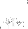
- Figure 9 is a flow diagram showing part of a sequence of operations 174 for PTR (Pathogen Transmission Risk) mitigation.
- the sequence of operations 174 begins from the point C, and continues to decision block 176, where a determination is made whether the outside air damper is less than fully open. Control passes to block 178, where the outside air flowrate setpoint is increased (reset). At decision block 180, a determination is made as to whether the PTR is less than the PTR safety limit. If so, control passes to STOP block 182. Otherwise, control reverts to the decision block 176.
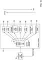
- FIG 10 is a schematic diagram showing an illustrative Sequence of Operations (SoOs) for multiple control objectives for controlling an AHU of an HVAC system.
- Figure 10 shows a division between onsite controls 74 and cloud-based services 76.
- data from the site flows from the onsite controls 74 to the cloud-based services 76.
- the onsite controls 74 includes an operator manual override selector 78.
- IAQ SoOs 80 provide explicit control for IAQ parameters including control loops for CO 2 (carbon dioxide), PM 2.5 (particulate matter) and TVOCs (total volatile organic compounds).
- CO2 SoOs 82 include a CO 2 control loop that is configured to keep return air and space CO 2 concentrations below a CO 2 set point or threshold.
- PTR SoOs 84 provide controls through a PTR control loop for controlling pathogen transmission risk using a PTR model as a soft sensor, and also provide a correlation between PTR and IAQ parameters (with IAQ control dominating PTR control). In some instances, this requires ACH improvement as described herein.
- Default SoOs 86 include existing SoOs that include a variety of control loops that are configured to accomplish a variety of objectives.
- DCV SoOs 88 include control sequences that accomplish a suitable tradeoff between CO 2 and energy objectives.
- Energy Min. SoOs 90 includes control sequences that minimize energy consumption by minimizing ventilation, which may in some situations compromise one or more IAQ parameters.
- Economizer SoOs 92 have an objective to freely cool and heat a space when available.
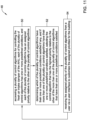
- FIG 11 is a flow diagram showing an illustrative method 48 for controlling an Air Handling Unit (AHU) (such as the AHU 10) of an HVAC (Heating, Ventilating and Air Conditioning) system servicing a building space (such as the building space 12) of a building.
- AHU Air Handling Unit
- HVAC Heating, Ventilating and Air Conditioning
- the AHU includes a return air duct (such as the return air duct 16) for receiving return air from the building space, a filter (such as the filter 30) for filtering pathogens from the return air, a heating and/or cooling unit (such as the heating and/or cooling unit 24) for receiving and condition the return air and providing the conditioned return air as supply air (such as the supply air 28) to the building space, and a fan (such as the fan 26) for providing a motive force to move the return air and the supply air through the AHU.
- a return air duct such as the return air duct 16
- a filter such as the filter 30
- a heating and/or cooling unit such as the heating and/or cooling unit 24
- a fan such as the fan 26
- the illustrative method 48 includes accessing a plurality of control algorithms for controlling the fresh air intake damper of the AHU.
- Each of the plurality of control algorithms includes one or more predefined conditions, and each of the plurality of control algorithms include an assigned priority relative to the other of the plurality of control algorithms, as indicated at block 50.
- a determination is made as to which of the plurality of control algorithms have their one or more predefined conditions satisfied if any. If only one of the plurality of control algorithms has its one or more predefined conditions currently satisfied, the controller is configured to select that control algorithm.
- the method includes selecting the control algorithm that has the highest priority relative to the other of the more than one of the plurality of control algorithms that have their one or more predefined conditions satisfied, as indicated at block 52.
- the fresh air intake damper of the AHU is controlled using the selected control algorithm, as indicated at block 54.
- the method 48 may repeatedly determine which algorithm is appropriate and may utilize that algorithm, thereby autonomously switching between the control algorithms based on current conditions and the assigned control algorithm priorities.
- the accessing, determining, controlling and repeating steps may be executed on premises (e.g. in onsite controls 74 of Figure 10 ).
- the plurality of control algorithms may include an indoor air quality parameter control algorithm that is configured to keep one or more indoor air quality parameters in the building space below one or more indoor air quality thresholds (e.g. IAQ SoOs 80 of Figure 10 ).
- the plurality of control algorithms may include a pathogen transmission risk control algorithm that is configured to keep a pathogen transmission risk in the building space below a pathogen transmission risk threshold (e.g. PTR SoOs 84 of Figure 10 ).
- the plurality of control algorithms may include a demand control ventilation control algorithm that is configured to maintain a balance between one or more indoor air quality parameters and energy consumption of the AHU (e.g. DCV SoOs 88 of Figure 10 ).
- the plurality of control algorithms may include an energy minimization control algorithm that is configured to minimize energy consumption of the AHU by controlling the fresh air intake damper at a minimum ventilation position (e.g. Energy Min SoOs 90 of Figure 10 ).
- the plurality of control algorithms may include an economizer control algorithm that is configured to control the fresh air intake damper to achieve free heating and/or cooling when available (e.g. Economizer SoOs 92 of Figure 10 ).
- one of the one or more predefined conditions of at least one of the plurality of control algorithms may include having a particular sensor available to the AHU. In some instances, one of the one or more predefined conditions of at least one of the plurality of control algorithms may include having one or more sensed values meet one or more predefined conditions. In some instances, one of the one or more predefined conditions of at least one of the plurality of control algorithms may include Boolean logic. In some instances, the method 48 may further include receiving the assigned priority of the plurality of control algorithms from a user via a user interface to customize the assigned priorities for the particular building or building space (zone). In some instances, the one or more predefined conditions of the plurality of control algorithms may not be available to be customized for the building via the user interface.
- Figure 12 is a flow diagram showing an IAQ (Indoor Air Quality) sequence of operations 184, including predefined conditions associated with the IAQ control algorithm.
- the sequence of operations 184 includes evaluating whether the predefined conditions associated with the IAQ control algorithm are currently satisfied.
- the sequence of operations 184 begins at block 186, where several current IAQ parameter values and corresponding IAQ setpoints are received.
- Control passes to decision block 188, where a determination is made as to whether the current CO 2 concentration is less than the CO 2 setpoint. If not, control passes to an OR block 190. Otherwise, control passes to decision block 192, where a determination is made as to whether the VOC (or TVOC) concentration is below the VOC (or TVOC) concentration set point. If not, control passes to the OR block 190.
- the IAQ control algorithm is assigned a priority relative to the other of the plurality of control algorithms. If the IAQ control algorithm is the only one of the plurality of control algorithms that has its one or more predefined conditions currently satisfied, the IAQ control algorithm is activated and the damper controls are operated as indicated at block 198 in order to modulate outside air, return air and exhaust air in accordance with the IAQ control algorithm.
- the outside air may be seen at 200
- the return air may be seen at 202
- the exhaust air may be seen at 204.
- Figure 13 is a flow diagram showing a DCV (Demand-Controlled Ventilation) sequence of operations 208, including predefined conditions associated with the DVC control algorithm.
- the sequence of operations 184 includes evaluating whether the predefined conditions associated with the DVC control algorithm are currently satisfied.
- the sequence of operations 208 begins at block 210, where a return air CO 2 concentration value is received, where control passes to decision blocks 212 and 214.
- decision block 212 a determination is made as whether the return air CO 2 concentration remains above a CO 2 threshold for a period of time
- decision block 214 a determination is made as whether the return air CO 2 concentration remains below the CO 2 threshold for a period of time.
- the DVC control algorithm is assigned a priority relative to the other of the plurality of control algorithms. If the DVC control algorithm is the only one of the plurality of control algorithms that has its one or more predefined conditions currently satisfied, the DVC control algorithm is activated and the damper controls are operated as indicated at blocks 230 and 198 in order to modulate outside air, return air and exhaust air in accordance with the DVC control algorithm.
- the outside air may be seen at 200
- the return air may be seen at 202
- the exhaust air may be seen at 204.
- Figure 14 is a flow diagram showing a PTR (Pathogen Transmission Risk) mitigation/ACH (Air Changes per Hour) improvement sequence of operations 232, including predefined conditions associated with the PTR control algorithm.
- the sequence of operations 232 includes evaluating whether the predefined conditions associated with the PTR control algorithm are currently satisfied.
- the sequence of operations 232 begins at block 236, with receiving a PTR value.
- Control passes to a decision block 236 where a determination is made as to whether the return air CO 2 concentration has remained above a PTR threshold for a period of time. If so, control passes to block 238, indicating that the SoOs for PTR mitigation are active, and then to block 240, where the SoOs provide a new recommended ACH. From there, control passes to an OR block 242.
- the PTR control algorithm is assigned a priority relative to the other of the plurality of control algorithms. If the PTR control algorithm is the only one of the plurality of control algorithms that has its one or more predefined conditions currently satisfied, the PTR control algorithm is activated and the damper controls and fan controls are operated as indicated at blocks 250, 258, 248 and 254, respectively, in order to modulate outside air, return air and exhaust air in accordance with the PTR control algorithm.
- the outside air may be seen at 200
- the return air may be seen at 202
- the exhaust air may be seen at 204.
- Figure 15 is a flow diagram showing an economizer sequence of operations 260, including predefined conditions associated with the economizer control algorithm.
- the sequence of operations 260 begins with an outside air temperature and an RT (room temperature) value being provided to a block 262.
- the block 262 evaluates whether the predefined conditions associated with the economizer control algorithm are currently satisfied.
- the predefined conditions include: If ⁇ OAT ⁇ Preset Temperature OR OAT ⁇ RAT+ 2(configurable) OR OAH ⁇ RH+ 2(configurable) OR OA Enthalpy ⁇ Preset Enthalpy (Single point Enthalpy Changeover) OR OA Enthalpy ⁇ RA Enthalpy (Differential Enthalpy Changeover), It will be appreciated that enthalpy includes dry bulb temperature and humidity. In some instances, depending for example on region and AHU configuration, one of the OR conditions may be used to program the economizer logic operation.
- the economizer control algorithm is assigned a priority relative to the other of the plurality of control algorithms. If the economizer control algorithm is the only one of the plurality of control algorithms that has its one or more predefined conditions currently satisfied, the economizer control algorithm is activated and the damper controls are operated as indicated at block 264 in order to modulate outside air, return air and exhaust air in accordance with the economizer control algorithm.
- the outside air may be seen at 200
- the return air may be seen at 202
- the exhaust air may be seen at 204.
- Figure 16 is a flow diagram showing a CO 2 (Carbon Dioxide) sequence of operations 266, including predefined conditions associated with the CO 2 control algorithm.
- the sequence of operations 266 begins with space CO 2 concentrations and a CO 2 setpoint concentration being provided to a block 268.
- the block 268 evaluates whether the predefined conditions associated with the CO 2 control algorithm are currently satisfied.
- FIG 17 is a schematic diagram showing a PTR (Pathogen Transmission Risk) model 272.
- inputs to the PTR model 272 includes a variety of parameters such as filter efficiency and breathing rates, estimated occupancy, measured supply air humidity, measured AHU air flow rate and measured outside air intake fraction.
- Outputs of the PTR model 272 may include an expected number of transmissions (known as R 0 ) and a total clean air delivery rate. Assumptions made by the PTR model 272 include well mixed air, that infection occurs whenever a predetermined infectious dose is inhaled, and is only valid for transmission through air.
- the expected number of transmissions (R 0 ) represents the indoor reproduction rate. When R 0 is less than 1, infection chances are low. When R 0 is equal to or greater than 1, an infected individual can infect R 0 susceptible occupants.
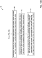
- FIGS 18A and 18B are flow diagrams that together show an illustrative method 56 for controlling an Air Handling Unit (AHU) (such as the AHU 10) of an HVAC (Heating, Ventilating and Air Conditioning) system servicing a building space (such as the building space 12) of a building.
- AHU Air Handling Unit
- HVAC Heating, Ventilating and Air Conditioning
- the illustrative AHU including a return air duct (such as the return duct 16) for receiving return air from the building space, a filter (such as the filter 30) for filtering pathogens from the return air, a heating and/or cooling unit (such as the heating and/or cooling unit 24) for receiving and condition the return air and providing the conditioned return air to the building space as supply air, and a fan (such as the fan 26) for providing a motive force to move the return air and the supply air through the AHU.
- a return air duct such as the return duct 16
- a filter such as the filter 30
- a heating and/or cooling unit such as the heating and/or cooling unit 24
- a fan such as the fan 26
- the method 56 includes determining a pathogen transmission risk function (e.g. R 0 ) that monotonically increases over time and is dependent on a pathogen transmission risk in the building space.
- the pathogen transmission risk function is based at least in part on an occupancy of the building space, a pulmonary ventilation rate, a quanta generation rate and a clean air flow rate of substantially pathogen free air into the building space, as indicated at block 58.
- the method 56 includes determining an ideal monotonically increasing pathogen transmission risk curve extending from an occupied start time to an occupied end time of the building space, as indicated at block 60.
- the pathogen transmission risk function is tracked against the ideal monotonically increasing pathogen transmission risk curve, as indicated at block 62.
- a determination is made as to when the pathogen transmission risk function begins to exceed the ideal monotonically increasing pathogen transmission risk curve for at least a period of time, as indicated at block 64.
- the AHU is controlled to increase the clean air flow rate ( Fclean ) of the substantially pathogen free air into the building space, as indicated at block 66.
- the method 56 may further include projecting a value of the pathogen transmission risk function at the occupied end time, resulting in a projected pathogen transmission risk value, as indicated at block 68.
- a determination is made as to when the projected pathogen transmission risk value is projected to exceed the ideal monotonically increasing pathogen transmission risk curve at the occupied end time by at least a warning amount, as indicated at block 70.
- a warning alert may be issued to a user via a user interface, as indicated at block 72.
- determining the pathogen transmission risk function, determining the ideal monotonically increasing pathogen transmission risk curve, tracking the pathogen transmission risk function, determining when the pathogen transmission risk function exceeds the ideal monotonically increasing pathogen transmission risk curve, and controlling the AHU to increase the clean air flow rate of substantially pathogen free air into the building space may all be executed on premises (e.g. in onsite controls 74 of Figure 10 ).
- the AHU may be controlled in accordance with a programmable schedule that includes occupied time periods and unoccupied time periods, wherein the occupied start time and the occupied end time correspond to one of the occupied time periods of the programmable schedule.
- FIG 19 is a schematic diagram showing an ACH (Air Changes per Hour) recommendation logic 274.
- the logic 274 includes a PTR monitoring model 276.
- Inputs to the PTR monitoring model 276 includes estimated occupancy, measured supply flow rate and measured outside air flowrate.
- One output of the PTR monitoring model 276 includes the expected number of transmissions R 0 , as described above, and a present clean air flowrate, which are both received by an ACH Recommendation Logic block 278.
- the ACH Recommendation Logic block 278 determines a clean air flowrate for the pathogen transmission risk function R 0 to match an ideal monotonically increasing pathogen transmission risk curve.
- the ACH Recommendation Logic block 278 may output an air flowrate recommended to keep the pathogen transmission risk function R 0 within a safe level, as indicated at block 280.
- Figure 20 includes a graph 282 showing an ideal monotonically increasing pathogen transmission risk curve 284, a pathogen transmission risk function R 0 288 if no additional clean air flow is provided, and the expected pathogen transmission risk function R 0 288 if recommendations 280 are followed.
- Figure 21 is a graphical presentation of an early warning logic 290.
- a line 292 an ideal monotonically increasing pathogen transmission risk curve extending from an occupancy start time to an occupancy end time, and represents an R 0 value over time that remains within a safe limit.
- a line segment 294 extends from a previous R 0 value 294a to a present an R 0 value 294b. Extrapolating the line segment 294 into a line 296 indicates that without any changes to ventilation, the R 0 is projected to exceed a predefined threshold (warning amount). In this case, an early warning and/or alert that something needs to be changed may be issued.
- Figure 22 is a flow diagram showing an early warning logic 300.
- the early warning logic 300 beings at an initialization block 302.
- a present value for R 0 is determined at block 304.
- decision block 306 a determination is made as to whether R 0 exceeds a control threshold. If not, control passes to block 308 and R 0 continues to be monitored. If yes, control passes to decision block 310, where a determination is made as to whether the current time is after a starting time and before an ending time. If not, control passes to block 308. If yes, control passes to block 312 where several ideal parameter values are calculated. Control passes to block 314 where a current error is calculated. The present slope is used to predict a final PTR value, as indicated at block 316.
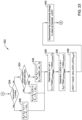
- Figure 23 is a flow diagram showing part of an ACH (Air Changes per Hour) recommendation logic 322.
- the ACH recommendation logic 322 begins at point A, and then passes to a decision block 324, where a determination is made as to whether the current error is larger than an offset (such as 0). If so, control passes to block 326 where several parameters are updated. Control then passes to block 328. If at decision block 324 the answer was no, control passes to decision block 330, where a determination is made as to whether the present slope exceeds a present ideal slope. If yes, control passes to block 332 and several parameters are updated. If not, control passes to block 334 and several parameters are updated. From each of block 332 and 334, control passes to block 328, where the error is calculated.
- an offset such as 0
- Control passes to block 336, where a change in ACH is determined, and then to block 338, where a change in ACH is calculated. From there, control passes to block 340, wherein an incremental change in the clean air flowrate is recommended. Control then passes to point B.
- Figures 24 and 25 provide alternates to what may happen starting from point B.
- an approach 342 begins at block 344 with determining a recommended change in ACH.
- the outside air flowrate may be set based on a site-specific control strategy.
- the required supply air flowrate is calculated.
- Figure 25 shows an approach 350 that begins with determining a recommended change in ACH, as indicated at block 352.
- An optimization problem is formulated, as indicated at block 354.
Landscapes
- Engineering & Computer Science (AREA)
- Chemical & Material Sciences (AREA)
- Combustion & Propulsion (AREA)
- Mechanical Engineering (AREA)
- General Engineering & Computer Science (AREA)
- Signal Processing (AREA)
- Physics & Mathematics (AREA)
- Fuzzy Systems (AREA)
- Mathematical Physics (AREA)
- Fluid Mechanics (AREA)
- Air Conditioning Control Device (AREA)
Abstract
Description
- The present disclosure relates to methods and systems for operating a Heating, Ventilating and Air Conditioning (HVAC) system.
- HVAC systems provide conditioned air for heating and cooling the interior of a building. Some HVAC systems also can provide fresh air ventilation into the building while exhausting an equivalent amount of inside air. Such fresh air ventilation is useful in reducing contaminates produced in the building. However, there are often costs involved in conditioning the fresh air before it can be deployed in the building. For example, in the winter, the cold fresh air must typically be heated by the HVAC system, and in some cases, humidity must be added. Likewise, in the summer, the warm fresh air must typically be cooled by the HVAC system, and in some cases, humidity must be removed. Thus, to reduce operating costs, it is often desirable to minimize the ventilation rate while still adequately ventilating the building given the current contaminates or expected contaminates in the building.
- Under some conditions, such as during a pandemic, it may be desirable to prioritize an increased ventilation rate over energy costs to help reduce the spread of pathogens within the building. Under these conditions, if the ventilation rate is set too high, given the current indoor and outdoor conditions, the HVAC system may lack the heating and/or cooling capacity to adequately condition the incoming fresh air while still maintaining occupant comfort in the building. What would be desirable are methods and systems for operating an HVAC system to provide adequate ventilation while minimizing energy usage and maintaining comfort.
- The present disclosure relates to methods and systems for operating a Heating, Ventilating and Air Conditioning (HVAC) system. An example may be found in a method for controlling an Air Handling Unit (AHU), where the AHU includes a return air duct for receiving return air from the building space, a filter for filtering pathogens and/or other airborne contaminates from the return air, a heating and/or cooling unit for receiving and condition the return air and providing the conditioned return air as supply air to the building space. The illustrative AHU includes a fan for providing a motive force to move the return air and the supply air through the AHU. The illustrative method includes determining when the indoor air quality in the building space has fallen below the threshold. In some cases, this may include determining when there is an elevated pathogen transmission risk in the building space. In response to determining that the indoor air quality in the building space has fallen below the threshold (e.g. there is an elevated pathogen transmission risk in the building space), controlling the AHU to adjust one or more parameters of the supply air of the AHU to increase a volume of supply air that must be provided by the AHU to satisfy a heating and/or cooling call of the building space. Adjusting one or more parameters of the supply air of the AHU to increase a volume of supply air that must be provided by the AHU to satisfy a heating and/or cooling call of the building space may include, for example, controlling the heating and/or cooling unit of the AHU to adjust a supply air temperature of the supply air toward a temperature setpoint of the building space and/or controlling the fan of the AHU to increase a flow rate of the supply air into the building space. These are just examples.
- Another example may be found in a method for controlling a fresh air intake of an Air Handling Unit (AHU), where the AHU includes a fresh air intake damper for admitting a fresh air ventilation air flow, a return air duct for receiving return air from the building space, and a mixed air duct for mixing the fresh air ventilation air flow from the fresh air intake damper and return air from the return air duct and providing a mixed air flow to a heating and/or cooling unit of the AHU which supplies a supply air flow to the building space. The illustrative AHU includes a fan for providing a motive force to move the return air, the fresh air ventilation air flow, the mixed air flow and the supply air flow through the AHU. The illustrative method includes accessing a plurality of control algorithms for controlling the fresh air intake damper of the AHU. Each of the plurality of control algorithms has one or more predefined conditions. Each of the plurality of control algorithms has an assigned priority relative to the other of the plurality of control algorithms. A determination is made as to which of the plurality of control algorithms currently have their one or more predefined conditions satisfied, if any, and if more than one of the plurality of control algorithms have their one or more predefined conditions satisfied, the control algorithm that has the highest priority relative to the other of the more than one of the plurality of control algorithms that have their one or more predefined conditions satisfied is selected. The fresh air intake damper of the AHU is controlled using the selected control algorithm. The determining and controlling steps are repeated over time, thereby autonomously switching between the control algorithms based on current conditions and the assigned control algorithm priorities.
- Another example may be found in a method for controlling an Air Handling Unit (AHU), wherein the AHU includes a return air duct for receiving return air from the building space, a filter for filtering pathogens from the return air, and a heating and/or cooling unit for receiving and condition the return air and providing the conditioned return air to the building space as supply air. The illustrative AHU includes a fan for providing a motive force to move the return air and the supply air through the AHU. The illustrative method includes determining a pathogen transmission risk function that monotonically increases over time and is dependent on a pathogen transmission risk in the building space. In some instances, the pathogen transmission risk function is based at least in part on an occupancy of the building space, a pulmonary ventilation rate, a quanta generation rate and a clean air flow rate of substantially pathogen free air into the building space. The illustrative method includes determining an ideal monotonically increasing pathogen transmission risk curve extending from an occupied start time to an occupied end time of the building space, and tracking the pathogen transmission risk function against the ideal monotonically increasing pathogen transmission risk curve. The illustrative method includes determining when the pathogen transmission risk function begins to exceed the ideal monotonically increasing pathogen transmission risk curve for at least a period of time. In response to determining that the pathogen transmission risk function exceeds the ideal monotonically increasing pathogen transmission risk curve for at least the period of time, the AHU is controlled to increase the clean air flow rate of substantially pathogen free air into the building space.
- The preceding summary is provided to facilitate an understanding of some of the innovative features unique to the present disclosure and is not intended to be a full description. A full appreciation of the disclosure can be gained by taking the entire specification, claims, figures, and abstract as a whole.
- The disclosure may be more completely understood in consideration of the following description of various examples in connection with the accompanying drawings, in which:
-
Figure 1 is a schematic block diagram showing an illustrative Air Handling Unit (AHU) that forms part of a Heating, Ventilating and Air Conditioning (HVAC) system servicing a building space; -
Figure 2 is a flow diagram showing an illustrative method for controlling an Air Handling Unit (AHU) of an HVAC (Heating, Ventilating and Air Conditioning) system servicing a building space of a building; -
Figure 3 is a flow diagram showing an illustrative method for controlling an Air Handling Unit (AHU) of an HVAC (Heating, Ventilating and Air Conditioning) system servicing a building space of a building; -
Figure 4 is a flow diagram showing part of a sequence of operations for controlling ACH (Air Changes per Hour); -
Figure 5 is a flow diagram showing part of a sequence of operations for controlling ACH (Air Changes per Hour); -
Figure 6 is a flow diagram showing part of a sequence of operations for controlling ACH (Air Changes per Hour); -
Figure 7 is a flow diagram showing part of a sequence of operations for controlling PTR (Pathogen Transmission Risk) mitigation; -
Figure 8 is a flow diagram showing part of a sequence of operations for controlling PTR (Pathogen Transmission Risk) mitigation; -
Figure 9 is a flow diagram showing part of a sequence of operations for controlling PTR (Pathogen Transmission Risk) mitigation; -
Figure 10 is a schematic diagram showing illustrative multiple control objectives for a building space of a building; -
Figure 11 is a flow diagram showing an illustrative method for controlling an Air Handling Unit (AHU) of an HVAC (Heating, Ventilating and Air Conditioning) system servicing a building space of a building; -
Figure 12 is a flow diagram showing an IAQ (Indoor Air Quality) sequence of operations; -
Figure 13 is a flow diagram showing a DCV (Demand-Controlled Ventilation) sequence of operations; -
Figure 14 is a flow diagram showing a PTR (Pathogen Transmission Risk) mitigation/ACH (Air Changes per Hour) improvement sequence of operations; -
Figure 15 is a flow diagram showing an economizer sequence of operations; -
Figure 16 is a flow diagram showing a CO2 (Carbon Dioxide) sequence of operations; -
Figure 17 is a schematic diagram showing a PTR (Pathogen Transmission Risk) model; -
Figures 18A and18B are flow diagrams that together show an illustrative method for controlling an Air Handling Unit (AHU) of an HVAC (Heating, Ventilating and Air Conditioning) system servicing a building space of a building; -
Figure 19 is a schematic diagram showing an ACH (Air Changes per Hour) recommendation logic; -
Figure 20 is a graphical representation of illustrative data accompanyingFigure 19 ; -
Figure 21 is a graphical presentation of an early warning logic; -
Figure 22 is a flow diagram showing an early warning logic; -
Figure 23 is a flow diagram showing an ACH (Air Changes per Hour) recommendation logic; -
Figure 24 is a flow diagram showing an illustrative method; and -
Figure 25 is a flow diagram showing an illustrative method. - While the disclosure is amenable to various modifications and alternative forms, specifics thereof have been shown by way of example in the drawings and will be described in detail. It should be understood, however, that the intention is not to limit the disclosure to the particular examples described. On the contrary, the intention is to cover all modifications, equivalents, and alternatives falling within the spirit and scope of the disclosure.
- The following description should be read with reference to the drawings, in which like elements in different drawings are numbered in like fashion. The drawings, which are not necessarily to scale, depict examples that are not intended to limit the scope of the disclosure. Although examples are illustrated for the various elements, those skilled in the art will recognize that many of the examples provided have suitable alternatives that may be utilized.
- All numbers are herein assumed to be modified by the term "about", unless the content clearly dictates otherwise. The recitation of numerical ranges by endpoints includes all numbers subsumed within that range (e.g., 1 to 5 includes 1, 1.5, 2, 2.75, 3, 3.80, 4, and 5).
- As used in this specification and the appended claims, the singular forms "a", "an", and "the" include the plural referents unless the content clearly dictates otherwise. As used in this specification and the appended claims, the term "or" is generally employed in its sense including "and/or" unless the content clearly dictates otherwise.
- It is noted that references in the specification to "an embodiment", "some embodiments", "other embodiments", etc., indicate that the embodiment described may include a particular feature, structure, or characteristic, but every embodiment may not necessarily include the particular feature, structure, or characteristic. Moreover, such phrases are not necessarily referring to the same embodiment. Further, when a particular feature, structure, or characteristic is described in connection with an embodiment, it is contemplated that the feature, structure, or characteristic is described in connection with an embodiment, it is contemplated that the feature, structure, or characteristic may be applied to other embodiments whether or not explicitly described unless clearly stated to the contrary.
-
Figure 1 is a schematic block diagram showing an illustrative Air Handling Unit (AHU) 10 that may form part of a Heating, Ventilating and Air Conditioning (HVAC) system servicing abuilding space 12. Thebuilding space 12 may represent an entire building, for example, or a single floor or zone within a building. TheAHU 10 includes a freshair intake damper 14 for admitting a fresh air ventilation flow from outside of the building. TheAHU 10 includes areturn air duct 16 for receiving return air from thebuilding space 12. TheAHU 10 includes amixed air duct 18 for mixing a fresh airventilation air flow 20 from the freshair intake damper 14 and return air from thereturn air duct 16 and provides amixed air flow 22. Themixed air flow 22 flows to a heating and/orcooling unit 24. - In some instances, as shown, a
fan 26 may be disposed between themixed air duct 18 and the heating and/orcooling unit 24. In some instances, the heating and/orcooling unit 24 may be disposed between themixed air duct 18 and thefan 26. In either case, thefan 26 provides a motive force to move the return air within thereturn air duct 16 and the fresh airventilation air flow 20. In some instances, thefan 26 also provides a motive force to move thesupply air flow 28. In some instances, thefan 26 also provides a motive force to move themixed air flow 22. The heated or cooled air exiting the heating and/orcooling unit 24 represents asupply air flow 28. In some instances, theAHU 10 may include onefan 26, or may include two ormore fans 26 that may be distributed within theAHU 10. TheAHU 10 includes afilter 30. Thefilter 30 may filter the air from the building space before it is returned to themixed air duct 18. In some cases, thefilter 30 may be effective for filtering some pathogens and/or other airborne contaminates from thereturn air 16. - The
illustrative AHU 10 includes acontrol valve 32 that is configured to control the flow of a heating or cooling fluid into the heating and/orcooling unit 24, including aninlet flow 32a and anoutlet flow 32b. TheAHU 10 has a load capacity that provides an indication of a maximum amount of heat that theAHU 10 is able to transfer between a heating or cooling fluid and air being blown through theAHU 10. - A
controller 34 is operatively coupled to the freshair intake damper 14, the heating and/orcooling unit 24 and thefan 26. During a heating or cooling call, thecontroller 34 may be configured to operate thefan 26 and the heating and/orcooling unit 24 in order to provide conditionedsupply air 28 to thebuilding space 12 that causes the temperature of the air in thebuilding space 12 to move towards a temperature setpoint. In a heating mode, this may include heating thesupply air 28 and providing theheated supply air 28 to thebuilding space 12, thereby causing the temperature of the air in thebuilding space 12 to rise to a heating temperature setpoint of thebuilding space 12. In a cooling mode, this may include cooling thesupply air 28 and providing the cooledsupply air 28 to thebuilding space 12, thereby causing the temperature of the air in thebuilding space 12 to drop to a cooling temperature setpoint of thebuilding space 12. Typically, the heating and/orcooling unit 24 of theAHU 10 is controlled to heat or cool thesupply air 28 to a heating or cooling supply air temperature setpoint, and operate the fan at a set fan speed, causing theAHU 10 to produce a supply air stream that is at the heating or cooling supply air temperature setpoint and at a set flow rate (e.g. a set duct pressure). The AHU then remains in this state until the temperature of the air in thebuilding space 12 reaches the temperature setpoint of thebuilding space 12. This cycle is repeated each time the temperature of the air in thebuilding space 12 drifts away from the temperature setpoint of thebuilding space 12, sometimes by at least a dead band amount. - In some cases, the
controller 34 is configured to determine when the indoor air quality in the building space has fallen below the threshold. In some cases, this includes determining when there is an elevated pathogen transmission risk in thebuilding space 12. In response, thecontroller 34 may control theAHU 10 to adjust one or more parameters (e.g. supply air temperature setpoint of the supply air and/or duct pressure of the supply air) of thesupply air 28 of theAHU 10 in order to increase the volume ofsupply air 28 that is required to satisfy the heating and/or cooling call of thebuilding space 12. In some cases, this cause an increased volume ofreturn air 16 from thebuilding space 12 to be passes through thefilter 30 and returned to the building space by theAHU 10. This may increase the indoor air quality in the building space 12 (e.g. reduce the pathogen concentration in thebuilding space 12 and thus reduce the pathogen transmission risk). Because filtered air may be more effective at increasing the indoor air quality (e.g. reducing the pathogen transmission risk in the building space 12) than admitting additional fresh ventilation air into thebuilding space 12 via the freshair intake damper 14, in some cases the freshair intake damper 14 may be set to a minimum ventilation setting when the one or more parameters (e.g. supply air temperature setpoint of the supply air and/or duct pressure of the supply air) of thesupply air 28 of theAHU 10 are adjusted. - As indicated above, in some cases, the
controller 34 may be configured to control operation of the heating and/orcooling unit 24 of theAHU 10 to adjust a supply air temperature (e.g. the supply air temperature setpoint) of thesupply air 28 toward the temperature setpoint of thebuilding space 12. In some instances, thecontroller 34 may be configured to control operation of thefan 26 to increase a flow rate of the supply air into the building space 12 (and increase the duct pressure of the supply air 28), which can enable a larger adjustment to the supply air temperature (e.g. the supply air temperature setpoint) toward the temperature setpoint of thebuilding space 12 while still being able to satisfy the heating and/or cooling call. - In some instances, when the
controller 34 determines that there is an elevated pathogen transmission risk in thebuilding space 12, thecontroller 34 may determine a desired air change rate for thebuilding space 12 that is estimated to be sufficient to reduce the elevated pathogen transmission risk below a threshold pathogen transmission risk level. Thecontroller 24 may adjust one or more first parameters (e.g. supply air temperature setpoint of the supply air) of thesupply air 28 of theAHU 10 in order to increase the volume ofsupply air 28 that is required to satisfy the heating and/or cooling call of thebuilding space 12. Thecontroller 24 may then determine whether the increased volume of supply air meets the determined air change rate for thebuilding space 12. When the volume of the supply air does not meet the determined air change rate for thebuilding space 12, thecontroller 34 is configured to adjust one or more second parameters (e.g. duct pressure) of thesupply air 28 of theAHU 10 to further increase the volume ofsupply air 28 that is required to satisfy the heating and/or cooling call of thebuilding space 12. - More particularly, and in some instances, when the
controller 34 adjusts the supply air temperature setpoint of thesupply air 28 of theAHU 10 to such a degree that theAHU 10 can no longer satisfy the heating and/or cooling call, but the volume of thesupply air 28 still does not meet the determined air change rate for thebuilding space 12, thecontroller 34 may be configured to adjust thefan 26 of theAHU 10 to increase a flow rate of thesupply air 28 into thebuilding space 12. This may allow theAHU 10 to satisfy the heating and/or cooling call even with the reduced air temperature setpoint of thesupply air 28. As indicated above, and in some cases, thecontroller 34 may be configured to close the freshair intake damper 14 to a minimum damper position in response to determining that there is an elevated pathogen transmission risk in thebuilding space 12. This may increase the air flow through thefilter 30, which in some cases may be considered a clean air flow of substantially pathogen free air into thebuilding space 12. - As further described herein such as with respect to
Figures 10-16 , in some instances, thecontroller 34 may be configured to access a plurality of control algorithms for controlling the freshair intake damper 14 of theAHU 10, each of the plurality of control algorithms having one or more predefined conditions, and each of the plurality of control algorithms having an assigned priority relative to the other of the plurality of control algorithms. Thecontroller 34 may be configured to determine which of the plurality of control algorithms have their one or more predefined conditions currently satisfied, if any. If only one of the plurality of control algorithms has its one or more predefined conditions currently satisfied, the controller is configured to select that control algorithm. However, if more than one of the plurality of control algorithms have their one or more predefined conditions satisfied, thecontroller 34 may be configured to select the control algorithm that has the highest priority relative to the other of the more than one of the plurality of control algorithms that have their one or more predefined conditions satisfied. In some instances, thecontroller 34 may control the freshair intake damper 14 of theAHU 10 using the selected control algorithm. In some instances, thecontroller 34 may repeatedly determine which algorithm is appropriate and may utilize that algorithm, thereby autonomously switching between the control algorithms based on current conditions and the assigned control algorithm priorities. - In some instances, the plurality of control algorithms include an indoor air quality parameter control algorithm that is configured to keep one or more indoor air quality parameters in the
building space 12 below one or more indoor air quality thresholds (e.g. CO2, PM2.5, TVOC). In some instances, the plurality of control algorithms include a pathogen transmission risk control algorithm that is configured to keep a pathogen transmission risk in thebuilding space 12 below a pathogen transmission risk threshold. In some instances, the plurality of control algorithms include a demand control ventilation control algorithm that is configured to maintain a balance between one or more indoor air quality parameters and energy consumption of theAHU 10. In some instances, the plurality of control algorithms include an energy minimization control algorithm that is configured to minimize energy consumption of theAHU 10 by controlling the freshair intake damper 14 at a minimum ventilation position. In some instances, the plurality of control algorithms include an economizer control algorithm that is configured to control the freshair intake damper 14 to achieve free heating and/or cooling when available. - In some instances, one of the one or more predefined conditions of at least one of the plurality of control algorithms may include having a particular sensor available to the
AHU 10. In some instances, one of the one or more predefined conditions of at least one of the plurality of control algorithms include having one or more sensed values meet one or more predefined conditions. In some instances, one of the one or more predefined conditions may include Boolean logic. In some cases, thecontroller 34 may be configured to receive the assigned priority of the plurality of control algorithms from a user via a user interface to customize the assigned priorities for the building and/orbuilding space 12. In some instances, the one or more predefined conditions of the plurality of control algorithms are not available to be customized for the building via the user interface. - As further described herein such as with respect to
Figures 17-25 , in some instances, thecontroller 34 may be configured to determine a pathogen transmission risk function that monotonically increases over time and is dependent on a pathogen transmission risk in thebuilding space 12. In some instances, the pathogen transmission risk function is based at least in part on an occupancy of thebuilding space 12, a pulmonary ventilation rate, a quanta generation rate and a clean air flow rate of substantially pathogen free air into thebuilding space 12. Thecontroller 34 may be configured to determine an ideal monotonically increasing pathogen transmission risk curve extending from an occupied start time to an occupied end time of thebuilding space 12 and to track the pathogen transmission risk function against the ideal monotonically increasing pathogen transmission risk curve. In some instances, thecontroller 34 may be configured to determine when the pathogen transmission risk function begins to exceed the ideal monotonically increasing pathogen transmission risk curve for at least a period of time and, in response to determining that the pathogen transmission risk function exceeds the ideal monotonically increasing pathogen transmission risk curve for at least the period of time, thecontroller 34 may be configured to control theAHU 10 to increase the clean air flow rate of substantially pathogen free air into thebuilding space 12. - In some instances, the
controller 34 may be configured to project a value of the pathogen transmission risk function at the occupied end time, resulting in a projected pathogen transmission risk value, and to determine when the projected pathogen transmission risk value is projected to exceed the ideal monotonically increasing pathogen transmission risk curve at the occupied end time by at least a warning amount. In response to determining that the projected pathogen transmission risk value is projected to exceed the ideal monotonically increasing pathogen transmission risk curve at the occupied end time by at least the warning amount, thecontroller 34 may be configured to issue a warning alert to a user via a user interface. In some instances, thecontroller 34 may be configured to control theAHU 10 in accordance with a programmable schedule that includes occupied time periods and unoccupied time periods, wherein the occupied start time and the occupied end time correspond to one of the occupied time periods of the programmable schedule. -
Figure 2 is a flow diagram showing anillustrative method 36 for controlling an Air Handling Unit (AHU) (such as the AHU 10) of an HVAC (Heating, Ventilating and Air Conditioning) system servicing a building space (such as the building space 12) of a building. The AHU includes a return air duct (such as the return air duct 16) for receiving return air from the building space, a filter (such as the filter 30) for filtering pathogens and other airborne particulates from the return air, a heating and/or cooling unit (such as the heating and/or cooling unit 24) for receiving and condition the return air and providing the conditioned return air as supply air (such as the supply air 28) to the building space. The AHU also includes a fan (such as the fan 26) for providing a motive force to move the return air and the supply air through the AHU. - The
illustrative method 36 includes determining when there is an elevated pathogen transmission risk in the building space, as indicated atblock 38. In response to determining that there is an elevated pathogen transmission risk in the building space, the AHU is controlled to adjust one or more parameters of the supply air of the AHU to increase a volume of supply air that is required to satisfy a heating and/or cooling call of the building space, as indicated atblock 40. In some instances, in response to the heating and/or cooling call, the AHU may operate the fan and the heating and/or cooling unit of the AHU to provide supply air to the building space that causes a temperature of the air in the building space to move toward the temperature setpoint of the building space. In some instances, controlling the AHU to adjust one or more parameters of the supply air to increase the volume of supply air that is required to satisfy a heating and/or cooling call of the building space may include controlling the heating and/or cooling unit of the AHU to adjust a supply air temperature (e.g. supply air temperature setpoint) of the supply air toward the temperature setpoint of the building space. In some instances, controlling the AHU to adjust one or more parameters of the supply air to increase the volume of supply air that is required to satisfy a heating and/or cooling call of the building space may include controlling the fan of the AHU to increase a flow rate (e.g. duct pressure) of the supply air into the building space, which may enable a larger adjustment in the supply air temperature (e.g. supply air temperature setpoint) toward the temperature setpoint of the building space while still being able to satisfy the heating and/or cooling call. In some instances, themethod 36 may include closing the fresh air intake damper to a minimum damper position in response to determining that there is an elevated pathogen transmission risk in the building space. This may increase the air flow through the filter, which in some cases may be considered a clean air flow of substantially pathogen free air into thebuilding space 12. -
Figure 3 is a flow diagram showing anillustrative method 42 for controlling an Air Handling Unit (AHU) (such as the AHU 10) of an HVAC (Heating, Ventilating and Air Conditioning) system servicing a building space (such as the building space 12) of a building. The AHU includes a return air duct (such as the return air duct 16) for receiving return air from the building space, a filter (such as the filter 30) for filtering pathogens and other particulates from the return air, a heating and/or cooling unit (such as the heating and/or cooling unit 24) for receiving and condition the return air and providing the conditioned return air as supply air (such as the supply air 28) to the building space, and a fan (such as the fan 26) for providing a motive force to move the return air and the supply air through the AHU. - The
illustrative method 42 includes determining when there is an elevated pathogen transmission risk in the building space, as indicated atblock 44. In response to determining that there is an elevated pathogen transmission risk in the building space, themethod 42 includes several determinations, as indicated atblock 46. Theillustrative method 42 includes determining an air change rate for the building space that is estimated to be sufficient to reduce the elevated pathogen transmission risk below a threshold pathogen transmission risk level, as indicated atblock 46a. Themethod 42 includes determining whether the volume of supply air meets the determined air change rate of the building space, as indicated atblock 46b. When the volume of the supply air does not meet the determined air change rate for the building space, themethod 42 includes adjusting one or more parameters of the supply air of the AHU to increase the volume of supply air that is required to satisfy the heating and/or cooling call of the building space, as indicated atblock 46c. - In some instances, controlling the AHU to adjust one or more parameters of the supply air to increase the volume of supply air that is required to satisfy a heating and/or cooling call of the building space may include controlling the heating and/or cooling unit of the AHU to adjust a supply air temperature (e.g. supply air temperature setpoint) of the supply air toward the temperature setpoint of the building space. In some instances, when the supply air temperature of the supply air (e.g. supply air temperature setpoint) is adjusted such that the AHU can no longer satisfy the heating and/or cooling call, and the volume of the supply air still does not meet the determined air change rate for the building space, the
method 42 may include adjusting the fan of the AHU to increase a flow rate of the supply air into the building space. -
Figure 4 is a flow diagram showing part of a sequence of operations for controlling ACH (Air Changes per Hour) 94. The sequence ofoperations 94 begins atblock 96, where a required ACH value is proposed. Atdecision block 98, a determination is made as to whether an ACH improvement is required. If not, control reverts to block 96. If so, control passes to block 100 where flow rates are calculated. Atdecision block 102, a determination is made as to whether the ACH Improvement SoOs (Sequence of Operations) are active. If not, control reverts to block 96. If so, control passes to a point A, which is continued onFigure 5 . -
Figure 5 shows a sequence ofoperations 104. The sequence ofoperations 104 begins atblock 106, which involves a Supply Air Temperature (SAT) setpoint reset. That is, the supply air temperature (SAT) setpoint of the supply air is adjusted, here called reset, toward the temperature setpoint of the building space. Atblock 108, the zone VAV dampers open further in order to maintain a zone temperature setpoint for the building space. This increases the volume of supply air that is required to satisfy the call for heating and/or cooling. Atdecision block 110, a determination is made whether a VAV max open limit has been reached and whether a number of open VAVs threshold has ben reached. If not, control passes to decision block 112, where a determination is made as to whether a SAT setpoint threshold has been reached. If the SAT setpoint threshold has not been reached, control reverts to block 106. If the SAT setpoint threshold has been met, control passes to block 114 where the SAT setpoint is set equal to the SAT setpoint threshold. From there, control passes to OR block 116. With reference to decision block 110, if the answer is yes, control passes to the OR block 116. Control then passes to adecision block 118, where a determination is made regarding fan speed. If not, control passes to a point B. Otherwise, control passes to a point C, which is continued onFigure 6 . - From point B, control passes to a
block 120, where the duct static pressure setpoint is adjusted (reset). Control passes to decision block 122, where a determination is made as to whether the ACH is greater than the required ACH. If yes, control passes to block 116 and the sequence terminates. If not, control passes to decision block 122, where a determination is made whether a VAV max open limit has been reached and whether a number of open VAVs threshold has been reached. If so, control reverts to block 106. Otherwise, control passes to decision block 124, where a determination is made whether a duct static pressure threshold has been reached. If so, control passes to the point C. Otherwise, control passes to block 120. -
Figure 6 shows a sequence ofoperations 128. Control begins atdecision block 130, where a determination is made whether the outside air damper is less than fully open. If so, control passes to block 132, where the outside air flowrate setpoint is increased (reset). Otherwise, control passes to astop block 136.Decision block 134 involves a determination as to whether the ACH exceeds the required ACH. If so, control passes to thestop block 136. Otherwise, control reverts to thedecision block 130. -
Figure 7 is a flow diagram showing part of a sequence ofoperations 138 for PTR (Pathogen Transmission Risk) mitigation. The sequence ofoperations 138 begins with setting an input, as indicated atblock 140. Atdecision block 142, a determination is made as to whether PTR mitigation is required. If not, control reverts to block 140. If so, control passes to block 144, which involves computing several parameters. Atdecision block 146, a determination is made as to whether the PTR Mitigation SoOs are active. If not, control reverts to block 140. IF so, control passes to a point A, which continues onFigure 8 . -
Figure 8 is a flow diagram showing part of a sequence ofoperations 148 for PTR (Pathogen Transmission Risk) mitigation. The sequence ofoperations 148 begins atblock 150, where the Supply Air Temperature setpoint is adjusted (reset). Control passes to block 152, where the zone VAV dampers open more fully in order to maintain temperature within the zone. Atdecision block 154, a determination is made whether the VAV max open limit and # of open VAVs have been reached. If not, control passes to adecision block 156, where a determination is made as to whether the SAT setpoint threshold has been reached. If not, control reverts to block 150. If so, control passes to block 158, where the SAT setpoint is set equal to the SAT threshold. Control then passes to an ORblock 160. If atdecision block 154, a determination is made that the VAV max open limit and # of open VAVs have been reached, control passes to the OR block 160. From the OR block 160, control passes to decision block 118, where a determination is made regarding fan speed. If not, control passes to a point B. Otherwise, control passes to a point C, which is continued onFigure 9 . - From the point B, control passes to a
block 164, where the duct static pressure setpoint is increased (reset) by increasing the fan speed. Control passes to decision block 166, where a determination is made as to whether the PTR is below the PTR safety limit. If so, control passes to an OR block 168 and from there back to the point C. If not, control passes to decision block 172, where a determination is made as to whether the VAV damper is less than 75 percent open. If not, control passes to decision block 172, where a determination is made as to whether the duct static pressure threshold has been reached. If no, control reverts to block 164. Otherwise control reverts to the OR block 168. -
Figure 9 is a flow diagram showing part of a sequence ofoperations 174 for PTR (Pathogen Transmission Risk) mitigation. The sequence ofoperations 174 begins from the point C, and continues to decision block 176, where a determination is made whether the outside air damper is less than fully open. Control passes to block 178, where the outside air flowrate setpoint is increased (reset). Atdecision block 180, a determination is made as to whether the PTR is less than the PTR safety limit. If so, control passes to STOPblock 182. Otherwise, control reverts to thedecision block 176. -
Figure 10 is a schematic diagram showing an illustrative Sequence of Operations (SoOs) for multiple control objectives for controlling an AHU of an HVAC system.Figure 10 shows a division betweenonsite controls 74 and cloud-basedservices 76. In the example shown, data from the site flows from theonsite controls 74 to the cloud-basedservices 76. Theonsite controls 74 includes an operatormanual override selector 78. A number of different SoOs are shown, along with their relative impact on energy consumption and indoor air quality.IAQ SoOs 80 provide explicit control for IAQ parameters including control loops for CO2 (carbon dioxide), PM2.5 (particulate matter) and TVOCs (total volatile organic compounds).CO2 SoOs 82 include a CO2 control loop that is configured to keep return air and space CO2 concentrations below a CO2 set point or threshold.PTR SoOs 84 provide controls through a PTR control loop for controlling pathogen transmission risk using a PTR model as a soft sensor, and also provide a correlation between PTR and IAQ parameters (with IAQ control dominating PTR control). In some instances, this requires ACH improvement as described herein.Default SoOs 86 include existing SoOs that include a variety of control loops that are configured to accomplish a variety of objectives.DCV SoOs 88 include control sequences that accomplish a suitable tradeoff between CO2 and energy objectives. Energy Min.SoOs 90 includes control sequences that minimize energy consumption by minimizing ventilation, which may in some situations compromise one or more IAQ parameters.Economizer SoOs 92 have an objective to freely cool and heat a space when available. -
Figure 11 is a flow diagram showing anillustrative method 48 for controlling an Air Handling Unit (AHU) (such as the AHU 10) of an HVAC (Heating, Ventilating and Air Conditioning) system servicing a building space (such as the building space 12) of a building. The AHU includes a return air duct (such as the return air duct 16) for receiving return air from the building space, a filter (such as the filter 30) for filtering pathogens from the return air, a heating and/or cooling unit (such as the heating and/or cooling unit 24) for receiving and condition the return air and providing the conditioned return air as supply air (such as the supply air 28) to the building space, and a fan (such as the fan 26) for providing a motive force to move the return air and the supply air through the AHU. - The
illustrative method 48 includes accessing a plurality of control algorithms for controlling the fresh air intake damper of the AHU. Each of the plurality of control algorithms includes one or more predefined conditions, and each of the plurality of control algorithms include an assigned priority relative to the other of the plurality of control algorithms, as indicated atblock 50. A determination is made as to which of the plurality of control algorithms have their one or more predefined conditions satisfied if any. If only one of the plurality of control algorithms has its one or more predefined conditions currently satisfied, the controller is configured to select that control algorithm. However, if more than one of the plurality of control algorithms have their one or more predefined conditions satisfied, the method includes selecting the control algorithm that has the highest priority relative to the other of the more than one of the plurality of control algorithms that have their one or more predefined conditions satisfied, as indicated atblock 52. The fresh air intake damper of the AHU is controlled using the selected control algorithm, as indicated atblock 54. In some instances, themethod 48 may repeatedly determine which algorithm is appropriate and may utilize that algorithm, thereby autonomously switching between the control algorithms based on current conditions and the assigned control algorithm priorities. In some instances, the accessing, determining, controlling and repeating steps may be executed on premises (e.g. inonsite controls 74 ofFigure 10 ). - In some instances, the plurality of control algorithms may include an indoor air quality parameter control algorithm that is configured to keep one or more indoor air quality parameters in the building space below one or more indoor air quality thresholds (e.g. IAQ SoOs 80 of
Figure 10 ). In some instances, the plurality of control algorithms may include a pathogen transmission risk control algorithm that is configured to keep a pathogen transmission risk in the building space below a pathogen transmission risk threshold (e.g.PTR SoOs 84 ofFigure 10 ). In some instances, the plurality of control algorithms may include a demand control ventilation control algorithm that is configured to maintain a balance between one or more indoor air quality parameters and energy consumption of the AHU (e.g. DCV SoOs 88 ofFigure 10 ). In some instances, the plurality of control algorithms may include an energy minimization control algorithm that is configured to minimize energy consumption of the AHU by controlling the fresh air intake damper at a minimum ventilation position (e.g.Energy Min SoOs 90 ofFigure 10 ). In some instances, the plurality of control algorithms may include an economizer control algorithm that is configured to control the fresh air intake damper to achieve free heating and/or cooling when available (e.g. Economizer SoOs 92 ofFigure 10 ). - In some instances, one of the one or more predefined conditions of at least one of the plurality of control algorithms may include having a particular sensor available to the AHU. In some instances, one of the one or more predefined conditions of at least one of the plurality of control algorithms may include having one or more sensed values meet one or more predefined conditions. In some instances, one of the one or more predefined conditions of at least one of the plurality of control algorithms may include Boolean logic. In some instances, the
method 48 may further include receiving the assigned priority of the plurality of control algorithms from a user via a user interface to customize the assigned priorities for the particular building or building space (zone). In some instances, the one or more predefined conditions of the plurality of control algorithms may not be available to be customized for the building via the user interface. -
Figure 12 is a flow diagram showing an IAQ (Indoor Air Quality) sequence ofoperations 184, including predefined conditions associated with the IAQ control algorithm. The sequence ofoperations 184 includes evaluating whether the predefined conditions associated with the IAQ control algorithm are currently satisfied. The sequence ofoperations 184 begins atblock 186, where several current IAQ parameter values and corresponding IAQ setpoints are received. Control passes to decision block 188, where a determination is made as to whether the current CO2 concentration is less than the CO2 setpoint. If not, control passes to an ORblock 190. Otherwise, control passes to decision block 192, where a determination is made as to whether the VOC (or TVOC) concentration is below the VOC (or TVOC) concentration set point. If not, control passes to the OR block 190. Otherwise, control passes to decision block 194, where a determination is made as to whether the indoor PM concentration is less than the PM set point. If yes, control reverts to theblock 186. Otherwise, control passes to decision block 196, where a determination is made as to whether the outdoor PM concentration is less than the PM set point. If the OR block 190 is affirmative, the predefined conditions associated with the IAQ control algorithm are satisfied. - The IAQ control algorithm is assigned a priority relative to the other of the plurality of control algorithms. If the IAQ control algorithm is the only one of the plurality of control algorithms that has its one or more predefined conditions currently satisfied, the IAQ control algorithm is activated and the damper controls are operated as indicated at
block 198 in order to modulate outside air, return air and exhaust air in accordance with the IAQ control algorithm. The outside air may be seen at 200, the return air may be seen at 202, and the exhaust air may be seen at 204. The sum total of these results in the supply air, as seen at 206. If more than one of the plurality of control algorithms have their one or more predefined conditions satisfied, the control algorithm that has the highest assigned priority is selected and activated. -
Figure 13 is a flow diagram showing a DCV (Demand-Controlled Ventilation) sequence ofoperations 208, including predefined conditions associated with the DVC control algorithm. The sequence ofoperations 184 includes evaluating whether the predefined conditions associated with the DVC control algorithm are currently satisfied. The sequence ofoperations 208 begins atblock 210, where a return air CO2 concentration value is received, where control passes to decision blocks 212 and 214. Indecision block 212, a determination is made as whether the return air CO2 concentration remains above a CO2 threshold for a period of time, indecision block 214, a determination is made as whether the return air CO2 concentration remains below the CO2 threshold for a period of time. Fromdecision block 212, if yes, control passes to block 216, where a decision is made to increase the outside air flowrate setpoint. From there, control passes to block 218 where the outside air flowrate setpoint is incremented. From there, control passes to an ORblock 220. If atdecision block 212 the answer is no, control passes to an AND block 222. From there, control passes to block 224 where the outside air flowrate set point is left unchanged. From there, control passes to the OR block 220. - Back to decision block 214, if no, control passes to the AND block 222. If yes, control passes to block 226 where a decision is made to decrease the outside air flow rate setpoint. Control passes to block 228 where the outside air flow is decremented. From there, control passes to the OR block 220. Control passes to a
PI block 230, and from there to theblock 198. If the OR block 220 is affirmative, the predefined conditions associated with the DVC control algorithm are satisfied. - The DVC control algorithm is assigned a priority relative to the other of the plurality of control algorithms. If the DVC control algorithm is the only one of the plurality of control algorithms that has its one or more predefined conditions currently satisfied, the DVC control algorithm is activated and the damper controls are operated as indicated at
blocks -
Figure 14 is a flow diagram showing a PTR (Pathogen Transmission Risk) mitigation/ACH (Air Changes per Hour) improvement sequence ofoperations 232, including predefined conditions associated with the PTR control algorithm. The sequence ofoperations 232 includes evaluating whether the predefined conditions associated with the PTR control algorithm are currently satisfied. The sequence ofoperations 232 begins atblock 236, with receiving a PTR value. Control passes to adecision block 236 where a determination is made as to whether the return air CO2 concentration has remained above a PTR threshold for a period of time. If so, control passes to block 238, indicating that the SoOs for PTR mitigation are active, and then to block 240, where the SoOs provide a new recommended ACH. From there, control passes to an ORblock 242. If the return air CO2 concentration has not remained above a PTR threshold, control passes to ablock 244 indicating that the SoOs for PTR mitigation are inactive, and then to block 246 where the existing predefined ACH is maintained. Control then passes to the OR block 242. If the OR block 242 is affirmative, the predefined conditions associated with the PTR control algorithm are satisfied. From the OR block 242, control passes to afirst PI block 248 and asecond PI block 250. A ductstatic pressure value 252 is provided to thefirst PI block 248. From thefirst PI block 248, control passes to a fanspeed control block 254. Thesecond PI block 250 receives anOA flowrate 256 from thesecond PI block 250, and control passes to adamper control block 258. - The PTR control algorithm is assigned a priority relative to the other of the plurality of control algorithms. If the PTR control algorithm is the only one of the plurality of control algorithms that has its one or more predefined conditions currently satisfied, the PTR control algorithm is activated and the damper controls and fan controls are operated as indicated at
blocks -
Figure 15 is a flow diagram showing an economizer sequence ofoperations 260, including predefined conditions associated with the economizer control algorithm. The sequence ofoperations 260 begins with an outside air temperature and an RT (room temperature) value being provided to ablock 262. Theblock 262 evaluates whether the predefined conditions associated with the economizer control algorithm are currently satisfied. In this example, the predefined conditions include:
If { OAT < Preset Temperature OR OAT < RAT+ 2(configurable) OR OAH < RH+ 2(configurable) OR OA Enthalpy < Preset Enthalpy (Single point Enthalpy Changeover) OR OA Enthalpy < RA Enthalpy (Differential Enthalpy Changeover), It will be appreciated that enthalpy includes dry bulb temperature and humidity. In some instances, depending for example on region and AHU configuration, one of the OR conditions may be used to program the economizer logic operation. - The economizer control algorithm is assigned a priority relative to the other of the plurality of control algorithms. If the economizer control algorithm is the only one of the plurality of control algorithms that has its one or more predefined conditions currently satisfied, the economizer control algorithm is activated and the damper controls are operated as indicated at
block 264 in order to modulate outside air, return air and exhaust air in accordance with the economizer control algorithm. The outside air may be seen at 200, the return air may be seen at 202, and the exhaust air may be seen at 204. The sum total of these results in the supply air, as seen at 206. If more than one of the plurality of control algorithms have their one or more predefined conditions satisfied, the control algorithm that has the highest assigned priority is selected and activated. -
Figure 16 is a flow diagram showing a CO2 (Carbon Dioxide) sequence ofoperations 266, including predefined conditions associated with the CO2 control algorithm. The sequence ofoperations 266 begins with space CO2 concentrations and a CO2 setpoint concentration being provided to ablock 268. Theblock 268 evaluates whether the predefined conditions associated with the CO2 control algorithm are currently satisfied. In this example, the predefined conditions include:
If {(CO2 >CO2 )}
Else
OA damper Minimum (corresponding to minimum airflow required for the space) as per, VRP from ASHRAE standard 62.1: Vbz = RpPz + RaAz,
where, - Vbz represents breathing zone outdoor airflow,
- RP represents people-based ventilation,
- Pz represents design zone population,
- Ra represents area based ventilation, and
- Az represents zone or space area.
-
Figure 17 is a schematic diagram showing a PTR (Pathogen Transmission Risk)model 272. As can be seen, inputs to thePTR model 272 includes a variety of parameters such as filter efficiency and breathing rates, estimated occupancy, measured supply air humidity, measured AHU air flow rate and measured outside air intake fraction. Outputs of thePTR model 272 may include an expected number of transmissions (known as R0) and a total clean air delivery rate. Assumptions made by thePTR model 272 include well mixed air, that infection occurs whenever a predetermined infectious dose is inhaled, and is only valid for transmission through air. The expected number of transmissions (R0) represents the indoor reproduction rate. When R0 is less than 1, infection chances are low. When R0 is equal to or greater than 1, an infected individual can infect R0 susceptible occupants. - The following equations are relevant:
Probability of NS occupants getting infected: P = 1 - e -R0 where


R 0 Indoor reproduction number [#] V Indoor air volume [m3] h Height of the zone [m] λv Outdoor air ventilation rate (ACH) [h-1] kf Removal rate due to filtration [h-1] kd Infectious particle deposition rate [h-1] kn Infectious particle natural decay rate [h-1] kUV Removal rate due to UV lamps [h-1] I Number of infected individuals = 1 [-] p Pulmonary ventilation rate of a person [m3/h] q Quanta generation rate [h-1] te Exposure time [h] Pinfection Probability of Infection [-] xa Fresh air fraction [-] dp Particle size [µm] η Size dependent filter efficiency [-] fret AHU return air flow rate [m3/h] fAHU AHU supply air flow rate [m3/h] fAHU design AHU design maximum flow rate [m3/h] Fi Fraction of infected particle in size dependent bin i - total volume of zones served by the AHU
- height of the zone
- activity level of zones for breathing parameters (high, medium, low)
- auxiliary devices such as air purifier, air purifier flow rate (in zone UV units not considered)
- UV filters (are there in-duct UV lamps, and if so, details)
- filters (are there filters in AHU, and if so, details)
- supply air flowrate
- outside air flowrate
- occupancy (at AHU level)
- supply air humidity
-
Figures 18A and18B are flow diagrams that together show anillustrative method 56 for controlling an Air Handling Unit (AHU) (such as the AHU 10) of an HVAC (Heating, Ventilating and Air Conditioning) system servicing a building space (such as the building space 12) of a building. The illustrative AHU including a return air duct (such as the return duct 16) for receiving return air from the building space, a filter (such as the filter 30) for filtering pathogens from the return air, a heating and/or cooling unit (such as the heating and/or cooling unit 24) for receiving and condition the return air and providing the conditioned return air to the building space as supply air, and a fan (such as the fan 26) for providing a motive force to move the return air and the supply air through the AHU. - The
method 56 includes determining a pathogen transmission risk function (e.g. R 0) that monotonically increases over time and is dependent on a pathogen transmission risk in the building space. In some cases, the pathogen transmission risk function is based at least in part on an occupancy of the building space, a pulmonary ventilation rate, a quanta generation rate and a clean air flow rate of substantially pathogen free air into the building space, as indicated atblock 58. - The
method 56 includes determining an ideal monotonically increasing pathogen transmission risk curve extending from an occupied start time to an occupied end time of the building space, as indicated atblock 60. The pathogen transmission risk function is tracked against the ideal monotonically increasing pathogen transmission risk curve, as indicated atblock 62. A determination is made as to when the pathogen transmission risk function begins to exceed the ideal monotonically increasing pathogen transmission risk curve for at least a period of time, as indicated atblock 64. In response to determining that the pathogen transmission risk function exceeds the ideal monotonically increasing pathogen transmission risk curve for at least a period of time, the AHU is controlled to increase the clean air flow rate (Fclean) of the substantially pathogen free air into the building space, as indicated atblock 66. - Continuing on
Figure 18B , themethod 56 may further include projecting a value of the pathogen transmission risk function at the occupied end time, resulting in a projected pathogen transmission risk value, as indicated atblock 68. A determination is made as to when the projected pathogen transmission risk value is projected to exceed the ideal monotonically increasing pathogen transmission risk curve at the occupied end time by at least a warning amount, as indicated atblock 70. In response to determining that the projected pathogen transmission risk value is projected to exceed the ideal monotonically increasing pathogen transmission risk curve at the occupied end time by at least the warning amount, a warning alert may be issued to a user via a user interface, as indicated atblock 72. - In some instances, determining the pathogen transmission risk function, determining the ideal monotonically increasing pathogen transmission risk curve, tracking the pathogen transmission risk function, determining when the pathogen transmission risk function exceeds the ideal monotonically increasing pathogen transmission risk curve, and controlling the AHU to increase the clean air flow rate of substantially pathogen free air into the building space may all be executed on premises (e.g. in
onsite controls 74 ofFigure 10 ). In some instances, the AHU may be controlled in accordance with a programmable schedule that includes occupied time periods and unoccupied time periods, wherein the occupied start time and the occupied end time correspond to one of the occupied time periods of the programmable schedule. -
Figure 19 is a schematic diagram showing an ACH (Air Changes per Hour)recommendation logic 274. Thelogic 274 includes aPTR monitoring model 276. Inputs to thePTR monitoring model 276 includes estimated occupancy, measured supply flow rate and measured outside air flowrate. One output of thePTR monitoring model 276 includes the expected number of transmissions R0, as described above, and a present clean air flowrate, which are both received by an ACHRecommendation Logic block 278. The ACHRecommendation Logic block 278 determines a clean air flowrate for the pathogen transmission risk function R0 to match an ideal monotonically increasing pathogen transmission risk curve. In some instances, the ACHRecommendation Logic block 278 may output an air flowrate recommended to keep the pathogen transmission risk function R0 within a safe level, as indicated atblock 280.Figure 20 includes agraph 282 showing an ideal monotonically increasing pathogentransmission risk curve 284, a pathogen transmissionrisk function R 0 288 if no additional clean air flow is provided, and the expected pathogen transmissionrisk function R 0 288 ifrecommendations 280 are followed. -
Figure 21 is a graphical presentation of anearly warning logic 290. Aline 292 an ideal monotonically increasing pathogen transmission risk curve extending from an occupancy start time to an occupancy end time, and represents an R0 value over time that remains within a safe limit. Aline segment 294 extends from a previous R0 value 294a to a present an R0 value 294b. Extrapolating theline segment 294 into a line 296 indicates that without any changes to ventilation, the R0 is projected to exceed a predefined threshold (warning amount). In this case, an early warning and/or alert that something needs to be changed may be issued. -
Figure 22 is a flow diagram showing anearly warning logic 300. Theearly warning logic 300 beings at aninitialization block 302. A present value for R0 is determined atblock 304. Atdecision block 306, a determination is made as to whether R0 exceeds a control threshold. If not, control passes to block 308 and R0 continues to be monitored. If yes, control passes to decision block 310, where a determination is made as to whether the current time is after a starting time and before an ending time. If not, control passes to block 308. If yes, control passes to block 312 where several ideal parameter values are calculated. Control passes to block 314 where a current error is calculated. The present slope is used to predict a final PTR value, as indicated atblock 316. Atdecision block 318, a determination is made as whether the predicted final PTR value exceeds a warning threshold. If not, control passes to a point A, which is continued onFigure 23 . If yes, control passes to block 320 where an alarm is raised, and then control passes to the point A. -
Figure 23 is a flow diagram showing part of an ACH (Air Changes per Hour)recommendation logic 322. TheACH recommendation logic 322 begins at point A, and then passes to adecision block 324, where a determination is made as to whether the current error is larger than an offset (such as 0). If so, control passes to block 326 where several parameters are updated. Control then passes to block 328. If atdecision block 324 the answer was no, control passes to decision block 330, where a determination is made as to whether the present slope exceeds a present ideal slope. If yes, control passes to block 332 and several parameters are updated. If not, control passes to block 334 and several parameters are updated. From each ofblock -
Figures 24 and 25 provide alternates to what may happen starting from point B. InFigure 24 , anapproach 342 begins atblock 344 with determining a recommended change in ACH. Atblock 346, the outside air flowrate may be set based on a site-specific control strategy. Atblock 348, the required supply air flowrate is calculated. -
Figure 25 shows anapproach 350 that begins with determining a recommended change in ACH, as indicated at block 352. An optimization problem is formulated, as indicated atblock 354. In some instances, the following equations pertain to the optimization problem:


- hMA = Mixed Air Enthalpy
- TMA = Mixed Air Temperature
- RHMA = Mixed Air Relative Humidity
- hRA = Return Air Enthalpy
- TRA = Return Air Temperature
- RHRA = Return Air Relative Humidity
- xa = OA fraction
- η = Filter efficiency
- Having thus described several illustrative embodiments of the present disclosure, those of skill in the art will readily appreciate that yet other embodiments may be made and used within the scope of the claims hereto attached. It will be understood, however, that this disclosure is, in many respects, only illustrative. Changes may be made in details, particularly in matters of shape, size, arrangement of parts, and exclusion and order of steps, without exceeding the scope of the disclosure. The disclosure's scope is, of course, defined in the language in which the appended claims are expressed.
Claims (15)
- A method for controlling an Air Handling Unit (AHU) of an HVAC (Heating, Ventilating and Air Conditioning) system servicing a building space of a building, the AHU including a return air duct for receiving return air from the building space, a filter for filtering the return air, a heating and/or cooling unit for receiving and conditioning the return air and providing the conditioned return air as supply air to the building space, the AHU including a fan for providing a motive force to move the return air and the supply air through the AHU, the method comprising:determining when the indoor air quality in the building space falls below a threshold; andin response to determining that the indoor air quality in the building space has fallen below the threshold, controlling the AHU to adjust one or more parameters of the supply air of the AHU to increase a volume of supply air that is required to pass through the filter to satisfy a heating and/or cooling call of the building space.
- The method of claim 1, wherein in response to the heating and/or cooling call, the AHU operates the fan and the heating and/or cooling unit of the AHU to provide supply air to the building space that causes a temperature of the air in the building space to move toward a temperature setpoint.
- The method of claim 2, wherein controlling the AHU to adjust one or more parameters of the supply air to increase the volume of supply air that is required to satisfy a heating and/or cooling call of the building space includes controlling the heating and/or cooling unit of the AHU to adjust a supply air temperature of the supply air toward the temperature setpoint.
- The method of claim 3, wherein controlling the AHU to adjust one or more parameters of the supply air to increase the volume of supply air that is required to satisfy a heating and/or cooling call of the building space includes controlling the fan of the AHU to increase a flow rate of the supply air into the building space, which enables a larger adjustment in the supply air temperature toward the temperature setpoint while still being able to satisfy the heating and/or cooling call.
- The method of claim 2, wherein in response to determining that the indoor air quality in the building space has fallen below the threshold, the method comprising:determining an air change rate for the building space that is sufficient to increase the indoor air quality in the building space above the threshold;determining whether the increased volume of supply air meets the determined air change rate of the building space; andwhen the volume of the supply air does not meet the determined air change rate for the building space, adjusting one or more parameters of the supply air of the AHU to further increase the volume of supply air that is required to satisfy the heating and/or cooling call of the building space.
- The method of claim 5, wherein controlling the AHU to adjust one or more parameters of the supply air to increase the volume of supply air that is required to satisfy a heating and/or cooling call of the building space includes controlling the heating and/or cooling unit of the AHU to adjust a supply air temperature of the supply air toward the temperature setpoint.
- The method of claim 6, wherein when the supply air temperature of the supply air is adjusted such that the AHU can no longer satisfy the heating and/or cooling call, but the volume of the supply air still does not meet the determined air change rate for the building space, adjusting the fan of the AHU to increase a flow rate of the supply air into the building space.
- The method of claim 1, wherein the AHU includes a fresh air intake damper for admitting a fresh air ventilation air flow, and a mixed air duct for mixing the fresh air ventilation air flow from the fresh air intake damper and return air from the return air duct and providing a mixed air flow to the heating and/or cooling unit of the AHU, the method comprising:
closing the fresh air intake damper to a minimum damper position in response to determining that the indoor air quality in the building space has fallen below the threshold. - A method for controlling a fresh air intake of an Air Handling Unit (AHU) of an HVAC (Heating, Ventilating and Air Conditioning) system servicing a building space of a building, the AHU including a fresh air intake damper for admitting a fresh air ventilation air flow, a return air duct for receiving return air from the building space, a mixed air duct for mixing the fresh air ventilation air flow from the fresh air intake damper and return air from the return air duct and providing a mixed air flow to a heating and/or cooling unit of the AHU which supplies a supply air flow to the building space, the AHU including a fan for providing a motive force to move the return air, the fresh air ventilation air flow, the mixed air flow and the supply air flow through the AHU, the method comprising:accessing a plurality of control algorithms for controlling the fresh air intake damper of the AHU, each of the plurality of control algorithms has one or more predefined conditions, and each of the plurality of control algorithms has an assigned priority relative to the other of the plurality of control algorithms;determining which of the plurality of control algorithms have their one or more predefined conditions satisfied if any, and if more than one of the plurality of control algorithms have their one or more predefined conditions satisfied, selecting the control algorithm that has the highest priority relative to the other of the more than one of the plurality of control algorithms that have their one or more predefined conditions satisfied;controlling the fresh air intake damper of the AHU using the selected control algorithm; andrepeating the determining and controlling steps over time.
- The method of claim 9, wherein the accessing, determining, controlling and repeating steps are executed on premises.
- The method of claim 9, wherein the plurality of control algorithms comprise one or more of:an indoor air quality parameter control algorithm that is configured to keep one or more indoor air quality parameters in the building space below one or more indoor air quality thresholds;a pathogen transmission risk control algorithm that is configured to keep a pathogen transmission risk in the building space below a pathogen transmission risk threshold;a demand control ventilation control algorithm that is configured to maintain a balance between one or more indoor air quality parameters and energy consumption of the AHU;an energy minimization control algorithm that is configured to minimize energy consumption of the AHU by controlling the fresh air intake damper at a minimum ventilation position; andan economizer control algorithm that is configured to control the fresh air intake damper to achieve free heating and/or cooling when available.
- The method of claim 9, wherein one of the one or more predefined conditions of at least one of the plurality of control algorithms includes having a particular sensor available to the AHU.
- The method of claim 9, wherein one of the one or more predefined conditions of at least one of the plurality of control algorithms includes having one or more sensed values meet one or more predefined conditions.
- A method for controlling an Air Handling Unit (AHU) of an HVAC (Heating, Ventilating and Air Conditioning) system servicing a building space of a building, the AHU including a return air duct for receiving return air from the building space, a filter for filtering pathogens from the return air, a heating and/or cooling unit for receiving and conditioning the return air and providing the conditioned return air to the building space as supply air, the AHU including a fan for providing a motive force to move the return air and the supply air through the AHU, the method comprising:determining a pathogen transmission risk function that monotonically increases over time and is dependent on a pathogen transmission risk in the building space, the pathogen transmission risk function is based at least in part on an occupancy of the building space, a pulmonary ventilation rate, a quanta generation rate and a clean air flow rate of substantially pathogen free air into the building space;determining an ideal monotonically increasing pathogen transmission risk curve extending from an occupied start time to an occupied end time of the building space;tracking the pathogen transmission risk function against the ideal monotonically increasing pathogen transmission risk curve;determining when the pathogen transmission risk function begins to exceed the ideal monotonically increasing pathogen transmission risk curve for at least a period of time; andin response to determining that the pathogen transmission risk function exceeds the ideal monotonically increasing pathogen transmission risk curve for at least a period of time, controlling the AHU to increase the clean air flow rate of substantially pathogen free air into the building space.
- The method of claim 14, further comprising:projecting a value of the pathogen transmission risk function at the occupied end time, resulting in a projected pathogen transmission risk value;determining when the projected pathogen transmission risk value exceeds the ideal monotonically increasing pathogen transmission risk curve at the occupied end time by at least a warning amount; andin response to determining that the projected pathogen transmission risk value exceeds the ideal monotonically increasing pathogen transmission risk curve at the occupied end time by at least the warning amount, issuing a warning alert to a user via a user interface.
Applications Claiming Priority (1)
| Application Number | Priority Date | Filing Date | Title |
|---|---|---|---|
| IN202311036536 | 2023-05-26 |
Publications (2)
| Publication Number | Publication Date |
|---|---|
| EP4477961A2 true EP4477961A2 (en) | 2024-12-18 |
| EP4477961A3 EP4477961A3 (en) | 2025-02-26 |
Family
ID=91067182
Family Applications (1)
| Application Number | Title | Priority Date | Filing Date |
|---|---|---|---|
| EP24174917.5A Pending EP4477961A3 (en) | 2023-05-26 | 2024-05-08 | Method and system for controlling an hvac system to reduce infection risk in a building |
Country Status (2)
| Country | Link |
|---|---|
| US (1) | US20240392995A1 (en) |
| EP (1) | EP4477961A3 (en) |
Family Cites Families (5)
| Publication number | Priority date | Publication date | Assignee | Title |
|---|---|---|---|---|
| US5564626A (en) * | 1995-01-27 | 1996-10-15 | York International Corporation | Control system for air quality and temperature conditioning unit with high capacity filter bypass |
| WO2018191688A2 (en) * | 2017-04-14 | 2018-10-18 | Johnson Controls Techology Company | Thermostat with exhaust fan control for air quality and humidity control |
| EP4214450B1 (en) * | 2020-09-16 | 2025-11-05 | Tyco Fire & Security GmbH | System and method to mitigate infection risk using air purification |
| US11674707B2 (en) * | 2020-12-07 | 2023-06-13 | Syracuse University | System for minimizing indoor infection risk and maximizing energy savings |
| EP4119856A1 (en) * | 2021-07-12 | 2023-01-18 | Carrier Corporation | Indoor air quality for variable air volume system |
-
2024
- 2024-05-08 EP EP24174917.5A patent/EP4477961A3/en active Pending
- 2024-05-20 US US18/669,188 patent/US20240392995A1/en active Pending
Also Published As
| Publication number | Publication date |
|---|---|
| EP4477961A3 (en) | 2025-02-26 |
| US20240392995A1 (en) | 2024-11-28 |
Similar Documents
| Publication | Publication Date | Title |
|---|---|---|
| US9322568B2 (en) | Whole house ventilation system | |
| US6916239B2 (en) | Air quality control system based on occupancy | |
| US6792767B1 (en) | Controls for air conditioner | |
| AU2002365546B2 (en) | Energy-efficient variable-air volume (VAV) system with zonal ventilation control | |
| EP0893657B1 (en) | Humidity control thermostat and method for an air conditioning system | |
| CN112268347B (en) | Energy-saving building heating and ventilation system | |
| JP2688374B2 (en) | Method and apparatus for controlling air flow and pressure in air conditioning | |
| CN113803864A (en) | A fresh air supply system for building air conditioner | |
| KR100509332B1 (en) | Iaq control method based on contaminant concentration for various ventilation modes of energy saving, and network-based iaq control system | |
| US9285135B2 (en) | Method for regulating room comfort variables | |
| CN106369678B (en) | Intelligent air purification system for guest room | |
| US5101639A (en) | Air handling system utilizing direct expansion cooling | |
| CN109612047B (en) | Control method of supply air temperature for variable air volume air conditioning system | |
| US20230009166A1 (en) | Indoor air quality for variable air volume system | |
| CN115614890A (en) | Indoor air quality for variable air volume systems | |
| KR20090115443A (en) | Intelligent environmental control system | |
| US20240392995A1 (en) | Method and system for controlling an hvac system to reduce infection risk in a building | |
| CN117739485A (en) | Summer fresh air optimization control method for variable air volume system | |
| CN112797569A (en) | Multi-environment independent control method and system for ultrahigh precision laboratory | |
| CN220931273U (en) | Variable air resistance combined air conditioning unit with variable air duct and control system | |
| CN218721959U (en) | Air conditioning system | |
| CN207455745U (en) | A kind of fresh air system for purifying PM2.5 | |
| JP3243380U (en) | intelligent air conditioning system | |
| CA2762234C (en) | Whole house ventilation system | |
| JP4965227B2 (en) | Air conditioner indoor unit |
Legal Events
| Date | Code | Title | Description |
|---|---|---|---|
| PUAI | Public reference made under article 153(3) epc to a published international application that has entered the european phase |
Free format text: ORIGINAL CODE: 0009012 |
|
| STAA | Information on the status of an ep patent application or granted ep patent |
Free format text: STATUS: REQUEST FOR EXAMINATION WAS MADE |
|
| 17P | Request for examination filed |
Effective date: 20240508 |
|
| AK | Designated contracting states |
Kind code of ref document: A2 Designated state(s): AL AT BE BG CH CY CZ DE DK EE ES FI FR GB GR HR HU IE IS IT LI LT LU LV MC ME MK MT NL NO PL PT RO RS SE SI SK SM TR |
|
| PUAL | Search report despatched |
Free format text: ORIGINAL CODE: 0009013 |
|
| AK | Designated contracting states |
Kind code of ref document: A3 Designated state(s): AL AT BE BG CH CY CZ DE DK EE ES FI FR GB GR HR HU IE IS IT LI LT LU LV MC ME MK MT NL NO PL PT RO RS SE SI SK SM TR |
|
| RIC1 | Information provided on ipc code assigned before grant |
Ipc: F24F 11/84 20180101ALI20250117BHEP Ipc: F24F 11/80 20180101ALI20250117BHEP Ipc: F24F 11/77 20180101ALI20250117BHEP Ipc: F24F 11/62 20180101ALI20250117BHEP Ipc: F24F 11/00 20180101ALI20250117BHEP Ipc: F24F 8/10 20210101ALI20250117BHEP Ipc: F24F 3/044 20060101ALI20250117BHEP Ipc: F24F 1/0035 20190101AFI20250117BHEP |