EP4477959A1 - Ventilation device for domestic cooking appliance and domestic cooking appliance - Google Patents
Ventilation device for domestic cooking appliance and domestic cooking appliance Download PDFInfo
- Publication number
- EP4477959A1 EP4477959A1 EP24181951.5A EP24181951A EP4477959A1 EP 4477959 A1 EP4477959 A1 EP 4477959A1 EP 24181951 A EP24181951 A EP 24181951A EP 4477959 A1 EP4477959 A1 EP 4477959A1
- Authority
- EP
- European Patent Office
- Prior art keywords
- ventilation
- sensor
- cooking appliance
- housing
- ventilation device
- Prior art date
- Legal status (The legal status is an assumption and is not a legal conclusion. Google has not performed a legal analysis and makes no representation as to the accuracy of the status listed.)
- Pending
Links
Images




Classifications
-
- F—MECHANICAL ENGINEERING; LIGHTING; HEATING; WEAPONS; BLASTING
- F24—HEATING; RANGES; VENTILATING
- F24C—DOMESTIC STOVES OR RANGES ; DETAILS OF DOMESTIC STOVES OR RANGES, OF GENERAL APPLICATION
- F24C15/00—Details
- F24C15/20—Removing cooking fumes
- F24C15/2007—Removing cooking fumes from oven cavities
-
- F—MECHANICAL ENGINEERING; LIGHTING; HEATING; WEAPONS; BLASTING
- F24—HEATING; RANGES; VENTILATING
- F24C—DOMESTIC STOVES OR RANGES ; DETAILS OF DOMESTIC STOVES OR RANGES, OF GENERAL APPLICATION
- F24C15/00—Details
- F24C15/20—Removing cooking fumes
- F24C15/2021—Arrangement or mounting of control or safety systems
Definitions
- This application relates to the field of domestic appliances, and in particular, to a ventilation device for a domestic cooking appliance and a domestic cooking appliance.
- a gas-sensitive sensor for example, a volatile organic compound sensor
- disposition and protection of this type of sensor are particularly important.
- the oven, the steamer, or the steam oven lacks a sensor disposition system that can be resistant to a harsh environment in a cooking space and therefore can accurately collect required data.
- Embodiments of this application aim to provide an improved ventilation device for a domestic cooking appliance and a domestic cooking appliance having a corresponding ventilation device, to improve a conventional technology or at least partially resolve defects in the conventional technology.
- an embodiment of this application provides a ventilation device for a domestic cooking appliance.
- the ventilation device includes:
- the sensor with a protective housing is arranged in the channel assembly, so that the gas in the cooking space can optionally flow past the sensor or be isolated from the sensor. Therefore, when an intelligent cooking process needs to be implemented by using a signal detected by the sensor, for example, information such as composition of the gas generated by food, a ventilation channel in the sensor accommodating apparatus is open. When the sensor is not needed for detection and/or the gas in the cooking space may cause damage to the sensor (for example, due to high temperature and humidity in a cleaning process), the sensor is isolated from the gas.
- the channel assembly is configured with a first ventilation channel and a second ventilation channel, where
- the sensor accommodating apparatus includes a protective housing and a movable baffle, where the sensor is arranged in an internal space of the protective housing,
- the sensor accommodating apparatus includes a driving apparatus, where the driving apparatus is configured to drive the movable baffle to move between the first position and the second position.
- the driving apparatus is configured as a slider crank mechanism driven by a motor.
- the channel assembly includes a first housing element, a second housing element, and a spacer element arranged between the first housing element and the second housing element, where
- the ventilation inlet is configured on the first housing element.
- the first housing element constitutes at least one of limiting interfaces defining the cooking space.
- the senor includes a sensor for gas composition detection, in particular, a volatile organic compound sensor.
- an embodiment of this application provides a domestic cooking appliance, where the domestic cooking appliance has a ventilation device according to the first aspect of this application.
- the domestic cooking appliance has a control unit, where the control unit is configured to control a cooking process based on a sensor signal of a sensor in a sensor accommodating apparatus of the ventilation device.
- the sensor required for cooking is protected against a harsh condition in a cooking space
- intelligent and automatic cooking is implemented by simply switching to a working state of the sensor
- a simple and compact arrangement is provided while implementing the foregoing functions.
- 1 Domestic cooking appliance
- 10 Ventilation device
- 100 Sensor accommodating apparatus
- 110 Sensor
- 120 Protective housing
- 121 Housing inlet
- 122 Housing outlet
- 130 Movable baffle
- 140 Driving apparatus
- 141 Motor
- 142 Motor turntable
- 143 Link
- 144 Chute
- 200 Channel assembly
- 210 First ventilation channel
- 211 Ventilation inlet
- 220 Second ventilation channel
- 221 Ventilation outlet
- 230 First housing element
- 240 Second housing element
- 250 Spacer element
- 300 Fan
- 20 Cooking space
- 30 Control unit
- 40 Door.
- an oven, a steamer, or a steam oven lacks a sensor disposition system that can be resistant to a harsh cooking environment in a cavity and therefore can accurately collect data.
- an exemplary embodiment of this application provides a ventilation device for a domestic cooking appliance.
- the ventilation device includes: a channel assembly, where the channel assembly has a ventilation inlet and a ventilation outlet, the ventilation inlet is in communication with a cooking space of the domestic cooking appliance, and the ventilation outlet is in communication with the surrounding environment of the domestic cooking appliance; a fan, where the fan is configured to drive gas in the cooking space of the domestic cooking appliance to flow past the channel assembly; and a sensor accommodating apparatus in which a sensor is arranged, where the sensor accommodating apparatus constitutes a branch between the ventilation inlet and the ventilation outlet, the sensor accommodating apparatus can be switched between a first state and a second state, in the first state, the sensor is kept isolated from the gas in the cooking space, and in the second state, the gas in the cooking space is allowed to flow past the sensor under the action of the fan.
- FIG. 1 is a perspective view of a domestic cooking appliance 1 according to this application.
- FIG. 2 is a cutaway top view of the domestic cooking appliance 1 according to this application, where a ventilation device 10 according to this application can be seen.
- the domestic cooking appliance 1 has a door 40, and a cooking space 20 is formed by the closed door 40 and an internal cavity of the domestic cooking appliance 1.
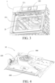
- FIG. 3 is a section view of the domestic cooking appliance 1 with the door 40 removed according to this application, where the cooking space 20 can be seen.
- the ventilation device 10 is arranged at the top of the domestic cooking appliance 1.
- the ventilation device 10 is arranged at another position on the domestic cooking appliance 1 that is preferably adjacent to the cooking space 20.
- the domestic cooking appliance 1 may be a steam oven, a steamer, or an oven, or may be another box-type appliance configured for cooking, for example, steaming and/or baking food.
- the domestic cooking appliance 1 is configured to bake and/or steam food placed in the cooking space 20 thereof.
- FIG. 4 is a perspective view of a ventilation device 10 alone according to this application.
- FIG. 5 is a section view of the ventilation device 10 according to this application.
- the ventilation device 10 is configured to discharge gas in the cooking space 20 into the surrounding environment.
- the ventilation device 10 includes a channel assembly 200, where the channel assembly 200 includes a first housing element 230 (herein, a lower housing), a second housing element 240 (herein, an upper housing), and a spacer element 250 (a spacer plate) arranged therebetween.
- a first ventilation channel 210 is configured between the first housing element 230 and the spacer element 250
- a second ventilation channel 220 is configured between the second housing element 240 and the spacer element 250
- a double-layer channel structure with upper and lower air channels is formed, for example, the first ventilation channel 210 is a lower air channel and the second ventilation channel 220 is an upper air channel.
- the first ventilation channel 210 is in communication with the cooking space 20 of the domestic cooking appliance 1
- the second ventilation channel 220 is in communication with the surrounding environment of the domestic cooking appliance 1, thereby forming a passage between the cooking space 20 and the surrounding environment, to ventilate the cooking space 20.
- the ventilation device 10 includes a fan 300, in particular, a centrifugal fan, and the fan 300 is fluidically arranged in series between the first ventilation channel 210 and the second ventilation channel 220 (refer to FIG. 11 ).
- a suction side of the fan 300 is connected to the first ventilation channel 210, and a discharge side of the fan 300 is connected to the second ventilation channel 220. Therefore, under the action of the fan 300, the gas in the cooking space 20 flows to the fan 300 through the first ventilation channel 210, and is then discharged into the surrounding environment through the second ventilation channel 220.
- a ventilation inlet 211 is configured on the first housing element 230, and the ventilation inlet 211 is in communication with the cooking space 20 of the domestic cooking appliance 1.
- the first housing element 230 constitutes at least one of limiting interfaces defining the cooking space 20.
- the first housing element 230 is a ceiling of a cavity of the domestic cooking appliance 1, and the ventilation inlet 211 is configured on the ceiling (refer to FIG. 3 ). Therefore, a simple and compact arrangement of the ventilation device 10 or the domestic cooking appliance 1 is achieved.
- the first housing element 230 constitutes any limiting interface of the cooking space 20, for example, a left side wall, a right side wall, a rear side wall, or a floor of the cavity, and/or one or more ventilation inlets 211 are configured on any limiting interface of the cooking space 20.
- a ventilation outlet 221 (refer to FIG. 5 ) is formed at edges of the second housing element 240 and the spacer element 250, and the ventilation outlet 221 is in communication with the surrounding environment of the domestic cooking appliance 1, and is configured to discharge the gas flowing past the channel assembly 200.
- the ventilation outlet 221 is arranged, for example, on a side facing the door 40.
- one or more ventilation outlets 221 are arranged at any position on the domestic cooking appliance 1 that is adjacent to the surrounding environment.
- the ventilation device 10 further includes a sensor accommodating apparatus 100, and a sensor 110 (refer to FIG. 7 and FIG. 8 ) is arranged in the sensor accommodating apparatus 100, preferably a sensor for gas composition detection, in particular, a volatile organic compound (VOC) sensor, or any other sensor suitable for use in a cooking process, for example, a temperature sensor, a humidity sensor, or a flow sensor.
- a sensor for gas composition detection in particular, a volatile organic compound (VOC) sensor
- VOC volatile organic compound
- the sensor 110 in particular, the volatile organic compound sensor, can detect composition of the gas generated by food, thereby determining a state of the food during the cooking process, for example, doneness, overheating-triggered carbonization, or presence of harmful composition. In this way, adjustment can be performed in the cooking process, for example, temperature control, steam amount control, ventilation, or air supply.
- FIG. 6 shows a sensor accommodating apparatus 100 of a ventilation device 10 alone according to this application.
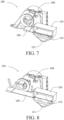
- FIG. 7 is a section view of the sensor accommodating apparatus 100 in an off state.
- FIG. 8 is a section view of the sensor accommodating apparatus 100 in an on state.
- the sensor accommodating apparatus 100 includes a protective housing 120, and a sensor 110 is arranged in an internal space of the protective housing 120.
- the protective housing 120 is configured with a housing inlet 121 connecting to a first ventilation channel 210, and a housing outlet 122 connecting to a suction side of a fan 300.
- a movable baffle 130 is arranged at the housing inlet 121, where the movable baffle 130 can be driven to move by a driving apparatus 140, to be specific, move between a closed position ( FIG. 7 ) and an open position ( FIG. 8 ).
- the driving apparatus 140 includes a motor 141 and a motor turntable 142 driven to rotate by the motor 141.
- a link 143 extends from the motor turntable 142, and the link 143 is slidably fitted into a chute 144 connected to the movable baffle 130. Therefore, rotational movement of the motor turntable 142 driven by the motor 141 can be converted into linear movement of the movable baffle 130, thereby controlling movement of the movable baffle 130 between the closed position and the open position.
- FIG. 9 schematically shows a gas flow line in a ventilation device 10 according to this application when a movable baffle 130 is closed.
- the movable baffle 130 closes a housing inlet 121, thereby keeping a sensor 110 isolated from gas in a cooking space 20.
- the gas in the cooking space 20 is discharged into the surrounding environment after merely flowing past a first ventilation channel 210, a fan 300, and a second ventilation channel 220 in sequence.
- the sensor 110 can be protected against damage when the sensor 110 is not needed to detect the gas in the cooking space 20.
- temperature of high-temperature steam may reach 400°C to 500°C.
- FIG. 10 schematically shows a gas flow line in a ventilation device 10 according to this application when a movable baffle 130 is open.
- a housing inlet 121 is released, so that a sensor accommodating apparatus 100 or a protective housing 120 forms another branch (shown by a dotted line) for gas in a cooking space 20.
- a negative pressure is formed at a housing outlet 122, so that a part of the gas flowing past a first ventilation channel 210 is drawn through the protective housing 120, that is, through a sensor 110, in particular, a volatile organic compound sensor.
- the sensor 110 can detect the gas, to obtain a needed measurement parameter, for example, gas composition.
- the gas flowing past the protective housing 120 re-enters a second ventilation channel 220 through the housing outlet 122, and is then discharged into the surrounding environment together with the gas therein.
- FIG. 11 is a sketchy schematic of a gas flow line in a ventilation device 10, where a flow branch for gas flowing past a sensor accommodating apparatus 100 is shown by a dashed line.
- FIG. 12 is a schematic block diagram of a domestic cooking appliance 1 according to this application.
- the domestic cooking appliance 1 includes a control unit 30, where the control unit 30 is configured to control a cooking process of the domestic cooking appliance 1, for example, baking/steaming temperature and time, and/or control a ventilation device 10 according to this application.
- the control unit 30 is configured to control the cooking process based on a sensor signal of a sensor 110.
- the control unit 30 can obtain composition that is of gas generated by food during the cooking process and that is measured by the sensor 110, for example, a volatile organic compound sensor, and analytically evaluate the composition.
- control unit 30 can determine a status of the food during the cooking process, thereby controlling/adjusting the cooking process accordingly. This helps implement intelligent and automatic cooking and obtain a desired cooking product.
- first and second are used only for the purpose of description, and shall not be understood as indicating or implying relative importance or implicitly specifying a quantity of indicated technical features. Therefore, a feature limited by “first” or “second” may explicitly or implicitly include one or more of the features.
- connection may be a fixed connection, a detachable connection, or an integral connection; may be a mechanical connection or an electrical connection; or may be a direct connection, an indirect connection by using an intermediary, or internal communication between two components.
Landscapes
- Engineering & Computer Science (AREA)
- Chemical & Material Sciences (AREA)
- Combustion & Propulsion (AREA)
- Mechanical Engineering (AREA)
- General Engineering & Computer Science (AREA)
- Ventilation (AREA)
Abstract
Embodiments of this application provide a ventilation device for a domestic cooking appliance. The ventilation device includes: a channel assembly, where the channel assembly has a ventilation inlet and a ventilation outlet, the ventilation inlet is in communication with a cooking space of the domestic cooking appliance, and the ventilation outlet is in communication with the surrounding environment of the domestic cooking appliance; a fan, where the fan is configured to drive gas in the cooking space of the domestic cooking appliance to flow past the channel assembly; and a sensor accommodating apparatus in which a sensor is arranged, where the sensor accommodating apparatus constitutes a branch between the ventilation inlet and the ventilation outlet, the sensor accommodating apparatus can be switched between a first state and a second state, in the first state, the sensor is kept isolated from the gas in the cooking space, and in the second state, the gas in the cooking space is allowed to flow past the sensor under the action of the fan.
Description
- This application relates to the field of domestic appliances, and in particular, to a ventilation device for a domestic cooking appliance and a domestic cooking appliance.
- In an oven, a steamer, or a steam oven in a conventional technology, because temperature and/or humidity are/is excessively high in a process of baking, grilling, steaming, or the like, a gas-sensitive sensor, for example, a volatile organic compound sensor, that may be used to control a cooking process generally cannot be arranged in a cavity of the oven or the steam oven. Therefore, disposition and protection of this type of sensor are particularly important. Currently, the oven, the steamer, or the steam oven lacks a sensor disposition system that can be resistant to a harsh environment in a cooking space and therefore can accurately collect required data.
- Embodiments of this application aim to provide an improved ventilation device for a domestic cooking appliance and a domestic cooking appliance having a corresponding ventilation device, to improve a conventional technology or at least partially resolve defects in the conventional technology.
- According to a first aspect of this application, an embodiment of this application provides a ventilation device for a domestic cooking appliance. The ventilation device includes:
- a channel assembly, where the channel assembly has a ventilation inlet and a ventilation outlet, the ventilation inlet is in communication with a cooking space of the domestic cooking appliance, and the ventilation outlet is in communication with the surrounding environment of the domestic cooking appliance;
- a fan, where the fan is configured to drive gas in the cooking space of the domestic cooking appliance to flow past the channel assembly; and
- a sensor accommodating apparatus in which a sensor is arranged, where the sensor accommodating apparatus constitutes a branch between the ventilation inlet and the ventilation outlet,
- the sensor accommodating apparatus can be switched between a first state and a second state, in the first state, the sensor is kept isolated from the gas in the cooking space, and in the second state, the gas in the cooking space is allowed to flow past the sensor under the action of the fan.
- This application mainly includes the following technical idea: The sensor with a protective housing is arranged in the channel assembly, so that the gas in the cooking space can optionally flow past the sensor or be isolated from the sensor. Therefore, when an intelligent cooking process needs to be implemented by using a signal detected by the sensor, for example, information such as composition of the gas generated by food, a ventilation channel in the sensor accommodating apparatus is open. When the sensor is not needed for detection and/or the gas in the cooking space may cause damage to the sensor (for example, due to high temperature and humidity in a cleaning process), the sensor is isolated from the gas.
- According to an optional embodiment of this application, the channel assembly is configured with a first ventilation channel and a second ventilation channel, where
- the first ventilation channel is connected to a suction side of the fan, and is also in communication with the cooking space via the ventilation inlet, and
- the second ventilation channel is connected to a discharge side of the fan, and is also in communication with the surrounding environment via the ventilation outlet.
- According to an optional embodiment of this application, the sensor accommodating apparatus includes a protective housing and a movable baffle, where the sensor is arranged in an internal space of the protective housing,
- the protective housing is configured with a housing inlet connecting to the first ventilation channel and a housing outlet connecting to a suction side of the fan, and
- the movable baffle closes the housing inlet at a first position in the first state, and releases the housing inlet at a second position in the second state.
- According to an optional embodiment of this application, the sensor accommodating apparatus includes a driving apparatus, where the driving apparatus is configured to drive the movable baffle to move between the first position and the second position.
- According to an optional embodiment of this application, the driving apparatus is configured as a slider crank mechanism driven by a motor.
- According to an optional embodiment of this application, the channel assembly includes a first housing element, a second housing element, and a spacer element arranged between the first housing element and the second housing element, where
- the first ventilation channel is configured between the first housing element and the spacer element, and
- the second ventilation channel is configured between the second housing element and the spacer element.
- According to an optional embodiment of this application, the ventilation inlet is configured on the first housing element.
- According to an optional embodiment of this application, the first housing element constitutes at least one of limiting interfaces defining the cooking space.
- According to an optional embodiment of this application, the sensor includes a sensor for gas composition detection, in particular, a volatile organic compound sensor.
- According to a second aspect of this application, an embodiment of this application provides a domestic cooking appliance, where the domestic cooking appliance has a ventilation device according to the first aspect of this application.
- According to an optional embodiment of this application, the domestic cooking appliance has a control unit, where the control unit is configured to control a cooking process based on a sensor signal of a sensor in a sensor accommodating apparatus of the ventilation device.
- Through some implementations of this application, the following technical advantages can be achieved: the sensor required for cooking is protected against a harsh condition in a cooking space, intelligent and automatic cooking is implemented by simply switching to a working state of the sensor, and a simple and compact arrangement is provided while implementing the foregoing functions.
- The principles, features, and advantages of this application may be better understood through more detailed description of this application with reference to the accompanying drawings. The accompanying drawings include:
-
FIG. 1 is a perspective view of a domestic cooking appliance according to this application; -
FIG. 2 is a cutaway top view of a domestic cooking appliance according to this application; -
FIG. 3 is a section view of a domestic cooking appliance with a door removed according to this application; -
FIG. 4 is a perspective view of a ventilation device alone according to this application; -
FIG. 5 is a section view of a ventilation device according to this application; -
FIG. 6 shows a sensor accommodating apparatus of a ventilation device alone according to this application; -
FIG. 7 is a section view of a sensor accommodating apparatus in an off state; -
FIG. 8 is a section view of a sensor accommodating apparatus in an on state; -
FIG. 9 schematically shows a gas flow line in a ventilation device according to this application when a movable baffle is closed; -
FIG. 10 schematically shows a gas flow line in a ventilation device according to this application when a movable baffle is open; -
FIG. 11 is a sketchy schematic of a gas flow line in aventilation device 10; and -
FIG. 12 is a schematic block diagram of adomestic cooking appliance 1 according to this application. - 1: Domestic cooking appliance, 10: Ventilation device, 100: Sensor accommodating apparatus, 110: Sensor, 120: Protective housing, 121: Housing inlet, 122: Housing outlet, 130: Movable baffle, 140: Driving apparatus, 141: Motor, 142: Motor turntable, 143: Link, 144: Chute, 200: Channel assembly, 210: First ventilation channel, 211: Ventilation inlet, 220: Second ventilation channel, 221: Ventilation outlet, 230: First housing element, 240: Second housing element, 250: Spacer element, 300: Fan, 20: Cooking space, 30: Control unit, 40: Door.
- To make the technical problems, technical solutions, and beneficial technical effects in this application clearer, the following further describes this application in detail with reference to the accompanying drawings and a plurality of exemplary embodiments. It should be understood that specific embodiments described herein are merely used to explain this application, and are not intended to limit the protection scope of this application.
- First, for ease of understanding, the descriptions in the background are provided herein again. In a conventional technology, an oven, a steamer, or a steam oven lacks a sensor disposition system that can be resistant to a harsh cooking environment in a cavity and therefore can accurately collect data.
- In view of at least one of the foregoing technical problems or another possible technical problem, an exemplary embodiment of this application provides a ventilation device for a domestic cooking appliance. The ventilation device includes: a channel assembly, where the channel assembly has a ventilation inlet and a ventilation outlet, the ventilation inlet is in communication with a cooking space of the domestic cooking appliance, and the ventilation outlet is in communication with the surrounding environment of the domestic cooking appliance; a fan, where the fan is configured to drive gas in the cooking space of the domestic cooking appliance to flow past the channel assembly; and a sensor accommodating apparatus in which a sensor is arranged, where the sensor accommodating apparatus constitutes a branch between the ventilation inlet and the ventilation outlet, the sensor accommodating apparatus can be switched between a first state and a second state, in the first state, the sensor is kept isolated from the gas in the cooking space, and in the second state, the gas in the cooking space is allowed to flow past the sensor under the action of the fan.
- To make this application more understandable, the following describes exemplary embodiments of this application with reference to the accompanying drawings.
-
FIG. 1 is a perspective view of adomestic cooking appliance 1 according to this application.FIG. 2 is a cutaway top view of thedomestic cooking appliance 1 according to this application, where aventilation device 10 according to this application can be seen. In this case, thedomestic cooking appliance 1 has adoor 40, and acooking space 20 is formed by the closeddoor 40 and an internal cavity of thedomestic cooking appliance 1.FIG. 3 is a section view of thedomestic cooking appliance 1 with thedoor 40 removed according to this application, where thecooking space 20 can be seen. For example, as shown inFIG. 2 , theventilation device 10 is arranged at the top of thedomestic cooking appliance 1. However, it may alternatively be considered that theventilation device 10 is arranged at another position on thedomestic cooking appliance 1 that is preferably adjacent to thecooking space 20. Herein, thedomestic cooking appliance 1 may be a steam oven, a steamer, or an oven, or may be another box-type appliance configured for cooking, for example, steaming and/or baking food. Optionally, thedomestic cooking appliance 1 is configured to bake and/or steam food placed in thecooking space 20 thereof. -
FIG. 4 is a perspective view of aventilation device 10 alone according to this application.FIG. 5 is a section view of theventilation device 10 according to this application. Herein, theventilation device 10 is configured to discharge gas in thecooking space 20 into the surrounding environment. As shown inFIG. 4 andFIG. 5 , theventilation device 10 includes achannel assembly 200, where thechannel assembly 200 includes a first housing element 230 (herein, a lower housing), a second housing element 240 (herein, an upper housing), and a spacer element 250 (a spacer plate) arranged therebetween. In this case, afirst ventilation channel 210 is configured between thefirst housing element 230 and thespacer element 250, and asecond ventilation channel 220 is configured between thesecond housing element 240 and thespacer element 250, in other words, a double-layer channel structure with upper and lower air channels is formed, for example, thefirst ventilation channel 210 is a lower air channel and thesecond ventilation channel 220 is an upper air channel. Thefirst ventilation channel 210 is in communication with thecooking space 20 of thedomestic cooking appliance 1, and thesecond ventilation channel 220 is in communication with the surrounding environment of thedomestic cooking appliance 1, thereby forming a passage between thecooking space 20 and the surrounding environment, to ventilate thecooking space 20. According to this application, theventilation device 10 includes afan 300, in particular, a centrifugal fan, and thefan 300 is fluidically arranged in series between thefirst ventilation channel 210 and the second ventilation channel 220 (refer toFIG. 11 ). A suction side of thefan 300 is connected to thefirst ventilation channel 210, and a discharge side of thefan 300 is connected to thesecond ventilation channel 220. Therefore, under the action of thefan 300, the gas in thecooking space 20 flows to thefan 300 through thefirst ventilation channel 210, and is then discharged into the surrounding environment through thesecond ventilation channel 220. - According to an optional embodiment, a
ventilation inlet 211 is configured on thefirst housing element 230, and theventilation inlet 211 is in communication with thecooking space 20 of thedomestic cooking appliance 1. Preferably, thefirst housing element 230 constitutes at least one of limiting interfaces defining thecooking space 20. For example, herein, thefirst housing element 230 is a ceiling of a cavity of thedomestic cooking appliance 1, and theventilation inlet 211 is configured on the ceiling (refer toFIG. 3 ). Therefore, a simple and compact arrangement of theventilation device 10 or thedomestic cooking appliance 1 is achieved. Alternatively, it may be considered that thefirst housing element 230 constitutes any limiting interface of thecooking space 20, for example, a left side wall, a right side wall, a rear side wall, or a floor of the cavity, and/or one ormore ventilation inlets 211 are configured on any limiting interface of thecooking space 20. According to an optional embodiment, a ventilation outlet 221 (refer toFIG. 5 ) is formed at edges of thesecond housing element 240 and thespacer element 250, and theventilation outlet 221 is in communication with the surrounding environment of thedomestic cooking appliance 1, and is configured to discharge the gas flowing past thechannel assembly 200. Herein, theventilation outlet 221 is arranged, for example, on a side facing thedoor 40. However, it may alternatively be considered that one ormore ventilation outlets 221 are arranged at any position on thedomestic cooking appliance 1 that is adjacent to the surrounding environment. - According to this application, the
ventilation device 10 further includes a sensoraccommodating apparatus 100, and a sensor 110 (refer toFIG. 7 and FIG. 8 ) is arranged in the sensoraccommodating apparatus 100, preferably a sensor for gas composition detection, in particular, a volatile organic compound (VOC) sensor, or any other sensor suitable for use in a cooking process, for example, a temperature sensor, a humidity sensor, or a flow sensor. Advantageously, thesensor 110, in particular, the volatile organic compound sensor, can detect composition of the gas generated by food, thereby determining a state of the food during the cooking process, for example, doneness, overheating-triggered carbonization, or presence of harmful composition. In this way, adjustment can be performed in the cooking process, for example, temperature control, steam amount control, ventilation, or air supply. -
FIG. 6 shows a sensoraccommodating apparatus 100 of aventilation device 10 alone according to this application.FIG. 7 is a section view of the sensoraccommodating apparatus 100 in an off state.FIG. 8 is a section view of the sensoraccommodating apparatus 100 in an on state. - As shown in
FIG. 6 to FIG. 8 , the sensoraccommodating apparatus 100 includes aprotective housing 120, and asensor 110 is arranged in an internal space of theprotective housing 120. Herein, theprotective housing 120 is configured with ahousing inlet 121 connecting to afirst ventilation channel 210, and ahousing outlet 122 connecting to a suction side of afan 300. InFIG. 6 to FIG. 8 , amovable baffle 130 is arranged at thehousing inlet 121, where themovable baffle 130 can be driven to move by a drivingapparatus 140, to be specific, move between a closed position (FIG. 7 ) and an open position (FIG. 8 ). Herein, the drivingapparatus 140 includes amotor 141 and amotor turntable 142 driven to rotate by themotor 141. Alink 143 extends from themotor turntable 142, and thelink 143 is slidably fitted into achute 144 connected to themovable baffle 130. Therefore, rotational movement of themotor turntable 142 driven by themotor 141 can be converted into linear movement of themovable baffle 130, thereby controlling movement of themovable baffle 130 between the closed position and the open position. -
FIG. 9 schematically shows a gas flow line in aventilation device 10 according to this application when amovable baffle 130 is closed. At a closed position of themovable baffle 130, themovable baffle 130 closes ahousing inlet 121, thereby keeping asensor 110 isolated from gas in acooking space 20. In this case, the gas in thecooking space 20 is discharged into the surrounding environment after merely flowing past afirst ventilation channel 210, afan 300, and asecond ventilation channel 220 in sequence. In this way, thesensor 110 can be protected against damage when thesensor 110 is not needed to detect the gas in thecooking space 20. For example, when high-temperature cleaning is performed on adomestic cooking appliance 1, temperature of high-temperature steam may reach 400°C to 500°C. By closing thehousing inlet 121 using themovable baffle 130, thesensor 110 can be prevented from damage caused by high temperature or high humidity. -
FIG. 10 schematically shows a gas flow line in aventilation device 10 according to this application when amovable baffle 130 is open. At an open position of themovable baffle 130, ahousing inlet 121 is released, so that a sensoraccommodating apparatus 100 or aprotective housing 120 forms another branch (shown by a dotted line) for gas in acooking space 20. Under the action of afan 300, a negative pressure is formed at ahousing outlet 122, so that a part of the gas flowing past afirst ventilation channel 210 is drawn through theprotective housing 120, that is, through asensor 110, in particular, a volatile organic compound sensor. In this case, thesensor 110 can detect the gas, to obtain a needed measurement parameter, for example, gas composition. After that, the gas flowing past theprotective housing 120 re-enters asecond ventilation channel 220 through thehousing outlet 122, and is then discharged into the surrounding environment together with the gas therein. -
FIG. 11 is a sketchy schematic of a gas flow line in aventilation device 10, where a flow branch for gas flowing past a sensoraccommodating apparatus 100 is shown by a dashed line. -
FIG. 12 is a schematic block diagram of adomestic cooking appliance 1 according to this application. As shown inFIG. 12 , thedomestic cooking appliance 1 includes acontrol unit 30, where thecontrol unit 30 is configured to control a cooking process of thedomestic cooking appliance 1, for example, baking/steaming temperature and time, and/or control aventilation device 10 according to this application. According to a preferred embodiment, thecontrol unit 30 is configured to control the cooking process based on a sensor signal of asensor 110. Herein, thecontrol unit 30 can obtain composition that is of gas generated by food during the cooking process and that is measured by thesensor 110, for example, a volatile organic compound sensor, and analytically evaluate the composition. Through the analytical evaluation, thecontrol unit 30 can determine a status of the food during the cooking process, thereby controlling/adjusting the cooking process accordingly. This helps implement intelligent and automatic cooking and obtain a desired cooking product. In descriptions of embodiments of this application, it should be understood that the terms such as "first" and "second" are used only for the purpose of description, and shall not be understood as indicating or implying relative importance or implicitly specifying a quantity of indicated technical features. Therefore, a feature limited by "first" or "second" may explicitly or implicitly include one or more of the features. - In this specification, unless otherwise explicitly specified and defined, terms such as "install", "connect", and "connection" shall be understood in a broad sense. For example, the connection may be a fixed connection, a detachable connection, or an integral connection; may be a mechanical connection or an electrical connection; or may be a direct connection, an indirect connection by using an intermediary, or internal communication between two components. A person of ordinary skill in the art can understand meanings of the terms in the present disclosure based on situations.
- Although specific implementations have been described above, these implementations are not intended to limit the scope of the present application disclosure, even if only one implementation is described with respect to specific features. The feature example provided in the present application disclosure is intended to be illustrative rather than limiting, unless otherwise stated. In a specific implementation, according to an actual requirement, a plurality of features may be combined with each other when technically feasible. In particular, features in different embodiments may also be combined with each other. Various alternatives, changes, and modifications may also be conceived without departing from the spirit and scope of this application.
Claims (10)
- A ventilation device (10) for a domestic cooking appliance (1), wherein the ventilation device (10) comprises:a channel assembly (200), wherein the channel assembly (200) has a ventilation inlet (211) and a ventilation outlet (221), the ventilation inlet (211) is in communication with a cooking space (20) of the domestic cooking appliance (1),and the ventilation outlet (221) is in communication with the surrounding environment of the domestic cooking appliance (1);a fan (300), wherein the fan (300) is configured to drive gas in the cooking space (20) of the domestic cooking appliance (1) to flow past the channel assembly (200); anda sensor accommodating apparatus (100) in which a sensor (110) is arranged,wherein the sensor accommodating apparatus (100) constitutes a branch between the ventilation inlet (211) and the ventilation outlet (221),the sensor accommodating apparatus (100) can be switched between a first state and a second state,in the first state, the sensor (110) is kept isolated from the gas in the cooking space (20),and in the second state, the gas in the cooking space (20) is allowed to flow past the sensor (110) under the action of the fan (300).
- The ventilation device (10) according to claim 1, whereinthe channel assembly (200) is configured with a first ventilation channel (210) and a second ventilation channel (220),the first ventilation channel (210) is connected to a suction side of the fan (300), and is also in communication with the cooking space (20) via the ventilation inlet (211), andthe second ventilation channel (220) is connected to a discharge side of the fan (300), and is also in communication with the surrounding environment via the ventilation outlet (221).
- The ventilation device (10) according to claim 2, whereinthe sensor accommodating apparatus (100) comprises a protective housing (120) and a movable baffle (130), the sensor (110) is arranged in an internal space of the protective housing (120),the protective housing (120) is configured with a housing inlet (121) in communication with the first ventilation channel (210) and a housing outlet (122) in communication with the suction side of the fan (300), andthe movable baffle (130) closes the housing inlet (121) at a first position in the first state, and releases the housing inlet (121) at a second position in the second state.
- The ventilation device (10) according to claim 3, wherein
the sensor accommodating apparatus (100) comprises a driving apparatus (140), and the driving apparatus (140) is configured to drive the movable baffle (130) to move between the first position and the second position. - The ventilation device (10) according to claim 4, wherein
the driving apparatus (140) is configured as a slider crank mechanism driven by a motor (141). - The ventilation device (10) according to claim 2, whereinthe channel assembly (200) comprises a first housing element (230), a second housing element (240), and a spacer element (250) arranged between the first housing element (230) and the second housing element (240),the first ventilation channel (210) is configured between the first housing element (230) and the spacer element (250), andthe second ventilation channel (220) is configured between the second housing element (240) and the spacer element (250).
- The ventilation device (10) according to claim 6, whereinthe ventilation inlet (211) is configured on the first housing element (230), and/orthe first housing element (230) constitutes at least one of limiting interfaces defining the cooking space (20).
- The ventilation device (10) according to any one of claims 1 to 7, wherein
the sensor (110) comprises a sensor for gas composition detection, in particular, a volatile organic compound sensor. - A domestic cooking appliance (1), wherein the domestic cooking appliance (1) has the ventilation device (10) according to any one of claims 1 to 8.
- The domestic cooking appliance (1) according to claim 9, wherein
the domestic cooking appliance (1) has a control unit (30), and the control unit (30) is configured to control a cooking process based on a sensor signal of the sensor (110) in the sensor accommodating apparatus (100) of the ventilation device (10).
Applications Claiming Priority (1)
| Application Number | Priority Date | Filing Date | Title |
|---|---|---|---|
| CN202310712847.1A CN119138762A (en) | 2023-06-15 | 2023-06-15 | Ventilation device for household cooking appliance and household cooking appliance |
Publications (1)
| Publication Number | Publication Date |
|---|---|
| EP4477959A1 true EP4477959A1 (en) | 2024-12-18 |
Family
ID=91539800
Family Applications (1)
| Application Number | Title | Priority Date | Filing Date |
|---|---|---|---|
| EP24181951.5A Pending EP4477959A1 (en) | 2023-06-15 | 2024-06-13 | Ventilation device for domestic cooking appliance and domestic cooking appliance |
Country Status (2)
| Country | Link |
|---|---|
| EP (1) | EP4477959A1 (en) |
| CN (1) | CN119138762A (en) |
Citations (6)
| Publication number | Priority date | Publication date | Assignee | Title |
|---|---|---|---|---|
| JPS59191813A (en) * | 1984-03-27 | 1984-10-31 | Matsushita Electric Ind Co Ltd | food heater |
| EP1966543B1 (en) * | 2005-12-30 | 2011-10-12 | Arçelik A.S. | Oven with sensor |
| EP2655976B1 (en) * | 2010-12-20 | 2016-10-26 | BSH Hausgeräte GmbH | Cooking appliance having vapor extraction means |
| WO2022074062A1 (en) * | 2020-10-09 | 2022-04-14 | Bruckbauer, Wilhelm | Device for treating vapors |
| US20220167646A1 (en) * | 2020-11-27 | 2022-06-02 | V-Zug Ag | Cooking method for operating a cooking device |
| DE102021125232A1 (en) * | 2021-09-29 | 2023-03-30 | Miele & Cie. Kg | Vapor extraction device for a cooking appliance, cooking system and method for operating a vapor extraction device or a cooking system |
-
2023
- 2023-06-15 CN CN202310712847.1A patent/CN119138762A/en active Pending
-
2024
- 2024-06-13 EP EP24181951.5A patent/EP4477959A1/en active Pending
Patent Citations (6)
| Publication number | Priority date | Publication date | Assignee | Title |
|---|---|---|---|---|
| JPS59191813A (en) * | 1984-03-27 | 1984-10-31 | Matsushita Electric Ind Co Ltd | food heater |
| EP1966543B1 (en) * | 2005-12-30 | 2011-10-12 | Arçelik A.S. | Oven with sensor |
| EP2655976B1 (en) * | 2010-12-20 | 2016-10-26 | BSH Hausgeräte GmbH | Cooking appliance having vapor extraction means |
| WO2022074062A1 (en) * | 2020-10-09 | 2022-04-14 | Bruckbauer, Wilhelm | Device for treating vapors |
| US20220167646A1 (en) * | 2020-11-27 | 2022-06-02 | V-Zug Ag | Cooking method for operating a cooking device |
| DE102021125232A1 (en) * | 2021-09-29 | 2023-03-30 | Miele & Cie. Kg | Vapor extraction device for a cooking appliance, cooking system and method for operating a vapor extraction device or a cooking system |
Also Published As
| Publication number | Publication date |
|---|---|
| CN119138762A (en) | 2024-12-17 |
Similar Documents
| Publication | Publication Date | Title |
|---|---|---|
| US20170292713A1 (en) | System and Method for Controlling Oven Humidity | |
| EP3867576B1 (en) | An exhaust hood comprising a temperature sensor | |
| EP3867575B1 (en) | An exhaust hood for detecting the cooking device type | |
| KR101720995B1 (en) | Gas rice-cooker with dual exhaust pipe | |
| CN106580120A (en) | Oven capable of collecting food images | |
| CN110870699A (en) | Oven and operating method thereof | |
| EP3933275B1 (en) | Cooking appliance and method for controlling the same | |
| US20210172610A1 (en) | Oven appliance having a humidity sensor | |
| JP2010071615A (en) | Heating cooker | |
| CN113531614B (en) | Integrated stove capable of distributing air volume and control method thereof | |
| EP4276364A1 (en) | An exhaust hood with improved automatic operation performance | |
| CN112610993B (en) | Control method and control device of oil smoke suction device and oil smoke suction device | |
| US20100031949A1 (en) | Fan apparency arrangement for an appliance | |
| CN119138762A (en) | Ventilation device for household cooking appliance and household cooking appliance | |
| JP3125464B2 (en) | Fan lock detection device for built-in cooking equipment | |
| KR100217191B1 (en) | Cooker | |
| CN110906395B (en) | Control method of range hood | |
| CN110645607B (en) | Range hood with thermal image detection function and control method thereof | |
| JP5300930B2 (en) | Cooker | |
| CN113958988A (en) | Range hood and control method of range hood | |
| JP2697285B2 (en) | Smoke exhaust system | |
| CN223247978U (en) | Steam oven | |
| JP2019215091A (en) | Electronic microwave with ventilation fan and cooking system | |
| EP4293288A1 (en) | Exhaust hood with automatic operation performance | |
| EP4386269A1 (en) | An exhaust hood comprising a temperature sensor |
Legal Events
| Date | Code | Title | Description |
|---|---|---|---|
| PUAI | Public reference made under article 153(3) epc to a published international application that has entered the european phase |
Free format text: ORIGINAL CODE: 0009012 |
|
| STAA | Information on the status of an ep patent application or granted ep patent |
Free format text: STATUS: THE APPLICATION HAS BEEN PUBLISHED |
|
| AK | Designated contracting states |
Kind code of ref document: A1 Designated state(s): AL AT BE BG CH CY CZ DE DK EE ES FI FR GB GR HR HU IE IS IT LI LT LU LV MC ME MK MT NL NO PL PT RO RS SE SI SK SM TR |
|
| STAA | Information on the status of an ep patent application or granted ep patent |
Free format text: STATUS: REQUEST FOR EXAMINATION WAS MADE |
|
| 17P | Request for examination filed |
Effective date: 20250618 |