EP4477953A1 - Injection nozzle and combustion device - Google Patents
Injection nozzle and combustion device Download PDFInfo
- Publication number
- EP4477953A1 EP4477953A1 EP22926058.3A EP22926058A EP4477953A1 EP 4477953 A1 EP4477953 A1 EP 4477953A1 EP 22926058 A EP22926058 A EP 22926058A EP 4477953 A1 EP4477953 A1 EP 4477953A1
- Authority
- EP
- European Patent Office
- Prior art keywords
- wall
- fuel
- passage
- air
- injection nozzle
- Prior art date
- Legal status (The legal status is an assumption and is not a legal conclusion. Google has not performed a legal analysis and makes no representation as to the accuracy of the status listed.)
- Pending
Links
Images



Classifications
-
- F—MECHANICAL ENGINEERING; LIGHTING; HEATING; WEAPONS; BLASTING
- F23—COMBUSTION APPARATUS; COMBUSTION PROCESSES
- F23R—GENERATING COMBUSTION PRODUCTS OF HIGH PRESSURE OR HIGH VELOCITY, e.g. GAS-TURBINE COMBUSTION CHAMBERS
- F23R3/00—Continuous combustion chambers using liquid or gaseous fuel
- F23R3/002—Wall structures
-
- F—MECHANICAL ENGINEERING; LIGHTING; HEATING; WEAPONS; BLASTING
- F23—COMBUSTION APPARATUS; COMBUSTION PROCESSES
- F23K—FEEDING FUEL TO COMBUSTION APPARATUS
- F23K5/00—Feeding or distributing other fuel to combustion apparatus
-
- F—MECHANICAL ENGINEERING; LIGHTING; HEATING; WEAPONS; BLASTING
- F23—COMBUSTION APPARATUS; COMBUSTION PROCESSES
- F23R—GENERATING COMBUSTION PRODUCTS OF HIGH PRESSURE OR HIGH VELOCITY, e.g. GAS-TURBINE COMBUSTION CHAMBERS
- F23R3/00—Continuous combustion chambers using liquid or gaseous fuel
- F23R3/02—Continuous combustion chambers using liquid or gaseous fuel characterised by the air-flow or gas-flow configuration
- F23R3/04—Air inlet arrangements
- F23R3/10—Air inlet arrangements for primary air
- F23R3/12—Air inlet arrangements for primary air inducing a vortex
- F23R3/14—Air inlet arrangements for primary air inducing a vortex by using swirl vanes
-
- F—MECHANICAL ENGINEERING; LIGHTING; HEATING; WEAPONS; BLASTING
- F23—COMBUSTION APPARATUS; COMBUSTION PROCESSES
- F23R—GENERATING COMBUSTION PRODUCTS OF HIGH PRESSURE OR HIGH VELOCITY, e.g. GAS-TURBINE COMBUSTION CHAMBERS
- F23R3/00—Continuous combustion chambers using liquid or gaseous fuel
- F23R3/28—Continuous combustion chambers using liquid or gaseous fuel characterised by the fuel supply
-
- F—MECHANICAL ENGINEERING; LIGHTING; HEATING; WEAPONS; BLASTING
- F23—COMBUSTION APPARATUS; COMBUSTION PROCESSES
- F23R—GENERATING COMBUSTION PRODUCTS OF HIGH PRESSURE OR HIGH VELOCITY, e.g. GAS-TURBINE COMBUSTION CHAMBERS
- F23R3/00—Continuous combustion chambers using liquid or gaseous fuel
- F23R3/28—Continuous combustion chambers using liquid or gaseous fuel characterised by the fuel supply
- F23R3/286—Continuous combustion chambers using liquid or gaseous fuel characterised by the fuel supply having fuel-air premixing devices
Definitions
- the present disclosure relates to an injection nozzle and a combustion device.
- This application claims the benefit of priority to Japanese Patent Application No. 2022-17901 filed on February 8, 2022 , and contents thereof are incorporated herein.
- a gas turbine system that combusts fuel in a combustor to obtain power has been used.
- the gas turbine system for example, there exists a gas turbine system that uses a fuel injection nozzle configured to premix fuel with air and inject it into a combustor, as disclosed in Patent Literature 1. Through premixing of the fuel with sufficient air to perform lean combustion, emission of NOx is suppressed.
- Patent Literature 1 JP 5472863 B2
- a fuel passage for allowing fuel to flow therethrough and an air passage for allowing air to flow therethrough are formed by assembling a plurality of members.
- the fuel when the plurality of members are assembled to form the fuel passage, due to machining accuracy, assembly errors, or the like, the fuel sometimes flows through the fuel passage unevenly, resulting in deteriorated combustibility in a combustor.
- An object of the present disclosure is to provide an injection nozzle and a combustion device capable of improving combustibility.
- an injection nozzle including: an inner wall having a cylindrical shape; an outer wall having a cylindrical shape and being formed integrally with the inner wall through intermediation of a connection portion; a fuel passage having an annular shape and being formed between the inner wall and the outer wall; and an inner air passage formed on an inner side of the inner wall.
- the injection nozzle may include a swirling portion that is formed integrally with at least one of the inner wall and the outer wall and arranged in the fuel passage obliquely to a circumferential direction of the inner wall and the outer wall.
- the injection nozzle may include a swirling blade that is formed integrally with the inner wall and arranged in the inner air passage obliquely to the circumferential direction of the inner wall.
- the injection nozzle may include: a shaft portion arranged on a center axis of the inner air passage and formed integrally with the swirling blade; a distribution portion formed inside the shaft portion; and a fuel communication passage formed inside the swirling blade and allowing communication between the distribution portion and the fuel passage.
- the injection nozzle may include: an air supply passage connected to the inner air passage and extending tangentially to the inner air passage; and a fuel communication passage that is formed so as to separate from the air supply passage in the circumferential direction, and communicates with the fuel passage.
- the combustion device includes the above-mentioned injection nozzle.
- combustibility can be improved.
- FIG. 1 is a schematic view for illustrating a configuration of a gas turbine system 1 according to an embodiment.
- the gas turbine system 1 includes a turbocharger 11, a power generator 12, a combustor 13, an injection nozzle mechanism 14, a fuel tank 15, and a flow rate control valve 16.
- the combustor 13, the injection nozzle mechanism 14, the fuel tank 15, and the flow rate control valve 16 are included in a combustion device 10.
- the turbocharger 11 includes a compressor 11a and a turbine 11b.
- the compressor 11a and the turbine 11b rotate integrally.
- the compressor 11a and the turbine 11b are coupled by a shaft.
- the compressor 11a is provided in an intake flow passage 21 connected to the combustor 13. Air to be supplied to the combustor 13 flows through the intake flow passage 21.
- An intake port (not shown) is formed at an upstream-side end portion of the intake flow passage 21. The intake port allows air to be introduced from an outside. The air introduced through the intake port passes through the compressor 11a and is sent to the combustor 13. The compressor 11a compresses the air and discharges the compressed air to a downstream side.
- the turbine 11b is provided in an exhaust flow passage 22 connected to the combustor 13.
- An exhaust gas discharged from the combustor 13 flows through the exhaust flow passage 22.
- An exhaust port (not shown) is formed at a downstream-side end portion of the exhaust flow passage 22. The exhaust port allows the exhaust gas to be discharged to the outside.
- the exhaust gas discharged from the combustor 13 passes through the turbine 11b and is sent to the exhaust port.
- the turbine 11b is rotated by the exhaust gas to generate rotational power.
- the power generator 12 is connected to the turbocharger 11.
- the power generator 12 generates electric power with use of the rotational power generated by the turbocharger 11.
- the combustor 13 includes a casing 13a, a liner 13b, and a combustion chamber 13c.
- the casing 13a has a substantially cylindrical shape.
- the liner 13b is provided inside the casing 13a.
- the liner 13b has a substantially cylindrical shape.
- the liner 13b is arranged coaxially with the casing 13a.
- the combustion chamber 13c is formed inside the liner 13b. That is, an interior space of the liner 13b corresponds to the combustion chamber 13c.
- the combustion chamber 13c is a space having a substantially cylindrical shape.
- the exhaust flow passage 22 is connected to the combustion chamber 13c.
- a space S is defined between an inner surface of the casing 13a and an outer surface of the liner 13b.
- the intake flow passage 21 is connected to the space S. Air is fed into the space S from the compressor 11a via the intake flow passage 21.
- An opening is formed in an end portion (left end portion in FIG. 1 ) of the liner 13b on a side that air is fed from the compressor 11a.
- a plate P is provided in the vicinity of the opening in the end portion of the liner 13b.
- the injection nozzle mechanism 14 is provided on the plate P.
- the plate P retains the injection nozzle mechanism 14.
- An opening is formed in a center of the plate P.
- a gas mixture of fuel and air to be injected from the injection nozzle mechanism 14 is introduced into the combustion chamber 13c through the opening of the plate P.
- the injection nozzle mechanism 14 includes an injection nozzle 100 and a fuel supply pipe 150.
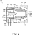
- FIG. 2 is a schematic cross-sectional view for illustrating a configuration of the injection nozzle 100 according to the present embodiment.
- the injection nozzle 100 includes an inner wall 101, a first outer wall 102, a second outer wall 103, an inner air passage 104, a shaft portion 105, inner swirling blades 106, a connection portion 107, a fuel passage 108, a resistance portion 109, a swirling portion 110, an outer air passage 111, and outer swirling blades 112.
- the inner wall 101, the first outer wall 102, and the second outer wall 103 are each formed into a cylindrical shape.
- the present disclosure is not limited thereto, and the inner wall 101, the first outer wall 102, and the second outer wall 103 may be formed into, for example, a truncated cone shape.
- the inner wall 101, the first outer wall 102, and the second outer wall 103 may have an inclined shape inclined in a direction in which a part of the cylinder comes close to or separates away from a center axis.
- the inner wall 101, the first outer wall 102, and the second outer wall 103 may have such an inclined shape that at least a part of the cylinder is inclined along a center axis direction.
- the inner wall 101, the first outer wall 102, and the second outer wall 103 separate from each other in a radial direction.
- the inner wall 101 is arranged radially inward of the first outer wall 102 and the second outer wall 103.
- the first outer wall 102 is arranged between the inner wall 101 and the second outer wall 103, and is arranged radially outward of the inner wall 101 and radially inward of the second outer wall 103.
- the second outer wall 103 is arranged radially outward of the inner wall 101 and the first outer wall 102.
- the second outer wall 103 is connected to the plate P (see FIG. 1 ).
- the inner air passage 104 is formed by an inner peripheral surface of the inner wall 101.
- An air inlet 104a is formed at one end of the inner air passage 104, and an air outlet 104b is formed at another end thereof.
- the air inlet 104a communicates with the space S (see FIG. 1 ) into which the air is fed from the compressor 11a.
- the air flows through the inner air passage 104 from the air inlet 104a toward the air outlet 104b.
- the shaft portion 105 and the inner swirling blades 106 are provided in the inner air passage 104.
- the shaft portion 105 is formed into a substantially cylindrical shape.
- the shaft portion 105 is arranged on the center axis of the inner air passage 104.
- the plurality of inner swirling blades 106 are provided on an outer peripheral surface of the shaft portion 105 so as to separate from each other in a circumferential direction.
- the plurality of inner swirling blades 106 are arranged at equal intervals in the circumferential direction of the shaft portion 105.
- the inner swirling blades 106 are connected to the outer peripheral surface of the shaft portion 105 and the inner peripheral surface of the inner wall 101.
- the inner swirling blades 106 are arranged in the inner air passage 104 obliquely to the circumferential direction of the inner wall 101 and the shaft portion 105.
- the inner swirling blades 106 swirl the air in a clockwise or counterclockwise direction about the center axis of the inner air passage 104.
- connection portion 107 connects the inner wall 101 and the first outer wall 102 to each other.
- the connection portion 107 is provided on a side of the inner wall 101 including the air inlet 104a, and connects the inner wall 101 and the first outer wall 102 to each other.
- the fuel passage 108 is formed between the inner wall 101 and the first outer wall 102.
- the fuel passage 108 is formed into an annular shape.
- a fuel communication passage 108a is connected to a part of the fuel passage 108 in the circumferential direction, and at another end thereof, a fuel discharge port 108b is formed.
- the fuel flows through the fuel passage 108 from the fuel communication passage 108a toward the fuel discharge port 108b.
- the resistance portion 109 and the swirling portion 110 are provided in the fuel passage 108.
- the resistance portion 109 is provided upstream of the swirling portion 110. However, the present disclosure is not limited thereto, and the resistance portion 109 may be provided downstream of the swirling portion 110.
- the resistance portion 109 is, for example, a protrusion formed over an entire circumference of an outer peripheral surface of the inner wall 101 and protruding radially from the outer peripheral surface of the inner wall 101 toward an inner peripheral surface of the first outer wall 102.
- a gap is defined between the resistance portion 109 and the inner peripheral surface of the first outer wall 102 so as to allow the fuel to flow therethrough. Owing to the resistance portion 109, a flow rate of the fuel flowing in the fuel passage 108 can be made uniform in the circumferential direction.
- the resistance portion 109 may be a protrusion formed over the entire circumference of the inner peripheral surface of the first outer wall 102 and protruding radially from the inner peripheral surface of the first outer wall 102 toward the outer peripheral surface of the inner wall 101. Further, a pair of resistance portions 109 may be formed over the entire circumference of the outer peripheral surface of the inner wall 101 and the entire circumference of the inner peripheral surface of the first outer wall 102.
- the pair of resistance portions 109 are, for example, protrusions that are arranged to be opposed to each other in the radial direction and protrude in directions of approaching to each other.
- the resistance portion 109 is the protrusion that is formed on at least one of the inner wall 101 and the first outer wall 102 and reduces a cross-sectional area of the flow passage of the fuel passage 108.
- the resistance portion 109 is not limited to a protrusion, and may be, for example, a slit formed in at least one of the outer peripheral surface of the inner wall 101 and the inner peripheral surface of the first outer wall 102. A plurality of slits may be formed so as to separate from each other in the circumferential direction.
- the resistance portion 109 may be a hole, such as an orifice, formed between the inner wall 101 and the first outer wall 102. A plurality of holes may be formed so as to separate from each other in the circumferential direction.
- the swirling portion 110 is formed on, for example, the inner wall 101, and at least a part of the swirling portion 110 is arranged obliquely to the circumferential direction of the inner wall 101. Owing to oblique arrangement of the swirling portion 110, the fuel can be swirled in a clockwise or counterclockwise direction about the center axis of the inner air passage 104.
- the swirling portion 110 may be formed on the first outer wall 102 or on both the inner wall 101 and the first outer wall 102. That is, the swirling portion 110 may be formed on at least one of the inner wall 101 and the first outer wall 102, and may be arranged in the fuel passage 108 obliquely to the circumferential direction of the inner wall 101 and the first outer wall 102.
- the outer air passage 111 is formed between an inner peripheral surface of the second outer wall 103 and an outer peripheral surface of the first outer wall 102.
- the outer air passage 111 has an annular shape.
- An air inlet 111a is formed at one end of the outer air passage 111, and an injection port 111b is formed at another end thereof.
- the air inlet 111a communicates with the space S into which the air is fed from the compressor 11a.
- the air flows through the outer air passage 111 from the air inlet 111a toward the injection port 111b.
- the outer swirling blades 112 are provided in the outer air passage 111.
- the plurality of outer swirling blades 112 are provided on the outer peripheral surface of the first outer wall 102 so as to separate from each other in the circumferential direction.
- the plurality of outer swirling blades 112 are arranged at equal intervals in the circumferential direction of the first outer wall 102.
- the outer swirling blades 112 are connected to the outer peripheral surface of the first outer wall 102 and the inner peripheral surface of the second outer wall 103.
- the outer swirling blades 112 swirl the air in a clockwise or counterclockwise direction about the center axis of the outer air passage 111.
- the fuel supply pipe 150 is connected at one end to the connection portion 107 and the outer peripheral surface of the first outer wall 102, and connected at another end to a flow passage 24 (see FIG. 1 ) to be described later.
- the fuel supply pipe 150 supplies the fuel from the flow passage 24 to the injection nozzle 100.
- a fuel supply passage 160 is formed in the fuel supply pipe 150.
- the fuel supply passage 160 communicates with the fuel passage 108 via the fuel communication passage 108a.
- the fuel is stored in the fuel tank 15.
- the fuel is, for example, natural gas or hydrogen.
- the hydrogen may be liquid or gaseous in the fuel tank 15.
- the fuel tank 15 is connected to the flow rate control valve 16 via a flow passage 23.
- the flow rate control valve 16 is connected to the fuel supply pipe 150 via the flow passage 24.
- the fuel stored in the fuel tank 15 is supplied into the fuel supply pipe 150 via the flow passage 23, the flow rate control valve 16, and the flow passage 24.
- the flow rate control valve 16 controls (i.e., adjusts) a flow rate of the fuel to be supplied from the fuel tank 15 into the fuel supply pipe 150. Through adjustment of an opening degree of the flow rate control valve 16, a supply amount of the fuel from the fuel tank 15 into the fuel supply pipe 150 is adjusted.
- the fuel supply passage 160 of the fuel supply pipe 150 is connected to the fuel communication passage 108a.
- the fuel is supplied from the fuel supply pipe 150 into the fuel passage 108 via the fuel communication passage 108a.
- the fuel supplied into the fuel passage 108 merges with the air having flowed through the inner air passage 104, and is mixed therewith, when the fuel is injected from the fuel discharge port 108b.
- the air flowing through the inner air passage 104 is swirled by the inner swirling blades 106, and the fuel flowing through the fuel passage 108 is swirled by the swirling portion 110.
- a shear force atomizes the fuel and accelerates mixing of the air and the fuel.
- a swirling direction of the air caused by the inner swirling blades 106 and a swirling direction of the fuel caused by the swirling portion 110 are the same direction.
- the present disclosure is not limited thereto, and the swirling direction of the air caused by the inner swirling blades 106 and the swirling direction of the fuel caused by the swirling portion 110 may be directions opposite to each other.
- the gas mixture of air and fuel is discharged from a gas mixture injection port 102a of the first outer wall 102 and flows into the outer air passage 111 of the second outer wall 103.
- the gas mixture discharged from the gas mixture injection port 102a merges with the air having flowed through the outer air passage 111, and is mixed therewith.
- the air flowing through the outer air passage 111 is swirled by the outer swirling blades 112.
- a shear force atomizes the fuel and accelerates mixing of the air and the gas mixture.
- the swirling direction of the air caused by the outer swirling blades 112 and the swirling direction of the fuel caused by the inner swirling blades 106 and the swirling portion 110 are the same direction.
- the present disclosure is not limited thereto, and the swirling direction of the air caused by the outer swirling blades 112 and the swirling direction of the air caused by the inner swirling blades 106 or the swirling direction of the fuel caused by the swirling portion 110 may be directions opposite to each other.
- the gas mixture mixed in the second outer wall 103 is injected from the injection port 111b into the combustion chamber 13c.
- the fuel may flow through the fuel passage unevenly or the fuel may leak from gaps between the plurality of members due to machining accuracy, assembly errors, or the like.
- combustibility in the combustor may deteriorate.
- parts forming the injection nozzle 100 are integrally formed.
- the inner wall 101, the first outer wall 102, the second outer wall 103, the shaft portion 105, the inner swirling blades 106, the connection portion 107, the resistance portion 109, the swirling portion 110, and the outer swirling blades 112 are integrally formed by additive manufacturing technology.
- the inner wall 101 and the first outer wall 102 are integrally formed.
- a gap between the inner wall 101 and the first outer wall 102 can be eliminated, thereby being capable of preventing fuel leakage.
- no machining or assembly is required.
- a radial width of the fuel passage 108 can be made uniform over the entire circumference. That is, it is possible to reduce eccentricity between the center axis of the inner wall 101 having a cylindrical shape and the center axis of the first outer wall 102 having a cylindrical shape, which is caused by assembly. As a result, the flow rate of the fuel in the circumferential direction of the fuel passage 108 can be made uniform, thereby being capable of improving the combustibility in the combustion chamber 13c.
- the resistance portion 109 is formed integrally with the inner wall 101 or the first outer wall 102.
- the swirling portion 110 is formed integrally with the inner wall 101 or the first outer wall 102.
- the inner swirling blades 106 are formed integrally with the inner wall 101
- the outer swirling blades 112 are formed integrally with the first outer wall 102.
- FIG. 3 is a schematic cross-sectional view for illustrating a configuration of an injection nozzle 200 according to a first modification example.
- Components that are substantially the same as those of the injection nozzle 100 according to the above-mentioned embodiment are denoted by the same reference symbols, and descriptions thereof are omitted.
- the injection nozzle 200 according to the first modification example differs from the above-mentioned embodiment in that fuel communication passages 208a are formed in the inner swirling blades 106 and a distribution portion 210 is formed in the shaft portion 105.
- the inner wall 101, the first outer wall 102, the second outer wall 103, the shaft portion 105, the inner swirling blades 106, the connection portion 107, the resistance portion 109, the swirling portion 110, and the outer swirling blades 112 are integrally formed by the additive manufacturing technology.
- the fuel communication passages 208a and the distribution portion 210 are formed in the inner swirling blades 106 and the shaft portion 105, respectively.
- the distribution portion 210 is formed inside the shaft portion 105, and is an internal space into which the fuel is supplied.
- the fuel supply pipe 150 is connected to the shaft portion 105.
- the fuel supply passage 160 of the fuel supply pipe 150 is connected to the distribution portion 210.
- the distribution portion 210 communicates with the fuel supply passage 160.
- the plurality of fuel communication passages 208a are connected to the distribution portion 210.
- the fuel communication passages 208a each have the same shape and size.
- One fuel communication passage 208a is formed inside one inner swirling blade 106.
- Each fuel communication passage 208a is connected at one end to the distribution portion 210, and connected at another end to the fuel passage 108.
- the fuel having passed through the fuel supply passage 160 of the fuel supply pipe 150 is supplied to the distribution portion 210.
- the distribution portion 210 evenly distributes the fuel that is supplied from the fuel supply passage 160 to each of the fuel communication passages 208a.
- the fuel communication passages 208a supply the fuel that is distributed by the distribution portion 210 to the fuel passage 108.
- the plurality of inner swirling blades 106 are arranged at equal intervals in the circumferential direction of the shaft portion 105, and thus the plurality of fuel communication passages 208a can supply the fuel evenly over the entire circumference of the fuel passage 108.
- the fuel communication passages 208a are formed in the inner swirling blades 106.
- the injection nozzle 200 can be downsized as compared to that according to the above-mentioned embodiment.
- the fuel supply pipe 150 is connected to the shaft portion 105 but is not connected to the outer peripheral surface of the first outer wall 102.
- inhibition of air flow into the outer air passage 111 by the fuel supply pipe 150 can be reduced.
- FIG. 4 is a schematic cross-sectional view for illustrating a configuration of an injection nozzle 300 according to a second modification example.
- Components that are substantially the same as those of the injection nozzle 100 according to the above-mentioned embodiment are denoted by the same reference symbols, and descriptions thereof are omitted.
- the injection nozzle 300 according to the second modification example differs from the above-mentioned embodiment in that a plurality of air supply passages 310 are provided instead of the inner swirling blades 106.
- a configuration in which the inner swirling blades 106 cause the air to swirl is hereinafter also referred to as an axial swirler, and a configuration in which the air supply passages 310, which are described later, cause the air to swirl is hereinafter also referred to as a tangential swirler.
- the injection nozzle 300 differs from the above-mentioned embodiment in that a distribution portion 320 and a plurality of fuel communication passages 308a are formed in the connection portion 107.
- the inner wall 101, the first outer wall 102, the second outer wall 103, the shaft portion 105, the connection portion 107, the resistance portion 109, the swirling portion 110, and the outer swirling blades 112 are integrally formed by the additive manufacturing technology.
- the plurality of air supply passages 310, the plurality of fuel communication passages 308a, and the distribution portion 320 are formed in the connection portion 107.
- FIG. 5 is a schematic cross-sectional view of the plurality of air supply passages 310.
- the plurality of air supply passages 310 are formed in the connection portion 107 so as to be connected to the inner air passage 104 and separate from each other in the circumferential direction.
- four air supply passages 310 are formed at equal intervals in the circumferential direction of the inner air passage 104.
- the present disclosure is not limited thereto, and the plurality of air supply passages 310 may be formed at unequal intervals in the circumferential direction of the inner air passage 104.
- the number of the air supply passages 310 may be one, two, or three, or five or more air supply passages 310 may be formed.
- Each air supply passage 310 is connected at one end to an outer edge portion of the inner air passage 104, and is opened at another end in an outer peripheral surface of the connection portion 107 or the first outer wall 102.
- the air supply passages 310 communicate with the space S (see FIG. 1 ) into which the air is fed from the compressor 11a.
- the air supply passages 310 extend tangentially to an outer periphery of the inner air passage 104. This can cause the air supplied into the inner air passage 104 to swirl even when the inner swirling blades 106 are not provided.
- the injection nozzle 300 according to the second modification example may include air supply passages similar to the plurality of air supply passages 310 described above instead of the outer swirling blades 112.
- the distribution portion 320 is formed inside the connection portion 107, and is an internal space into which the fuel is supplied.
- the fuel supply pipe 150 is connected to the connection portion 107.
- the fuel supply passage 160 of the fuel supply pipe 150 is connected to the distribution portion 320.
- the distribution portion 320 communicates with the fuel supply passage 160.
- the plurality of fuel communication passages 308a are connected to the distribution portion 320.
- the plurality of fuel communication passages 308a are formed in the connection portion 107, and are formed so as to separate from each other in the circumferential direction of the inner air passage 104 as illustrated in FIG. 5 .
- the plurality of fuel communication passages 308a are formed, for example, at equal intervals in the circumferential direction of the inner air passage 104. However, the present disclosure is not limited thereto, and the plurality of fuel communication passages 308a may be formed at unequal intervals in the circumferential direction of the inner air passage 104.
- the fuel communication passages 308a each have the same shape and size
- Each fuel communication passage 308a is connected at one end to the distribution portion 320, and connected at another end to the fuel passage 108.
- Each fuel communication passage 308a extends along the center axis direction of the inner wall 101 and the first outer wall 102 from the distribution portion 210 toward the fuel passage 108.
- the fuel communication passages 308a are formed in the connection portion 107 so as to separate from the air supply passages 310 in the circumferential direction.
- the fuel communication passages 308a can prevent the fuel flowing through the fuel communication passages 308a from leaking into the air supply passages 310.
- the fuel having passed through the fuel supply passage 160 of the fuel supply pipe 150 is supplied to the distribution portion 320.
- the distribution portion 320 evenly distributes the fuel that is supplied from the fuel supply passage 160 to each of the fuel communication passages 308a.
- the fuel communication passages 308a supply the fuel that is distributed by the distribution portion 320 to the fuel passage 108.
- the plurality of fuel communication passages 308a are arranged at equal intervals in the circumferential direction of the inner air passage 104, and thus the plurality of fuel communication passages 308a can supply the fuel evenly over the entire circumference of the fuel passage 108.
- the plurality of air supply passages 310 extending tangentially to the inner air passage 104 are provided, and thus a swirl angle of the swirling flow of the air can be increased as compared to the case in which the inner swirling blades 106 are provided as in the above-mentioned embodiment and the first modification example.
- the air supply passages 310 extending tangentially to the inner air passage 104 are formed in parallel to the center axis direction of the shaft portion 105, and hence the swirl angle of the swirling flow of the air in the inner air passage 104 can be increased as compared to that in the above-mentioned embodiment.
- the fuel supply pipe 150 is not connected to the outer peripheral surface of the first outer wall 102. Thus, for example, inhibition of air flow into the outer air passage 111 by the fuel supply pipe 150 can be reduced.
- the rotational power generated by the turbocharger 11 is used as energy for driving the power generator 12 in the gas turbine system 1.
- the present disclosure is not limited thereto.
- the combustion device 10 in the gas turbine system 1 may be applied to other combustion devices, such as a jet engine and an industrial furnace.
- the rotational power generated by the turbocharger 11 may be used for other purposes (e.g., for driving a moving object such as a ship).
- the resistance portion 109 and the swirling portion 110 are not essential components, and it is not always required that the resistance portion 109 and the swirling portion 110 be provided in the fuel passage 108.
- the first modification example, and the second modification example described above description has been given of the example of providing the outer swirling blades 112 in the outer air passage 111.
- the outer swirling blades 112 are not essential components, and it is not always required that the outer swirling blades 112 be provided in the outer air passage 111.
Landscapes
- Engineering & Computer Science (AREA)
- Chemical & Material Sciences (AREA)
- Combustion & Propulsion (AREA)
- Mechanical Engineering (AREA)
- General Engineering & Computer Science (AREA)
- Fuel-Injection Apparatus (AREA)
- Nozzles (AREA)
Abstract
Description
- The present disclosure relates to an injection nozzle and a combustion device. This application claims the benefit of priority to
Japanese Patent Application No. 2022-17901 filed on February 8, 2022 - A gas turbine system that combusts fuel in a combustor to obtain power has been used. As the gas turbine system, for example, there exists a gas turbine system that uses a fuel injection nozzle configured to premix fuel with air and inject it into a combustor, as disclosed in Patent Literature 1. Through premixing of the fuel with sufficient air to perform lean combustion, emission of NOx is suppressed.
- Patent Literature 1
JP 5472863 B2 - In a fuel injection nozzle described in Patent Literature 1, a fuel passage for allowing fuel to flow therethrough and an air passage for allowing air to flow therethrough are formed by assembling a plurality of members. However, for example, when the plurality of members are assembled to form the fuel passage, due to machining accuracy, assembly errors, or the like, the fuel sometimes flows through the fuel passage unevenly, resulting in deteriorated combustibility in a combustor.
- An object of the present disclosure is to provide an injection nozzle and a combustion device capable of improving combustibility.
- In order to achieve the above-mentioned object, according to the present disclosure, there is provided an injection nozzle, including: an inner wall having a cylindrical shape; an outer wall having a cylindrical shape and being formed integrally with the inner wall through intermediation of a connection portion; a fuel passage having an annular shape and being formed between the inner wall and the outer wall; and an inner air passage formed on an inner side of the inner wall.
- The injection nozzle may include a swirling portion that is formed integrally with at least one of the inner wall and the outer wall and arranged in the fuel passage obliquely to a circumferential direction of the inner wall and the outer wall.
- The injection nozzle may include a swirling blade that is formed integrally with the inner wall and arranged in the inner air passage obliquely to the circumferential direction of the inner wall.
- The injection nozzle may include: a shaft portion arranged on a center axis of the inner air passage and formed integrally with the swirling blade; a distribution portion formed inside the shaft portion; and a fuel communication passage formed inside the swirling blade and allowing communication between the distribution portion and the fuel passage.
- The injection nozzle may include: an air supply passage connected to the inner air passage and extending tangentially to the inner air passage; and a fuel communication passage that is formed so as to separate from the air supply passage in the circumferential direction, and communicates with the fuel passage.
- In order to achieve the above-mentioned object, according to the present disclosure, the combustion device includes the above-mentioned injection nozzle.
- According to the present disclosure, combustibility can be improved.
-
-
FIG. 1 is a schematic view for illustrating a configuration of a gas turbine system according to an embodiment. -
FIG. 2 is a schematic cross-sectional view for illustrating a configuration of an injection nozzle according to the embodiment. -
FIG. 3 is a schematic cross-sectional view for illustrating a configuration of an injection nozzle according to a first modification example. -
FIG. 4 is a schematic cross-sectional view for illustrating a configuration of an injection nozzle according to a second modification example. -
FIG. 5 is a schematic cross-sectional view of a plurality of air supply passages. - Now, with reference to the attached drawings, an embodiment of the present disclosure is described. The dimensions, materials, and other specific numerical values represented in the embodiment are merely examples used for facilitating the understanding of the disclosure, and do not limit the present disclosure otherwise particularly noted. Elements having substantially the same functions and configurations herein and in the drawings are denoted by the same reference symbols to omit redundant description thereof. Further, illustration of elements with no direct relationship to the present disclosure is omitted.
-
FIG. 1 is a schematic view for illustrating a configuration of a gas turbine system 1 according to an embodiment. As illustrated inFIG. 1 , the gas turbine system 1 includes aturbocharger 11, apower generator 12, acombustor 13, aninjection nozzle mechanism 14, afuel tank 15, and a flowrate control valve 16. - Of the gas turbine system 1, the
combustor 13, theinjection nozzle mechanism 14, thefuel tank 15, and the flowrate control valve 16 are included in acombustion device 10. - The
turbocharger 11 includes acompressor 11a and aturbine 11b. Thecompressor 11a and theturbine 11b rotate integrally. Thecompressor 11a and theturbine 11b are coupled by a shaft. - The
compressor 11a is provided in anintake flow passage 21 connected to thecombustor 13. Air to be supplied to thecombustor 13 flows through theintake flow passage 21. An intake port (not shown) is formed at an upstream-side end portion of theintake flow passage 21. The intake port allows air to be introduced from an outside. The air introduced through the intake port passes through thecompressor 11a and is sent to thecombustor 13. Thecompressor 11a compresses the air and discharges the compressed air to a downstream side. - The
turbine 11b is provided in anexhaust flow passage 22 connected to thecombustor 13. An exhaust gas discharged from thecombustor 13 flows through theexhaust flow passage 22. An exhaust port (not shown) is formed at a downstream-side end portion of theexhaust flow passage 22. The exhaust port allows the exhaust gas to be discharged to the outside. The exhaust gas discharged from thecombustor 13 passes through theturbine 11b and is sent to the exhaust port. Theturbine 11b is rotated by the exhaust gas to generate rotational power. - The
power generator 12 is connected to theturbocharger 11. Thepower generator 12 generates electric power with use of the rotational power generated by theturbocharger 11. - The
combustor 13 includes acasing 13a, aliner 13b, and acombustion chamber 13c. Thecasing 13a has a substantially cylindrical shape. Theliner 13b is provided inside thecasing 13a. Theliner 13b has a substantially cylindrical shape. Theliner 13b is arranged coaxially with thecasing 13a. Thecombustion chamber 13c is formed inside theliner 13b. That is, an interior space of theliner 13b corresponds to thecombustion chamber 13c. Thecombustion chamber 13c is a space having a substantially cylindrical shape. Theexhaust flow passage 22 is connected to thecombustion chamber 13c. - As described later, fuel and air are supplied into the
combustion chamber 13c. In thecombustion chamber 13c, a gas mixture of fuel and air is subjected to combustion. An exhaust gas generated as a result of combustion in thecombustion chamber 13c is discharged to theexhaust flow passage 22. A space S is defined between an inner surface of thecasing 13a and an outer surface of theliner 13b. Theintake flow passage 21 is connected to the space S. Air is fed into the space S from thecompressor 11a via theintake flow passage 21. An opening is formed in an end portion (left end portion inFIG. 1 ) of theliner 13b on a side that air is fed from thecompressor 11a. A plate P is provided in the vicinity of the opening in the end portion of theliner 13b. - The
injection nozzle mechanism 14 is provided on the plate P. The plate P retains theinjection nozzle mechanism 14. An opening is formed in a center of the plate P. A gas mixture of fuel and air to be injected from theinjection nozzle mechanism 14 is introduced into thecombustion chamber 13c through the opening of the plate P. Theinjection nozzle mechanism 14 includes aninjection nozzle 100 and afuel supply pipe 150. -
FIG. 2 is a schematic cross-sectional view for illustrating a configuration of theinjection nozzle 100 according to the present embodiment. As illustrated inFIG. 2 , theinjection nozzle 100 includes aninner wall 101, a firstouter wall 102, a secondouter wall 103, aninner air passage 104, ashaft portion 105,inner swirling blades 106, aconnection portion 107, afuel passage 108, aresistance portion 109, a swirlingportion 110, anouter air passage 111, andouter swirling blades 112. - The
inner wall 101, the firstouter wall 102, and the secondouter wall 103 are each formed into a cylindrical shape. However, the present disclosure is not limited thereto, and theinner wall 101, the firstouter wall 102, and the secondouter wall 103 may be formed into, for example, a truncated cone shape. Further, theinner wall 101, the firstouter wall 102, and the secondouter wall 103 may have an inclined shape inclined in a direction in which a part of the cylinder comes close to or separates away from a center axis. Thus, theinner wall 101, the firstouter wall 102, and the secondouter wall 103 may have such an inclined shape that at least a part of the cylinder is inclined along a center axis direction. Theinner wall 101, the firstouter wall 102, and the secondouter wall 103 separate from each other in a radial direction. Theinner wall 101 is arranged radially inward of the firstouter wall 102 and the secondouter wall 103. The firstouter wall 102 is arranged between theinner wall 101 and the secondouter wall 103, and is arranged radially outward of theinner wall 101 and radially inward of the secondouter wall 103. The secondouter wall 103 is arranged radially outward of theinner wall 101 and the firstouter wall 102. The secondouter wall 103 is connected to the plate P (seeFIG. 1 ). - The
inner air passage 104 is formed by an inner peripheral surface of theinner wall 101. Anair inlet 104a is formed at one end of theinner air passage 104, and anair outlet 104b is formed at another end thereof. Theair inlet 104a communicates with the space S (seeFIG. 1 ) into which the air is fed from thecompressor 11a. The air flows through theinner air passage 104 from theair inlet 104a toward theair outlet 104b. Theshaft portion 105 and theinner swirling blades 106 are provided in theinner air passage 104. - The
shaft portion 105 is formed into a substantially cylindrical shape. Theshaft portion 105 is arranged on the center axis of theinner air passage 104. The plurality ofinner swirling blades 106 are provided on an outer peripheral surface of theshaft portion 105 so as to separate from each other in a circumferential direction. The plurality ofinner swirling blades 106 are arranged at equal intervals in the circumferential direction of theshaft portion 105. Theinner swirling blades 106 are connected to the outer peripheral surface of theshaft portion 105 and the inner peripheral surface of theinner wall 101. Theinner swirling blades 106 are arranged in theinner air passage 104 obliquely to the circumferential direction of theinner wall 101 and theshaft portion 105. Theinner swirling blades 106 swirl the air in a clockwise or counterclockwise direction about the center axis of theinner air passage 104. - The
connection portion 107 connects theinner wall 101 and the firstouter wall 102 to each other. Theconnection portion 107 is provided on a side of theinner wall 101 including theair inlet 104a, and connects theinner wall 101 and the firstouter wall 102 to each other. - The
fuel passage 108 is formed between theinner wall 101 and the firstouter wall 102. Thefuel passage 108 is formed into an annular shape. At one end of thefuel passage 108, afuel communication passage 108a is connected to a part of thefuel passage 108 in the circumferential direction, and at another end thereof, afuel discharge port 108b is formed. The fuel flows through thefuel passage 108 from thefuel communication passage 108a toward thefuel discharge port 108b. Theresistance portion 109 and the swirlingportion 110 are provided in thefuel passage 108. - The
resistance portion 109 is provided upstream of the swirlingportion 110. However, the present disclosure is not limited thereto, and theresistance portion 109 may be provided downstream of the swirlingportion 110. Theresistance portion 109 is, for example, a protrusion formed over an entire circumference of an outer peripheral surface of theinner wall 101 and protruding radially from the outer peripheral surface of theinner wall 101 toward an inner peripheral surface of the firstouter wall 102. A gap is defined between theresistance portion 109 and the inner peripheral surface of the firstouter wall 102 so as to allow the fuel to flow therethrough. Owing to theresistance portion 109, a flow rate of the fuel flowing in thefuel passage 108 can be made uniform in the circumferential direction. - However, the present disclosure is not limited thereto, and the
resistance portion 109 may be a protrusion formed over the entire circumference of the inner peripheral surface of the firstouter wall 102 and protruding radially from the inner peripheral surface of the firstouter wall 102 toward the outer peripheral surface of theinner wall 101. Further, a pair ofresistance portions 109 may be formed over the entire circumference of the outer peripheral surface of theinner wall 101 and the entire circumference of the inner peripheral surface of the firstouter wall 102. The pair ofresistance portions 109 are, for example, protrusions that are arranged to be opposed to each other in the radial direction and protrude in directions of approaching to each other. Thus, theresistance portion 109 is the protrusion that is formed on at least one of theinner wall 101 and the firstouter wall 102 and reduces a cross-sectional area of the flow passage of thefuel passage 108. Theresistance portion 109 is not limited to a protrusion, and may be, for example, a slit formed in at least one of the outer peripheral surface of theinner wall 101 and the inner peripheral surface of the firstouter wall 102. A plurality of slits may be formed so as to separate from each other in the circumferential direction. Further, theresistance portion 109 may be a hole, such as an orifice, formed between theinner wall 101 and the firstouter wall 102. A plurality of holes may be formed so as to separate from each other in the circumferential direction. - The swirling
portion 110 is formed on, for example, theinner wall 101, and at least a part of the swirlingportion 110 is arranged obliquely to the circumferential direction of theinner wall 101. Owing to oblique arrangement of the swirlingportion 110, the fuel can be swirled in a clockwise or counterclockwise direction about the center axis of theinner air passage 104. However, the present disclosure is not limited thereto, and the swirlingportion 110 may be formed on the firstouter wall 102 or on both theinner wall 101 and the firstouter wall 102. That is, the swirlingportion 110 may be formed on at least one of theinner wall 101 and the firstouter wall 102, and may be arranged in thefuel passage 108 obliquely to the circumferential direction of theinner wall 101 and the firstouter wall 102. - The
outer air passage 111 is formed between an inner peripheral surface of the secondouter wall 103 and an outer peripheral surface of the firstouter wall 102. Theouter air passage 111 has an annular shape. Anair inlet 111a is formed at one end of theouter air passage 111, and aninjection port 111b is formed at another end thereof. Theair inlet 111a communicates with the space S into which the air is fed from thecompressor 11a. The air flows through theouter air passage 111 from theair inlet 111a toward theinjection port 111b. In theouter air passage 111, theouter swirling blades 112 are provided. - The plurality of
outer swirling blades 112 are provided on the outer peripheral surface of the firstouter wall 102 so as to separate from each other in the circumferential direction. The plurality ofouter swirling blades 112 are arranged at equal intervals in the circumferential direction of the firstouter wall 102. Theouter swirling blades 112 are connected to the outer peripheral surface of the firstouter wall 102 and the inner peripheral surface of the secondouter wall 103. Theouter swirling blades 112 swirl the air in a clockwise or counterclockwise direction about the center axis of theouter air passage 111. - The
fuel supply pipe 150 is connected at one end to theconnection portion 107 and the outer peripheral surface of the firstouter wall 102, and connected at another end to a flow passage 24 (seeFIG. 1 ) to be described later. Thefuel supply pipe 150 supplies the fuel from theflow passage 24 to theinjection nozzle 100. Afuel supply passage 160 is formed in thefuel supply pipe 150. Thefuel supply passage 160 communicates with thefuel passage 108 via thefuel communication passage 108a. - Returning to
FIG. 1 , the fuel is stored in thefuel tank 15. The fuel is, for example, natural gas or hydrogen. The hydrogen may be liquid or gaseous in thefuel tank 15. Thefuel tank 15 is connected to the flowrate control valve 16 via aflow passage 23. The flowrate control valve 16 is connected to thefuel supply pipe 150 via theflow passage 24. The fuel stored in thefuel tank 15 is supplied into thefuel supply pipe 150 via theflow passage 23, the flowrate control valve 16, and theflow passage 24. The flowrate control valve 16 controls (i.e., adjusts) a flow rate of the fuel to be supplied from thefuel tank 15 into thefuel supply pipe 150. Through adjustment of an opening degree of the flowrate control valve 16, a supply amount of the fuel from thefuel tank 15 into thefuel supply pipe 150 is adjusted. - Returning to
FIG. 2 , thefuel supply passage 160 of thefuel supply pipe 150 is connected to thefuel communication passage 108a. The fuel is supplied from thefuel supply pipe 150 into thefuel passage 108 via thefuel communication passage 108a. The fuel supplied into thefuel passage 108 merges with the air having flowed through theinner air passage 104, and is mixed therewith, when the fuel is injected from thefuel discharge port 108b. - Here, the air flowing through the
inner air passage 104 is swirled by theinner swirling blades 106, and the fuel flowing through thefuel passage 108 is swirled by the swirlingportion 110. When the swirling air and fuel merge with each other, a shear force atomizes the fuel and accelerates mixing of the air and the fuel. In the present embodiment, a swirling direction of the air caused by theinner swirling blades 106 and a swirling direction of the fuel caused by the swirlingportion 110 are the same direction. However, the present disclosure is not limited thereto, and the swirling direction of the air caused by theinner swirling blades 106 and the swirling direction of the fuel caused by the swirlingportion 110 may be directions opposite to each other. - The gas mixture of air and fuel is discharged from a gas
mixture injection port 102a of the firstouter wall 102 and flows into theouter air passage 111 of the secondouter wall 103. The gas mixture discharged from the gasmixture injection port 102a merges with the air having flowed through theouter air passage 111, and is mixed therewith. - Here, the air flowing through the
outer air passage 111 is swirled by theouter swirling blades 112. When the swirling air and the gas mixture merge with each other, a shear force atomizes the fuel and accelerates mixing of the air and the gas mixture. In the present embodiment, the swirling direction of the air caused by theouter swirling blades 112 and the swirling direction of the fuel caused by theinner swirling blades 106 and the swirlingportion 110 are the same direction. However, the present disclosure is not limited thereto, and the swirling direction of the air caused by theouter swirling blades 112 and the swirling direction of the air caused by theinner swirling blades 106 or the swirling direction of the fuel caused by the swirlingportion 110 may be directions opposite to each other. The gas mixture mixed in the secondouter wall 103 is injected from theinjection port 111b into thecombustion chamber 13c. - When the inner wall, the outer walls, the connection portion, and the like, which form the injection nozzle, are formed of separate members and each member is assembled to form the injection nozzle, the fuel may flow through the fuel passage unevenly or the fuel may leak from gaps between the plurality of members due to machining accuracy, assembly errors, or the like. When the fuel flows through the fuel passage unevenly, combustibility in the combustor may deteriorate.
- Accordingly, in the present embodiment, parts forming the
injection nozzle 100 are integrally formed. Specifically, theinner wall 101, the firstouter wall 102, the secondouter wall 103, theshaft portion 105, theinner swirling blades 106, theconnection portion 107, theresistance portion 109, the swirlingportion 110, and theouter swirling blades 112 are integrally formed by additive manufacturing technology. - Through integral forming of parts forming the
injection nozzle 100 by the additive manufacturing technology, it is possible to prevent the fuel from flowing through the fuel passage unevenly and the fuel from leaking from gaps between the plurality of members due to machining accuracy, assembly errors, or the like. - Specifically, the
inner wall 101 and the firstouter wall 102 are integrally formed. Thus, a gap between theinner wall 101 and the firstouter wall 102 can be eliminated, thereby being capable of preventing fuel leakage. Further, no machining or assembly is required. Thus, a radial width of thefuel passage 108 can be made uniform over the entire circumference. That is, it is possible to reduce eccentricity between the center axis of theinner wall 101 having a cylindrical shape and the center axis of the firstouter wall 102 having a cylindrical shape, which is caused by assembly. As a result, the flow rate of the fuel in the circumferential direction of thefuel passage 108 can be made uniform, thereby being capable of improving the combustibility in thecombustion chamber 13c. - Further, the
resistance portion 109 is formed integrally with theinner wall 101 or the firstouter wall 102. Thus, influences of machining accuracy and assembly errors are eliminated, thereby being capable of making the flow rate of the fuel flowing through thefuel passage 108 uniform in the circumferential direction. In addition, the swirlingportion 110 is formed integrally with theinner wall 101 or the firstouter wall 102. Thus, influences of machining accuracy and assembly errors are eliminated, thereby being capable of making the swirling flow of the fuel uniform in the circumferential direction. Similarly, theinner swirling blades 106 are formed integrally with theinner wall 101, and theouter swirling blades 112 are formed integrally with the firstouter wall 102. Thus, influences of machining accuracy and assembly errors are eliminated, thereby being capable of making the swirling flow of the air uniform in the circumferential direction. -
FIG. 3 is a schematic cross-sectional view for illustrating a configuration of aninjection nozzle 200 according to a first modification example. Components that are substantially the same as those of theinjection nozzle 100 according to the above-mentioned embodiment are denoted by the same reference symbols, and descriptions thereof are omitted. As illustrated inFIG. 3 , theinjection nozzle 200 according to the first modification example differs from the above-mentioned embodiment in thatfuel communication passages 208a are formed in theinner swirling blades 106 and adistribution portion 210 is formed in theshaft portion 105. - In the first modification example, the
inner wall 101, the firstouter wall 102, the secondouter wall 103, theshaft portion 105, theinner swirling blades 106, theconnection portion 107, theresistance portion 109, the swirlingportion 110, and theouter swirling blades 112 are integrally formed by the additive manufacturing technology. At this time, thefuel communication passages 208a and thedistribution portion 210 are formed in theinner swirling blades 106 and theshaft portion 105, respectively. - The
distribution portion 210 is formed inside theshaft portion 105, and is an internal space into which the fuel is supplied. Thefuel supply pipe 150 is connected to theshaft portion 105. Thefuel supply passage 160 of thefuel supply pipe 150 is connected to thedistribution portion 210. Thedistribution portion 210 communicates with thefuel supply passage 160. The plurality offuel communication passages 208a are connected to thedistribution portion 210. Thefuel communication passages 208a each have the same shape and size. Onefuel communication passage 208a is formed inside oneinner swirling blade 106. Eachfuel communication passage 208a is connected at one end to thedistribution portion 210, and connected at another end to thefuel passage 108. - The fuel having passed through the
fuel supply passage 160 of thefuel supply pipe 150 is supplied to thedistribution portion 210. Thedistribution portion 210 evenly distributes the fuel that is supplied from thefuel supply passage 160 to each of thefuel communication passages 208a. Thefuel communication passages 208a supply the fuel that is distributed by thedistribution portion 210 to thefuel passage 108. The plurality ofinner swirling blades 106 are arranged at equal intervals in the circumferential direction of theshaft portion 105, and thus the plurality offuel communication passages 208a can supply the fuel evenly over the entire circumference of thefuel passage 108. - According to the first modification example, the
fuel communication passages 208a are formed in theinner swirling blades 106. Thus, theinjection nozzle 200 can be downsized as compared to that according to the above-mentioned embodiment. Further, thefuel supply pipe 150 is connected to theshaft portion 105 but is not connected to the outer peripheral surface of the firstouter wall 102. Thus, for example, inhibition of air flow into theouter air passage 111 by thefuel supply pipe 150 can be reduced. -
FIG. 4 is a schematic cross-sectional view for illustrating a configuration of aninjection nozzle 300 according to a second modification example. Components that are substantially the same as those of theinjection nozzle 100 according to the above-mentioned embodiment are denoted by the same reference symbols, and descriptions thereof are omitted. As illustrated inFIG. 4 , theinjection nozzle 300 according to the second modification example differs from the above-mentioned embodiment in that a plurality ofair supply passages 310 are provided instead of theinner swirling blades 106. A configuration in which theinner swirling blades 106 cause the air to swirl is hereinafter also referred to as an axial swirler, and a configuration in which theair supply passages 310, which are described later, cause the air to swirl is hereinafter also referred to as a tangential swirler. Further, theinjection nozzle 300 differs from the above-mentioned embodiment in that adistribution portion 320 and a plurality offuel communication passages 308a are formed in theconnection portion 107. - In the second modification example, the
inner wall 101, the firstouter wall 102, the secondouter wall 103, theshaft portion 105, theconnection portion 107, theresistance portion 109, the swirlingportion 110, and theouter swirling blades 112 are integrally formed by the additive manufacturing technology. At this time, the plurality ofair supply passages 310, the plurality offuel communication passages 308a, and thedistribution portion 320 are formed in theconnection portion 107. -
FIG. 5 is a schematic cross-sectional view of the plurality ofair supply passages 310. As illustrated inFIG. 5 , the plurality ofair supply passages 310 are formed in theconnection portion 107 so as to be connected to theinner air passage 104 and separate from each other in the circumferential direction. In the second modification example, fourair supply passages 310 are formed at equal intervals in the circumferential direction of theinner air passage 104. However, the present disclosure is not limited thereto, and the plurality ofair supply passages 310 may be formed at unequal intervals in the circumferential direction of theinner air passage 104. Further, the number of theair supply passages 310 may be one, two, or three, or five or moreair supply passages 310 may be formed. - Each
air supply passage 310 is connected at one end to an outer edge portion of theinner air passage 104, and is opened at another end in an outer peripheral surface of theconnection portion 107 or the firstouter wall 102. Theair supply passages 310 communicate with the space S (seeFIG. 1 ) into which the air is fed from thecompressor 11a. Theair supply passages 310 extend tangentially to an outer periphery of theinner air passage 104. This can cause the air supplied into theinner air passage 104 to swirl even when theinner swirling blades 106 are not provided. With reference toFIG. 4 , theinjection nozzle 300 according to the second modification example may include air supply passages similar to the plurality ofair supply passages 310 described above instead of theouter swirling blades 112. - The
distribution portion 320 is formed inside theconnection portion 107, and is an internal space into which the fuel is supplied. Thefuel supply pipe 150 is connected to theconnection portion 107. Thefuel supply passage 160 of thefuel supply pipe 150 is connected to thedistribution portion 320. Thedistribution portion 320 communicates with thefuel supply passage 160. The plurality offuel communication passages 308a are connected to thedistribution portion 320. The plurality offuel communication passages 308a are formed in theconnection portion 107, and are formed so as to separate from each other in the circumferential direction of theinner air passage 104 as illustrated inFIG. 5 . The plurality offuel communication passages 308a are formed, for example, at equal intervals in the circumferential direction of theinner air passage 104. However, the present disclosure is not limited thereto, and the plurality offuel communication passages 308a may be formed at unequal intervals in the circumferential direction of theinner air passage 104. Thefuel communication passages 308a each have the same shape and size. - Each
fuel communication passage 308a is connected at one end to thedistribution portion 320, and connected at another end to thefuel passage 108. Eachfuel communication passage 308a extends along the center axis direction of theinner wall 101 and the firstouter wall 102 from thedistribution portion 210 toward thefuel passage 108. As illustrated inFIG. 5 , thefuel communication passages 308a are formed in theconnection portion 107 so as to separate from theair supply passages 310 in the circumferential direction. Thus, without communication with theair supply passages 310, thefuel communication passages 308a can prevent the fuel flowing through thefuel communication passages 308a from leaking into theair supply passages 310. - The fuel having passed through the
fuel supply passage 160 of thefuel supply pipe 150 is supplied to thedistribution portion 320. Thedistribution portion 320 evenly distributes the fuel that is supplied from thefuel supply passage 160 to each of thefuel communication passages 308a. Thefuel communication passages 308a supply the fuel that is distributed by thedistribution portion 320 to thefuel passage 108. The plurality offuel communication passages 308a are arranged at equal intervals in the circumferential direction of theinner air passage 104, and thus the plurality offuel communication passages 308a can supply the fuel evenly over the entire circumference of thefuel passage 108. - According to the second modification example, the plurality of
air supply passages 310 extending tangentially to theinner air passage 104 are provided, and thus a swirl angle of the swirling flow of the air can be increased as compared to the case in which theinner swirling blades 106 are provided as in the above-mentioned embodiment and the first modification example. This is because in additive manufacturing, there is a limit to an inclination angle of theinner swirling blades 106 with respect to the center axis direction of theshaft portion 105 in the above-mentioned embodiment, and it is difficult to increase the inclination angle of theinner swirling blades 106 beyond a predetermined angle or more. In the second modification example, theair supply passages 310 extending tangentially to theinner air passage 104 are formed in parallel to the center axis direction of theshaft portion 105, and hence the swirl angle of the swirling flow of the air in theinner air passage 104 can be increased as compared to that in the above-mentioned embodiment. - Further, the
fuel supply pipe 150 is not connected to the outer peripheral surface of the firstouter wall 102. Thus, for example, inhibition of air flow into theouter air passage 111 by thefuel supply pipe 150 can be reduced. - The embodiment of the present disclosure has been described above with reference to the attached drawings, but, needless to say, the present disclosure is not limited to the above-mentioned embodiment. It is apparent that those skilled in the art may arrive at various alternations and modifications within the scope of claims, and those examples are construed as naturally falling within the technical scope of the present disclosure.
- There has been described above the example in which the rotational power generated by the
turbocharger 11 is used as energy for driving thepower generator 12 in the gas turbine system 1. However, the present disclosure is not limited thereto. For example, thecombustion device 10 in the gas turbine system 1 may be applied to other combustion devices, such as a jet engine and an industrial furnace. Further, in the gas turbine system 1, the rotational power generated by theturbocharger 11 may be used for other purposes (e.g., for driving a moving object such as a ship). - In the embodiment, the first modification example, and the second modification example described above, description has been given of the example of providing the
resistance portion 109 and the swirlingportion 110 in thefuel passage 108. However, theresistance portion 109 and the swirlingportion 110 are not essential components, and it is not always required that theresistance portion 109 and the swirlingportion 110 be provided in thefuel passage 108. - In the above-mentioned embodiment, description has been given of the example of providing the
shaft portion 105 and theinner swirling blades 106 in theinner air passage 104. However, in the above-mentioned embodiment, theshaft portion 105 and theinner swirling blades 106 are not essential components, and it is not always required that theshaft portion 105 and theinner swirling blades 106 be provided in theinner air passage 104. - In the embodiment, the first modification example, and the second modification example described above, description has been given of the example of providing the
outer swirling blades 112 in theouter air passage 111. However, theouter swirling blades 112 are not essential components, and it is not always required that theouter swirling blades 112 be provided in theouter air passage 111. -
- 1: gas turbine system
- 10: combustion device
- 100: injection nozzle
- 101: inner wall
- 102: first outer wall
- 103: second outer wall
- 104: inner air passage
- 105: shaft portion
- 106: inner swirling blade
- 107: connection portion
- 108: fuel passage
- 108a: fuel communication passage
- 109: resistance portion
- 110: swirling portion
- 111: outer air passage
- 112: outer swirling blade
- 200: injection nozzle
- 208a: fuel communication passage
- 210: distribution portion
- 300: injection nozzle
- 308a: fuel communication passage
- 310: air supply passage
- 320: distribution portion
Claims (9)
- An injection nozzle, comprising:an inner wall having a cylindrical shape;an outer wall having a cylindrical shape and being formed integrally with the inner wall through intermediation of a connection portion;a fuel passage having an annular shape and being formed between the inner wall and the outer wall; andan inner air passage formed on an inner side of the inner wall.
- The injection nozzle according to claim 1, comprising a swirling portion that is formed integrally with at least one of the inner wall and the outer wall and arranged in the fuel passage obliquely to a circumferential direction of the inner wall and the outer wall.
- The injection nozzle according to claim 1 or 2, comprising a swirling blade that is formed integrally with the inner wall and arranged in the inner air passage obliquely to the circumferential direction of the inner wall.
- The injection nozzle according to claim 3, comprising:a shaft portion arranged on a center axis of the inner air passage and formed integrally with the swirling blade;a distribution portion formed inside the shaft portion; anda fuel communication passage formed inside the swirling blade and allowing communication between the distribution portion and the fuel passage.
- The injection nozzle according to claim 1 or 2, comprising:an air supply passage connected to the inner air passage and extending tangentially to the inner air passage; anda fuel communication passage that is formed so as to separate from the air supply passage in the circumferential direction, and communicates with the fuel passage.
- A combustion device, comprising the injection nozzle of claim 1 or 2.
- A combustion device, comprising the injection nozzle of claim 3.
- A combustion device, comprising the injection nozzle of claim 4.
- A combustion device, comprising the injection nozzle of claim 5.
Applications Claiming Priority (2)
| Application Number | Priority Date | Filing Date | Title |
|---|---|---|---|
| JP2022017901 | 2022-02-08 | ||
| PCT/JP2022/042902 WO2023153042A1 (en) | 2022-02-08 | 2022-11-18 | Injection nozzle and combustion device |
Publications (2)
| Publication Number | Publication Date |
|---|---|
| EP4477953A1 true EP4477953A1 (en) | 2024-12-18 |
| EP4477953A4 EP4477953A4 (en) | 2026-01-21 |
Family
ID=87564102
Family Applications (1)
| Application Number | Title | Priority Date | Filing Date |
|---|---|---|---|
| EP22926058.3A Pending EP4477953A4 (en) | 2022-02-08 | 2022-11-18 | INJECTION NOZZLE AND COMBUSTION DEVICE |
Country Status (5)
| Country | Link |
|---|---|
| US (1) | US20240369225A1 (en) |
| EP (1) | EP4477953A4 (en) |
| JP (1) | JP7729413B2 (en) |
| CN (1) | CN118575042A (en) |
| WO (1) | WO2023153042A1 (en) |
Family Cites Families (16)
| Publication number | Priority date | Publication date | Assignee | Title |
|---|---|---|---|---|
| GB1421399A (en) * | 1972-11-13 | 1976-01-14 | Snecma | Fuel injectors |
| DE3525161A1 (en) * | 1985-03-05 | 1986-09-11 | DFVLR-Deutsche Forschungs- und Versuchsanstalt für Luft- und Raumfahrt e.V., 5000 Köln | METHOD AND DEVICE FOR LOW-WEAR SPRAYING OF LIQUID, HIGH-VISCOSITY AND / OR SUSPENSIVE FUELS FOR COMBUSTION OR GASIFICATION IN BURNER FLAMES |
| US5167116A (en) * | 1989-07-07 | 1992-12-01 | Fuel Systems Textron Inc. | Small airblast fuel nozzle with high efficiency inner air swirler |
| JPH0694218A (en) * | 1992-09-10 | 1994-04-05 | Mitsubishi Heavy Ind Ltd | Fuel injection valve |
| GB9326367D0 (en) * | 1993-12-23 | 1994-02-23 | Rolls Royce Plc | Fuel injection apparatus |
| JP3498142B2 (en) * | 2001-08-01 | 2004-02-16 | 独立行政法人航空宇宙技術研究所 | Wall collision type liquid atomization nozzle |
| FR2832493B1 (en) * | 2001-11-21 | 2004-07-09 | Snecma Moteurs | MULTI-STAGE INJECTION SYSTEM OF AN AIR / FUEL MIXTURE IN A TURBOMACHINE COMBUSTION CHAMBER |
| JP3584289B2 (en) * | 2002-01-21 | 2004-11-04 | 独立行政法人 宇宙航空研究開発機構 | Liquid atomization nozzle |
| US7065972B2 (en) * | 2004-05-21 | 2006-06-27 | Honeywell International, Inc. | Fuel-air mixing apparatus for reducing gas turbine combustor exhaust emissions |
| US7878000B2 (en) * | 2005-12-20 | 2011-02-01 | General Electric Company | Pilot fuel injector for mixer assembly of a high pressure gas turbine engine |
| JP5472863B2 (en) | 2009-06-03 | 2014-04-16 | 独立行政法人 宇宙航空研究開発機構 | Staging fuel nozzle |
| US20140367494A1 (en) * | 2013-06-14 | 2014-12-18 | Delavan Inc | Additively manufactured nozzle tip for fuel injector |
| US10941938B2 (en) * | 2018-02-22 | 2021-03-09 | Delavan Inc. | Fuel injectors including gas fuel injection |
| GB201907834D0 (en) * | 2019-06-03 | 2019-07-17 | Rolls Royce Plc | A fuel sparay nozzle arrangement |
| JP6793990B1 (en) | 2020-07-14 | 2020-12-02 | 岩下エンジニアリング株式会社 | Dispenser |
| US11555450B1 (en) * | 2021-08-19 | 2023-01-17 | Collins Engine Nozzles, Inc. | Fuel injectors with heat exchangers |
-
2022
- 2022-11-18 JP JP2023580077A patent/JP7729413B2/en active Active
- 2022-11-18 WO PCT/JP2022/042902 patent/WO2023153042A1/en not_active Ceased
- 2022-11-18 CN CN202280089745.2A patent/CN118575042A/en active Pending
- 2022-11-18 EP EP22926058.3A patent/EP4477953A4/en active Pending
-
2024
- 2024-07-18 US US18/776,600 patent/US20240369225A1/en active Pending
Also Published As
| Publication number | Publication date |
|---|---|
| US20240369225A1 (en) | 2024-11-07 |
| EP4477953A4 (en) | 2026-01-21 |
| CN118575042A (en) | 2024-08-30 |
| JP7729413B2 (en) | 2025-08-26 |
| WO2023153042A1 (en) | 2023-08-17 |
| JPWO2023153042A1 (en) | 2023-08-17 |
Similar Documents
| Publication | Publication Date | Title |
|---|---|---|
| US11371708B2 (en) | Premixer for low emissions gas turbine combustor | |
| JP6557463B2 (en) | Fuel injector with premixed pilot nozzle | |
| US8607575B2 (en) | Method and apparatus for actively controlling fuel flow to a mixer assembly of a gas turbine engine combustor | |
| US12228282B2 (en) | Gas turbine fuel nozzle having an inner air passage and plural outer fuel passages | |
| JP2018115849A (en) | Fuel injectors and methods of use in gas turbine combustor | |
| JP2009109180A (en) | Can-annular dual fuel combustor with lean premixed radial inflow multi-annular multi-stage nozzle | |
| CN103032899A (en) | System for fuel injection in fuel nozzle | |
| EP2481985B1 (en) | Fuel injector assembly | |
| CN111486475B (en) | Gas turbine combustor and gas turbine | |
| JP3903195B2 (en) | Fuel nozzle | |
| US11906165B2 (en) | Gas turbine nozzle having an inner air swirler passage and plural exterior fuel passages | |
| GB2451144A (en) | Method and apparatus for actively controlling fuel flow to a mixer assembly of a gas turbine engine combustor | |
| EP1499800A1 (en) | Fuel premixing module for gas turbine engine combustor | |
| US12584631B2 (en) | Nozzle assembly with a central fuel pipe that is sealed against an in-flow of air | |
| CN112984553A (en) | Gas turbine combustor | |
| GB2636474A (en) | Floating primary vane swirler | |
| US11209163B2 (en) | Gas turbine combustor, manufacturing method for gas turbine and gas turbine combustor | |
| CA3010044C (en) | Combustor for a gas turbine | |
| CA2595061A1 (en) | Method and apparatus for actively controlling fuel flow to a mixer assembly of a gas turbine engine combustor | |
| US20240369225A1 (en) | Injection nozzle and combustion device | |
| CN107940502B (en) | Combustion Dynamic Mitigation System | |
| US20220205637A1 (en) | Mitigating combustion dynamics using varying liquid fuel cartridges | |
| US11255545B1 (en) | Integrated combustion nozzle having a unified head end | |
| US11149941B2 (en) | Multipoint fuel injection for radial in-flow swirl premix gas fuel injectors | |
| US20260092704A1 (en) | Gas turbine combustion cylinder, gas turbine combustor, and gas turbine |
Legal Events
| Date | Code | Title | Description |
|---|---|---|---|
| STAA | Information on the status of an ep patent application or granted ep patent |
Free format text: STATUS: THE INTERNATIONAL PUBLICATION HAS BEEN MADE |
|
| PUAI | Public reference made under article 153(3) epc to a published international application that has entered the european phase |
Free format text: ORIGINAL CODE: 0009012 |
|
| STAA | Information on the status of an ep patent application or granted ep patent |
Free format text: STATUS: REQUEST FOR EXAMINATION WAS MADE |
|
| 17P | Request for examination filed |
Effective date: 20240719 |
|
| AK | Designated contracting states |
Kind code of ref document: A1 Designated state(s): AL AT BE BG CH CY CZ DE DK EE ES FI FR GB GR HR HU IE IS IT LI LT LU LV MC ME MK MT NL NO PL PT RO RS SE SI SK SM TR |
|
| DAV | Request for validation of the european patent (deleted) | ||
| DAX | Request for extension of the european patent (deleted) | ||
| A4 | Supplementary search report drawn up and despatched |
Effective date: 20251218 |
|
| RIC1 | Information provided on ipc code assigned before grant |
Ipc: F23R 3/28 20060101AFI20251212BHEP Ipc: F23K 5/00 20060101ALI20251212BHEP Ipc: F23R 3/14 20060101ALI20251212BHEP Ipc: F23R 3/00 20060101ALI20251212BHEP |