EP4477895A1 - Rod with attachment sockets for a truss structure of a vehicle - Google Patents
Rod with attachment sockets for a truss structure of a vehicle Download PDFInfo
- Publication number
- EP4477895A1 EP4477895A1 EP23179263.1A EP23179263A EP4477895A1 EP 4477895 A1 EP4477895 A1 EP 4477895A1 EP 23179263 A EP23179263 A EP 23179263A EP 4477895 A1 EP4477895 A1 EP 4477895A1
- Authority
- EP
- European Patent Office
- Prior art keywords
- rod
- attachment
- attachment sockets
- sockets
- vehicle
- Prior art date
- Legal status (The legal status is an assumption and is not a legal conclusion. Google has not performed a legal analysis and makes no representation as to the accuracy of the status listed.)
- Granted
Links
Images



Classifications
-
- F—MECHANICAL ENGINEERING; LIGHTING; HEATING; WEAPONS; BLASTING
- F16—ENGINEERING ELEMENTS AND UNITS; GENERAL MEASURES FOR PRODUCING AND MAINTAINING EFFECTIVE FUNCTIONING OF MACHINES OR INSTALLATIONS; THERMAL INSULATION IN GENERAL
- F16B—DEVICES FOR FASTENING OR SECURING CONSTRUCTIONAL ELEMENTS OR MACHINE PARTS TOGETHER, e.g. NAILS, BOLTS, CIRCLIPS, CLAMPS, CLIPS OR WEDGES; JOINTS OR JOINTING
- F16B7/00—Connections of rods or tubes, e.g. of non-circular section, mutually, including resilient connections
-
- B—PERFORMING OPERATIONS; TRANSPORTING
- B64—AIRCRAFT; AVIATION; COSMONAUTICS
- B64C—AEROPLANES; HELICOPTERS
- B64C1/00—Fuselages; Constructional features common to fuselages, wings, stabilising surfaces or the like
- B64C1/06—Frames; Stringers; Longerons ; Fuselage sections
- B64C1/066—Interior liners
-
- B—PERFORMING OPERATIONS; TRANSPORTING
- B64—AIRCRAFT; AVIATION; COSMONAUTICS
- B64D—EQUIPMENT FOR FITTING IN OR TO AIRCRAFT; FLIGHT SUITS; PARACHUTES; ARRANGEMENT OR MOUNTING OF POWER PLANTS OR PROPULSION TRANSMISSIONS IN AIRCRAFT
- B64D11/00—Passenger or crew accommodation; Flight-deck installations not otherwise provided for
-
- B—PERFORMING OPERATIONS; TRANSPORTING
- B64—AIRCRAFT; AVIATION; COSMONAUTICS
- B64C—AEROPLANES; HELICOPTERS
- B64C1/00—Fuselages; Constructional features common to fuselages, wings, stabilising surfaces or the like
-
- B—PERFORMING OPERATIONS; TRANSPORTING
- B64—AIRCRAFT; AVIATION; COSMONAUTICS
- B64D—EQUIPMENT FOR FITTING IN OR TO AIRCRAFT; FLIGHT SUITS; PARACHUTES; ARRANGEMENT OR MOUNTING OF POWER PLANTS OR PROPULSION TRANSMISSIONS IN AIRCRAFT
- B64D11/00—Passenger or crew accommodation; Flight-deck installations not otherwise provided for
- B64D2011/0046—Modular or preassembled units for creating cabin interior structures
Definitions
- the present invention relates to a rod for a truss structure of a vehicle. Further, the present invention relates to a system for building a truss structure of a vehicle comprising such rod. In addition, the present invention relates to a vehicle comprising such rod and/or system.
- Various fasteners, connectors and attachments may be used to connect components in vehicles. Their configuration and/or design may depend on the nature, size, weight, and installation position of the installation elements concerned. For example, in a vehicle compartment or cabin, truss-like frame structures may be used to attach a component to a ceiling or a side part of the vehicle.
- document EP 4 187 110 A1 describes a truss structure for an interior of a vehicle, comprising at least one articulated connector and a plurality of components in the form of truss rods arranged on the at least one articulated connector for forming the truss structure.
- this may be used to build a truss structure, it is desirable to provide more flexibility when building a truss structure.
- a rod for a truss structure of a vehicle comprising an elongated body having a plurality of attachment sockets formed on and distributed over an outer side of the body.
- the plurality of attachment sockets comprises at least a first number of attachment sockets facing in a first direction and a second number of attachment sockets facing in a second direction different from the first direction.
- each of the plurality of attachment sockets comprises a cavity open to the outer side of the body and comprising at least one bearing surface.
- the proposed rod may serve or may be configured as a truss rod having integrated a plurality of attachment options in the form of the plurality of attachment sockets. It may therefore serve both as a truss rod and for attaching and/or connecting other components. This makes the rod multifunctional. Regardless of where the rod is installed, it provides the plurality of attachment sockets on its outer side for attaching another component, connecting to another rod to form a truss structure, etc., so that a suitable attachment to the same may be identified in virtually any installation position of the rod. This allows an especially flexible truss structure and/or truss structure-like attachment of components, counter elements, counter structure, or the like in a vehicle. Also, this allows high flexibility in the arrangement of components of the vehicle.
- the plurality of attachment sockets may be distributed along the elongated extension of the rod and/or body, i.e. along its longitudinal axis. Further, the plurality of attachment sockets may be distributed around the circumference, the peripheral surface, and/or over the outer surfaces of the rod and/or body.
- the directions in which the attachment sockets, in particular the first number of attachment sockets and/or the second number of attachment sockets, face may be related or referred to the longitudinal axis of the rod and/or body. Accordingly, the first direction and the second direction may extend at least substantially perpendicularly away from the longitudinal axis of the rod. Attachment sockets facing different directions may accordingly be docked from different directions and/or angles by a component, further rod, etc.
- the attachment sockets from the first number of attachment sockets may be arranged at least substantially opposite or adjacent to the attachment sockets from the second number of attachment sockets. There may also be more than two numbers of attachment sockets. For example, if the rod has an angular cross-section, causing the body to have four lateral and two end surfaces, attachment sockets may also be formed on more or all of the outer surfaces, respectively.
- the number of attachment sockets may be greater than or equal to one, wherein multiple attachments sockets provide correspondingly more attachment options in different directions of the rod.
- the respective cavity of the plurality of attachment sockets may have different cross-sections and/or body shapes.
- these may be at least substantially round, at least substantially spherical, angular, polygonal, or the like.
- a wide range of cross-sections and/or body shapes are possible, if they are suitable for forming a stable core of the panel, which may be determined, for example, by calculation, modeling, simulation, testing, or the like.
- the cavity may have an at least substantially and/or partial spherical form or shape, thereby forming a bubble core.
- the cavity may have a polygonal form or shape, e.g. a truncated pyramid or the like, thereby forming a rectangular core.
- the respective cavity of the plurality of attachment sockets may open to the interior of the vehicle, and may be configured, particularly by its at least one bearing surface, to at least partially receive and/or support another component, a further rod, or the like.
- the respective attachment socket may be configured to provide a form-fit with the component, rod, system, connector, etc. attached to it.
- the plurality of attachment sockets may be formed in a grid pattern.
- an unwinding of the body and/or its shell surface may be considered, on which the plurality of attachment sockets may be formed in the grid pattern.
- the rod If the rod is installed in a truss structure, it provides a plurality of attachment sockets arranged in a grid pattern. This further facilitates the attachment of components, further rods, connectors, etc. to the rod.
- the first number of attachment sockets and/or the second number of attachment sockets may comprise multiple attachment sockets arranged in a row.
- the respective attachment sockets may be arranged in a respective row, wherein the row extends along the elongated extension of the rod and/or the body, i.e. along its longitudinal axis.
- the first number of attachment sockets may form a first row extending along the elongated extension.
- the second number of attachment sockets may form a second row extending along the elongated extension.
- the first and second row of attachment sockets may be formed on different outer surfaces of the rod and/or body and in different circumferential sections of the rod and/or body.
- the body has, for example, a rectangular cross-section with four lateral outer surfaces, and a corresponding number of attachment sockets and/or rows are formed on each of the lateral outer surfaces, i.e. a total of four rows of attachment sockets each facing in different directions.
- the first number of attachment sockets and the second number of attachment sockets are opposite to each other and/or oriented in directions facing away from each other.
- the rod may provide attachment options in mutually opposite directions.
- the body may have a round or circular cross-section, and the plurality of attachment sockets are formed over a circumferential surface at different circumferential positions and/or in different circumferential sections. This may provide a round rod with attachment options arranged circumferentially.
- an attachment socket of the plurality of attachment sockets may be formed on at least one of longitudinal end faces of the rod and/or body.
- at least one attachment socket may also be formed at each of the longitudinal ends and/or end faces of the rod and/or body.
- two or more rods and/or one or more rods and a connector may be attached to each other lengthwise. For example, T-junctions or the like may be built.
- At least one of the plurality of attachment sockets may comprise at least one coupling interface arranged in the respective attachment socket.
- the at least one coupling interface may be configured to couple any component docked and/or attached to the respective attachment socket to the rod.
- the at least one coupling interface may be configured in many ways. For example, it may be formed by one or more coupling openings configured to be engaged by a locking-pin of a component to be attached.
- the at least one coupling interface may be configured as a form-fit connection, a bushing, a threaded insert, nut or the like, a rotary nut, a feedthrough, or the like.
- the at least one coupling interface may be standardized across the entire plurality of attachment sockets, or different coupling interfaces may be provided to different attachment sockets.
- the at least one coupling interface may be configured as a fastening interface, an electrical interface, and/or feedthrough.
- the at least one coupling interface may be configured as a coupling opening, a clamp, a thread, a screw element, a form-fit part, a snap-fit part, a bushing, a rotary nut, or the like.
- the respective attachment socket may serve as a kind of power socket, network socket, or the like.
- a component to be attached to it may have a correspondingly configured counter interface.
- a cable for connecting the electrical interface may be guided inside the rod.
- a fluid line, cable, or the like, for example, may be passed through or connected to the feedthrough.
- the body may be a press formed part at which the plurality of attachment sockets is integrally formed.
- the rod, and particularly its body may be formed from at least one layer that is formed by any suitable forming process.
- the at least one layer may be bent and/or wrapped to the body. Ends of the at least one layer, or ends of multiple layers may then be coupled to each other, for example, by welding, riveting, screwing, or the like.
- the body may be closed or at least partially open. Opposing attachment sockets may be coupled to each other at their respective body sections.
- the rod, and particularly its body may be solid.
- the plurality of attachment sockets may be formed by a machining process.
- the rod may comprise an internal air passage, an internal conduit passage, and/or an internal cable passage.
- the rod may additionally be used for guiding air, e.g. of a climate system of the vehicle, as support for an electric cable and/or a data cable, etc.
- a system for a truss structure of a vehicle comprising at least one rod according to the first aspect. Further, the system comprises at least one connector configured to be attached and/or coupled, e.g. attached and/or fastened, to at least one attachment socket of the plurality of attachment sockets of the rod.
- the proposed system allows to build a flexible and freely configurable truss structure.
- Multiple rods may be coupled and/or connected to each other in the manner of a truss structure.
- the truss structure built up in this way may be easily attached, reinforced or generally offers a plurality of attachment options due to the plurality of attachment sockets formed on the respective rod.
- the at least one connector may be configured for any type of node of the truss structure.
- the at least one connector may comprise an end face connector configured to couple the at least one rod to at least one further rod via respective longitudinal end faces of the rods. This allows to build a multi-node.
- the at least one connector comprises a lateral connector configured to couple the at least one rod to at least one further rod via respective outer sides of the rods. This allows another component, another rod, or the like to be attached to the respective rod from the lateral direction. For example, this may also be used to form reinforcements.
- a vehicle comprising at least one rod according to the first aspect, and/or comprising a system according to the second aspect.
- the at least one rod is installed in an interior of the vehicle.
- the vehicle may be any kind of vehicle, such as a rail vehicle, an aircraft, spacecraft, a motor vehicle, or the like.
- the rod may be used to build a truss structure in the interior of the vehicle.
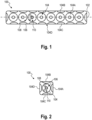
- Fig. 1 shows an exemplary rod 100 that may be used to build a truss structure for a vehicle 10 (see e.g. Fig. 10 ). Accordingly, the rod 100 serve or may be configured as a truss rod, or the like.
- the rod 100 comprises an elongated body.
- Fig. 1 indicates a longitudinal axis 102 of the rod 100 and/or its body.
- a plurality of attachment sockets 104 is formed on and distributed over an outer side of the body.
- the plurality of attachment sockets 102 comprises at least a first number of attachment sockets 104A facing in a first outward direction and a second number of attachment sockets 104B facing in a second outward direction different from the first direction.
- the rod 100 according to Fig. 1 comprises a total of four numbers of attachment sockets 104A, 104B, 104C and 104D, each of which faces in a direction different to the others.
- the numbers of attachment sockets are not limited herein but may depend on e.g. a cross-section of the rod, so that the respective number of attachment sockets may be formed on only two outer surfaces or circumferential sections of the rod 100 and/or its body.
- the plurality of attachment sockets 104 faces perpendicularly away from the longitudinal axis 102. Since the numbers of attachment sockets 104A, 104B, 104C, 104D face in different directions, they may be docked by a component to be attached to the rod 100 from different directions.
- attachment sockets 104 may be configured to attach thereto any component, connector, further rod, or the like.
- the configuration, such as a form and/or shape, of the plurality of attachment sockets 104 may be standardized, may be identical across the plurality of attachment sockets 104, or may be different across the plurality of attachment sockets 104. It is also conceivable that the first number of attachment sockets 104A has a first configuration and the second number has second configuration different to the first configuration, etc.
- Each of the plurality of attachment sockets 104 each comprises a cavity 106 open to the outer side of the body and comprising at least one bearing surface 108.
- the cavity 106 may be configured to at least partially receive the component to be attached, which may have a corresponding plug or the like to dock at the respective attachment socket.
- the bearing surface 108 may be configured to support the component to be attached when received in the respective attachment socket and/or in its cavity 106.
- the plurality of attachment sockets is formed in a grid pattern.
- the first number of attachment sockets 104A and/or the second number of attachment sockets 104B comprises multiple attachment sockets arranged in a row.
- the respective rows extend along the longitudinal axis 102.
- the first number of attachment sockets 104A and the second number of attachment sockets 104B are opposite to each other and/or oriented in directions facing away from each other.
- the first number, second number, third number, and fourth number of attachment sockets 104A-104D are opposite each other pairwise.
- numbers of attachment sockets opposing each other may be in a one-to-one correspondence.
- numbers of attachment sockets 104 opposing each other may be connected to each other at their respective body sections. In other words, opposing attachment sockets 104 may be coupled to each other.
- At least one longitudinal end faces of the rod 100 and/or its body may comprise an attachment socket of the plurality of attachment sockets 104.
- both longitudinal end faces of the rod 100 comprise a respective attachment socket.
- the attachment socket formed at the longitudinal end face may be configured different to the numbers of attachment sockets formed at the lateral surface or circumference of the rod 100, or may be identical thereto.
- At least one of the plurality of attachment sockets 104 may comprise at least one coupling interface 110 arranged in the respective attachment socket 104.
- the at least one coupling interface 110 may be configured to couple any component docked and/or attached to the respective attachment socket 104 to the rod 100.
- the at least one coupling interface 110 may be configured in many ways. For example, it may be formed by one or more coupling openings (as indicated in Fig. 1 by circles in dashed lines) configured to be engaged by a locking-pin or the like of a component to be attached.
- the at least one coupling interface 110 may be configured as a form-fit connection, a bushing, a threaded insert, nut or the like, a rotary nut, a feedthrough, or the like (as indicated in Fig. 1 by a rectangle in dashed lines).
- the at least one coupling interface 110 may be standardized across the entire plurality of attachment sockets 104, or different coupling interfaces may be provided to different attachment sockets of the plurality of attachment sockets 104.
- the at least one coupling interface may be configured as a fastening interface, an electrical interface, and/or feedthrough.
- the at least one coupling interface may be configured as a coupling opening, a clamp, a thread, a screw element, a form-fit part, a snap-fit part, a bushing, a rotary nut, or the like, configured to fasten a component to be attached to the rod 100.
- the respective attachment socket 104 may serve as a kind of power socket, network socket, or the like.
- a component to be attached to it may have a correspondingly configured counter interface.
- a cable for connecting the electrical interface may be guided inside the rod.
- a fluid line, cable, or the like, for example, may be passed through or connected to the feedthrough.
- the rod 100 and/or its body may be a press formed part at which the plurality of attachment sockets 104 is integrally formed.
- it may be a deep drawn part, a thermoformed part, or a compression molding part. These manufacturing processes require only simple tools and little work and/or material.
- the rod, and particularly its body may be formed from at least one layer that is formed by any suitable forming process. The at least one layer may be bent and/or wrapped to the body. Ends of the at least one layer, or ends of multiple layers may then be coupled to each other, for example, by welding, riveting, screwing, or the like.
- the body may be closed or at least partially open. Opposing attachment sockets 104 may be coupled to each other at their respective body sections.
- the rod 100 and/or its body may be solid.
- the plurality of attachment sockets 104 may be formed by a machining process.
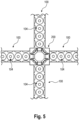
- Fig. 2 shows the rod 100 of Fig. 1 in a side view.
- the rod 100 and/or its body has an angular cross-section, e.g. a rectangular cross-section.
- at least one of the longitudinal end faces, which emerges here from the sheet plane, may comprise an attachment socket 104.
- Fig. 3 and Fig. 4 illustrate another example of the rod 100. This is at least substantially the same as described above. Deviating from the above, here the plurality of attachment sockets 104 is formed convex, while in the exemplary embodiment according to Fig. 1 and Fig. 2 they are formed concave. Otherwise, the above description applies, which does not need to be repeated here.
- the rod 100 may also have a round cross-section.
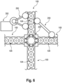
- Fig. 5 illustrates a system for building a truss structure comprising the rod 100.
- Fig. 5 illustrates a possible application scenario of the rod 100, where it is used to build a truss structure.
- the system and/or truss structure comprises a connector 200 configured to couple two or more rods 100 together.
- Fig. 5 shows a node of the truss structure in which a total of four rods 100 are connected to each other via the connector 200.
- the connector 200 may be configured to be attached to at least one attachment socket of the plurality of attachment sockets 104 of the respective rod 100.
- a respective longitudinal end of the rods 100 is coupled to the connector 200.
- the connector 200 may have any configuration suitable for this purpose.
- the connector 200 may comprise a corresponding plug, interface, or the like, configured to be docked and/or attached to the plurality of attachment sockets 104 of the respective rod 100.
- EP 4 187 110 A1 mentioned in the introduction, which is hereby incorporated by reference in its entirety.
- This exemplary connector describes an articulated connector comprising an outer cage, at least two first connecting rods each having a first socket at one end, and a sliding means.
- the outer cage has a plurality of first openings lying in a first common plane and configured to pass the first connecting rods outwardly from an inner side of the outer cage.
- the first openings are dimensioned such that the first sockets each have a first outer surface in flush surface contact with a first inner edge surface of one of the first openings, wherein the sliding means is adapted to make flush surface contact with first inner surfaces of the first sockets such that the flush surface contacts are maintained with the first inner edge surfaces.
- a plurality of attachment options for other components are available through the plurality of attachment sockets 104.
- the plurality of attachment sockets 104 of each rod 100 may be used to attach and/or fasten another component to the respective rod 100, and/or may be used as an electric power socket, a network and/or data socket (if the respective attachment socket 104 is correspondingly connected), etc.
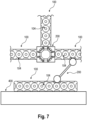
- Fig. 6 illustrates another example of the system for building a truss structure comprising the rod 100. Basically, Fig. 6 illustrates another possible application scenario of the rod 100, where it is used to build a truss structure.
- the system comprises further possible configurations of the connector 200.
- the connector 200 may alternatively or additionally configured to couple a component 300 to the respective rod 100 via at least one attachment socket 104 of the respective rod 100.
- Such configuration of the connector 200 may be referred to as lateral connector.
- the connector 200 may be configured, e.g. may have a respective counter coupling interface or the like, to be fastened to the respective rod 100 when docked to the respective at least one attachment socket 104.
- a coupling interface e.g. the above coupling interface 110, may be of the form-fit and/or force-fit type, snap-fit, screw-fit, clamp-fit, or other suitable connection type.
- the component 300 to be attached to the truss structure and/or the respective rod 100 may be a cabin component, such as an overhead stowage compartment, or the like. This is not limited herein.
- the connector 200 may alternatively or additionally configured to reinforce the truss structure by coupling tow rods 100 together via an angle or corner.
- Such configuration of the connector 200 may be referred to as lateral connector.
- the connector 200 on the right side may reinforce the truss structure to attach the component and/or system 300 thereto. Based on this example, the system allows many different combinations of rods 100 and one or more connectors 200 as well as components and/or systems 300.
- Fig. 7 illustrates another example of the system for building a truss structure comprising the rod 100. Basically, Fig. 7 illustrates another possible application scenario of the rod 100, where it is used to build a truss structure.
- the truss structure, and/or any rod 100 thereof may be coupled, e.g. attached and/or fastened, to a supporting structure 400, such as a cabin monument, or the like, via the connector 200.
- a supporting structure 400 such as a cabin monument, or the like
- the system allows many different combinations of rods 100 and one or more connectors 200 as well as supporting structures 400.
- Fig. 8 illustrates another example of the system for building a truss structure comprising the rod 100. Basically, Fig. 8 illustrates another possible application scenario of the rod 100, where it is used to build a truss structure.
- the truss structure built by using the rod 100 is used to carry a floor 500 of the vehicle.
- the floor 500 may comprise a panel configured in correspondence to the rod 100.
- the panel may comprise a first layer and a second layer coupled to each other.
- a plurality of attachment sockets may be formed in a two-dimensional grid pattern in at least one of the first layer and the second layer.
- Each of the plurality of attachment sockets may comprise a cavity open to an outer side of the respective layer and extending into a space between the first layer and the second layer.
- the cavity comprises at least one bearing surface.
- the floor 500, particularly a respective panel thereof may be configured compatible to the rod 100, e.g. having corresponding attachment sockets, etc. Accordingly, the floor 500 and/or its panel may be coupled to the rod 100 via the at least one connector 200 or any other suitable means.
- a respective one of the rods 100 may be used to attach thereto another equipment or system 600 of the vehicle 10, such as any ATA system.
- the rod 100 may be used to attach thereto an ATA-21 system or the like.
- Fig. 9 illustrates another example of the system for building a truss structure comprising the rod 100.
- Fig. 8 illustrates another possible application scenario of the rod 100, where it is used to build a truss structure.
- the rod 100 may comprise an internal air passage, an internal conduit passage, and/or an internal cable passage, designated in Fig. 9 by reference sign 112.
- Fig. 9 illustrates a correspondingly configured coupling section 600, using the example of an air duct structure of an air conditioning system.
- the rod 100 may be used for guiding and/or delivering air.
- an exemplary air flow is indicated with dashed arrows.
- Fig. 10 illustrates an exemplary configuration of the rod 100.
- the rod 100 may be a press formed part comprising at least one layer, wherein Fig. 10 exemplarily illustrates a first layer 114 and a second layer 116.
- the plurality of attachment sockets 104 may be integrally formed.
- the at least one layer may then be bent or wrapped into the rod-shape to form the rod 100. Ends of the at least one layer bent or wrapped into the rod-shape may then be coupled to each other, e.g. by welding, riveting, screwing, or the like.
- Fig. 10 illustrates an exemplary configuration of the rod 100.
- the rod 100 may be a press formed part comprising at least one layer, wherein Fig. 10 exemplarily illustrates a first layer 114 and a second layer 116.
- the plurality of attachment sockets 104 may be integrally formed.
- the at least one layer may then be bent or wrapped into the rod-shape to form the rod 100. Ends of the
- bottom sections of two opposing cavities 106 may be coupled to each other. Further, in at least some embodiments, the at least one coupling interface 110 may be arranged to be accessible via each one of two opposing cavities 106, thereby connecting the two opposing cavities 106 with each other. It is noted that the above-mentioned floor 500 and/or its panel may have a similar or the same configuration as illustrated in Fig. 10 .
- the respective cavities 106 may also be referred to as a core of the rod 100, since the cavities 106 may provide bending stiffness to the rod 100.
- the cavities 106 have an at least substantially spherical shape, they may also be referred to as bubble core.
- the cavities 106 are exemplarily illustrated to have an at least substantially spherical shape, the cavities 106 may also have an angular shape.
- Fig. 11 illustrates an aircraft as an exemplary vehicle 10 having installed the rod 100 described herein.
- the rod 100 may be used in the vehicle 10, for building a truss structure.
Landscapes
- Engineering & Computer Science (AREA)
- Aviation & Aerospace Engineering (AREA)
- Mechanical Engineering (AREA)
- General Engineering & Computer Science (AREA)
- Mutual Connection Of Rods And Tubes (AREA)
Abstract
Description
- The present invention relates to a rod for a truss structure of a vehicle. Further, the present invention relates to a system for building a truss structure of a vehicle comprising such rod. In addition, the present invention relates to a vehicle comprising such rod and/or system.
- Various fasteners, connectors and attachments may be used to connect components in vehicles. Their configuration and/or design may depend on the nature, size, weight, and installation position of the installation elements concerned. For example, in a vehicle compartment or cabin, truss-like frame structures may be used to attach a component to a ceiling or a side part of the vehicle.
- For example, document
EP 4 187 110 A1 describes a truss structure for an interior of a vehicle, comprising at least one articulated connector and a plurality of components in the form of truss rods arranged on the at least one articulated connector for forming the truss structure. Although this may be used to build a truss structure, it is desirable to provide more flexibility when building a truss structure. - It is therefore an object of the present invention to provide a flexible way of building a truss structure for a vehicle.
- This object is solved by the subject-matter of the appended independent claims. Further embodiments are defined in the appended dependent claims.
- According to a first aspect, there is provided a rod for a truss structure of a vehicle. The rod comprises an elongated body having a plurality of attachment sockets formed on and distributed over an outer side of the body. The plurality of attachment sockets comprises at least a first number of attachment sockets facing in a first direction and a second number of attachment sockets facing in a second direction different from the first direction. Further, each of the plurality of attachment sockets comprises a cavity open to the outer side of the body and comprising at least one bearing surface.
- The proposed rod may serve or may be configured as a truss rod having integrated a plurality of attachment options in the form of the plurality of attachment sockets. It may therefore serve both as a truss rod and for attaching and/or connecting other components. This makes the rod multifunctional. Regardless of where the rod is installed, it provides the plurality of attachment sockets on its outer side for attaching another component, connecting to another rod to form a truss structure, etc., so that a suitable attachment to the same may be identified in virtually any installation position of the rod. This allows an especially flexible truss structure and/or truss structure-like attachment of components, counter elements, counter structure, or the like in a vehicle. Also, this allows high flexibility in the arrangement of components of the vehicle.
- For example, the plurality of attachment sockets may be distributed along the elongated extension of the rod and/or body, i.e. along its longitudinal axis. Further, the plurality of attachment sockets may be distributed around the circumference, the peripheral surface, and/or over the outer surfaces of the rod and/or body. The directions in which the attachment sockets, in particular the first number of attachment sockets and/or the second number of attachment sockets, face may be related or referred to the longitudinal axis of the rod and/or body. Accordingly, the first direction and the second direction may extend at least substantially perpendicularly away from the longitudinal axis of the rod. Attachment sockets facing different directions may accordingly be docked from different directions and/or angles by a component, further rod, etc. to be attached to them. The attachment sockets from the first number of attachment sockets may be arranged at least substantially opposite or adjacent to the attachment sockets from the second number of attachment sockets. There may also be more than two numbers of attachment sockets. For example, if the rod has an angular cross-section, causing the body to have four lateral and two end surfaces, attachment sockets may also be formed on more or all of the outer surfaces, respectively. The number of attachment sockets may be greater than or equal to one, wherein multiple attachments sockets provide correspondingly more attachment options in different directions of the rod.
- The respective cavity of the plurality of attachment sockets may have different cross-sections and/or body shapes. For example, these may be at least substantially round, at least substantially spherical, angular, polygonal, or the like. A wide range of cross-sections and/or body shapes are possible, if they are suitable for forming a stable core of the panel, which may be determined, for example, by calculation, modeling, simulation, testing, or the like. Merely by way of example, the cavity may have an at least substantially and/or partial spherical form or shape, thereby forming a bubble core. In another example, the cavity may have a polygonal form or shape, e.g. a truncated pyramid or the like, thereby forming a rectangular core. In at least some embodiments, the respective cavity of the plurality of attachment sockets may open to the interior of the vehicle, and may be configured, particularly by its at least one bearing surface, to at least partially receive and/or support another component, a further rod, or the like. The respective attachment socket may be configured to provide a form-fit with the component, rod, system, connector, etc. attached to it.
- According to an embodiment, the plurality of attachment sockets may be formed in a grid pattern. For example, an unwinding of the body and/or its shell surface may be considered, on which the plurality of attachment sockets may be formed in the grid pattern. If the rod is installed in a truss structure, it provides a plurality of attachment sockets arranged in a grid pattern. This further facilitates the attachment of components, further rods, connectors, etc. to the rod.
- In an embodiment, the first number of attachment sockets and/or the second number of attachment sockets may comprise multiple attachment sockets arranged in a row. For example, the respective attachment sockets may be arranged in a respective row, wherein the row extends along the elongated extension of the rod and/or the body, i.e. along its longitudinal axis. The first number of attachment sockets may form a first row extending along the elongated extension. Likewise, the second number of attachment sockets may form a second row extending along the elongated extension. The first and second row of attachment sockets may be formed on different outer surfaces of the rod and/or body and in different circumferential sections of the rod and/or body. It is also conceivable that the body has, for example, a rectangular cross-section with four lateral outer surfaces, and a corresponding number of attachment sockets and/or rows are formed on each of the lateral outer surfaces, i.e. a total of four rows of attachment sockets each facing in different directions.
- According to an embodiment, the first number of attachment sockets and the second number of attachment sockets are opposite to each other and/or oriented in directions facing away from each other. Thus, the rod may provide attachment options in mutually opposite directions.
- In an embodiment, the body may have a round or circular cross-section, and the plurality of attachment sockets are formed over a circumferential surface at different circumferential positions and/or in different circumferential sections. This may provide a round rod with attachment options arranged circumferentially.
- According to an embodiment wherein the body has an angular cross-section, and the plurality of attachment sockets are formed on different outer surfaces facing different directions. For example, the rod and/or body may have a rectangular cross-section, resulting in four lateral outer surfaces. A respective number of attachment sockets may be formed on at least two, or three, or all of the lateral outer surfaces. This may provide a round rod with attachment options arranged circumferentially.
- In an embodiment, an attachment socket of the plurality of attachment sockets may be formed on at least one of longitudinal end faces of the rod and/or body. Thus, also in addition to attachment sockets arranged on the circumferential side, at least one attachment socket may also be formed at each of the longitudinal ends and/or end faces of the rod and/or body. When building a truss structure, two or more rods and/or one or more rods and a connector may be attached to each other lengthwise. For example, T-junctions or the like may be built.
- According to an embodiment, at least one of the plurality of attachment sockets may comprise at least one coupling interface arranged in the respective attachment socket. The at least one coupling interface may be configured to couple any component docked and/or attached to the respective attachment socket to the rod. The at least one coupling interface may be configured in many ways. For example, it may be formed by one or more coupling openings configured to be engaged by a locking-pin of a component to be attached. Alternatively or additionally, the at least one coupling interface may be configured as a form-fit connection, a bushing, a threaded insert, nut or the like, a rotary nut, a feedthrough, or the like. The at least one coupling interface may be standardized across the entire plurality of attachment sockets, or different coupling interfaces may be provided to different attachment sockets.
- In an embodiment, the at least one coupling interface may be configured as a fastening interface, an electrical interface, and/or feedthrough. For example, in case of a fastening interface, the at least one coupling interface may be configured as a coupling opening, a clamp, a thread, a screw element, a form-fit part, a snap-fit part, a bushing, a rotary nut, or the like. Further, in case of an electrical interface, the respective attachment socket may serve as a kind of power socket, network socket, or the like. A component to be attached to it may have a correspondingly configured counter interface. A cable for connecting the electrical interface may be guided inside the rod. A fluid line, cable, or the like, for example, may be passed through or connected to the feedthrough.
- According to an embodiment, the body may be a press formed part at which the plurality of attachment sockets is integrally formed. For example, it may be a deep drawn part, a thermoformed part, or a compression molding part. These manufacturing processes require only simple tools and little work and/or material. By way of example, the rod, and particularly its body, may be formed from at least one layer that is formed by any suitable forming process. The at least one layer may be bent and/or wrapped to the body. Ends of the at least one layer, or ends of multiple layers may then be coupled to each other, for example, by welding, riveting, screwing, or the like. The body may be closed or at least partially open. Opposing attachment sockets may be coupled to each other at their respective body sections.
- Alternatively, the rod, and particularly its body, may be solid. In this case, the plurality of attachment sockets may be formed by a machining process. Or there may be a solid core with at least one layer wrapped around it and coupled to it.
- In an embodiment, the rod may comprise an internal air passage, an internal conduit passage, and/or an internal cable passage. In other words, the rod may additionally be used for guiding air, e.g. of a climate system of the vehicle, as support for an electric cable and/or a data cable, etc.
- According to a second aspect, there is provided a system for a truss structure of a vehicle. The system comprises at least one rod according to the first aspect. Further, the system comprises at least one connector configured to be attached and/or coupled, e.g. attached and/or fastened, to at least one attachment socket of the plurality of attachment sockets of the rod.
- The proposed system allows to build a flexible and freely configurable truss structure. Multiple rods may be coupled and/or connected to each other in the manner of a truss structure. The truss structure built up in this way may be easily attached, reinforced or generally offers a plurality of attachment options due to the plurality of attachment sockets formed on the respective rod. The at least one connector may be configured for any type of node of the truss structure.
- According to an embodiment, the at least one connector may comprise an end face connector configured to couple the at least one rod to at least one further rod via respective longitudinal end faces of the rods. This allows to build a multi-node.
- In an embodiment, the at least one connector comprises a lateral connector configured to couple the at least one rod to at least one further rod via respective outer sides of the rods. This allows another component, another rod, or the like to be attached to the respective rod from the lateral direction. For example, this may also be used to form reinforcements.
- According to a third aspect, there is provided a vehicle comprising at least one rod according to the first aspect, and/or comprising a system according to the second aspect. The at least one rod is installed in an interior of the vehicle.
- For example, the vehicle may be any kind of vehicle, such as a rail vehicle, an aircraft, spacecraft, a motor vehicle, or the like. The rod may be used to build a truss structure in the interior of the vehicle.
- The invention will be explained in greater detail with reference to exemplary embodiments depicted in the drawings as appended.
- The present invention is explained in more detail below with reference to the embodiments shown in the schematic figures:
- Fig. 1
- illustrates in a top view an exemplary rod for a truss structure of a vehicle according to an embodiment.
- Fig. 2
- illustrates the rod of
Fig. 1 in a side view. - Fig. 3
- illustrates in a top view an exemplary rod for a truss structure of a vehicle according to an embodiment.
- Fig. 4
- illustrates the rod of
Fig. 3 in a side view. - Fig. 5
- illustrates a system comprising multiple rods and a connector according to an embodiment, forming a truss structure.
- Fig. 6
- illustrates a system comprising multiple rods and multiple connectors according to an embodiment, forming a truss structure.
- Fig. 7
- illustrates a system comprising multiple rods and multiple connectors according to an embodiment, forming a truss structure.
- Fig. 8
- illustrates a system comprising multiple rods and multiple connectors according to an embodiment, forming a truss structure.
- Fig. 9
- illustrates a system comprising multiple rods and multiple connectors according to an embodiment, forming a truss structure.
- Fig. 10
- illustrates an exemplary configuration of a rod according to an embodiment.
- Fig. 11
- illustrates an aircraft as an exemplary vehicle having installed a rod according to an embodiment.
- In the figures of the drawing, elements, features and components which are identical, functionally identical and of identical action are denoted in each case by the same reference designations unless stated otherwise.
-
Fig. 1 shows anexemplary rod 100 that may be used to build a truss structure for a vehicle 10 (see e.g.Fig. 10 ). Accordingly, therod 100 serve or may be configured as a truss rod, or the like. - The
rod 100 comprises an elongated body.Fig. 1 indicates alongitudinal axis 102 of therod 100 and/or its body. A plurality ofattachment sockets 104 is formed on and distributed over an outer side of the body. The plurality ofattachment sockets 102 comprises at least a first number ofattachment sockets 104A facing in a first outward direction and a second number ofattachment sockets 104B facing in a second outward direction different from the first direction. Merely by way of example, therod 100 according toFig. 1 comprises a total of four numbers ofattachment sockets rod 100 and/or its body. Referring toFig. 1 , the plurality ofattachment sockets 104 faces perpendicularly away from thelongitudinal axis 102. Since the numbers ofattachment sockets rod 100 from different directions. For example,attachment sockets 104 may be configured to attach thereto any component, connector, further rod, or the like. The configuration, such as a form and/or shape, of the plurality ofattachment sockets 104 may be standardized, may be identical across the plurality ofattachment sockets 104, or may be different across the plurality ofattachment sockets 104. It is also conceivable that the first number ofattachment sockets 104A has a first configuration and the second number has second configuration different to the first configuration, etc. Each of the plurality ofattachment sockets 104 each comprises acavity 106 open to the outer side of the body and comprising at least onebearing surface 108. Thecavity 106 may be configured to at least partially receive the component to be attached, which may have a corresponding plug or the like to dock at the respective attachment socket. The bearingsurface 108 may be configured to support the component to be attached when received in the respective attachment socket and/or in itscavity 106. - Considering an unwinding of the
rod 100 and/or its body according toFig. 1 , it is understood that the plurality of attachment sockets is formed in a grid pattern. Further, as can be seen fromFig. 1 , the first number ofattachment sockets 104A and/or the second number ofattachment sockets 104B comprises multiple attachment sockets arranged in a row. InFig. 1 , the respective rows extend along thelongitudinal axis 102. Also, the first number ofattachment sockets 104A and the second number ofattachment sockets 104B are opposite to each other and/or oriented in directions facing away from each other. In this exemplary embodiment, the first number, second number, third number, and fourth number ofattachment sockets 104A-104D are opposite each other pairwise. Optionally, numbers of attachment sockets opposing each other may be in a one-to-one correspondence. Further, numbers ofattachment sockets 104 opposing each other may be connected to each other at their respective body sections. In other words, opposingattachment sockets 104 may be coupled to each other. - In at least some embodiments, at least one longitudinal end faces of the
rod 100 and/or its body may comprise an attachment socket of the plurality ofattachment sockets 104. In the exemplary embodiment illustrated inFig. 1 , both longitudinal end faces of therod 100 comprise a respective attachment socket. It is noted that the attachment socket formed at the longitudinal end face may be configured different to the numbers of attachment sockets formed at the lateral surface or circumference of therod 100, or may be identical thereto. - In at least some embodiments, at least one of the plurality of
attachment sockets 104 may comprise at least onecoupling interface 110 arranged in therespective attachment socket 104. The at least onecoupling interface 110 may be configured to couple any component docked and/or attached to therespective attachment socket 104 to therod 100. The at least onecoupling interface 110 may be configured in many ways. For example, it may be formed by one or more coupling openings (as indicated inFig. 1 by circles in dashed lines) configured to be engaged by a locking-pin or the like of a component to be attached. Alternatively or additionally, the at least onecoupling interface 110 may be configured as a form-fit connection, a bushing, a threaded insert, nut or the like, a rotary nut, a feedthrough, or the like (as indicated inFig. 1 by a rectangle in dashed lines). The at least onecoupling interface 110 may be standardized across the entire plurality ofattachment sockets 104, or different coupling interfaces may be provided to different attachment sockets of the plurality ofattachment sockets 104. In at least some embodiments, the at least one coupling interface may be configured as a fastening interface, an electrical interface, and/or feedthrough. For example, in case of a fastening interface, the at least one coupling interface may be configured as a coupling opening, a clamp, a thread, a screw element, a form-fit part, a snap-fit part, a bushing, a rotary nut, or the like, configured to fasten a component to be attached to therod 100. Further, in case of an electrical interface, therespective attachment socket 104 may serve as a kind of power socket, network socket, or the like. A component to be attached to it may have a correspondingly configured counter interface. A cable for connecting the electrical interface may be guided inside the rod. A fluid line, cable, or the like, for example, may be passed through or connected to the feedthrough. - For example, the
rod 100 and/or its body may be a press formed part at which the plurality ofattachment sockets 104 is integrally formed. For example, it may be a deep drawn part, a thermoformed part, or a compression molding part. These manufacturing processes require only simple tools and little work and/or material. By way of example, the rod, and particularly its body, may be formed from at least one layer that is formed by any suitable forming process. The at least one layer may be bent and/or wrapped to the body. Ends of the at least one layer, or ends of multiple layers may then be coupled to each other, for example, by welding, riveting, screwing, or the like. The body may be closed or at least partially open. Opposingattachment sockets 104 may be coupled to each other at their respective body sections. - Alternatively, the
rod 100 and/or its body, may be solid. In this case, the plurality ofattachment sockets 104 may be formed by a machining process. Or there may be a solid core with at least one layer wrapped around it and coupled to it. -
Fig. 2 shows therod 100 ofFig. 1 in a side view. In this exemplary embodiment, therod 100 and/or its body has an angular cross-section, e.g. a rectangular cross-section. As mentioned above, at least one of the longitudinal end faces, which emerges here from the sheet plane, may comprise anattachment socket 104. -
Fig. 3 and Fig. 4 illustrate another example of therod 100. This is at least substantially the same as described above. Deviating from the above, here the plurality ofattachment sockets 104 is formed convex, while in the exemplary embodiment according toFig. 1 and Fig. 2 they are formed concave. Otherwise, the above description applies, which does not need to be repeated here. - It is noted that although the above examples of the
rod 100 have an angular cross-section, therod 100 may also have a round cross-section. -
Fig. 5 illustrates a system for building a truss structure comprising therod 100. Basically,Fig. 5 illustrates a possible application scenario of therod 100, where it is used to build a truss structure. - Besides the
rod 100, the system and/or truss structure comprises aconnector 200 configured to couple two ormore rods 100 together. Merely by way of example,Fig. 5 shows a node of the truss structure in which a total of fourrods 100 are connected to each other via theconnector 200. Theconnector 200 may be configured to be attached to at least one attachment socket of the plurality ofattachment sockets 104 of therespective rod 100. In this example, a respective longitudinal end of therods 100 is coupled to theconnector 200. - The
connector 200 may have any configuration suitable for this purpose. For example, theconnector 200 may comprise a corresponding plug, interface, or the like, configured to be docked and/or attached to the plurality ofattachment sockets 104 of therespective rod 100. Merely by way of example, reference is made to the European patent applicationEP 4 187 110 A1 mentioned in the introduction, which is hereby incorporated by reference in its entirety. This exemplary connector describes an articulated connector comprising an outer cage, at least two first connecting rods each having a first socket at one end, and a sliding means. The outer cage has a plurality of first openings lying in a first common plane and configured to pass the first connecting rods outwardly from an inner side of the outer cage. The first openings are dimensioned such that the first sockets each have a first outer surface in flush surface contact with a first inner edge surface of one of the first openings, wherein the sliding means is adapted to make flush surface contact with first inner surfaces of the first sockets such that the flush surface contacts are maintained with the first inner edge surfaces. - With reference to
Fig. 5 , it can be understood that in the truss structure formed in this way, a plurality of attachment options for other components, optionally alsofurther rods 100, are available through the plurality ofattachment sockets 104. As described herein, the plurality ofattachment sockets 104 of eachrod 100 may be used to attach and/or fasten another component to therespective rod 100, and/or may be used as an electric power socket, a network and/or data socket (if therespective attachment socket 104 is correspondingly connected), etc. -
Fig. 6 illustrates another example of the system for building a truss structure comprising therod 100. Basically,Fig. 6 illustrates another possible application scenario of therod 100, where it is used to build a truss structure. - Deviating from the above, the system comprises further possible configurations of the
connector 200. As exemplarily illustrated inFig. 6 , theconnector 200 may alternatively or additionally configured to couple acomponent 300 to therespective rod 100 via at least oneattachment socket 104 of therespective rod 100. Such configuration of theconnector 200 may be referred to as lateral connector. For example, theconnector 200 may be configured, e.g. may have a respective counter coupling interface or the like, to be fastened to therespective rod 100 when docked to the respective at least oneattachment socket 104. As described herein, such a coupling interface, e.g. theabove coupling interface 110, may be of the form-fit and/or force-fit type, snap-fit, screw-fit, clamp-fit, or other suitable connection type. - Merely by way of example, the
component 300 to be attached to the truss structure and/or therespective rod 100 may be a cabin component, such as an overhead stowage compartment, or the like. This is not limited herein. - Further, as exemplarily illustrated in
Fig. 6 , theconnector 200 may alternatively or additionally configured to reinforce the truss structure by couplingtow rods 100 together via an angle or corner. Such configuration of theconnector 200 may be referred to as lateral connector. In the illustrated example, theconnector 200 on the right side may reinforce the truss structure to attach the component and/orsystem 300 thereto. Based on this example, the system allows many different combinations ofrods 100 and one ormore connectors 200 as well as components and/orsystems 300. -
Fig. 7 illustrates another example of the system for building a truss structure comprising therod 100. Basically,Fig. 7 illustrates another possible application scenario of therod 100, where it is used to build a truss structure. - Deviating from the above, the truss structure, and/or any
rod 100 thereof, may be coupled, e.g. attached and/or fastened, to a supportingstructure 400, such as a cabin monument, or the like, via theconnector 200. Based on this example, the system allows many different combinations ofrods 100 and one ormore connectors 200 as well as supportingstructures 400. -
Fig. 8 illustrates another example of the system for building a truss structure comprising therod 100. Basically,Fig. 8 illustrates another possible application scenario of therod 100, where it is used to build a truss structure. - In this example, the truss structure built by using the
rod 100 is used to carry afloor 500 of the vehicle. For example, thefloor 500 may comprise a panel configured in correspondence to therod 100. By way of example, the panel may comprise a first layer and a second layer coupled to each other. A plurality of attachment sockets may be formed in a two-dimensional grid pattern in at least one of the first layer and the second layer. Each of the plurality of attachment sockets may comprise a cavity open to an outer side of the respective layer and extending into a space between the first layer and the second layer. The cavity comprises at least one bearing surface. In other words, thefloor 500, particularly a respective panel thereof, may be configured compatible to therod 100, e.g. having corresponding attachment sockets, etc. Accordingly, thefloor 500 and/or its panel may be coupled to therod 100 via the at least oneconnector 200 or any other suitable means. - Further, by way of example, a respective one of the
rods 100 may be used to attach thereto another equipment orsystem 600 of thevehicle 10, such as any ATA system. For instance, therod 100 may be used to attach thereto an ATA-21 system or the like. -
Fig. 9 illustrates another example of the system for building a truss structure comprising therod 100. Basically,Fig. 8 illustrates another possible application scenario of therod 100, where it is used to build a truss structure. - In this example, the
rod 100 may comprise an internal air passage, an internal conduit passage, and/or an internal cable passage, designated inFig. 9 byreference sign 112.Fig. 9 illustrates a correspondingly configuredcoupling section 600, using the example of an air duct structure of an air conditioning system. Here, therod 100 may be used for guiding and/or delivering air. InFig. 9 , an exemplary air flow is indicated with dashed arrows. -
Fig. 10 illustrates an exemplary configuration of therod 100. Therod 100 may be a press formed part comprising at least one layer, whereinFig. 10 exemplarily illustrates afirst layer 114 and asecond layer 116. In the at least one layer, e.g. in each of thelayers attachment sockets 104 may be integrally formed. The at least one layer may then be bent or wrapped into the rod-shape to form therod 100. Ends of the at least one layer bent or wrapped into the rod-shape may then be coupled to each other, e.g. by welding, riveting, screwing, or the like. Also, as exemplarily indicated inFig. 10 , bottom sections of two opposingcavities 106 may be coupled to each other. Further, in at least some embodiments, the at least onecoupling interface 110 may be arranged to be accessible via each one of two opposingcavities 106, thereby connecting the two opposingcavities 106 with each other. It is noted that the above-mentionedfloor 500 and/or its panel may have a similar or the same configuration as illustrated inFig. 10 . - It is noted that the
respective cavities 106, especially when arranged opposing each other, may also be referred to as a core of therod 100, since thecavities 106 may provide bending stiffness to therod 100. As in this example thecavities 106 have an at least substantially spherical shape, they may also be referred to as bubble core. - Further, it is noted that although the
cavities 106 are exemplarily illustrated to have an at least substantially spherical shape, thecavities 106 may also have an angular shape. -
Fig. 11 illustrates an aircraft as anexemplary vehicle 10 having installed therod 100 described herein. For example, therod 100 may be used in thevehicle 10, for building a truss structure. - In the foregoing detailed description, various features are grouped together in one or more examples or examples with the purpose of streamlining the disclosure. It is to be understood that the above description is intended to be illustrative, and not restrictive. It is intended to cover all alternatives, modifications and equivalents. Many other examples will be apparent to one skilled in the art upon reviewing the above specification. The embodiments were chosen and described in order to best explain the principles of the invention and its practical applications, to thereby enable others skilled in the art to best utilize the invention and various embodiments with various modifications as are suited to the particular use contemplated.
-
- 10
- vehicle (e.g. aircraft)
- 100
- rod
- 102
- longitudinal axis
- 104
- attachment socket(s)
- 104A
- (number of) attachment socket(s)
- 104B
- (number of) attachment socket(s)
- 104C
- (number of) attachment socket(s)
- 104D
- (number of) attachment socket(s)
- 106
- cavity
- 108
- bearing surface
- 110
- coupling interface
- 112
- (internal) passage
- 114
- first layer
- 116
- second layer
- 200
- connector
- 300
- component and/or system
- 400
- supporting structure
- 500
- floor (e.g. panel)
- 600
- equipment and/or system
Claims (15)
- A rod (100) for a truss structure of a vehicle (10), the rod (100) comprising an elongated body having a plurality of attachment sockets (104) formed on and distributed over an outer side of the body, the plurality of attachment sockets (104) comprising at least a first number of attachment sockets (104A, 104B, 104C, 104D) facing in a first direction and a second number of attachment sockets (104A, 104B, 104C, 104D) facing in a second direction different from the first direction, and the plurality of attachment sockets (104) each comprising a cavity (106) open to the outer side of the body and comprising at least one bearing surface (108).
- The rod of claim 1, wherein the plurality of attachment sockets (104) is formed in a grid pattern.
- The rod of claim 1 or 2, wherein the first number of attachment sockets (104A, 104B, 104C, 104D) and/or the second number of attachment sockets (104A, 104B, 104C, 104D) comprises multiple attachment sockets arranged in a row.
- The rod of any one of the preceding claims, wherein the first number of attachment sockets (104A, 104B, 104C, 104D) and the second number of attachment sockets (104A, 104B, 104C, 104D) are arranged opposite to each other and/or oriented in directions facing away from each other.
- The rod of any one of the preceding claims, wherein the body has a round or circular cross-section, and the plurality of attachment sockets (104) are formed over a circumferential surface at different circumferential positions.
- The rod of any one of claims 1 to 4, wherein the body has an angular cross-section, and the plurality of attachment sockets (104) are formed on different outer surfaces facing different directions.
- The rod of any one of the preceding claims, wherein at least one attachment socket of the plurality of attachment sockets (104) is formed on at least one of longitudinal end faces of the body.
- The rod of any one of the preceding claims, wherein at least one of the plurality of attachment sockets (104) comprises at least one coupling interface (110) arranged in the respective attachment socket.
- The rod of claim 8, wherein at least one coupling interface (110) is configured as a fastening interface, an electrical interface, and/or feedthrough.
- The rod of any one of the preceding claims, wherein the body is a press formed part at which the plurality of attachment sockets (104) is integrally formed.
- The rod of any one of the preceding claims, wherein the rod (100) comprises an internal air passage, an internal conduit passage, and/or an internal cable passage (112).
- A system for a truss structure of a vehicle, comprising:at least one rod (100) according to any one of the preceding claims; andat least one connector (200) configured to be attached to at least one attachment socket of the plurality of attachment sockets (104) of the rod (100).
- The system of claim 12, wherein the at least one connector (200) comprises an end face connector configured to couple the at least one rod (100) to at least one further rod (100) via respective longitudinal end faces of the rods.
- The system of claim 12 or 13, wherein the at least one connector (200) comprises a lateral connector configured to couple the at least one rod (100) to at least one further rod (100) via respective outer sides of the rods.
- A vehicle, comprising at least one panel according to any one of claims 1 to 11, and/or comprising a system according to any one of claims 12 to 14, installed in an interior of the vehicle (10).
Priority Applications (3)
| Application Number | Priority Date | Filing Date | Title |
|---|---|---|---|
| EP23179263.1A EP4477895B1 (en) | 2023-06-14 | 2023-06-14 | Rod with attachment sockets for a truss structure of a vehicle |
| US18/734,317 US20240417055A1 (en) | 2023-06-14 | 2024-06-05 | Rod with attachment sockets for a truss structure of a vehicle |
| CN202410751068.7A CN119142530A (en) | 2023-06-14 | 2024-06-12 | Rods for a truss structure of a vehicle, system for a truss structure of a vehicle and vehicle |
Applications Claiming Priority (1)
| Application Number | Priority Date | Filing Date | Title |
|---|---|---|---|
| EP23179263.1A EP4477895B1 (en) | 2023-06-14 | 2023-06-14 | Rod with attachment sockets for a truss structure of a vehicle |
Publications (2)
| Publication Number | Publication Date |
|---|---|
| EP4477895A1 true EP4477895A1 (en) | 2024-12-18 |
| EP4477895B1 EP4477895B1 (en) | 2026-03-18 |
Family
ID=86851867
Family Applications (1)
| Application Number | Title | Priority Date | Filing Date |
|---|---|---|---|
| EP23179263.1A Active EP4477895B1 (en) | 2023-06-14 | 2023-06-14 | Rod with attachment sockets for a truss structure of a vehicle |
Country Status (3)
| Country | Link |
|---|---|
| US (1) | US20240417055A1 (en) |
| EP (1) | EP4477895B1 (en) |
| CN (1) | CN119142530A (en) |
Citations (1)
| Publication number | Priority date | Publication date | Assignee | Title |
|---|---|---|---|---|
| EP4187110A1 (en) | 2021-11-30 | 2023-05-31 | Airbus Operations GmbH | Joint connector for connecting a plurality of components in a vehicle |
Family Cites Families (10)
| Publication number | Priority date | Publication date | Assignee | Title |
|---|---|---|---|---|
| US1843364A (en) * | 1930-04-09 | 1932-02-02 | Powel Crosley Jr | Aircraft truss support |
| US4806042A (en) * | 1987-11-19 | 1989-02-21 | The Fluorocarbon Company | Quick-disconnect rigid coupling |
| US7028442B2 (en) * | 2001-07-03 | 2006-04-18 | Merrifield Donald V | Deployable truss beam with orthogonally-hinged folding diagonals |
| US7716897B2 (en) * | 2001-07-03 | 2010-05-18 | Merrifield Donald V | Deployable rectangular truss beam with orthogonally-hinged folding diagonals |
| US7891608B2 (en) * | 2007-05-03 | 2011-02-22 | The Boeing Company | Space frame fuselage structure and related methods |
| FR3001088B1 (en) * | 2013-01-11 | 2015-03-06 | Airbus Operations Sas | DEVICE FOR MOUNTING FEED SYSTEMS FOR AIRCRAFT |
| US10329005B2 (en) * | 2016-04-12 | 2019-06-25 | The Boeing Company | Aircraft compression relief rod |
| ES3029238T3 (en) * | 2022-01-26 | 2025-06-23 | Airbus Operations Gmbh | Coupling device for a connecting rod |
| TWM649538U (en) * | 2023-04-25 | 2023-12-21 | 魏仲志 | Universal connecting rod assembly structure |
| EP4484275A1 (en) * | 2023-06-28 | 2025-01-01 | Airbus Operations GmbH | Mounting interface for trusswork |
-
2023
- 2023-06-14 EP EP23179263.1A patent/EP4477895B1/en active Active
-
2024
- 2024-06-05 US US18/734,317 patent/US20240417055A1/en active Pending
- 2024-06-12 CN CN202410751068.7A patent/CN119142530A/en active Pending
Patent Citations (1)
| Publication number | Priority date | Publication date | Assignee | Title |
|---|---|---|---|---|
| EP4187110A1 (en) | 2021-11-30 | 2023-05-31 | Airbus Operations GmbH | Joint connector for connecting a plurality of components in a vehicle |
Also Published As
| Publication number | Publication date |
|---|---|
| CN119142530A (en) | 2024-12-17 |
| EP4477895B1 (en) | 2026-03-18 |
| US20240417055A1 (en) | 2024-12-19 |
Similar Documents
| Publication | Publication Date | Title |
|---|---|---|
| EP2809580B1 (en) | System and method for mounting aircraft system components in the crown area of an aircraft | |
| CN110525688B (en) | On-orbit reconfigurable extensible satellite system | |
| US5979833A (en) | Modular spacecraft architecture | |
| EP2061696B1 (en) | Frame element, aircraft air-conditioning system and method for the installation of a frame element in an aircraft | |
| US8946551B2 (en) | Floor wire harness package assembly and installation methods | |
| EP3098463B1 (en) | Rotary joint, framework construction kit and method for manufacturing a rotary joint | |
| CN109720540B (en) | Aircraft fuselages and modules for absorbing collision energy in the lower cabin of an aircraft for transporting passengers | |
| EP2738434B1 (en) | Zero-moment fitting | |
| US9341386B2 (en) | Vehicular airflow outlet | |
| CN102862673B (en) | Be used for the medial support structures of the driving cabin of airborne vehicle | |
| US11753140B2 (en) | Aircraft fuselage portion comprising movable or detachable under floor struts | |
| EP4477895B1 (en) | Rod with attachment sockets for a truss structure of a vehicle | |
| US20180356007A1 (en) | Snap and stack ring post | |
| CN106364422A (en) | Bracket for fixing wiring harnesses and butt-joint inserting pieces of automobile | |
| EP3266706A1 (en) | Aircraft installation arrangement and installation system for mounting an overhead luggage compartment | |
| US11174969B2 (en) | Threaded connection of a duct | |
| US8070097B2 (en) | Mobile divider for an aircraft | |
| EP3744635B1 (en) | Raceway systems and methods for routing transferring components within an interior cabin of an aircraft | |
| CN217374391U (en) | Via hole rubber part for wire harness | |
| CA2788803A1 (en) | Composite aerospace structure with integrated conveyance element | |
| EP4477490A1 (en) | Panel with attachment sockets for an interior of a vehicle | |
| EP3281860A1 (en) | Aircraft cabin with secondary aircraft cabin structure mounted with rotary joints and method for mounting a secondary aircraft cabin structure in an aircraft cabin | |
| CN223494227U (en) | Automobile air conditioner connector with multiple layers of inner holes | |
| EP3067274B1 (en) | Duct assembly and method of assembling thereof | |
| CN212354411U (en) | UAV equipment compartment and UAV |
Legal Events
| Date | Code | Title | Description |
|---|---|---|---|
| PUAI | Public reference made under article 153(3) epc to a published international application that has entered the european phase |
Free format text: ORIGINAL CODE: 0009012 |
|
| STAA | Information on the status of an ep patent application or granted ep patent |
Free format text: STATUS: THE APPLICATION HAS BEEN PUBLISHED |
|
| AK | Designated contracting states |
Kind code of ref document: A1 Designated state(s): AL AT BE BG CH CY CZ DE DK EE ES FI FR GB GR HR HU IE IS IT LI LT LU LV MC ME MK MT NL NO PL PT RO RS SE SI SK SM TR |
|
| STAA | Information on the status of an ep patent application or granted ep patent |
Free format text: STATUS: REQUEST FOR EXAMINATION WAS MADE |
|
| 17P | Request for examination filed |
Effective date: 20250618 |
|
| GRAP | Despatch of communication of intention to grant a patent |
Free format text: ORIGINAL CODE: EPIDOSNIGR1 |
|
| STAA | Information on the status of an ep patent application or granted ep patent |
Free format text: STATUS: GRANT OF PATENT IS INTENDED |
|
| INTG | Intention to grant announced |
Effective date: 20251024 |
|
| GRAS | Grant fee paid |
Free format text: ORIGINAL CODE: EPIDOSNIGR3 |
|
| GRAA | (expected) grant |
Free format text: ORIGINAL CODE: 0009210 |
|
| STAA | Information on the status of an ep patent application or granted ep patent |
Free format text: STATUS: THE PATENT HAS BEEN GRANTED |
|
| AK | Designated contracting states |
Kind code of ref document: B1 Designated state(s): AL AT BE BG CH CY CZ DE DK EE ES FI FR GB GR HR HU IE IS IT LI LT LU LV MC ME MK MT NL NO PL PT RO RS SE SI SK SM TR |
|
| REG | Reference to a national code |
Ref country code: CH Ref legal event code: F10 Free format text: ST27 STATUS EVENT CODE: U-0-0-F10-F00 (AS PROVIDED BY THE NATIONAL OFFICE) Effective date: 20260318 Ref country code: GB Ref legal event code: FG4D |
|
| REG | Reference to a national code |
Ref country code: DE Ref legal event code: R096 Ref document number: 602023013596 Country of ref document: DE |
|
| REG | Reference to a national code |
Ref country code: IE Ref legal event code: FG4D |