EP4477894A1 - Flow equalizing device and diverting device - Google Patents
Flow equalizing device and diverting device Download PDFInfo
- Publication number
- EP4477894A1 EP4477894A1 EP22923622.9A EP22923622A EP4477894A1 EP 4477894 A1 EP4477894 A1 EP 4477894A1 EP 22923622 A EP22923622 A EP 22923622A EP 4477894 A1 EP4477894 A1 EP 4477894A1
- Authority
- EP
- European Patent Office
- Prior art keywords
- pipeline
- blades
- flow equalizing
- equalizing device
- fluid
- Prior art date
- Legal status (The legal status is an assumption and is not a legal conclusion. Google has not performed a legal analysis and makes no representation as to the accuracy of the status listed.)
- Pending
Links
Images



Classifications
-
- F—MECHANICAL ENGINEERING; LIGHTING; HEATING; WEAPONS; BLASTING
- F15—FLUID-PRESSURE ACTUATORS; HYDRAULICS OR PNEUMATICS IN GENERAL
- F15D—FLUID DYNAMICS, i.e. METHODS OR MEANS FOR INFLUENCING THE FLOW OF GASES OR LIQUIDS
- F15D1/00—Influencing flow of fluids
- F15D1/02—Influencing flow of fluids in pipes or conduits
- F15D1/025—Influencing flow of fluids in pipes or conduits by means of orifice or throttle elements
-
- F—MECHANICAL ENGINEERING; LIGHTING; HEATING; WEAPONS; BLASTING
- F15—FLUID-PRESSURE ACTUATORS; HYDRAULICS OR PNEUMATICS IN GENERAL
- F15D—FLUID DYNAMICS, i.e. METHODS OR MEANS FOR INFLUENCING THE FLOW OF GASES OR LIQUIDS
- F15D1/00—Influencing flow of fluids
- F15D1/0015—Whirl chambers, e.g. vortex valves
-
- F—MECHANICAL ENGINEERING; LIGHTING; HEATING; WEAPONS; BLASTING
- F15—FLUID-PRESSURE ACTUATORS; HYDRAULICS OR PNEUMATICS IN GENERAL
- F15D—FLUID DYNAMICS, i.e. METHODS OR MEANS FOR INFLUENCING THE FLOW OF GASES OR LIQUIDS
- F15D1/00—Influencing flow of fluids
- F15D1/02—Influencing flow of fluids in pipes or conduits
-
- F—MECHANICAL ENGINEERING; LIGHTING; HEATING; WEAPONS; BLASTING
- F15—FLUID-PRESSURE ACTUATORS; HYDRAULICS OR PNEUMATICS IN GENERAL
- F15D—FLUID DYNAMICS, i.e. METHODS OR MEANS FOR INFLUENCING THE FLOW OF GASES OR LIQUIDS
- F15D1/00—Influencing flow of fluids
- F15D1/02—Influencing flow of fluids in pipes or conduits
- F15D1/04—Arrangements of guide vanes in pipe elbows or duct bends; Construction of pipe conduit elements for elbows with respect to flow, e.g. for reducing losses of flow
-
- F—MECHANICAL ENGINEERING; LIGHTING; HEATING; WEAPONS; BLASTING
- F16—ENGINEERING ELEMENTS AND UNITS; GENERAL MEASURES FOR PRODUCING AND MAINTAINING EFFECTIVE FUNCTIONING OF MACHINES OR INSTALLATIONS; THERMAL INSULATION IN GENERAL
- F16L—PIPES; JOINTS OR FITTINGS FOR PIPES; SUPPORTS FOR PIPES, CABLES OR PROTECTIVE TUBING; MEANS FOR THERMAL INSULATION IN GENERAL
- F16L41/00—Branching pipes; Joining pipes to walls
- F16L41/02—Branch units, e.g. made in one piece, welded, riveted
- F16L41/03—Branch units, e.g. made in one piece, welded, riveted comprising junction pieces for four or more pipe members
-
- F—MECHANICAL ENGINEERING; LIGHTING; HEATING; WEAPONS; BLASTING
- F16—ENGINEERING ELEMENTS AND UNITS; GENERAL MEASURES FOR PRODUCING AND MAINTAINING EFFECTIVE FUNCTIONING OF MACHINES OR INSTALLATIONS; THERMAL INSULATION IN GENERAL
- F16L—PIPES; JOINTS OR FITTINGS FOR PIPES; SUPPORTS FOR PIPES, CABLES OR PROTECTIVE TUBING; MEANS FOR THERMAL INSULATION IN GENERAL
- F16L55/00—Devices or appurtenances for use in, or in connection with, pipes or pipe systems
- F16L55/02—Energy absorbers; Noise absorbers
- F16L55/027—Throttle passages
- F16L55/02709—Throttle passages in the form of perforated plates
- F16L55/02727—Throttle passages in the form of perforated plates placed parallel to the axis of the pipe
-
- F—MECHANICAL ENGINEERING; LIGHTING; HEATING; WEAPONS; BLASTING
- F16—ENGINEERING ELEMENTS AND UNITS; GENERAL MEASURES FOR PRODUCING AND MAINTAINING EFFECTIVE FUNCTIONING OF MACHINES OR INSTALLATIONS; THERMAL INSULATION IN GENERAL
- F16L—PIPES; JOINTS OR FITTINGS FOR PIPES; SUPPORTS FOR PIPES, CABLES OR PROTECTIVE TUBING; MEANS FOR THERMAL INSULATION IN GENERAL
- F16L55/00—Devices or appurtenances for use in, or in connection with, pipes or pipe systems
- F16L55/02—Energy absorbers; Noise absorbers
- F16L55/027—Throttle passages
- F16L55/02772—Throttle passages using spirally or helically shaped channels
-
- F—MECHANICAL ENGINEERING; LIGHTING; HEATING; WEAPONS; BLASTING
- F28—HEAT EXCHANGE IN GENERAL
- F28F—DETAILS OF HEAT-EXCHANGE AND HEAT-TRANSFER APPARATUS, OF GENERAL APPLICATION
- F28F13/00—Arrangements for modifying heat-transfer, e.g. increasing, decreasing
- F28F13/06—Arrangements for modifying heat-transfer, e.g. increasing, decreasing by affecting the pattern of flow of the heat-exchange media
-
- F—MECHANICAL ENGINEERING; LIGHTING; HEATING; WEAPONS; BLASTING
- F28—HEAT EXCHANGE IN GENERAL
- F28F—DETAILS OF HEAT-EXCHANGE AND HEAT-TRANSFER APPARATUS, OF GENERAL APPLICATION
- F28F13/00—Arrangements for modifying heat-transfer, e.g. increasing, decreasing
- F28F13/06—Arrangements for modifying heat-transfer, e.g. increasing, decreasing by affecting the pattern of flow of the heat-exchange media
- F28F13/12—Arrangements for modifying heat-transfer, e.g. increasing, decreasing by affecting the pattern of flow of the heat-exchange media by creating turbulence, e.g. by stirring, by increasing the force of circulation
Definitions
- the present application relates to the field of flow equalizing devices, and in particular to a diverting device comprising a flow equalizing device.
- a fluid in a pipeline includes a liquid and a gas. Due to the differences in the density and velocity between the liquid flow and the gas flow, their distributions within the pipeline are also different, thereby leading to an uneven circumferential diverting of the liquid and the gas within the pipeline when the fluid exits the pipeline.
- Illustrative embodiments of the present application can solve at least some of the above problems.
- the present application provides a flow equalizing device, which comprises a pipeline and at least two blades.
- the pipeline is cylindrical and has a central axis.
- the at least two blades are arranged in the pipeline, and the at least two blades are arranged along a helical line around the central axis, such that a fluid in the pipeline can be divided into at least two streams of fluid to flow in a helical direction on the cross section of the pipeline.
- the at least two blades are spaced apart from an inner wall of the pipeline and/or the at least two blades are provided with through holes, thereby forming a gap on the cross section of the pipeline, such that the at least two streams of fluid can circulate through the gap.
- the radius of the inner wall of the pipeline is R
- the cross-sectional area of the pipeline is A.
- the sum S of the unit areas of the gaps satisfies: 1/10 ⁇ S/A ⁇ 1/4; and the shortest distance D between the gaps and the central axis satisfies: D/R > 1/2.
- the sum S of the unit areas of the gaps is the sum of the areas of the through holes on the at least two blades on the surface of the unit number of turns of the blades.
- the through holes are several circular holes and are evenly distributed circumferentially around the central axis along the pipeline.
- each of the at least two blades has a rotation angle ⁇ that satisfies: 25° ⁇ ⁇ ⁇ 75°, where the rotation angle ⁇ is the acute angle formed by the tangent at any point on the edges of the at least two blades and the cross-section of the pipeline.
- the number of turns of rotation n of each of the at least two blades satisfies: 0.25 ⁇ n ⁇ 3.
- the distance K from the ends of the at least two blades to the outlet of the pipeline satisfies: 0.5R ⁇ K ⁇ 3R.
- the flow equalizing device further includes a shaft rod, which is formed by extending along the central axis, and the at least two blades are connected to the shaft rod.
- the present application provides a diverting device, which includes the above-mentioned flow equalizing device, at least two diverting pipes, and a diverter.
- the inlet of the diverter is connected to the outlet of the pipeline, and the at least two outlets of the diverter are correspondingly connected to the inlets of the at least two diverting pipes.
- the flow equalizing device of the present application can enable the fluid to have an equalized flow in the circumferential direction.
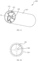
- FIG. 1A is a perspective view of a flow equalizing device 100 according to one embodiment of the present application
- FIG. 1B is a cross-sectional view of the flow equalizing device 100 shown in FIG. 1A
- the flow equalizing device 100 includes a pipeline 110, four blades 101, and a shaft rod 140.
- the pipeline 110 is cylindrical and has an inner wall 112.
- the pipeline 110 further comprises an inlet and an outlet at two ends, and has a central axis X.
- the shaft rod 140 is generally cylindrical, is formed by extending along the central axis X, and is coaxially arranged with the central axis X.
- the four blades 101 are connected to the shaft rod 140 and the pipeline 110.
- FIG. 2A is a perspective view of the flow equalizing device 100 shown in FIG. 1A
- FIG. 2B is a front view of the flow equalizing device 100 shown in FIG. 1A , in which the pipeline 110 is not shown, so as to illustrate the specific structure of the four blades 101 and the shaft rod 140.
- the four blades 101 are arranged around the central axis X in a helical pattern, so that the fluid in the pipeline 110 can be divided into four streams flowing in a spiral direction across the cross-section (i.e., the section in the radial direction) of the pipeline 110.
- the four blades 101 are identical in structure and are evenly arranged in the circumferential direction of the pipeline 110.
- each blade 101 is connected to (i.e., in contact with) the inner wall 112 of the pipeline 110, and the other side of each blade 101 is connected to (i.e., in contact with) the shaft rod 140, thereby forming four sector-shaped chambers inside the pipeline 110.
- Each blade 101 extends from one end of the shaft rod 140 to wind around the central axis X and rotates along the central axis X for a certain distance.
- the blade 101 completes one turn.
- point A on the blade 101 reaches point B after rotating 360° and point C after rotating an additional 180°.
- the blades 101 in the flow equalizing device shown in FIGS. 1A-2B complete one and a half turns (i.e., 1.5 turns).
- the blades 101 have a rotation angle ⁇ . More specifically, the rotation angle ⁇ is the acute angle formed by the tangent on the blade 101 at any point on the edge of the blade 101 and the cross-section of the pipeline 110.
- the blades 101 When each of the blades 101 has a rotation angle ⁇ that satisfies 25° ⁇ ⁇ ⁇ 75°, the blades 101 not only can divide the fluid in the pipeline 110 into four streams across the cross-section of the pipeline 110, but also can impart a good rotational velocity to the fluid, causing the liquid to stay close to the inner wall 112 of the pipeline 110 during the flow of the fluid.
- the blade 101 is provided with circular holes 130.
- the circular holes 130 are arranged to penetrate the blade 101, such that two adjacent streams of the fluid are in communication through the circular holes 130.
- Several circular holes 130 are evenly distributed circumferentially around the central axis X along the pipeline 110.
- the center of each of the circular holes 130 is at the same distance from the central axis X, and the circumferential spacing between the several circular holes 130 is uniform.
- the shortest distance D from the circular holes 130 to the central axis X satisfies: D/R > 1/2, where R is the radius of the inner wall 112 of the pipeline 110.
- the sum S of the areas of the circular holes 130 on a single blade 101 on the surface of the unit number of turns satisfies: 1/10 ⁇ S/A ⁇ 1/4, where A represents the cross-sectional area of the pipeline 110.
- the distance K from the ends of the four blades 101 to the outlet of the pipeline 110 satisfies: 0.5R ⁇ K ⁇ 3R (as shown in FIG. 6B ).
- FIG. 3 is an expanded view of a blade 101 of the flow equalizing device 100 shown in FIG. 1A , where the length L of the blade is the length of one full turn of the blade 101.
- the blade 101 in FIG. 3 is the blade 101 in FIG. 1A that is straightened, so that the inner edge of the blade 101 is parallel to the central axis X.
- a metal material can be shaped into the structure shown in FIG. 3 , then the blade 101 is bent, and the blade 101 is connected to the shaft rod 140 and the pipeline 110.
- the centers of the circular holes 130 are arranged to be parallel to the central axis X, with a certain spacing between adjacent two circular holes 130.
- the distance D from the inner edge of the circular holes 130 to the central axis X satisfies: D/R > 1/2.
- the area of each circular hole 130 is M.
- S1 i ⁇ M.
- the area sum S S1 satisfies 1 / 10 ⁇ i ⁇ M A ⁇ 1 / 4 .
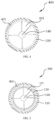
- FIG. 4 is a cross-sectional view of a flow equalizing device 400 according to another embodiment of the present application.
- the flow equalizing device 400 shown in FIG. 4 is substantially the same as the flow equalizing device 100 shown in FIGS. 1A-2B , and the same portions will not be repeated.
- the flow equalizing device 400 shown in FIG. 4 is different from the flow equalizing device 100 shown in FIGS. 1A-2B in that in the flow equalizing device 100, the outer edges of the four blades 101 are in contact and connected with the inner wall 112 of the pipeline 110, thereby forming four independent chambers. These four independent chambers are in communication through several circular holes 130.
- the four blades 101 do not have circular holes 130 thereon, and there is a gap 401 between the outer edges of the four blades 101 and the inner wall 112 of the pipeline 110.
- the four blades 101 can generally divide the interior of the pipeline 110 into four chambers. These four chambers can be in communication through the gap 401.
- the unit area sum S2 of the gap 401 equals the annular cross-sectional area.
- FIG. 5 is a cross-sectional view of a flow equalizing device 500 according to yet another embodiment of the present application.
- the flow equalizing device 500 shown in FIG. 5 is substantially the same as the flow equalizing device 100 shown in FIGS. 1A-2B , and the same portions will not be repeated.
- the flow equalizing device 500 shown in FIG. 5 is different from the flow equalizing device 100 shown in FIGS. 1A-2B in that in the flow equalizing device 100, the outer edges of the four blades 101 are in contact and connected with the inner wall 112 of the pipeline 110, thereby forming four independent chambers. These four independent chambers are in communication through several circular holes 130.
- the flow equalizing device 500 there is a gap 401 between the outer edges of the four blades 101 and the inner wall 112 of the pipeline 110.
- the four blades 101 can generally divide the interior of the pipeline 110 into four chambers. These four chambers can be in communication through the gap 401 and several circular holes 130.
- shaft rod 140 is shown in the present application, the shaft rod 140 may not be provided in other examples, and at least two blades may be fixed and connected by other means.
- the present application provides a flow equalizing device, where there is a space between the blades and the inner wall of the pipeline and/or through holes are provided on the blades, thereby forming a gap on the cross section of the pipeline, such that the at least two streams of fluid can circulate through the gap.
- the flow equalizing device of the present application has a simple structure and can achieve a uniform fluid flow in the circumferential direction. Specifically, in the flow equalizing device, at least two blades are helically arranged to substantially divide the interior of the pipeline 110 into at least two independent chambers. Before a fluid comprising a liquid and a gas enters the flow equalizing device, the diverting of the liquid and the gas is not regular. Once the fluid enters the flow equalizing device, it flows in a generally helical pattern. Since the density of the liquid is higher than the density of the gas, the liquid is positioned close to the inner wall of the pipe, while the gas is positioned close to the central axis X.
- the liquid When the liquid is unevenly distributed in the circumferential direction, it can flow between the chambers through the through holes or space (i.e., gaps), thereby leading to an annular diverting in the circumferential direction and thus achieving an effect of an even diverting of the liquid in the circumferential direction.
- the gas since the liquid is distributed in an annular shape in the circumferential direction, the gas can also be concentrated near the central axis X and distributed evenly in the circumferential direction.
- the flow equalizing device of the present application can also reduce the pressure drop of the fluid while equalizing the flow.
- a diverting device can mix a gas and a liquid thoroughly and then divide the flow.
- the diverting device in the prior art may lead to energy loss in the fluid, resulting in a great pressure drop.
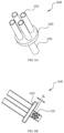
- FIG. 6A is a perspective view of a diverting device 600 according to the present application
- FIG. 6B is an axial cross-sectional view of the diverting device shown in FIG. 6A
- the diverting device 600 comprises a flow equalizing device, four diverting pipes 601, and a diverter 602.
- the flow equalizing device may be any of the flow equalizing devices within the scope of protection of the present application.
- the diverter 602 is generally disc-shaped with a certain thickness and can form a diverter chamber 610.
- An inlet and four outlets are provided on two sides of the diverter 602, respectively, and are in communication with the diverter chamber 610.
- the inlet of the diverter 602 is connected to the outlet of the flow equalizing device (i.e., the outlet of the pipeline 110), and the four outlets of the diverter 602 are connected to the inlets of the four diverting pipes 601, respectively, so that the fluid entering the flow equalizing device through its inlet (i.e., the inlet of the pipeline 110) can flow into the diverter 602.
- the fluid then flows radially within the diverter 602 and enters the four diverting pipes 601. Since the flow equalizing device of the present application can achieve a uniform distribution of liquid and gas in the circumferential direction, when the fluid flows into the diverter 602, the quantities of the liquid and the gas can be evenly distributed among the four diverting pipes 601.
- the diverting device 600 when the diverting device 600 is placed upstream of at least two heat exchangers, it not only can distribute the liquid and the gas evenly to each heat exchanger, so that all heat exchangers achieve uniform heat exchange, but also can reduce the liquid pressure drop before entering the heat exchangers.
- FIG. 7A is a simulation diagram of the flow rate of the fluid at an outlet of the pipeline of a diverting device with no gap.
- FIG. 7B is a simulation diagram of the flow rate of a fluid at an outlet of the pipeline of a diverting device of the present application.
- the blades are connected to the shaft rod and the inner wall of the pipeline with no gap provided.
- the diverting device shown in FIG. 7A the blades are connected to the shaft rod and the inner wall of the pipeline with no gap provided.
- the blades are connected to the shaft rod and the inner wall of the pipeline with gap provided. More specifically, through holes are provided on the blades thereof.
- FIGS. 7A and 7B the fluid distribution in FIG. 7A is uneven. Although four fluid streams can be substantially formed under the guidance of the helical blades, substantially still four streams remain at the outlet of the pipeline, leading to poor fluid diverting. While in FIG. 7B , the fluid forms substantially four streams under the guidance of the helical blades, but due to the presence of gaps, the fluid can be evenly distributed circumferentially at the outlet of the pipeline.
Landscapes
- Engineering & Computer Science (AREA)
- General Engineering & Computer Science (AREA)
- Mechanical Engineering (AREA)
- Physics & Mathematics (AREA)
- Fluid Mechanics (AREA)
- Thermal Sciences (AREA)
- Pipe Accessories (AREA)
Abstract
Description
- The present application relates to the field of flow equalizing devices, and in particular to a diverting device comprising a flow equalizing device.
- In the prior art, a fluid in a pipeline includes a liquid and a gas. Due to the differences in the density and velocity between the liquid flow and the gas flow, their distributions within the pipeline are also different, thereby leading to an uneven circumferential diverting of the liquid and the gas within the pipeline when the fluid exits the pipeline.
- Illustrative embodiments of the present application can solve at least some of the above problems.
- According to a first aspect of the present application, the present application provides a flow equalizing device, which comprises a pipeline and at least two blades. The pipeline is cylindrical and has a central axis. The at least two blades are arranged in the pipeline, and the at least two blades are arranged along a helical line around the central axis, such that a fluid in the pipeline can be divided into at least two streams of fluid to flow in a helical direction on the cross section of the pipeline. The at least two blades are spaced apart from an inner wall of the pipeline and/or the at least two blades are provided with through holes, thereby forming a gap on the cross section of the pipeline, such that the at least two streams of fluid can circulate through the gap.
- According to the flow equalizing device of the first aspect mentioned above, the radius of the inner wall of the pipeline is R, and the cross-sectional area of the pipeline is A. On any cross-section, the sum S of the unit areas of the gaps satisfies: 1/10 ≤ S/A ≤ 1/4; and the shortest distance D between the gaps and the central axis satisfies: D/R > 1/2.
- According to the flow equalizing device of the first aspect mentioned above, the edges of the at least two blades are in contact with the inner wall of the pipeline.
- According to the flow equalizing device of the first aspect mentioned above, the sum S of the unit areas of the gaps is the sum of the areas of the through holes on the at least two blades on the surface of the unit number of turns of the blades.
- According to the flow equalizing device of the first aspect mentioned above, the through holes are several circular holes and are evenly distributed circumferentially around the central axis along the pipeline.
- According to the flow equalizing device of the first aspect mentioned above, each of the at least two blades has a rotation angle φ that satisfies: 25° ≤ φ ≤ 75°, where the rotation angle φ is the acute angle formed by the tangent at any point on the edges of the at least two blades and the cross-section of the pipeline.
- According to the flow equalizing device of the first aspect mentioned above, the number of turns of rotation n of each of the at least two blades satisfies: 0.25 ≤ n ≤ 3.
- According to the flow equalizing device of the first aspect mentioned above, the distance K from the ends of the at least two blades to the outlet of the pipeline satisfies: 0.5R ≤ K ≤ 3R.
- According to the flow equalizing device of the first aspect mentioned above, the flow equalizing device further includes a shaft rod, which is formed by extending along the central axis, and the at least two blades are connected to the shaft rod.
- According to a second aspect of the present application, the present application provides a diverting device, which includes the above-mentioned flow equalizing device, at least two diverting pipes, and a diverter. The inlet of the diverter is connected to the outlet of the pipeline, and the at least two outlets of the diverter are correspondingly connected to the inlets of the at least two diverting pipes.
- The flow equalizing device of the present application can enable the fluid to have an equalized flow in the circumferential direction.
- The features and advantages of the present application can be better understood by reading the following detailed description with reference to the accompanying drawings. Throughout the drawings, the same reference numerals indicate the same components, where:
-
FIG. 1A is a perspective view of a flow equalizing device according to one embodiment of the present application; -
FIG. 1B is a cross-sectional view of the flow equalizing device shown inFIG. 1A ; -
FIG. 2A is a perspective view of the flow equalizing device shown inFIG. 1A , wherein no pipeline is illustrated; -
FIG. 2B is a front view of the flow equalizing device shown inFIG. 1A , wherein no pipeline is illustrated; -
FIG. 3 is an expanded view of a blade of the flow equalizing device shown inFIG. 1A ; -
FIG. 4 is a cross-sectional view of a flow equalizing device according to another embodiment of the present application; -
FIG. 5 is a cross-sectional view of a flow equalizing device according to yet another embodiment of the present application; -
FIG. 6A is a perspective view of a diverting device according to the present application; -
FIG. 6B is an axial cross-sectional view of the diverting device shown inFIG. 6A ; -
FIG. 7A is a simulation diagram of the flow rate of the fluid at an outlet of the pipeline of a diverting device with no gap; -
FIG. 7B is a simulation diagram of the flow rate of a fluid at an outlet of the pipeline of a diverting device of the present application. - Various specific embodiments of the present invention will be described below with reference to the accompanying drawings, which form part of this specification. It should be understood that although directional terms, such as "front," "rear," "top," "bottom," "left," "right," and the like, are used in the present invention to describe the direction or orientation of various example structural parts and components of the present invention, these terms are used herein solely for the purpose of description and determined based on the example orientations shown in the drawings. Since the disclosed embodiments of the present invention can be arranged in different directions, these directional terms are used for explanatory purposes only and should not be construed as limiting. In the following drawings, the same reference numbers are used to denote the same parts.
-
FIG. 1A is a perspective view of aflow equalizing device 100 according to one embodiment of the present application, andFIG. 1B is a cross-sectional view of theflow equalizing device 100 shown inFIG. 1A . As shown inFIGS. 1A-1B , theflow equalizing device 100 includes apipeline 110, fourblades 101, and ashaft rod 140. Thepipeline 110 is cylindrical and has aninner wall 112. Thepipeline 110 further comprises an inlet and an outlet at two ends, and has a central axis X. Theshaft rod 140 is generally cylindrical, is formed by extending along the central axis X, and is coaxially arranged with the central axis X. The fourblades 101 are connected to theshaft rod 140 and thepipeline 110. -
FIG. 2A is a perspective view of theflow equalizing device 100 shown inFIG. 1A , andFIG. 2B is a front view of theflow equalizing device 100 shown inFIG. 1A , in which thepipeline 110 is not shown, so as to illustrate the specific structure of the fourblades 101 and theshaft rod 140. As shown inFIGS. 2A-2B , the fourblades 101 are arranged around the central axis X in a helical pattern, so that the fluid in thepipeline 110 can be divided into four streams flowing in a spiral direction across the cross-section (i.e., the section in the radial direction) of thepipeline 110. Specifically, the fourblades 101 are identical in structure and are evenly arranged in the circumferential direction of thepipeline 110. One side of eachblade 101 is connected to (i.e., in contact with) theinner wall 112 of thepipeline 110, and the other side of eachblade 101 is connected to (i.e., in contact with) theshaft rod 140, thereby forming four sector-shaped chambers inside thepipeline 110. Eachblade 101 extends from one end of theshaft rod 140 to wind around the central axis X and rotates along the central axis X for a certain distance. When any point on the outer edge of a blade 101 (i.e., the side close to the pipeline 110) rotates 360°, theblade 101 completes one turn. As shown inFIG. 2A , point A on theblade 101 reaches point B after rotating 360° and point C after rotating an additional 180°. Thus, theblades 101 in the flow equalizing device shown inFIGS. 1A-2B complete one and a half turns (i.e., 1.5 turns). - In addition, the
blades 101 have a rotation angle φ. More specifically, the rotation angle φ is the acute angle formed by the tangent on theblade 101 at any point on the edge of theblade 101 and the cross-section of thepipeline 110. When each of theblades 101 has a rotation angle φ that satisfies 25° ≤ φ ≤ 75°, theblades 101 not only can divide the fluid in thepipeline 110 into four streams across the cross-section of thepipeline 110, but also can impart a good rotational velocity to the fluid, causing the liquid to stay close to theinner wall 112 of thepipeline 110 during the flow of the fluid. - Furthermore, the
blade 101 is provided withcircular holes 130. Thecircular holes 130 are arranged to penetrate theblade 101, such that two adjacent streams of the fluid are in communication through thecircular holes 130. Severalcircular holes 130 are evenly distributed circumferentially around the central axis X along thepipeline 110. In other words, the center of each of thecircular holes 130 is at the same distance from the central axis X, and the circumferential spacing between the severalcircular holes 130 is uniform. The shortest distance D from thecircular holes 130 to the central axis X satisfies: D/R > 1/2, where R is the radius of theinner wall 112 of thepipeline 110. In addition, the sum S of the areas of thecircular holes 130 on asingle blade 101 on the surface of the unit number of turns satisfies: 1/10 ≤ S/A ≤ 1/4, where A represents the cross-sectional area of thepipeline 110. - Furthermore, the distance K from the ends of the four
blades 101 to the outlet of thepipeline 110 satisfies: 0.5R ≤ K ≤ 3R (as shown inFIG. 6B ). -
FIG. 3 is an expanded view of ablade 101 of theflow equalizing device 100 shown inFIG. 1A , where the length L of the blade is the length of one full turn of theblade 101. Theblade 101 inFIG. 3 is theblade 101 inFIG. 1A that is straightened, so that the inner edge of theblade 101 is parallel to the central axis X. In actual manufacturing, as an example, a metal material can be shaped into the structure shown inFIG. 3 , then theblade 101 is bent, and theblade 101 is connected to theshaft rod 140 and thepipeline 110. - As shown in
FIG. 3 , the centers of thecircular holes 130 are arranged to be parallel to the central axis X, with a certain spacing between adjacent twocircular holes 130. The distance D from the inner edge of thecircular holes 130 to the central axis X satisfies: D/R > 1/2. The area of eachcircular hole 130 is M. There are icircular holes 130 per unit number of turns. Thus, for a single blade, the sum of the areas of thecircular holes 130 per unit number of turns is S1 = i × M. The area sum S=S1 satisfies
-
FIG. 4 is a cross-sectional view of aflow equalizing device 400 according to another embodiment of the present application. Theflow equalizing device 400 shown inFIG. 4 is substantially the same as theflow equalizing device 100 shown inFIGS. 1A-2B , and the same portions will not be repeated. Theflow equalizing device 400 shown inFIG. 4 is different from theflow equalizing device 100 shown inFIGS. 1A-2B in that in theflow equalizing device 100, the outer edges of the fourblades 101 are in contact and connected with theinner wall 112 of thepipeline 110, thereby forming four independent chambers. These four independent chambers are in communication through severalcircular holes 130. However, in theflow equalizing device 400, the fourblades 101 do not havecircular holes 130 thereon, and there is agap 401 between the outer edges of the fourblades 101 and theinner wall 112 of thepipeline 110. The fourblades 101 can generally divide the interior of thepipeline 110 into four chambers. These four chambers can be in communication through thegap 401. The unit area sum S2 of thegap 401 equals the annular cross-sectional area. The area sum is S=S2, and it satisfies: 1/10 ≤ S/A ≤ 1/4. -
FIG. 5 is a cross-sectional view of aflow equalizing device 500 according to yet another embodiment of the present application. Theflow equalizing device 500 shown inFIG. 5 is substantially the same as theflow equalizing device 100 shown inFIGS. 1A-2B , and the same portions will not be repeated. Theflow equalizing device 500 shown inFIG. 5 is different from theflow equalizing device 100 shown inFIGS. 1A-2B in that in theflow equalizing device 100, the outer edges of the fourblades 101 are in contact and connected with theinner wall 112 of thepipeline 110, thereby forming four independent chambers. These four independent chambers are in communication through severalcircular holes 130. However, in theflow equalizing device 500, there is agap 401 between the outer edges of the fourblades 101 and theinner wall 112 of thepipeline 110. The fourblades 101 can generally divide the interior of thepipeline 110 into four chambers. These four chambers can be in communication through thegap 401 and severalcircular holes 130. The unit area sum of thegap 401 and the circular holes 130 S=S1 + S2 = i × M + S2, and it satisfies: 1/10 ≤ S/A ≤ 1/4. - A person skilled in the art can understand that, although
circular holes 130 are illustrated in the present application, any shape of through holes falls within the scope of protection of the present application. - A person skilled in the art can understand that, although the present application illustrates that the center of each
circular hole 130 is at the same distance from the central axis X, the arrangement where thecircular holes 130 are radially arranged in at least one row also falls within the scope of protection of the present application. - A person skilled in the art can understand that, although several
circular holes 130 shown in the present application are evenly distributed around the central axis X along the circumferential direction of thepipeline 110, other arrangements of any shape are also within the scope of protection of the present application. - A person skilled in the art can understand that the blades in the present application are described as having an outer contour (i.e., outer edge) that is circular in the sectional view. Therefore, even in some examples where the through holes are located at the edges of the blades, they still fall within the scope of the "through holes" described in the present application.
- A person skilled in the art can understand that, although four
blades 101 are shown in the present application, at least twoblades 101 are within the scope of protection of the present application. - A person skilled in the art can understand that, although the
shaft rod 140 is shown in the present application, theshaft rod 140 may not be provided in other examples, and at least two blades may be fixed and connected by other means. - A person skilled in the art can understand that, although the number of rotations n is shown as 1.5 in the present application, the number of rotations n can satisfy: 0.25 ≤ n ≤ 3 in other examples.
- Thus, the present application provides a flow equalizing device, where there is a space between the blades and the inner wall of the pipeline and/or through holes are provided on the blades, thereby forming a gap on the cross section of the pipeline, such that the at least two streams of fluid can circulate through the gap.
- The flow equalizing device of the present application has a simple structure and can achieve a uniform fluid flow in the circumferential direction. Specifically, in the flow equalizing device, at least two blades are helically arranged to substantially divide the interior of the
pipeline 110 into at least two independent chambers. Before a fluid comprising a liquid and a gas enters the flow equalizing device, the diverting of the liquid and the gas is not regular. Once the fluid enters the flow equalizing device, it flows in a generally helical pattern. Since the density of the liquid is higher than the density of the gas, the liquid is positioned close to the inner wall of the pipe, while the gas is positioned close to the central axis X. When the liquid is unevenly distributed in the circumferential direction, it can flow between the chambers through the through holes or space (i.e., gaps), thereby leading to an annular diverting in the circumferential direction and thus achieving an effect of an even diverting of the liquid in the circumferential direction. In addition, since the liquid is distributed in an annular shape in the circumferential direction, the gas can also be concentrated near the central axis X and distributed evenly in the circumferential direction. Moreover, the flow equalizing device of the present application can also reduce the pressure drop of the fluid while equalizing the flow. Specifically, in the prior art, a diverting device can mix a gas and a liquid thoroughly and then divide the flow. However, compared with the flow equalizing device of the present application, the diverting device in the prior art may lead to energy loss in the fluid, resulting in a great pressure drop. -
FIG. 6A is a perspective view of a divertingdevice 600 according to the present application, andFIG. 6B is an axial cross-sectional view of the diverting device shown inFIG. 6A . As shown inFIGS. 6A-6B , the divertingdevice 600 comprises a flow equalizing device, four divertingpipes 601, and adiverter 602. The flow equalizing device may be any of the flow equalizing devices within the scope of protection of the present application. Thediverter 602 is generally disc-shaped with a certain thickness and can form adiverter chamber 610. An inlet and four outlets are provided on two sides of thediverter 602, respectively, and are in communication with thediverter chamber 610. The inlet of thediverter 602 is connected to the outlet of the flow equalizing device (i.e., the outlet of the pipeline 110), and the four outlets of thediverter 602 are connected to the inlets of the four divertingpipes 601, respectively, so that the fluid entering the flow equalizing device through its inlet (i.e., the inlet of the pipeline 110) can flow into thediverter 602. The fluid then flows radially within thediverter 602 and enters the four divertingpipes 601. Since the flow equalizing device of the present application can achieve a uniform distribution of liquid and gas in the circumferential direction, when the fluid flows into thediverter 602, the quantities of the liquid and the gas can be evenly distributed among the four divertingpipes 601. - As one application, when the diverting
device 600 is placed upstream of at least two heat exchangers, it not only can distribute the liquid and the gas evenly to each heat exchanger, so that all heat exchangers achieve uniform heat exchange, but also can reduce the liquid pressure drop before entering the heat exchangers. - A person skilled in the art can understand that, although the
diverter 602 is depicted as generally disc-shaped in the present application, any shape (e.g., conical) of the diverter falls within the scope of protection of the present application, as long as the diverter includes one inlet and at least two outlets.FIG. 7A is a simulation diagram of the flow rate of the fluid at an outlet of the pipeline of a diverting device with no gap.FIG. 7B is a simulation diagram of the flow rate of a fluid at an outlet of the pipeline of a diverting device of the present application. In the diverting device shown inFIG. 7A , the blades are connected to the shaft rod and the inner wall of the pipeline with no gap provided. In the diverting device shown inFIG. 7B , the blades are connected to the shaft rod and the inner wall of the pipeline with gap provided. More specifically, through holes are provided on the blades thereof. As can be seen fromFIGS. 7A and 7B , the fluid distribution inFIG. 7A is uneven. Although four fluid streams can be substantially formed under the guidance of the helical blades, substantially still four streams remain at the outlet of the pipeline, leading to poor fluid diverting. While inFIG. 7B , the fluid forms substantially four streams under the guidance of the helical blades, but due to the presence of gaps, the fluid can be evenly distributed circumferentially at the outlet of the pipeline. - While the present disclosure has been described in conjunction with the examples of the embodiments mentioned above, various alternatives, modifications, variations, improvements, and/or equivalent solutions, whether known or foreseeable in the near future, may be readily apparent to those skilled in the art. Furthermore, the technical effects and/or technical problems described in this specification are exemplary and not limiting; therefore, the disclosure in this specification may be applied to other technical problems and achieve other technical effects and/or may solve other technical problems. Therefore, the examples of the embodiments of the present disclosure described above are intended to be illustrative and not restrictive. Various changes can be made without departing from the spirit or scope of the present invention. Therefore, the present disclosure is intended to cover all known or previously developed alternatives, modifications, variations, improvements, and/or equivalent solutions.
Claims (10)
- A flow equalizing device,characterized in thatthe flow equalizing device comprises:- a pipeline (110), wherein the pipeline (110) is cylindrical and has a central axis; and- at least two blades (101), wherein the at least two blades (101) are arranged in the pipeline (110), and the at least two blades (101) are arranged along a helical line around the central axis, such that a fluid in the pipeline (110) can be divided into at least two streams of fluid to flow in a helical direction on the cross section of the pipeline (110);wherein there is a space (401) between the at least two blades (101) and an inner wall (112) of the pipeline (110) and/or the at least two blades (101) are provided with through holes, thereby forming a gap on the cross section of the pipeline (110), such that the at least two streams of fluid can circulate through the gap.
- The flow equalizing device according to claim 1, characterized in that- the radius of the inner wall (112) of the pipeline (110) is R, and the cross-sectional area of the pipeline (110) is A;- on any cross-section, the sum S of the unit areas of the gaps satisfies:
 - the shortest distance D between the gaps and the central axis satisfies:
- The flow equalizing device according to claim 2,
characterized in that
the edges of the at least two blades (101) are in contact with the inner wall (112) of the pipeline (110). - The flow equalizing device according to claim 3,
characterized in that
the sum S of the unit areas of the gaps is the sum of the areas of the through holes on the at least two blades (101) on the surface of the unit number of turns of the blades (101). - The flow equalizing device according to claim 4,
characterized in that
the through holes are several circular holes and are evenly distributed circumferentially around the central axis along the pipeline (110). - The flow equalizing device according to claim 1,
characterized in thateach of the at least two blades (101) has a rotation angle φ that satisfies: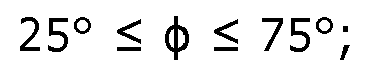 where the rotation angle φ is the acute angle formed by the tangent on the blades (101) at any point on the edges of the at least two blades (101) and the cross-section of the pipeline (110).
 - The flow equalizing device according to claim 1,
characterized in that
the number of turns of rotation n of each of the at least two blades (101) satisfies: 0.25 ≤ n ≤ 3. - The flow equalizing device according to claim 1,
characterized in that
the distance K from the ends of the at least two blades (101) to the outlet of the pipeline (110) satisfies: 0.5R ≤ K ≤ 3R. - The flow equalizing device according to claim 1,
characterized in that
the flow equalizing device further comprises:- a shaft rod (140), the shaft rod (140) being formed by extending along the central axis, and the at least two blades (101) being connected to the shaft rod (140). - A diverting device,
characterized in that
the diverting device comprises:- the flow equalizing device according to any one of claims 1-9;- at least two diverting pipes (601), and- a diverter (602), wherein the inlet of the diverter (602) is connected to the outlet of the pipeline (110), and the at least two outlets of the diverter (602) are correspondingly connected to the inlets of the at least two diverting pipes (601).
Applications Claiming Priority (2)
| Application Number | Priority Date | Filing Date | Title |
|---|---|---|---|
| CN202210097330.1A CN114542555B (en) | 2022-01-27 | 2022-01-27 | Current balancing and current splitting devices |
| PCT/CN2022/142273 WO2023142836A1 (en) | 2022-01-27 | 2022-12-27 | Flow equalizing device and diverting device |
Publications (2)
| Publication Number | Publication Date |
|---|---|
| EP4477894A1 true EP4477894A1 (en) | 2024-12-18 |
| EP4477894A4 EP4477894A4 (en) | 2026-04-08 |
Family
ID=81673477
Family Applications (1)
| Application Number | Title | Priority Date | Filing Date |
|---|---|---|---|
| EP22923622.9A Pending EP4477894A4 (en) | 2022-01-27 | 2022-12-27 | FLOW EQUALIZING DEVICE AND DISPATCH DEVICE |
Country Status (4)
| Country | Link |
|---|---|
| US (1) | US20260002555A1 (en) |
| EP (1) | EP4477894A4 (en) |
| CN (1) | CN114542555B (en) |
| WO (1) | WO2023142836A1 (en) |
Families Citing this family (3)
| Publication number | Priority date | Publication date | Assignee | Title |
|---|---|---|---|---|
| US11719471B2 (en) | 2021-09-29 | 2023-08-08 | Johnson Controls Tyco IP Holdings LLP | Energy efficient heat pump with heat exchanger counterflow arrangement |
| CN114542555B (en) * | 2022-01-27 | 2024-07-12 | 约克广州空调冷冻设备有限公司 | Current balancing and current splitting devices |
| US20250334358A1 (en) * | 2024-04-29 | 2025-10-30 | Pratt & Whitney Canada Corp. | Heat exchanger having a mixing chamber with fins |
Family Cites Families (26)
| Publication number | Priority date | Publication date | Assignee | Title |
|---|---|---|---|---|
| DE10163812A1 (en) * | 2001-12-22 | 2003-07-03 | Mann & Hummel Filter | Device for sound absorption in a pipe duct |
| KR200302161Y1 (en) * | 2002-10-10 | 2003-01-30 | 윤정희 | A decompression coupling stainless pipe |
| FR2860854B1 (en) * | 2003-10-10 | 2008-09-05 | Manuli Auto France | ACOUSTIC PERTURBATION ATTENUATING DEVICE AND CONDITIONING CIRCUIT INCLUDING SUCH A DEVICE |
| JP2011092838A (en) * | 2009-10-28 | 2011-05-12 | Osaka Gas Co Ltd | Apparatus for mixing fluids, and denitrifying apparatus |
| CN202893218U (en) * | 2012-11-23 | 2013-04-24 | 重庆大学 | Low water loss pipeline mixer |
| CN103016469A (en) * | 2012-12-20 | 2013-04-03 | 西安交通大学 | Vortex device and application of vortex device in transportation of high water content crude oil |
| CN103736410B (en) * | 2013-12-16 | 2015-05-13 | 北京化工大学 | Blade-carrying perforate spheroidicity dynamic mixer used for pipeline |
| CN104154685A (en) * | 2014-08-28 | 2014-11-19 | 珠海格力电器股份有限公司 | Flow equalizing device and air conditioner with same |
| CN204186696U (en) * | 2014-09-19 | 2015-03-04 | 重庆市鸿嘉洪节能科技有限公司 | Spiral vortex accelerates pipeline |
| US10086333B2 (en) * | 2015-02-24 | 2018-10-02 | Tenneco Automotive Operating Company Inc. | Dual auger mixing system |
| KR101647100B1 (en) * | 2015-03-10 | 2016-08-09 | 주식회사 포스코건설 | Screw vane for swirl reduction |
| CN104776654B (en) * | 2015-03-26 | 2018-04-13 | 珠海格力电器股份有限公司 | Shunt, heat exchanger and air conditioner |
| ITUB20155897A1 (en) * | 2015-11-25 | 2017-05-25 | T&P S P A | DEVICE FOR MEASURING AND VOLUMETRIC CONTROL OF A FLUID |
| CN106090520B (en) * | 2016-08-05 | 2019-07-19 | 中国船舶重工集团公司第七一九研究所 | A kind of even flow field device designed using big and small blade |
| CN206724528U (en) * | 2017-04-12 | 2017-12-08 | 广东美的暖通设备有限公司 | The current equalizing structure and distributor of the distributor of refrigerating plant |
| CN107906086A (en) * | 2017-10-17 | 2018-04-13 | 常州大学 | A kind of sleeve type spiral flow generating apparatus |
| CN207813704U (en) * | 2018-01-26 | 2018-09-04 | 杭州银轮科技有限公司 | A kind of static mixer for diesel engine vent gas post-processing |
| CN108591195A (en) * | 2018-06-06 | 2018-09-28 | 中国船舶重工集团公司第七〇九研究所 | A kind of pipeline even flow field device of self-regulation flow distortion |
| CN209131738U (en) * | 2018-12-25 | 2019-07-19 | 重庆耐德工业股份有限公司 | A kind of flowmeter |
| CN110671565B (en) * | 2019-09-06 | 2022-01-21 | 北京建筑大学 | A shunt structure for fluid is from reposition of redundant personnel |
| CN111140721B (en) * | 2020-01-17 | 2021-01-01 | 浙江大学 | Spiral noise reduction device and method thereof |
| CN111359466B (en) * | 2020-03-17 | 2021-10-15 | 华东理工大学 | Device and method for enhancing two-phase mixed mass transfer |
| CN111577655B (en) * | 2020-04-14 | 2021-11-05 | 约克广州空调冷冻设备有限公司 | Blade and axial flow impeller using the same |
| CN111569687B (en) * | 2020-04-23 | 2023-04-18 | 上海灿越化工科技有限公司 | Unpowered spiral-flow type mixing device and mixing method thereof |
| CN111692451A (en) * | 2020-05-07 | 2020-09-22 | 温州乾含节能科技有限公司 | Flow equalizing device used in pipeline |
| CN114542555B (en) * | 2022-01-27 | 2024-07-12 | 约克广州空调冷冻设备有限公司 | Current balancing and current splitting devices |
-
2022
- 2022-01-27 CN CN202210097330.1A patent/CN114542555B/en active Active
- 2022-12-27 US US18/833,359 patent/US20260002555A1/en active Pending
- 2022-12-27 EP EP22923622.9A patent/EP4477894A4/en active Pending
- 2022-12-27 WO PCT/CN2022/142273 patent/WO2023142836A1/en not_active Ceased
Also Published As
| Publication number | Publication date |
|---|---|
| CN114542555A (en) | 2022-05-27 |
| US20260002555A1 (en) | 2026-01-01 |
| EP4477894A4 (en) | 2026-04-08 |
| WO2023142836A1 (en) | 2023-08-03 |
| CN114542555B (en) | 2024-07-12 |
Similar Documents
| Publication | Publication Date | Title |
|---|---|---|
| US20260002555A1 (en) | Flow equalizing device and diverting device | |
| US4357991A (en) | Heat exchanger having improved tube layout | |
| US4062524A (en) | Apparatus for the static mixing of fluid streams | |
| TWI776162B (en) | Helically baffled heat exchanger and method of assembling a heat exchanger | |
| US20050077034A1 (en) | Static mixer-heat exchanger | |
| US3450199A (en) | Heat exchanger | |
| EP3394522B1 (en) | Fired heat exchanger | |
| US20180106561A1 (en) | Heat exchanger | |
| JPH05202912A (en) | Rectifier | |
| EP2977697A2 (en) | Heat exchanger and heat exchanging unit | |
| WO2018229756A1 (en) | Plate and shell heat exchanging system having a divided manifold tube | |
| JP4568973B2 (en) | Plate type heat exchanger | |
| CN112066606B (en) | Liquid separation structure and air conditioning with high liquid separation efficiency | |
| KR20220118997A (en) | heat exchanger | |
| EP0117820B1 (en) | Segmental baffle high performance shell and tube heat exchanger | |
| EP4367464B1 (en) | A shell-and-tube heat exchanger with helical baffles | |
| JPH1172104A (en) | Eddy current generator and method of manufacturing the same | |
| CN219415866U (en) | Heat exchange tube and heat exchanger | |
| CA1052765A (en) | Heat exchanger | |
| CN115950291B (en) | Heat exchange tube, heat exchanger and manufacturing method of heat exchange tube | |
| CN114963802B (en) | Curved baffle assembly for shell and tube heat exchanger and shell and tube heat exchanger | |
| US4397350A (en) | Flow guiding in tube bundle heat exchangers | |
| CN112539668A (en) | Heat exchanger and manufacturing method thereof | |
| CN111140721A (en) | Spiral noise reduction device and method thereof | |
| US3260306A (en) | Heat exchangers |
Legal Events
| Date | Code | Title | Description |
|---|---|---|---|
| STAA | Information on the status of an ep patent application or granted ep patent |
Free format text: STATUS: THE INTERNATIONAL PUBLICATION HAS BEEN MADE |
|
| PUAI | Public reference made under article 153(3) epc to a published international application that has entered the european phase |
Free format text: ORIGINAL CODE: 0009012 |
|
| STAA | Information on the status of an ep patent application or granted ep patent |
Free format text: STATUS: REQUEST FOR EXAMINATION WAS MADE |
|
| 17P | Request for examination filed |
Effective date: 20240827 |
|
| AK | Designated contracting states |
Kind code of ref document: A1 Designated state(s): AL AT BE BG CH CY CZ DE DK EE ES FI FR GB GR HR HU IE IS IT LI LT LU LV MC ME MK MT NL NO PL PT RO RS SE SI SK SM TR |
|
| DAV | Request for validation of the european patent (deleted) | ||
| DAX | Request for extension of the european patent (deleted) | ||
| REG | Reference to a national code |
Ref country code: DE Ref legal event code: R079 Free format text: PREVIOUS MAIN CLASS: F15D0001020000 Ipc: F15D0001000000 |
|
| A4 | Supplementary search report drawn up and despatched |
Effective date: 20260306 |
|
| RIC1 | Information provided on ipc code assigned before grant |
Ipc: F15D 1/00 20060101AFI20260302BHEP Ipc: F15D 1/02 20060101ALI20260302BHEP Ipc: F15D 1/04 20060101ALI20260302BHEP Ipc: F16L 55/027 20060101ALI20260302BHEP Ipc: F16L 41/03 20060101ALI20260302BHEP Ipc: B01F 25/4314 20220101ALI20260302BHEP Ipc: B01F 25/431 20220101ALI20260302BHEP Ipc: F28F 13/06 20060101ALI20260302BHEP Ipc: F28F 13/12 20060101ALI20260302BHEP |