EP4477869A1 - A method for manipulating a shape and/or a position of a wind turbine rotor blade shell member - Google Patents
A method for manipulating a shape and/or a position of a wind turbine rotor blade shell member Download PDFInfo
- Publication number
- EP4477869A1 EP4477869A1 EP23178616.1A EP23178616A EP4477869A1 EP 4477869 A1 EP4477869 A1 EP 4477869A1 EP 23178616 A EP23178616 A EP 23178616A EP 4477869 A1 EP4477869 A1 EP 4477869A1
- Authority
- EP
- European Patent Office
- Prior art keywords
- wind turbine
- turbine rotor
- rotor blade
- blade shell
- tensioning block
- Prior art date
- Legal status (The legal status is an assumption and is not a legal conclusion. Google has not performed a legal analysis and makes no representation as to the accuracy of the status listed.)
- Granted
Links
Images




Classifications
-
- F—MECHANICAL ENGINEERING; LIGHTING; HEATING; WEAPONS; BLASTING
- F03—MACHINES OR ENGINES FOR LIQUIDS; WIND, SPRING, OR WEIGHT MOTORS; PRODUCING MECHANICAL POWER OR A REACTIVE PROPULSIVE THRUST, NOT OTHERWISE PROVIDED FOR
- F03D—WIND MOTORS
- F03D80/00—Details, components or accessories not provided for in groups F03D1/00 - F03D17/00
- F03D80/50—Maintenance or repair
- F03D80/502—Maintenance or repair of rotors or blades
-
- F—MECHANICAL ENGINEERING; LIGHTING; HEATING; WEAPONS; BLASTING
- F03—MACHINES OR ENGINES FOR LIQUIDS; WIND, SPRING, OR WEIGHT MOTORS; PRODUCING MECHANICAL POWER OR A REACTIVE PROPULSIVE THRUST, NOT OTHERWISE PROVIDED FOR
- F03D—WIND MOTORS
- F03D1/00—Wind motors with rotation axis substantially parallel to the air flow entering the rotor
- F03D1/06—Rotors
- F03D1/065—Rotors characterised by their construction elements
- F03D1/0675—Rotors characterised by their construction elements of the blades
-
- F—MECHANICAL ENGINEERING; LIGHTING; HEATING; WEAPONS; BLASTING
- F03—MACHINES OR ENGINES FOR LIQUIDS; WIND, SPRING, OR WEIGHT MOTORS; PRODUCING MECHANICAL POWER OR A REACTIVE PROPULSIVE THRUST, NOT OTHERWISE PROVIDED FOR
- F03D—WIND MOTORS
- F03D1/00—Wind motors with rotation axis substantially parallel to the air flow entering the rotor
- F03D1/06—Rotors
- F03D1/065—Rotors characterised by their construction elements
- F03D1/0658—Arrangements for fixing wind-engaging parts to a hub
-
- F—MECHANICAL ENGINEERING; LIGHTING; HEATING; WEAPONS; BLASTING
- F03—MACHINES OR ENGINES FOR LIQUIDS; WIND, SPRING, OR WEIGHT MOTORS; PRODUCING MECHANICAL POWER OR A REACTIVE PROPULSIVE THRUST, NOT OTHERWISE PROVIDED FOR
- F03D—WIND MOTORS
- F03D1/00—Wind motors with rotation axis substantially parallel to the air flow entering the rotor
- F03D1/06—Rotors
- F03D1/065—Rotors characterised by their construction elements
- F03D1/0675—Rotors characterised by their construction elements of the blades
- F03D1/0677—Longitudinally segmented blades; Connectors therefor
-
- F—MECHANICAL ENGINEERING; LIGHTING; HEATING; WEAPONS; BLASTING
- F03—MACHINES OR ENGINES FOR LIQUIDS; WIND, SPRING, OR WEIGHT MOTORS; PRODUCING MECHANICAL POWER OR A REACTIVE PROPULSIVE THRUST, NOT OTHERWISE PROVIDED FOR
- F03D—WIND MOTORS
- F03D13/00—Assembly, mounting or commissioning of wind motors; Arrangements specially adapted for transporting wind motor components
- F03D13/40—Arrangements or methods specially adapted for transporting wind motor components
- F03D13/401—Arrangements or methods specially adapted for transporting wind motor components for transporting or storing blades
-
- Y—GENERAL TAGGING OF NEW TECHNOLOGICAL DEVELOPMENTS; GENERAL TAGGING OF CROSS-SECTIONAL TECHNOLOGIES SPANNING OVER SEVERAL SECTIONS OF THE IPC; TECHNICAL SUBJECTS COVERED BY FORMER USPC CROSS-REFERENCE ART COLLECTIONS [XRACs] AND DIGESTS
- Y02—TECHNOLOGIES OR APPLICATIONS FOR MITIGATION OR ADAPTATION AGAINST CLIMATE CHANGE
- Y02E—REDUCTION OF GREENHOUSE GAS [GHG] EMISSIONS, RELATED TO ENERGY GENERATION, TRANSMISSION OR DISTRIBUTION
- Y02E10/00—Energy generation through renewable energy sources
- Y02E10/70—Wind energy
- Y02E10/72—Wind turbines with rotation axis in wind direction
Definitions
- the invention relates to a method for manipulating a shape and/or a position of a first wind turbine rotor blade shell member.
- wind turbine rotor blades have continued to grow in size, making it more difficult to handle the wind turbine rotor blades and wind turbine rotor blade elements during production and transport. Whenever it becomes necessary to bring or maintain a wind turbine rotor blade shell member exactly in a desired position and/or shape, this may require applying substantial forces, which is difficult due to the complex shape of the wind turbine rotor blade shell members, and always includes a risk to damage the wind turbine rotor blade shell member's structure.
- the method is for manipulating a shape and/or a position of a first wind turbine rotor blade shell member, wherein the first wind turbine rotor blade shell member has a connection section and a first insert having a connection surface and being arranged in the connection section, the first insert being adapted to be screw-connected to another element of a wind turbine rotor, the method comprising the following steps:
- the wind turbine rotor may have a horizontal axis.
- the first wind turbine rotor blade shell member may be a wind turbine rotor blade half shell or another element of a wind turbine rotor blade comprising two or more parts connected with each other to form the entire rotor blade shell.
- the first wind turbine rotor blade shell member may also refer to a wind turbine rotor blade shell in its entirety, either when manufactured in one piece or when having been firmly assembled from two or more parts manufactured separately.
- the first wind turbine rotor blade shell member may extend over the entire length of the wind turbine rotor blade, from a root to a tip.
- first wind turbine rotor blade shell member may also be a longitudinal segment of a wind turbine rotor blade shell member or of an entire wind turbine rotor blade shell.
- connection section refers to a section of the first wind turbine rotor blade shell member adapted to be connected to another element of a wind turbine rotor.
- This other element may be, for example, a wind turbine rotor hub or an extender placed between a wind turbine rotor blade root and a wind turbine rotor hub.
- the other element may also be another element of a wind turbine rotor blade, in particular when the wind turbine rotor blade is assembled from two or more longitudinal segments.
- the connection section may be an end section of a first longitudinal segment of a rotor blade shell member facing another longitudinal segment of the same wind turbine rotor blade shell member. No matter to which other element of a wind turbine rotor the first wind turbine rotor blade shell member is to be connected to, the connection surface of the first insert, which is arranged in the connection section, will be facing the other element of the wind turbine rotor.
- the first insert has an inner thread into which the threaded bolt can be screwed into.
- the first insert may be a sleeve having a circular, circumferential outer surface.
- the first insert may also have another cross-sectional shape.
- the cross-sectional shape may vary or may be constant along a longitudinal direction of the first insert.
- the first insert may be rotationally symmetrical.
- the first insert may be made of a metal such as steel.
- a first tensioning block is provided and mounted to the first wind turbine rotor blade shell member.
- the first tensioning block need not to be block-shaped, in fact it may have any other shape as long as the same provides a contact surface suitable to be pressed against the connection surface of the first insert when the first tensioning block is mounted to the first wind turbine rotor blade shell member by means of the threaded bolt.
- the first tensioning block is mounted to the first wind turbine rotor blade shell member with a threaded bolt which is screwed into the first insert. The outer end or section of the threaded bolt not screwed into the first insert is connected to (or formed integrally with) the first tensioning block.
- the contact surface of the first tensioning block is pressed against the connection surface of the first insert with a pretensioning force.
- a pretensioning force is selected such that the interference fit is strong enough to transfer the lateral manipulating force applied to the first tensioning block.
- Applying a force to the first tensioning block in a lateral direction means in a direction at an angle with reference to a longitudinal axis of the first insert and/or its inner thread. The angle may be essentially a right angle, however, any manipulating forces deviating therefrom by 60° or less, in particular by 30° or less, may be considered lateral as well.
- An important advantage of the inventive method is that the lateral manipulating force is transferred to the first wind turbine rotor blade shell member through the interference fit between the connection surface of the first insert and the contact surface of the first tensioning block. This eliminates a risk to cause any structural damage to the first wind turbine rotor blade shell member, to the embedded insert or to the threaded bolt. In particular, the threaded bolt and the inner thread of the first insert will not receive substantial loads deviating from their longitudinal directions. As a result, substantial lateral forces may be applied to the first wind turbine rotor blade shell member without causing any damage.
- the method is particularly easy to carry out and does not require any complex parts or complicated procedures. This is true in particular when comparing the inventive method to other conceivable approaches for transferring lateral forces to the first wind turbine rotor blade shell member, such as by attaching flexible or rigid belts or beams to an outer surface of the wind turbine rotor blade shell member.
- the method is used for manipulating a shape and/or a position of a first wind turbine rotor blade shell member with reference to a second wind turbine rotor blade shell member, wherein the second wind turbine rotor blade shell member has a connection section and a second insert having a connection surface and being arranged in the connection section, the second insert being adapted to be screw-connected to said other element of a wind turbine rotor, and the method comprises the following additional steps:
- the method of claim 1 is applied in combination with a second wind turbine rotor blade shell member having a second insert, and a second tensioning block is mounted to the second wind turbine rotor blade shell member in the same manner as explained above with regard to the first tensioning block and the first wind turbine rotor blade shell member.
- lateral manipulating forces are applied by means of a tensioning element connected to both tensioning blocks.
- the tensioning element may in particular comprise a tensioning belt guided around or otherwise connected to both tensioning blocks.
- the lateral manipulating force applied to the first wind turbine rotor blade shell member may be a counterforce to the lateral manipulating force applied to the second tensioning block.
- both wind turbine rotor blade shell members can be modified or maintained. It is possible as well to modify or maintain a shape of one or both of the wind turbine rotor blade shell members. Essentially the same methods can be carried out with a single wind turbine rotor blade shell member comprising the first insert as well as the second insert. Then, by mounting two tensioning blocks and applying lateral forces with the tensioning element, a specific shape of the single wind turbine rotor blade shell member can be modified or maintained.
- the threaded bolt screwed into the respective insert has a design pretension that is to be applied when this insert is being screw-connected to said respective other element of a wind turbine rotor by means of the threaded bolt, and the pretensioning force applied by the respective tensioning block is selected in a range of 50 % to 100 % of the design pretension. In this range, a strong interference fit is obtained without running the risk to exceed the relevant design loads.
- the first wind turbine rotor blade shell member and the second wind turbine rotor blade shell member comprise a plurality of inserts disposed on a circle, and the tensioning blocks and the tensioning element are arranged such that the lateral forces are applied substantially in a radial direction with reference to the circle. Then, the lateral forces are well suited to correct a misalignment or deformation in a radial direction.
- the method is applied to repair a wind turbine rotor blade comprising the first wind turbine rotor blade shell member and the second wind turbine rotor blade shell member, wherein the lateral manipulating forces are applied until an end position with proper alignment of both wind turbine rotor blade shell members is obtained.
- This aspect addresses in particular the issue of two wind turbine rotor blade half shells having an "overbite".
- the wind turbine rotor blade shell members are connected to each other in the end position by means of an adhesive. Once the adhesive has cured, the wind turbine rotor blade shell members are fixed in their desired position relative to each other and the lateral manipulating forces need no longer be applied.
- the method is applied to prevent a deformation of the first wind turbine rotor blade shell member and/or of the second wind turbine rotor blade shell member, wherein the lateral manipulating force applied to the respective wind turbine rotor blade shell member is applied such that the respective wind turbine rotor blade shell member is held in a desired shape.
- a typical deformation that may be counteracted by the inventive method is the so-called ovalization of a wind turbine rotor blade that may occur after having removed the wind turbine rotor blade shell members out of their manufacturing moulds and before providing the wind turbine rotor blade with additional stiffening members, for example a stiffening rip or plate, or a steel ring of a pitch bearing.
- the first tensioning block and/or the second tensioning block has an axially symmetrical shape.
- a sleeve or a thick, circular disc or plate may be used.
- the respective tensioning block may comprise a central tapped blind hole or a through-hole with or without an inner threat.
- the first insert and/or the second insert is embedded in a laminate of the respective wind turbine rotor blade shell member. Then, the respective insert is fixedly connected in the wind turbine rotor blade shell member.
- the inserts can be mounted in bores of the wind turbine rotor blade shell members by means of an adhesive.
- the first tensioning block and/or the second tensioning block is mounted to the respective wind turbine rotor blade shell member by means of an outer thread of the respective threaded bolt, wherein the outer thread is guided through a through-hole of the respective tensioning block and fixed with a threaded nut.
- This is an easy yet efficient way to connect the tensioning block to the bolt.
- the desired pretension can be applied by fastening the nut to the desired level.
- the first tensioning block and/or the second tensioning block is mounted to the respective wind turbine rotor blade shell member by means of an outer thread of the respective threaded bolt, wherein the outer thread is screwed into an inner thread of the respective tensioning block.
- no additional nut is needed to mount the tensioning block.
- the threaded bolt is pretensioned by turning the tensioning block.
- the tensioning block may comprise a hexagon head or another specific contour making it easy to apply a fastening tool.
- the inner thread may be formed in the respective tensioning block in a distance from the contact surface of the respective tensioning block, so that a section of the threaded bolt having a sufficient length (wherein this section of the threaded bolt may or may not have an outer thread) remains free and provides extensibility for the desired pretension.
- the first tensioning block and/or the second tensioning block is mounted to the respective wind turbine rotor blade shell member by at least one additional threaded bolt screwed into an additional insert of the respective wind turbine rotor blade shell member.
- the additional threaded bolt can be pretensioned as described above for the threaded bolt screwed into the first insert, so that an even stronger interference fit is obtained. In this way, particularly strong lateral manipulating forces can be applied without running a risk to damage the respective wind turbine rotor blade shell members' structure.
- first tensioning block and/or the second tensioning block and the respective threaded bolt are manufactured in one piece or are firmly assembled. In this aspect, no separate threaded bolts are needed to mount the respective tensioning blocks to the wind turbine rotor blade shell members.
- the first tensioning block and/or the second tensioning block has a longitudinal section with an outer surface adapted to receive a connecting section of the tensioning element.
- This outer surface for example, can be provided by a circumferential groove of the tensioning block. This makes it easy to maintain a desired position of the tensioning element.
- the outer surface is rotatably mounted to the respective tensioning block.
- the outer surface can be an outer surface of a ring-shaped element connected to the remainder of the respective tensioning block with a roller bearing.
- Fig. 1 shows a first wind turbine rotor blade shell member 10, wherein only a connection section 12 thereof is included in the view.
- the connection section 12 comprises a laminate 14 of a fibre-reinforced composite material having a laminate thickness 16.
- a first insert 18 is embedded in the laminate 14.
- the first insert 18 is an axially symmetrical sleeve having a contact surface 20 and an inner thread 22.
- the first insert 18 is adapted to be screw-connected to another element of a wind turbine rotor, which is not shown in the drawing, and may for example be a wind turbine rotor hub.
- the connection section 12 is a root section of the first wind turbine rotor blade shell member 10.
- a threaded bolt 24 has an outer thread 26 and is screwed into the inner thread 22 of the first insert 18.
- first tensioning block 28 that is sleeve-shaped as well. It comprises an inner thread 30 and a hexagon head 32. At the opposite end, the first tensioning block 28 comprises a contact surface 34 abutting the connection surface 20 of the first insert 18.
- the threaded bolt 24 is pretensioned by screwing the first tensioning block 28 onto the threaded bolt 24 by means of a suitable tool connecting to the hexagon head 32. Thereby, the contact surface 34 is pressed against the connection surface 20 with a pretensioning force.
- the tensioning element 38 may be a tensioning belt which is guided around the first tensioning block 28 in a longitudinal section thereof having a circumferential groove 40.
- connection surface 20 By means of the pretension applied to the threaded bolt 24, an interference fit between the connection surface 20 and the contact surface 34 is obtained, strong enough to transfer the lateral manipulating force applied with tensioning element 38 to the first wind turbine rotor blade shell member 10.
- the first insert 18, the threaded bolt 24 and the first tensioning block 28 each have a longitudinal axis, wherein these axes are all aligned and correspond to a longitudinal direction of the first wind turbine rotor blade shell member 10.
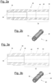
- Fig. 2a shows the first tensioning block 28 in cross-section.
- the inner thread 30 is seen to the left of Fig. 2a and extends over about a little less than 50% of the entire length of the first tensioning block 28.
- the remaining longitudinal section 42 of the first tensioning block 28 does not have an inner thread, so that the threaded bolt 24 inserted into the first tensioning block 28 inside this longitudinal section 42 is free to provide the desired pretension.
- the groove 40 is arranged in the longitudinal section 42, relatively close to the contact surface 34. The bottom of the groove 40 provides an outer surface 44 about which a tensioning element 38 can be guided.
- FIG. 2b The perspective view of Fig. 2b clearly shows the groove 40 and the hexagon head 32 of the first tensioning block 28.
- Figs. 3a and 3b show another tensioning block 28 having a hexagon head 32, an inner thread 30 as well as a longitudinal section 42 similar to the tensioning block 28 of Figs. 2a and 2b .
- the tensioning block 28 of Figs. 3a and 3b has two grooves 40 arranged side by side, so that two tensioning elements 38 can be connected, in particular to obtain crosswise tensioning.
- FIGs. 4 to 7 illustrate how the method can be applied to manipulate a shape and/or a position of wind turbine rotor blade shell members. Each figure shows a wind turbine rotor blade root section seen from a hub.
- a second wind turbine rotor blade shell member 46 namely a second half shell, is placed on top of a first wind turbine rotor blade shell member 10, a half shell as well. It is assumed that both wind turbine rotor blade shell members 10, 46 had initially been connected to one another with improper alignment, so that in an area indicated by two arrows 50, the wind turbine rotor blade had an "overbite". An adhesive provided between both wind turbine rotor blade shell members 10, 46 at the relevant section with the overbite has been removed.
- the first wind turbine rotor blade shell member 10 comprises two first inserts 18. To each of these first inserts 18, a first tensioning block 28 is mounted.
- the second wind turbine rotor blade shell member 46 comprises two second inserts 48 to each of which is mounted a second tensioning block 52.
- the first inserts 18 and the second inserts 48, as well as possibly many more inserts of the wind turbine rotor blade shell members not shown in the figure, are arranged on a circle having a centre 54.
- a tensioning element 38 in the form of a tensioning belt is guided about both first tensioning blocks 28 and both second tensioning blocks 52 such that the lateral forces applied by the tensioning element 38 to the tensioning blocks 28, 52 are aligned essentially in a radial direction with regard to the circle.
- the manipulating forces applied to the respective tensioning blocks 28, 52 are transferred to the wind turbine rotor blade shell members 10, 46, in particular so that the second wind turbine rotor blade shell member 46 will be properly aligned with reference to the first wind turbine rotor blade shell member 10, and vice versa.
- first inserts 18 and the second inserts 48 are arranged close to a connection plane 56 between both wind turbine rotor blade shell members.
- the connection plane 56 is aligned substantially horizontally.
- FIG. 5 two similar wind turbine rotor blade shell members 10, 46 are shown, also having a connection plane 56 and first inserts 18 and second inserts 48 arranged on a circle with a centre 54. Also similar to the situation of Fig. 4 , to each of these first and second inserts 18, 48, a respective first or second tensioning block 28, 52 is mounted to. In contrast to Fig. 4 , however, the first inserts 18 are arranged at a lowermost position of the first wind turbine rotor blade shell member 10, and the second inserts 48 are arranged at a topmost position of the second wind turbine rotor blade shell member 46, such that the tensioning element 38 guided around the corresponding first and second tensioning blocks 28, 52 is arranged essentially vertically. Applying the lateral manipulating forces by means of the tensioning element 38 will therefore press the improperly connected edges of the wind turbine rotor blade shell member 10, 46 against each other, as illustrated by arrows 50.
- FIG. 6 shows another application of the method to a single, first wind turbine rotor blade shell member 10.
- This first wind turbine rotor blade shell member 10 may also be a wind turbine rotor blade half shell. It comprises a plurality of inserts 18 arranged on a circle.
- the wind turbine rotor blade shell member 10 comprises a first insert 18 with a threaded bolt 24 to which a first tensioning block 28 is mounted to.
- the wind turbine rotor blade shell member 10 comprises a second insert 48 with a threaded bolt 24 to which a second tensioning block 52 is mounted to.
- a tensioning element 38 is connected to the first tensioning block 28 and to the second tensioning block 52 and applies lateral manipulating forces to the tensioning blocks 28, 52. These lateral manipulating forces may be used to prevent a deformation of the first wind turbine rotor blade shell member 10 during storage, and is thus used to maintain a desired shape of the first wind turbine rotor blade shell member 10.
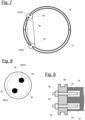
- FIG. 7 another pair of a first wind turbine rotor blade shell member 10 and a second wind turbine rotor blade shell member 46 arranged on top of the first wind turbine rotor blade shell member 10 is shown.
- the first wind turbine rotor blade shell member 10 comprises two first inserts 18 to each of which a first tensioning block 28 is mounted to.
- the second wind turbine rotor blade shell member 46 comprises two second inserts 48, to each of which a second tensioning block 52 is mounted to.
- a deflector disk 58 larger than the first tensioning blocks 28 is pushed onto the two first tensioning blocks 28.
- a similar deflector disk 58 is pushed onto the two second tensioning blocks 52.
- a tensioning element 38 is guided around both deflector disks 58, so that the lateral manipulating forces are applied to the respective first and second tensioning blocks 28, 52 via the deflector disks 58.
- Fig. 8 shows an enlarged view of the deflector disk 58 of Fig. 7 .
- the deflector disk 58 is a thick, circular disc having a circumferential groove 60 and two receiving portions 62 each receiving one of the respective first or second tensioning blocks 28, 52.
- Another option to distribute the lateral manipulating forces of the tensioning element 38 to the respective inserts 18, 48 is to use one larger tensioning block 64 mounted to the respective wind turbine rotor blade shell member 10, 46 by means of two or more inserts 18, 48 and two or more threaded bolts 24.
- These larger tensioning blocks 64 may be shaped for example similar to the deflector disks 58 and would be pressed against the two respective inserts 18, 48 by the respective screw connections.
- Fig. 9 shows an example of such a larger tensioning block 64 in a side view.
- the larger tensioning block 64 is mounted to two first inserts 18 by means of two threaded bolts 24 each guided through a through-hole in the large tensioning block 64 and pretensioned with a nut 66.
- the deflector disk 28 and larger tensioning block 64 ensure an even load transfer to both threaded bolts 24 or inserts 18, 48, especially if the tensioning element 38 does not run through the center of the rotor blade cross section.
- Fig. 10 shows another first tensioning block 28 mounted to a first insert 18 with a threaded bolt 24 which is formed integrally with the first tensioning block 28.
- the threaded bolt 24 is screwed into a first insert 18.
- the first tensioning block 28 is provided with a ring-shaped element 68 having a groove 40 and an outer surface 44.
- the ring-shaped element 68 is rotatably mounted to the first tensioning block 28.
- FIG. 11 still another first tensioning block 28 is shown mounted to a wind turbine rotor blade shell member 10 by means of a threaded bolt 24 having an outer thread 36.
- the outer thread 36 is guided through a through-hole of the tensioning block 28 and fixed with a threaded nut 66.
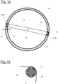
- Fig. 12 shows another example for using the method to correct an "overbite", similar to the arrangement of Fig. 4 .
- two first tensioning blocks 28 are mounted to two first inserts 18 of the first wind turbine rotor blade shell member 10
- two second tensioning blocks 52 are mounted to two second inserts 48 of the second wind turbine rotor blade shell member 46.
- Each of the tensioning blocks 28, 52 is provided with a ring-shaped element 68 having a groove 40 and an outer surface 44 and rotatably mounted to the respective tensioning block 28, 52, as has been explained with reference to Fig. 10 .
- Fig. 13 shows an enlarged cross-sectional view of the first tensioning block 28 of Fig. 12 (area labelled "A").
- a tensioning element in the form of a tensioning belt 38 is guided around the outer surface 44.
- Fig. 14 shows another arrangement of first and second wind turbine rotor blade shell members 10, 46 similar to the situation of Fig. 7 .
- Three first tensioning blocks 28 are mounted to three first inserts 18 of the first wind turbine rotor blade shell member 10; three second tensioning blocks 52 are mounted to three second inserts 48 of the second wind turbine rotor blade shell member 46.
- a tensioning element 38 in the form of a tensioning belt is connecting the first and second tensioning blocks 28, 52 in a zigzag-pattern.
- a first end 74 of the tensioning element 38 is connected to a first tensioning block 28, the opposite second end 76 of the tensioning element 38 is connected to a second tensioning block 52.
- Intermediate portions 82 of the tensioning element 38 are connected to the remaining tensioning blocks 28, 52.
- the first end 74 and the second end 76 of the tensioning element 38 each comprise a hook 78 which is hooked in a lug 80 formed on the respective tensioning block 28, 52.
- Fig. 15b shows how the intermediate portions 82 of the tensioning element 38 shown in Fig. 14 can be connected to the remaining tensioning blocks 28, 52.
- These tensioning blocks 28, 52 are provided with a lug 80 as well, and the respective intermediate portions 82 of the tensioning element 38 are guided through the lugs 80. To the left of Fig. 15b , this is shown in cross-section, to the right in a side view.
- Fig. 15c shows another way to connect the intermediate portions 82 of the tensioning element 38 shown in Fig. 14 to the remaining tensioning blocks 28, 52.
- the tensioning block 28, 52 is provided with a ring-shaped element 68 rotatably mounted to a core section 70 of the tensioning block 28, 52 with a roller bearing 72.
- the ring-shaped element 68 is provided with a lug 80 through which an intermediate section 82 of the tensioning element 38 is guided.
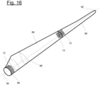
- Fig. 16 shows a wind turbine rotor blade 84 in a perspective, schematic view. It comprises a first longitudinal section 86 including a wind turbine rotor blade root 88 and a second longitudinal section 90 including a wind turbine rotor blade tip 92. Both longitudinal sections 86, 90 have a common longitudinal axis 94.
- the wind turbine rotor blade 84 also has an aerodynamic profile 96, whereas it is circular at the wind turbine rotor blade root 88.
- the first longitudinal section 86 and the second longitudinal section 90 each comprise one or more wind turbine rotor blade shell members, such as a pressure-side half shell and a suction-side half shell.
- the first longitudinal section 86 has a connection section 12 at the wind turbine rotor blade root 88.
- This connection section 12 is adapted to be fastened to a wind turbine rotor blade hub (not shown).
- the first longitudinal section 86 has another connection section 12 adapted to be fastened to the longitudinal section 90.
- the second longitudinal section 90 has a connection section 12 at its end away from the wind turbine rotor blade tip 92.
- This connection section 12 is adapted to be fastened to the first longitudinal section 86.
- connection sections 12 comprises a combination of inserts and/or threaded bolts, which are indicated in the Fig. 16 schematically only.
Landscapes
- Engineering & Computer Science (AREA)
- Life Sciences & Earth Sciences (AREA)
- Sustainable Development (AREA)
- Sustainable Energy (AREA)
- Chemical & Material Sciences (AREA)
- Combustion & Propulsion (AREA)
- Mechanical Engineering (AREA)
- General Engineering & Computer Science (AREA)
- Wind Motors (AREA)
Abstract
• providing a tensioning block having a contact surface,
• mounting the tensioning block to the wind turbine rotor blade shell member with a threaded bolt which is screwed into the insert and pretensioned such that the contact surface of the tensioning block is pressed against the connection surface of the insert with a pretensioning force,
• applying a lateral manipulating force to the tensioning block,
• wherein the pretensioning force is selected such that between the connection surface of the insert and the contact surface of the tensioning block, an interference fit is obtained strong enough to transfer the lateral manipulating force to the wind turbine rotor blade shell member.
Description
- The invention relates to a method for manipulating a shape and/or a position of a first wind turbine rotor blade shell member.
- Over the last decades, wind turbine rotor blades have continued to grow in size, making it more difficult to handle the wind turbine rotor blades and wind turbine rotor blade elements during production and transport. Whenever it becomes necessary to bring or maintain a wind turbine rotor blade shell member exactly in a desired position and/or shape, this may require applying substantial forces, which is difficult due to the complex shape of the wind turbine rotor blade shell members, and always includes a risk to damage the wind turbine rotor blade shell member's structure.
- This is particularly true when trying to repair a wind turbine rotor blade initially assembled with non-perfect alignment of its wind turbine rotor blade shell members, in particular half shells, sometimes referred to as a wind turbine rotor blade having an "overbite." Although such production faults are rare, it is highly desirable to find a suitable way to repair such wind turbine rotor blades, because in the alternative, one may have to discard the entire wind turbine rotor blade.
- Another issue that may arise in particular for large wind turbine rotor blades that undergo extended periods of storage is a slight deviation of their desired shape often referred to as "ovalization". Wind turbine rotor blades deviating from their desired, e.g. circular shape may cause problems when mounting the wind turbine rotor blade to a hub, or when in operation. For example, a pitch bearing may experience excessive wear.
- Departing therefrom, it is an object of the invention to provide a method for manipulating a shape and/or a position of a wind turbine rotor blade shell member.
- This object is solved by the method of claim 1. Advantageous aspects are given in the dependent claims.
- The method is for manipulating a shape and/or a position of a first wind turbine rotor blade shell member, wherein the first wind turbine rotor blade shell member has a connection section and a first insert having a connection surface and being arranged in the connection section, the first insert being adapted to be screw-connected to another element of a wind turbine rotor, the method comprising the following steps:
- providing a first tensioning block having a contact surface,
- mounting the first tensioning block to the first wind turbine rotor blade shell member with a threaded bolt which is screwed into the first insert and pretensioned such that the contact surface of the first tensioning block is pressed against the connection surface of the first insert with a pretensioning force,
- applying a lateral manipulating force to the first tensioning block,
- wherein the pretensioning force is selected such that between the connection surface of the first insert and the contact surface of the first tensioning block, an interference fit is obtained strong enough to transfer the lateral manipulating force to the first wind turbine rotor blade shell member.
- The wind turbine rotor may have a horizontal axis. The first wind turbine rotor blade shell member may be a wind turbine rotor blade half shell or another element of a wind turbine rotor blade comprising two or more parts connected with each other to form the entire rotor blade shell. However, the first wind turbine rotor blade shell member may also refer to a wind turbine rotor blade shell in its entirety, either when manufactured in one piece or when having been firmly assembled from two or more parts manufactured separately. The first wind turbine rotor blade shell member may extend over the entire length of the wind turbine rotor blade, from a root to a tip.
- However, the first wind turbine rotor blade shell member may also be a longitudinal segment of a wind turbine rotor blade shell member or of an entire wind turbine rotor blade shell.
- The term "connection section" refers to a section of the first wind turbine rotor blade shell member adapted to be connected to another element of a wind turbine rotor. This other element may be, for example, a wind turbine rotor hub or an extender placed between a wind turbine rotor blade root and a wind turbine rotor hub. The other element may also be another element of a wind turbine rotor blade, in particular when the wind turbine rotor blade is assembled from two or more longitudinal segments. In this case, the connection section may be an end section of a first longitudinal segment of a rotor blade shell member facing another longitudinal segment of the same wind turbine rotor blade shell member. No matter to which other element of a wind turbine rotor the first wind turbine rotor blade shell member is to be connected to, the connection surface of the first insert, which is arranged in the connection section, will be facing the other element of the wind turbine rotor.
- The first insert has an inner thread into which the threaded bolt can be screwed into. In particular, the first insert may be a sleeve having a circular, circumferential outer surface. However, this is not mandatory, the first insert may also have another cross-sectional shape. The cross-sectional shape may vary or may be constant along a longitudinal direction of the first insert. The first insert may be rotationally symmetrical. In particular, the first insert may be made of a metal such as steel.
- In accordance with the invention, a first tensioning block is provided and mounted to the first wind turbine rotor blade shell member. As will be discussed later, the first tensioning block need not to be block-shaped, in fact it may have any other shape as long as the same provides a contact surface suitable to be pressed against the connection surface of the first insert when the first tensioning block is mounted to the first wind turbine rotor blade shell member by means of the threaded bolt. The first tensioning block is mounted to the first wind turbine rotor blade shell member with a threaded bolt which is screwed into the first insert. The outer end or section of the threaded bolt not screwed into the first insert is connected to (or formed integrally with) the first tensioning block.
- When prestressing the threaded bolt, the contact surface of the first tensioning block is pressed against the connection surface of the first insert with a pretensioning force. After having mounted the first tensioning block in this manner, it is firmly attached to the first wind turbine rotor blade shell member, and between the connection surface of the first insert and the contact surface of the first tensioning block, an interference fit is obtained. The strength of the interference fit depends on the pretensioning force. The pretensioning force is selected such that the interference fit is strong enough to transfer the lateral manipulating force applied to the first tensioning block. Applying a force to the first tensioning block in a lateral direction means in a direction at an angle with reference to a longitudinal axis of the first insert and/or its inner thread. The angle may be essentially a right angle, however, any manipulating forces deviating therefrom by 60° or less, in particular by 30° or less, may be considered lateral as well.
- An important advantage of the inventive method is that the lateral manipulating force is transferred to the first wind turbine rotor blade shell member through the interference fit between the connection surface of the first insert and the contact surface of the first tensioning block. This eliminates a risk to cause any structural damage to the first wind turbine rotor blade shell member, to the embedded insert or to the threaded bolt. In particular, the threaded bolt and the inner thread of the first insert will not receive substantial loads deviating from their longitudinal directions. As a result, substantial lateral forces may be applied to the first wind turbine rotor blade shell member without causing any damage.
- At the same time, the method is particularly easy to carry out and does not require any complex parts or complicated procedures. This is true in particular when comparing the inventive method to other conceivable approaches for transferring lateral forces to the first wind turbine rotor blade shell member, such as by attaching flexible or rigid belts or beams to an outer surface of the wind turbine rotor blade shell member.
- In an aspect, the method is used for manipulating a shape and/or a position of a first wind turbine rotor blade shell member with reference to a second wind turbine rotor blade shell member, wherein the second wind turbine rotor blade shell member has a connection section and a second insert having a connection surface and being arranged in the connection section, the second insert being adapted to be screw-connected to said other element of a wind turbine rotor, and the method comprises the following additional steps:
- providing a second tensioning block having a contact surface,
- mounting the second tensioning block to the second wind turbine rotor blade shell member with a threaded bolt which is screwed into the second insert and pretensioned such that the contact surface of the second tensioning block is pressed against the connection surface of the second insert with a pretensioning force,
- applying a lateral manipulating force to the second tensioning block,
- wherein the pretensioning force applied to the threaded bolt screwed into the second insert is selected such that between the connection surface of the second insert and the second tensioning block, an interference fit is obtained strong enough to transfer the lateral manipulating force applied to the second tensioning block to the second wind turbine rotor blade shell member,
- wherein the lateral manipulating forces are applied by means of a tensioning element connected to the first tensioning block and to the second tensioning block.
- In other words, the method of claim 1 is applied in combination with a second wind turbine rotor blade shell member having a second insert, and a second tensioning block is mounted to the second wind turbine rotor blade shell member in the same manner as explained above with regard to the first tensioning block and the first wind turbine rotor blade shell member. Further, to both tensioning blocks, lateral manipulating forces are applied by means of a tensioning element connected to both tensioning blocks. The tensioning element may in particular comprise a tensioning belt guided around or otherwise connected to both tensioning blocks. The lateral manipulating force applied to the first wind turbine rotor blade shell member may be a counterforce to the lateral manipulating force applied to the second tensioning block. Through the lateral manipulating forces, the relative position of both wind turbine rotor blade shell members can be modified or maintained. It is possible as well to modify or maintain a shape of one or both of the wind turbine rotor blade shell members. Essentially the same methods can be carried out with a single wind turbine rotor blade shell member comprising the first insert as well as the second insert. Then, by mounting two tensioning blocks and applying lateral forces with the tensioning element, a specific shape of the single wind turbine rotor blade shell member can be modified or maintained.
- In an aspect, the threaded bolt screwed into the respective insert has a design pretension that is to be applied when this insert is being screw-connected to said respective other element of a wind turbine rotor by means of the threaded bolt, and the pretensioning force applied by the respective tensioning block is selected in a range of 50 % to 100 % of the design pretension. In this range, a strong interference fit is obtained without running the risk to exceed the relevant design loads.
- In an aspect, the first wind turbine rotor blade shell member and the second wind turbine rotor blade shell member comprise a plurality of inserts disposed on a circle, and the tensioning blocks and the tensioning element are arranged such that the lateral forces are applied substantially in a radial direction with reference to the circle. Then, the lateral forces are well suited to correct a misalignment or deformation in a radial direction.
- In an aspect, the method is applied to repair a wind turbine rotor blade comprising the first wind turbine rotor blade shell member and the second wind turbine rotor blade shell member, wherein the lateral manipulating forces are applied until an end position with proper alignment of both wind turbine rotor blade shell members is obtained. This aspect addresses in particular the issue of two wind turbine rotor blade half shells having an "overbite". In particular, when two such misaligned wind turbine rotor blade half shells had already been connected to each other, it may become necessary to remove an adhesive between both half shells, that is along the leading edge and/or the trailing edge of the wind turbine rotor blade. Once the adhesive has been removed, the inventive method can be applied to obtain the desired alignment.
- In an aspect, the wind turbine rotor blade shell members are connected to each other in the end position by means of an adhesive. Once the adhesive has cured, the wind turbine rotor blade shell members are fixed in their desired position relative to each other and the lateral manipulating forces need no longer be applied.
- In an aspect, the method is applied to prevent a deformation of the first wind turbine rotor blade shell member and/or of the second wind turbine rotor blade shell member, wherein the lateral manipulating force applied to the respective wind turbine rotor blade shell member is applied such that the respective wind turbine rotor blade shell member is held in a desired shape. A typical deformation that may be counteracted by the inventive method is the so-called ovalization of a wind turbine rotor blade that may occur after having removed the wind turbine rotor blade shell members out of their manufacturing moulds and before providing the wind turbine rotor blade with additional stiffening members, for example a stiffening rip or plate, or a steel ring of a pitch bearing.
- In an aspect, the first tensioning block and/or the second tensioning block has an axially symmetrical shape. For example, one may use a sleeve or a thick, circular disc or plate. The respective tensioning block may comprise a central tapped blind hole or a through-hole with or without an inner threat.
- In an aspect, the first insert and/or the second insert is embedded in a laminate of the respective wind turbine rotor blade shell member. Then, the respective insert is fixedly connected in the wind turbine rotor blade shell member. In an alternative, the inserts can be mounted in bores of the wind turbine rotor blade shell members by means of an adhesive.
- In an aspect, the first tensioning block and/or the second tensioning block is mounted to the respective wind turbine rotor blade shell member by means of an outer thread of the respective threaded bolt, wherein the outer thread is guided through a through-hole of the respective tensioning block and fixed with a threaded nut. This is an easy yet efficient way to connect the tensioning block to the bolt. The desired pretension can be applied by fastening the nut to the desired level.
- In an aspect, the first tensioning block and/or the second tensioning block is mounted to the respective wind turbine rotor blade shell member by means of an outer thread of the respective threaded bolt, wherein the outer thread is screwed into an inner thread of the respective tensioning block. In this aspect, no additional nut is needed to mount the tensioning block. The threaded bolt is pretensioned by turning the tensioning block. To this end, the tensioning block may comprise a hexagon head or another specific contour making it easy to apply a fastening tool.
- The inner thread may be formed in the respective tensioning block in a distance from the contact surface of the respective tensioning block, so that a section of the threaded bolt having a sufficient length (wherein this section of the threaded bolt may or may not have an outer thread) remains free and provides extensibility for the desired pretension.
- In an aspect, the first tensioning block and/or the second tensioning block is mounted to the respective wind turbine rotor blade shell member by at least one additional threaded bolt screwed into an additional insert of the respective wind turbine rotor blade shell member. Thereby, the additional threaded bolt can be pretensioned as described above for the threaded bolt screwed into the first insert, so that an even stronger interference fit is obtained. In this way, particularly strong lateral manipulating forces can be applied without running a risk to damage the respective wind turbine rotor blade shell members' structure.
- In an aspect, the first tensioning block and/or the second tensioning block and the respective threaded bolt are manufactured in one piece or are firmly assembled. In this aspect, no separate threaded bolts are needed to mount the respective tensioning blocks to the wind turbine rotor blade shell members.
- In an aspect, the first tensioning block and/or the second tensioning block has a longitudinal section with an outer surface adapted to receive a connecting section of the tensioning element. This outer surface, for example, can be provided by a circumferential groove of the tensioning block. This makes it easy to maintain a desired position of the tensioning element.
- In an aspect, the outer surface is rotatably mounted to the respective tensioning block. For example, the outer surface can be an outer surface of a ring-shaped element connected to the remainder of the respective tensioning block with a roller bearing. Thereby, the respective lateral manipulating force will be applied to the tensioning block in a smooth and symmetrical manner, in particular when using a tensioning belt as tensioning element and guiding the same around several tensioning blocks.
- In the following, the invention is explained in greater detail with reference to embodiments shown in drawings. The figures show:
- Fig. 1
- a first tensioning block mounted to a first wind turbine rotor blade shell member in a schematic drawing,
- Fig. 2
- the tensioning block shown in
Fig. 1 in cross-section along its longitudinal axis, - Fig. 3
- the tensioning block of
Figs. 1 and2 in a perspective view, - Fig. 4
- two wind turbine rotor blade shell members with four tensioning blocks and a tensioning element in a schematic view,
- Fig. 5
- two other wind turbine rotor blade shell members with four tensioning blocks and a tensioning element mounted thereto in a schematic view,
- Fig. 6
- a wind turbine rotor blade shell member with two tensioning blocks mounted thereto connected by a tensioning element in a schematic view,
- Fig. 7
- two wind turbine rotor blade shell members to each of which a tensioning block is fastened by two threaded bolts in a schematic view,
- Fig. 8
- one of the tensioning blocks of
Fig. 7 in an enlarged view, and - Fig. 9
- another tensioning block in a schematic, sectional view
- Fig. 10
- a tensioning block with a rotatable outer surface in a schematic drawing,
- Fig. 11
- a tensioning block mounted with a nut in a schematic drawing,
- Fig. 12
- two wind turbine rotor blade shell members with four tensioning blocks and a tensioning element in a schematic view,
- Fig. 13
- an enlarged, cross-sectional view of a tensioning block of
Fig. 12 , - Fig. 14
- two wind turbine rotor blade shell members with six tensioning blocks and a tensioning element in a schematic view,
- Fig. 15a
- a tensioning element with a hook mounted to a tensioning block with a lug in a schematic view,
- Fig. 15b
- a tensioning block mounted to a tensioning block with a lug in two schematic views,
- Fig. 15c
- another tensioning block mounted to a tensioning element in a schematic view, and
- Fig. 16
- a wind turbine rotor blade in a perspective, schematic view.
-
Fig. 1 shows a first wind turbine rotorblade shell member 10, wherein only aconnection section 12 thereof is included in the view. Theconnection section 12 comprises alaminate 14 of a fibre-reinforced composite material having alaminate thickness 16. Afirst insert 18 is embedded in thelaminate 14. Thefirst insert 18 is an axially symmetrical sleeve having acontact surface 20 and aninner thread 22. Thefirst insert 18 is adapted to be screw-connected to another element of a wind turbine rotor, which is not shown in the drawing, and may for example be a wind turbine rotor hub. In this case, theconnection section 12 is a root section of the first wind turbine rotorblade shell member 10. - A threaded
bolt 24 has anouter thread 26 and is screwed into theinner thread 22 of thefirst insert 18. - To the left of
Fig. 1 , one can see afirst tensioning block 28 that is sleeve-shaped as well. It comprises aninner thread 30 and ahexagon head 32. At the opposite end, thefirst tensioning block 28 comprises acontact surface 34 abutting theconnection surface 20 of thefirst insert 18. - The threaded
bolt 24 is pretensioned by screwing thefirst tensioning block 28 onto the threadedbolt 24 by means of a suitable tool connecting to thehexagon head 32. Thereby, thecontact surface 34 is pressed against theconnection surface 20 with a pretensioning force. - After having mounted the
first tensioning block 28 to thefirst insert 18 as described, a lateral manipulating force is applied to thefirst tensioning block 28 with atensioning element 38, as illustrated by the arrow pointing downwards inFig. 1 . Thetensioning element 38 may be a tensioning belt which is guided around thefirst tensioning block 28 in a longitudinal section thereof having acircumferential groove 40. - By means of the pretension applied to the threaded
bolt 24, an interference fit between theconnection surface 20 and thecontact surface 34 is obtained, strong enough to transfer the lateral manipulating force applied withtensioning element 38 to the first wind turbine rotorblade shell member 10. - The
first insert 18, the threadedbolt 24 and thefirst tensioning block 28 each have a longitudinal axis, wherein these axes are all aligned and correspond to a longitudinal direction of the first wind turbine rotorblade shell member 10. -
Fig. 2a shows thefirst tensioning block 28 in cross-section. Theinner thread 30 is seen to the left ofFig. 2a and extends over about a little less than 50% of the entire length of thefirst tensioning block 28. The remaininglongitudinal section 42 of thefirst tensioning block 28 does not have an inner thread, so that the threadedbolt 24 inserted into thefirst tensioning block 28 inside thislongitudinal section 42 is free to provide the desired pretension. Thegroove 40 is arranged in thelongitudinal section 42, relatively close to thecontact surface 34. The bottom of thegroove 40 provides anouter surface 44 about which atensioning element 38 can be guided. - The perspective view of
Fig. 2b clearly shows thegroove 40 and thehexagon head 32 of thefirst tensioning block 28. -
Figs. 3a and 3b show anothertensioning block 28 having ahexagon head 32, aninner thread 30 as well as alongitudinal section 42 similar to thetensioning block 28 ofFigs. 2a and 2b . Thetensioning block 28 ofFigs. 3a and 3b has twogrooves 40 arranged side by side, so that two tensioningelements 38 can be connected, in particular to obtain crosswise tensioning. -
Figs. 4 to 7 illustrate how the method can be applied to manipulate a shape and/or a position of wind turbine rotor blade shell members. Each figure shows a wind turbine rotor blade root section seen from a hub. - In
Fig. 4 , a second wind turbine rotorblade shell member 46, namely a second half shell, is placed on top of a first wind turbine rotorblade shell member 10, a half shell as well. It is assumed that both wind turbine rotorblade shell members arrows 50, the wind turbine rotor blade had an "overbite". An adhesive provided between both wind turbine rotorblade shell members blade shell member 10 comprises twofirst inserts 18. To each of thesefirst inserts 18, afirst tensioning block 28 is mounted. - The second wind turbine rotor
blade shell member 46 comprises two second inserts 48 to each of which is mounted a second tensioning block 52. The first inserts 18 and the second inserts 48, as well as possibly many more inserts of the wind turbine rotor blade shell members not shown in the figure, are arranged on a circle having acentre 54. Atensioning element 38 in the form of a tensioning belt is guided about both first tensioning blocks 28 and both second tensioning blocks 52 such that the lateral forces applied by thetensioning element 38 to the tensioning blocks 28, 52 are aligned essentially in a radial direction with regard to the circle. - The manipulating forces applied to the respective tensioning blocks 28, 52 are transferred to the wind turbine rotor
blade shell members blade shell member 46 will be properly aligned with reference to the first wind turbine rotorblade shell member 10, and vice versa. - In
Fig. 4 , thefirst inserts 18 and the second inserts 48 are arranged close to aconnection plane 56 between both wind turbine rotor blade shell members. Theconnection plane 56 is aligned substantially horizontally. - In
Fig. 5 , two similar wind turbine rotorblade shell members connection plane 56 andfirst inserts 18 and second inserts 48 arranged on a circle with acentre 54. Also similar to the situation ofFig. 4 , to each of these first andsecond inserts 18, 48, a respective first orsecond tensioning block 28, 52 is mounted to. In contrast toFig. 4 , however, thefirst inserts 18 are arranged at a lowermost position of the first wind turbine rotorblade shell member 10, and the second inserts 48 are arranged at a topmost position of the second wind turbine rotorblade shell member 46, such that thetensioning element 38 guided around the corresponding first and second tensioning blocks 28, 52 is arranged essentially vertically. Applying the lateral manipulating forces by means of thetensioning element 38 will therefore press the improperly connected edges of the wind turbine rotorblade shell member arrows 50. -
Fig. 6 shows another application of the method to a single, first wind turbine rotorblade shell member 10. This first wind turbine rotorblade shell member 10 may also be a wind turbine rotor blade half shell. It comprises a plurality ofinserts 18 arranged on a circle. At the top left, the wind turbine rotorblade shell member 10 comprises afirst insert 18 with a threadedbolt 24 to which afirst tensioning block 28 is mounted to. To the top right, the wind turbine rotorblade shell member 10 comprises a second insert 48 with a threadedbolt 24 to which a second tensioning block 52 is mounted to. Atensioning element 38 is connected to thefirst tensioning block 28 and to the second tensioning block 52 and applies lateral manipulating forces to the tensioning blocks 28, 52. These lateral manipulating forces may be used to prevent a deformation of the first wind turbine rotorblade shell member 10 during storage, and is thus used to maintain a desired shape of the first wind turbine rotorblade shell member 10. - In
Fig. 7 , another pair of a first wind turbine rotorblade shell member 10 and a second wind turbine rotorblade shell member 46 arranged on top of the first wind turbine rotorblade shell member 10 is shown. The first wind turbine rotorblade shell member 10 comprises twofirst inserts 18 to each of which afirst tensioning block 28 is mounted to. The second wind turbine rotorblade shell member 46 comprises two second inserts 48, to each of which a second tensioning block 52 is mounted to. In this embodiment, adeflector disk 58 larger than the first tensioning blocks 28 is pushed onto the two first tensioning blocks 28. Asimilar deflector disk 58 is pushed onto the two second tensioning blocks 52. Atensioning element 38 is guided around bothdeflector disks 58, so that the lateral manipulating forces are applied to the respective first and second tensioning blocks 28, 52 via thedeflector disks 58. -
Fig. 8 shows an enlarged view of thedeflector disk 58 ofFig. 7 . Thedeflector disk 58 is a thick, circular disc having acircumferential groove 60 and two receivingportions 62 each receiving one of the respective first or second tensioning blocks 28, 52. - Another option to distribute the lateral manipulating forces of the
tensioning element 38 to therespective inserts 18, 48 is to use onelarger tensioning block 64 mounted to the respective wind turbine rotorblade shell member more inserts 18, 48 and two or more threadedbolts 24. These larger tensioning blocks 64 may be shaped for example similar to thedeflector disks 58 and would be pressed against the tworespective inserts 18, 48 by the respective screw connections. -
Fig. 9 shows an example of such alarger tensioning block 64 in a side view. One recognizes thecircumferential groove 60 adapted to receive thetensioning element 38. Thelarger tensioning block 64 is mounted to twofirst inserts 18 by means of two threadedbolts 24 each guided through a through-hole in thelarge tensioning block 64 and pretensioned with anut 66. - The
deflector disk 28 andlarger tensioning block 64 ensure an even load transfer to both threadedbolts 24 or inserts 18, 48, especially if thetensioning element 38 does not run through the center of the rotor blade cross section. -
Fig. 10 shows anotherfirst tensioning block 28 mounted to afirst insert 18 with a threadedbolt 24 which is formed integrally with thefirst tensioning block 28. The threadedbolt 24 is screwed into afirst insert 18. Thefirst tensioning block 28 is provided with a ring-shapedelement 68 having agroove 40 and anouter surface 44. The ring-shapedelement 68 is rotatably mounted to thefirst tensioning block 28. - In
Fig. 11 , still anotherfirst tensioning block 28 is shown mounted to a wind turbine rotorblade shell member 10 by means of a threadedbolt 24 having anouter thread 36. Theouter thread 36 is guided through a through-hole of thetensioning block 28 and fixed with a threadednut 66. -
Fig. 12 shows another example for using the method to correct an "overbite", similar to the arrangement ofFig. 4 . As inFig. 4 , two first tensioning blocks 28 are mounted to twofirst inserts 18 of the first wind turbine rotorblade shell member 10, and two second tensioning blocks 52 are mounted to two second inserts 48 of the second wind turbine rotorblade shell member 46. Each of the tensioning blocks 28, 52 is provided with a ring-shapedelement 68 having agroove 40 and anouter surface 44 and rotatably mounted to therespective tensioning block 28, 52, as has been explained with reference toFig. 10 . -
Fig. 13 shows an enlarged cross-sectional view of thefirst tensioning block 28 ofFig. 12 (area labelled "A"). One can see the ring-shapedelement 68 connected to acore section 70 of thefirst tensioning block 28 via aroller bearing 72. A tensioning element in the form of atensioning belt 38 is guided around theouter surface 44. -
Fig. 14 shows another arrangement of first and second wind turbine rotorblade shell members Fig. 7 . Three first tensioning blocks 28 are mounted to threefirst inserts 18 of the first wind turbine rotorblade shell member 10; three second tensioning blocks 52 are mounted to three second inserts 48 of the second wind turbine rotorblade shell member 46. Atensioning element 38 in the form of a tensioning belt is connecting the first and second tensioning blocks 28, 52 in a zigzag-pattern. Afirst end 74 of thetensioning element 38 is connected to afirst tensioning block 28, the oppositesecond end 76 of thetensioning element 38 is connected to a second tensioning block 52.Intermediate portions 82 of thetensioning element 38 are connected to the remaining tensioning blocks 28, 52. - As is shown in
Fig. 15a , thefirst end 74 and thesecond end 76 of thetensioning element 38 each comprise ahook 78 which is hooked in alug 80 formed on therespective tensioning block 28, 52. -
Fig. 15b shows how theintermediate portions 82 of thetensioning element 38 shown inFig. 14 can be connected to the remaining tensioning blocks 28, 52. These tensioning blocks 28, 52 are provided with alug 80 as well, and the respectiveintermediate portions 82 of thetensioning element 38 are guided through thelugs 80. To the left ofFig. 15b , this is shown in cross-section, to the right in a side view. -
Fig. 15c shows another way to connect theintermediate portions 82 of thetensioning element 38 shown inFig. 14 to the remaining tensioning blocks 28, 52. In this case, thetensioning block 28, 52 is provided with a ring-shapedelement 68 rotatably mounted to acore section 70 of thetensioning block 28, 52 with aroller bearing 72. The ring-shapedelement 68 is provided with alug 80 through which anintermediate section 82 of thetensioning element 38 is guided. -
Fig. 16 shows a wind turbine rotor blade 84 in a perspective, schematic view. It comprises a firstlongitudinal section 86 including a wind turbinerotor blade root 88 and a secondlongitudinal section 90 including a wind turbinerotor blade tip 92. Bothlongitudinal sections longitudinal axis 94. The wind turbine rotor blade 84 also has anaerodynamic profile 96, whereas it is circular at the wind turbinerotor blade root 88. The firstlongitudinal section 86 and the secondlongitudinal section 90 each comprise one or more wind turbine rotor blade shell members, such as a pressure-side half shell and a suction-side half shell. - The first
longitudinal section 86 has aconnection section 12 at the wind turbinerotor blade root 88. Thisconnection section 12 is adapted to be fastened to a wind turbine rotor blade hub (not shown). At its opposite end, the firstlongitudinal section 86 has anotherconnection section 12 adapted to be fastened to thelongitudinal section 90. - The second
longitudinal section 90 has aconnection section 12 at its end away from the wind turbinerotor blade tip 92. Thisconnection section 12 is adapted to be fastened to the firstlongitudinal section 86. - Each of these
connection sections 12 comprises a combination of inserts and/or threaded bolts, which are indicated in theFig. 16 schematically only. -
- 10
- first wind turbine rotor blade shell member
- 12
- connection section
- 14
- laminate
- 16
- laminate thickness
- 18
- first insert
- 20
- connection surface
- 22
- inner thread
- 24
- threaded bolt
- 26
- outer thread
- 28
- first tensioning block
- 30
- inner thread
- 32
- hexagon head
- 34
- contact surface
- 36
- outer thread
- 38
- tensioning element
- 40
- groove
- 42
- longitudinal section
- 44
- outer surface
- 46
- second wind turbine rotor blade shell member
- 48
- second insert
- 50
- arrow
- 52
- second tensioning block
- 54
- centre
- 56
- connection plane
- 58
- deflector disk
- 60
- groove
- 62
- receiving portion
- 64
- tensioning block
- 66
- nut
- 68
- ring-shaped element
- 70
- core section
- 72
- roller bearing
- 74
- first end
- 76
- second end
- 78
- hook
- 80
- lug
- 82
- intermediate section
- 84
- wind turbine rotor blade
- 86
- first longitudinal section
- 88
- wind turbine rotor blade root
- 90
- second longitudinal section
- 92
- wind turbine rotor blade tip
- 94
- longitudinal axis
- 96
- aerodynamic profile
Claims (15)
- A method for manipulating a shape and/or a position of a first wind turbine rotor blade shell member (10), wherein the first wind turbine rotor blade shell member (10) has a connection section (12) and a first insert (18) having a connection surface (20) and being arranged in the connection section (12), the first insert (18) being adapted to be screw-connected to another element of a wind turbine rotor, the method comprising the following steps:• providing a first tensioning block (28) having a contact surface (34),• mounting the first tensioning block (28) to the first wind turbine rotor blade shell member (10) with a threaded bolt (24) which is screwed into the first insert (18) and pretensioned such that the contact surface (34) of the first tensioning block (28) is pressed against the connection surface (20) of the first insert (18) with a pretensioning force,• applying a lateral manipulating force to the first tensioning block (28),• wherein the pretensioning force is selected such that between the connection surface (20) of the first insert (18) and the contact surface (34) of the first tensioning block (28), an interference fit is obtained strong enough to transfer the lateral manipulating force to the first wind turbine rotor blade shell member (10).
- The method of claim 1 for manipulating a shape and/or a position of a first wind turbine rotor blade shell member (10) with reference to a second wind turbine rotor blade shell member (46), wherein the second wind turbine rotor blade shell member (46) has a connection section (12) and a second insert (48) having a connection surface (34) and being arranged in the connection section (12), the second insert (48) being adapted to be screw-connected to said other element of a wind turbine rotor, the method comprising the following additional steps:• providing a second tensioning block (52) having a contact surface (34),• mounting the second tensioning block (52) to the second wind turbine rotor blade shell member (46) with a threaded bolt (24) which is screwed into the second insert (48) and pretensioned such that the contact surface (34) of the second tensioning block (52) is pressed against the connection surface (20) of the second insert (48) with a pretensioning force,• applying a lateral manipulating force to the second tensioning block (52),• wherein the pretensioning force applied to the threaded bolt (24) screwed into the second insert (48) is selected such that between the connection surface (34) of the second insert (48) and the second tensioning block (52), an interference fit is obtained strong enough to transfer the lateral manipulating force applied to the second tensioning block (52) to the second wind turbine rotor blade shell member (46),• wherein the lateral manipulating forces are applied by means of a tensioning element (38) connected to the first tensioning block (28) and to the second tensioning block (52).
- The method of claim 1 or 2, wherein the threaded bolt (24) screwed into the respective insert (18, 48) has a design pretension that is to be applied when this insert (18, 48) is being screw-connected to said respective other element of a wind turbine rotor by means of the threaded bolt (24), and the pretensioning force applied by the respective tensioning block (28, 52) is selected in a range of 50 % to 100 % of the design pretension.
- The method of claim 2 or 3, wherein the first wind turbine rotor blade shell member (10) and second wind turbine rotor blade shell member (46) comprise a plurality of inserts (18, 48) disposed on a circle, and the tensioning blocks (28, 52) and the tensioning element (38) are arranged such that the lateral manipulating forces are applied substantially in a radial direction with reference to the circle.
- The method of any of the claims 2 to 4, wherein the method is applied to repair a wind turbine rotor blade comprising the first wind turbine rotor blade shell member (10) and the second wind turbine rotor blade shell member (46), wherein the lateral manipulating forces are applied until an end position with proper alignment of both wind turbine rotor blade shell members (10, 46) is obtained.
- The method of claim 5, wherein the wind turbine rotor blade shell members (10, 46) are connected to each other in the end position by means of an adhesive.
- The method of any of the claims 1 to 4, wherein the method is applied to prevent a deformation of the first wind turbine rotor blade shell member (10) and/or of the second wind turbine rotor blade shell member (46), wherein the lateral manipulating force applied to the respective wind turbine rotor blade shell member (10, 46) is applied such that the respective wind turbine rotor blade shell member (10, 46) is held in a desired shape.
- The method of any of the claims 1 to 7, wherein the first tensioning block (28) and/or the second tensioning block (52) has an axially symmetrical shape.
- The method of any of the claims 1 to 8, wherein the first insert (18) and/or the second insert (48) is embedded in a laminate (14) of the respective wind turbine rotor blade shell member (10, 46).
- The method of any of the claims 1 to 9, wherein the first tensioning block (28) and/or the second tensioning block (52) is mounted to the respective wind turbine rotor blade shell member (10, 46) by means of an outer thread (36) of the respective threaded bolt (24), wherein the outer thread (36) is guided through a through-hole of the respective tensioning block (28, 52) and fixed with a threaded nut (66).
- The method of any of the claims 1 to 9, wherein the first tensioning block (28) and/or the second tensioning block (52) is mounted to the respective wind turbine rotor blade shell member (10, 46) by means of an outer thread (36) of the respective threaded bolt (24), wherein the outer thread (36) is screwed into an inner thread (30) of the respective tensioning block (28, 52).
- The method of any of the claims 1 to 10, wherein the first tensioning block (28) and/or the second tensioning block (52) is mounted to the respective wind turbine rotor blade shell member (10, 46) by at least one additional threaded bolt (24) screwed into an additional insert of the respective wind turbine rotor blade shell member (10, 46).
- The method of any of the claims 1 to 9, wherein the first tensioning block (28) and/or the second tensioning block (52) and the respective threaded bolt (24) are manufactured in one piece or are firmly assembled.
- The method of any of the claims 1 to 13, wherein the first tensioning block (28) and/or the second tensioning block (52) has a longitudinal section (42) with an outer surface (44) adapted to receive a connecting section of the tensioning element (38).
- The method of claim 14, wherein the outer surface (44) is rotatably mounted to the respective tensioning block (28, 52).
Priority Applications (5)
| Application Number | Priority Date | Filing Date | Title |
|---|---|---|---|
| ES23178616T ES3067732T3 (en) | 2023-06-12 | 2023-06-12 | A method for manipulating a shape and/or a position of a wind turbine rotor blade shell member |
| EP23178616.1A EP4477869B1 (en) | 2023-06-12 | 2023-06-12 | A method for manipulating a shape and/or a position of a wind turbine rotor blade shell member |
| DK23178616.1T DK4477869T3 (en) | 2023-06-12 | 2023-06-12 | METHOD FOR MANIPULATING A SHAPE AND/OR A POSITION OF A WIND TURBINE ROTOR BLADE SHELL ELEMENT |
| MX2024005360A MX2024005360A (en) | 2023-06-12 | 2024-05-02 | Method for manipulating the shape and/or position of a rotor blade shell member of a wind turbine. |
| CN202410749141.7A CN119122734A (en) | 2023-06-12 | 2024-06-12 | Method for manipulating the shape and/or position of a wind turbine rotor blade shell component |
Applications Claiming Priority (1)
| Application Number | Priority Date | Filing Date | Title |
|---|---|---|---|
| EP23178616.1A EP4477869B1 (en) | 2023-06-12 | 2023-06-12 | A method for manipulating a shape and/or a position of a wind turbine rotor blade shell member |
Publications (2)
| Publication Number | Publication Date |
|---|---|
| EP4477869A1 true EP4477869A1 (en) | 2024-12-18 |
| EP4477869B1 EP4477869B1 (en) | 2026-01-28 |
Family
ID=86760499
Family Applications (1)
| Application Number | Title | Priority Date | Filing Date |
|---|---|---|---|
| EP23178616.1A Active EP4477869B1 (en) | 2023-06-12 | 2023-06-12 | A method for manipulating a shape and/or a position of a wind turbine rotor blade shell member |
Country Status (5)
| Country | Link |
|---|---|
| EP (1) | EP4477869B1 (en) |
| CN (1) | CN119122734A (en) |
| DK (1) | DK4477869T3 (en) |
| ES (1) | ES3067732T3 (en) |
| MX (1) | MX2024005360A (en) |
Citations (4)
| Publication number | Priority date | Publication date | Assignee | Title |
|---|---|---|---|---|
| EP2617990A1 (en) * | 2012-01-17 | 2013-07-24 | Alstom Wind, S.L.U. | Anti-ovalization tool for introduction into a wind turbine blade root and method of reducing ovalization of a wind turbine blade root |
| EP2674612A1 (en) * | 2012-06-11 | 2013-12-18 | Alstom Wind, S.L.U. | Blade for a wind turbine |
| US20140377072A1 (en) * | 2013-06-24 | 2014-12-25 | General Electric Company | Root stiffener for a wind turbine rotor blade |
| US20140377078A1 (en) * | 2013-06-24 | 2014-12-25 | General Electric Company | Root stiffener for a wind turbine rotor blade |
-
2023
- 2023-06-12 DK DK23178616.1T patent/DK4477869T3/en active
- 2023-06-12 ES ES23178616T patent/ES3067732T3/en active Active
- 2023-06-12 EP EP23178616.1A patent/EP4477869B1/en active Active
-
2024
- 2024-05-02 MX MX2024005360A patent/MX2024005360A/en unknown
- 2024-06-12 CN CN202410749141.7A patent/CN119122734A/en active Pending
Patent Citations (4)
| Publication number | Priority date | Publication date | Assignee | Title |
|---|---|---|---|---|
| EP2617990A1 (en) * | 2012-01-17 | 2013-07-24 | Alstom Wind, S.L.U. | Anti-ovalization tool for introduction into a wind turbine blade root and method of reducing ovalization of a wind turbine blade root |
| EP2674612A1 (en) * | 2012-06-11 | 2013-12-18 | Alstom Wind, S.L.U. | Blade for a wind turbine |
| US20140377072A1 (en) * | 2013-06-24 | 2014-12-25 | General Electric Company | Root stiffener for a wind turbine rotor blade |
| US20140377078A1 (en) * | 2013-06-24 | 2014-12-25 | General Electric Company | Root stiffener for a wind turbine rotor blade |
Also Published As
| Publication number | Publication date |
|---|---|
| EP4477869B1 (en) | 2026-01-28 |
| DK4477869T3 (en) | 2026-03-30 |
| MX2024005360A (en) | 2025-01-09 |
| CN119122734A (en) | 2024-12-13 |
| ES3067732T3 (en) | 2026-05-25 |
Similar Documents
| Publication | Publication Date | Title |
|---|---|---|
| US7980827B2 (en) | Method and connecting piece for assembling an arm, preferably a windmill arm, in sections | |
| US11994101B2 (en) | Wind turbine rotor blade, mounting sleeve and method for connecting two rotor blade segments | |
| EP1975405B1 (en) | Connection of elements of a wind turbine plant, use thereof and method | |
| US7335108B2 (en) | Composite drive shaft with captured end adapters | |
| US8425195B2 (en) | Wind turbine blade | |
| EP3108140B1 (en) | Wind turbine blade bushing system | |
| EP2238344B1 (en) | Wind turbine blade and hub assembly | |
| DE19903550C1 (en) | Blade root for propeller and rotor blades | |
| EP2558716B1 (en) | T-bolt attachment of a blade root of a wind turbine | |
| EP2920457B1 (en) | A method of manufacturing a blade element | |
| CN109733578B (en) | High-power and large-size adjustable pitch propeller hub | |
| CN103747944B (en) | Wind turbine blade with elongated fastening members in the root region thereof | |
| US20170362945A1 (en) | Blade for a Wind Turbine | |
| WO2016066162A1 (en) | Method for the production of a vehicle wheel with a connection between a wheel rim and a wheel disc | |
| CA3017660A1 (en) | Splined end fittings | |
| CN101614184A (en) | Blade insert | |
| EP4477869B1 (en) | A method for manipulating a shape and/or a position of a wind turbine rotor blade shell member | |
| EP0996825B1 (en) | Fan blade mounting | |
| EP0749385B1 (en) | An expandable spar filler block device | |
| EP4400712A1 (en) | Insert for a wind turbine rotor blade and wind turbine rotor blade | |
| WO2023169677A1 (en) | Wind turbine rotor blade and method of joining two rotor blade segments | |
| BR102024008917A2 (en) | METHOD FOR MANIPULATING A SHAPE AND/OR POSITION OF A WIND TURBINE ROTOR BLADE HOUSING COMPONENT | |
| WO2025031802A1 (en) | Method for joining two rotor blade segments of a wind turbine rotor blade as well as alignment pin | |
| DK202070054A1 (en) | A wind turbine blade assembly and a pitch bearing for a wind turbine | |
| EP3630469B1 (en) | A device and a method for interlocking core elements |
Legal Events
| Date | Code | Title | Description |
|---|---|---|---|
| PUAI | Public reference made under article 153(3) epc to a published international application that has entered the european phase |
Free format text: ORIGINAL CODE: 0009012 |
|
| STAA | Information on the status of an ep patent application or granted ep patent |
Free format text: STATUS: THE APPLICATION HAS BEEN PUBLISHED |
|
| AK | Designated contracting states |
Kind code of ref document: A1 Designated state(s): AL AT BE BG CH CY CZ DE DK EE ES FI FR GB GR HR HU IE IS IT LI LT LU LV MC ME MK MT NL NO PL PT RO RS SE SI SK SM TR |
|
| STAA | Information on the status of an ep patent application or granted ep patent |
Free format text: STATUS: REQUEST FOR EXAMINATION WAS MADE |
|
| 17P | Request for examination filed |
Effective date: 20250509 |
|
| GRAP | Despatch of communication of intention to grant a patent |
Free format text: ORIGINAL CODE: EPIDOSNIGR1 |
|
| STAA | Information on the status of an ep patent application or granted ep patent |
Free format text: STATUS: GRANT OF PATENT IS INTENDED |
|
| INTG | Intention to grant announced |
Effective date: 20250915 |
|
| GRAS | Grant fee paid |
Free format text: ORIGINAL CODE: EPIDOSNIGR3 |
|
| GRAA | (expected) grant |
Free format text: ORIGINAL CODE: 0009210 |
|
| STAA | Information on the status of an ep patent application or granted ep patent |
Free format text: STATUS: THE PATENT HAS BEEN GRANTED |
|
| AK | Designated contracting states |
Kind code of ref document: B1 Designated state(s): AL AT BE BG CH CY CZ DE DK EE ES FI FR GB GR HR HU IE IS IT LI LT LU LV MC ME MK MT NL NO PL PT RO RS SE SI SK SM TR |
|
| REG | Reference to a national code |
Ref country code: CH Ref legal event code: F10 Free format text: ST27 STATUS EVENT CODE: U-0-0-F10-F00 (AS PROVIDED BY THE NATIONAL OFFICE) Effective date: 20260128 Ref country code: GB Ref legal event code: FG4D |
|
| REG | Reference to a national code |
Ref country code: IE Ref legal event code: FG4D |
|
| REG | Reference to a national code |
Ref country code: DE Ref legal event code: R096 Ref document number: 602023011183 Country of ref document: DE |
|
| REG | Reference to a national code |
Ref country code: DK Ref legal event code: T3 Effective date: 20260326 |
|
| P01 | Opt-out of the competence of the unified patent court (upc) registered |
Free format text: CASE NUMBER: UPC_APP_0010455_4477869/2026 Effective date: 20260319 |
|
| REG | Reference to a national code |
Ref country code: ES Ref legal event code: FG2A Ref document number: 3067732 Country of ref document: ES Kind code of ref document: T3 Effective date: 20260525 |
|
| REG | Reference to a national code |
Ref country code: NL Ref legal event code: MP Effective date: 20260128 |
|
| PG25 | Lapsed in a contracting state [announced via postgrant information from national office to epo] |
Ref country code: NL Free format text: LAPSE BECAUSE OF FAILURE TO SUBMIT A TRANSLATION OF THE DESCRIPTION OR TO PAY THE FEE WITHIN THE PRESCRIBED TIME-LIMIT Effective date: 20260128 |
|
| REG | Reference to a national code |
Ref country code: AT Ref legal event code: MK05 Ref document number: 1881525 Country of ref document: AT Kind code of ref document: T Effective date: 20260128 |
|
| PG25 | Lapsed in a contracting state [announced via postgrant information from national office to epo] |
Ref country code: RS Free format text: LAPSE BECAUSE OF FAILURE TO SUBMIT A TRANSLATION OF THE DESCRIPTION OR TO PAY THE FEE WITHIN THE PRESCRIBED TIME-LIMIT Effective date: 20260428 |
|
| PG25 | Lapsed in a contracting state [announced via postgrant information from national office to epo] |
Ref country code: PL Free format text: LAPSE BECAUSE OF FAILURE TO SUBMIT A TRANSLATION OF THE DESCRIPTION OR TO PAY THE FEE WITHIN THE PRESCRIBED TIME-LIMIT Effective date: 20260128 |
|
| PGFP | Annual fee paid to national office [announced via postgrant information from national office to epo] |
Ref country code: DK Payment date: 20260622 Year of fee payment: 4 |
|
| PG25 | Lapsed in a contracting state [announced via postgrant information from national office to epo] |
Ref country code: GR Free format text: LAPSE BECAUSE OF FAILURE TO SUBMIT A TRANSLATION OF THE DESCRIPTION OR TO PAY THE FEE WITHIN THE PRESCRIBED TIME-LIMIT Effective date: 20260429 |
|
| REG | Reference to a national code |
Ref country code: LT Ref legal event code: MG9D |
|
| PG25 | Lapsed in a contracting state [announced via postgrant information from national office to epo] |
Ref country code: LT Free format text: LAPSE BECAUSE OF FAILURE TO SUBMIT A TRANSLATION OF THE DESCRIPTION OR TO PAY THE FEE WITHIN THE PRESCRIBED TIME-LIMIT Effective date: 20260128 |
|
| PGFP | Annual fee paid to national office [announced via postgrant information from national office to epo] |
Ref country code: DE Payment date: 20260623 Year of fee payment: 4 |
|
| PG25 | Lapsed in a contracting state [announced via postgrant information from national office to epo] |
Ref country code: NO Free format text: LAPSE BECAUSE OF FAILURE TO SUBMIT A TRANSLATION OF THE DESCRIPTION OR TO PAY THE FEE WITHIN THE PRESCRIBED TIME-LIMIT Effective date: 20260428 |
|
| PG25 | Lapsed in a contracting state [announced via postgrant information from national office to epo] |
Ref country code: AT Free format text: LAPSE BECAUSE OF FAILURE TO SUBMIT A TRANSLATION OF THE DESCRIPTION OR TO PAY THE FEE WITHIN THE PRESCRIBED TIME-LIMIT Effective date: 20260128 Ref country code: SE Free format text: LAPSE BECAUSE OF FAILURE TO SUBMIT A TRANSLATION OF THE DESCRIPTION OR TO PAY THE FEE WITHIN THE PRESCRIBED TIME-LIMIT Effective date: 20260128 Ref country code: FI Free format text: LAPSE BECAUSE OF FAILURE TO SUBMIT A TRANSLATION OF THE DESCRIPTION OR TO PAY THE FEE WITHIN THE PRESCRIBED TIME-LIMIT Effective date: 20260128 |
|
| PG25 | Lapsed in a contracting state [announced via postgrant information from national office to epo] |
Ref country code: HR Free format text: LAPSE BECAUSE OF FAILURE TO SUBMIT A TRANSLATION OF THE DESCRIPTION OR TO PAY THE FEE WITHIN THE PRESCRIBED TIME-LIMIT Effective date: 20260128 |
|
| PG25 | Lapsed in a contracting state [announced via postgrant information from national office to epo] |
Ref country code: IS Free format text: LAPSE BECAUSE OF FAILURE TO SUBMIT A TRANSLATION OF THE DESCRIPTION OR TO PAY THE FEE WITHIN THE PRESCRIBED TIME-LIMIT Effective date: 20260528 Ref country code: PT Free format text: LAPSE BECAUSE OF FAILURE TO SUBMIT A TRANSLATION OF THE DESCRIPTION OR TO PAY THE FEE WITHIN THE PRESCRIBED TIME-LIMIT Effective date: 20260528 |
|
| PG25 | Lapsed in a contracting state [announced via postgrant information from national office to epo] |
Ref country code: LV Free format text: LAPSE BECAUSE OF FAILURE TO SUBMIT A TRANSLATION OF THE DESCRIPTION OR TO PAY THE FEE WITHIN THE PRESCRIBED TIME-LIMIT Effective date: 20260128 |
|
| PG25 | Lapsed in a contracting state [announced via postgrant information from national office to epo] |
Ref country code: BG Free format text: LAPSE BECAUSE OF FAILURE TO SUBMIT A TRANSLATION OF THE DESCRIPTION OR TO PAY THE FEE WITHIN THE PRESCRIBED TIME-LIMIT Effective date: 20260128 |