EP4477862A1 - In-tank ejector pump - Google Patents
In-tank ejector pump Download PDFInfo
- Publication number
- EP4477862A1 EP4477862A1 EP24180877.3A EP24180877A EP4477862A1 EP 4477862 A1 EP4477862 A1 EP 4477862A1 EP 24180877 A EP24180877 A EP 24180877A EP 4477862 A1 EP4477862 A1 EP 4477862A1
- Authority
- EP
- European Patent Office
- Prior art keywords
- fuel
- pump
- tank
- disposed
- downstream
- Prior art date
- Legal status (The legal status is an assumption and is not a legal conclusion. Google has not performed a legal analysis and makes no representation as to the accuracy of the status listed.)
- Pending
Links
Images

Classifications
-
- F—MECHANICAL ENGINEERING; LIGHTING; HEATING; WEAPONS; BLASTING
- F02—COMBUSTION ENGINES; HOT-GAS OR COMBUSTION-PRODUCT ENGINE PLANTS
- F02C—GAS-TURBINE PLANTS; AIR INTAKES FOR JET-PROPULSION PLANTS; CONTROLLING FUEL SUPPLY IN AIR-BREATHING JET-PROPULSION PLANTS
- F02C7/00—Features, components parts, details or accessories, not provided for in, or of interest apart form groups F02C1/00 - F02C6/00; Air intakes for jet-propulsion plants
- F02C7/22—Fuel supply systems
- F02C7/236—Fuel delivery systems comprising two or more pumps
-
- F—MECHANICAL ENGINEERING; LIGHTING; HEATING; WEAPONS; BLASTING
- F02—COMBUSTION ENGINES; HOT-GAS OR COMBUSTION-PRODUCT ENGINE PLANTS
- F02M—SUPPLYING COMBUSTION ENGINES IN GENERAL WITH COMBUSTIBLE MIXTURES OR CONSTITUENTS THEREOF
- F02M37/00—Apparatus or systems for feeding liquid fuel from storage containers to carburettors or fuel-injection apparatus; Arrangements for purifying liquid fuel specially adapted for, or arranged on, internal-combustion engines
- F02M37/0047—Layout or arrangement of systems for feeding fuel
-
- F—MECHANICAL ENGINEERING; LIGHTING; HEATING; WEAPONS; BLASTING
- F02—COMBUSTION ENGINES; HOT-GAS OR COMBUSTION-PRODUCT ENGINE PLANTS
- F02M—SUPPLYING COMBUSTION ENGINES IN GENERAL WITH COMBUSTIBLE MIXTURES OR CONSTITUENTS THEREOF
- F02M37/00—Apparatus or systems for feeding liquid fuel from storage containers to carburettors or fuel-injection apparatus; Arrangements for purifying liquid fuel specially adapted for, or arranged on, internal-combustion engines
- F02M37/02—Feeding by means of suction apparatus, e.g. by air flow through carburettors
- F02M37/025—Feeding by means of a liquid fuel-driven jet pump
-
- F—MECHANICAL ENGINEERING; LIGHTING; HEATING; WEAPONS; BLASTING
- F02—COMBUSTION ENGINES; HOT-GAS OR COMBUSTION-PRODUCT ENGINE PLANTS
- F02M—SUPPLYING COMBUSTION ENGINES IN GENERAL WITH COMBUSTIBLE MIXTURES OR CONSTITUENTS THEREOF
- F02M37/00—Apparatus or systems for feeding liquid fuel from storage containers to carburettors or fuel-injection apparatus; Arrangements for purifying liquid fuel specially adapted for, or arranged on, internal-combustion engines
- F02M37/04—Feeding by means of driven pumps
- F02M37/18—Feeding by means of driven pumps characterised by provision of main and auxiliary pumps
-
- F—MECHANICAL ENGINEERING; LIGHTING; HEATING; WEAPONS; BLASTING
- F02—COMBUSTION ENGINES; HOT-GAS OR COMBUSTION-PRODUCT ENGINE PLANTS
- F02M—SUPPLYING COMBUSTION ENGINES IN GENERAL WITH COMBUSTIBLE MIXTURES OR CONSTITUENTS THEREOF
- F02M37/00—Apparatus or systems for feeding liquid fuel from storage containers to carburettors or fuel-injection apparatus; Arrangements for purifying liquid fuel specially adapted for, or arranged on, internal-combustion engines
- F02M37/22—Arrangements for purifying liquid fuel specially adapted for, or arranged on, internal-combustion engines, e.g. arrangements in the feeding system
- F02M37/32—Arrangements for purifying liquid fuel specially adapted for, or arranged on, internal-combustion engines, e.g. arrangements in the feeding system characterised by filters or filter arrangements
-
- F—MECHANICAL ENGINEERING; LIGHTING; HEATING; WEAPONS; BLASTING
- F05—INDEXING SCHEMES RELATING TO ENGINES OR PUMPS IN VARIOUS SUBCLASSES OF CLASSES F01-F04
- F05D—INDEXING SCHEME FOR ASPECTS RELATING TO NON-POSITIVE-DISPLACEMENT MACHINES OR ENGINES, GAS-TURBINES OR JET-PROPULSION PLANTS
- F05D2260/00—Function
- F05D2260/60—Fluid transfer
- F05D2260/601—Fluid transfer using an ejector or a jet pump
Definitions
- Certain conventional fuel systems include an inducer pump in the fuel tank for supplying fuel to the fuel consuming components of a system in the event of a failure of a main fuel tank fuel pump.
- inducer pumps can continuously run during operation of the fuel system, even if the in-tank fuel pump is operational, which can reduce the overall efficiency of the system.
- certain inducers can dictate the speed range and size of the boost pump, because the boost pump can only operate as fast as the inducer.
- a system in accordance with at least one aspect of this disclosure, includes an in-tank fuel pump configured to be disposed in a fuel tank to supply fuel from the fuel tank to a fuel line at a first pressure.
- a boost pump is configured to be disposed in the fuel line to receive fuel from the in-tank fuel pump and supply the fuel to one or more downstream components at a boost pressure.
- An augmentation pump system is configured to be disposed in the fuel line to receive fuel from the boost pump and to supply fuel at a second pressure to one of, at least one fuel consuming component downstream of the augmentation pump system, or an in-tank ejector pump, based on an operational state of the in-tank fuel pump.
- the system includes the in-tank ejector pump configured to be disposed in the fuel tank to supply fuel from the fuel tank to the boost pump based on an operational state of the in-tank fuel pump (e.g., when the in-tank fuel pump has failed).
- the in-tank ejector pump can include a receiver configured to receive fuel from the augmentation pump system and a venturi section fluidly connected to the receiver configured to draw fuel from the fuel tank through the venturi section and supply fuel to the boost pump.
- the augmentation pump system can include a centrifugal pump (e.g., a high speed centrifugal pump) configured to be disposed in the fuel line downstream of the boost pump, and a selector valve configured to be disposed in the fuel line downstream of the centrifugal pump.
- the selector valve can be configured to selectively communicate the centrifugal pump to the at least one fuel consuming component downstream of the augmentation pump system or to the in-tank ejector pump based on a state of the selector valve.
- the state of the selector valve can be actively controlled, e.g., via a controller.
- the augmentation pump system can include an inlet shut off valve operatively connected to the controller and configured to be disposed in the fuel line upstream of the centrifugal pump.
- the controller can be configured to control the inlet shut off valve to selectively allow or block flow to the centrifugal pump based on a fuel demand fuel consuming component downstream of the centrifugal pump or the operational state of the in-tank fuel pump.
- the at least one fuel consuming component downstream of the augmentation pump system can be or include an augmenter (e.g., spray bars of an afterburner system).
- the augmentation pump system can include a check valve configured to be disposed in the fuel line between the centrifugal pump and the selector valve.
- the check valve can be configured to allow communication of the centrifugal pump with the selector valve based on a pressure in the fuel line at the outlet of the centrifugal pump.
- the augmentation pump system can include a sensor (e.g., a pressure sensor) configured to be disposed in the fuel line.
- the sensor can be configured to sense the pressure in the fuel line downstream of the centrifugal pump and output a signal indicative of a state of the centrifugal pump based on the pressure in the fuel line.
- the sensor can be configured to be disposed in the fuel line between the check valve and the selector valve
- the system can include a main fuel pump (and fuel control therein) configured to be disposed in a first fuel branch of the fuel line, downstream of the boost pump.
- the main fuel pump can be configured to supply fuel at a third pressure from the boost pump to at least one at least one fuel consuming component downstream of the main pump.
- the at least one fuel consuming component downstream of the main pump can be or include a fuel consuming engine, including one or more fuel nozzles of the engine.
- the system can include an actuation pump configured to be disposed in a second fuel line branch of the fuel line, downstream of the boost pump.
- the actuation pump can be configured to supply fuel at a fourth pressure from the boost pump to at least one fuel consuming component downstream of the actuation pump.
- the at least one fuel consuming component downstream of the actuation pump can be or include an actuation system.
- a fuel filter can be configured to be disposed in the fuel line downstream of the boost pump and upstream of the first fuel line branch and the second fuel line branch.
- the fuel filter can be the branch point of the first and second fuel line branches from the fuel line.
- a fuel system can include, a fuel tank, a first fuel line, and an in-tank fuel pump disposed in the fuel tank configured to supply fuel from the fuel tank to the first fuel line at a first pressure in an operational state of the in-tank fuel pump.
- An in-tank ejector pump can be disposed in the fuel tank configured to supply fuel from the fuel tank to the first fuel line at a first pressure in a failed state of the in-tank fuel pump.
- a boost pump can be disposed in the first fuel line configured to receive fuel from the in-tank fuel pump or the in-tank ejector pump and supply the fuel to one or more downstream components at a boost pressure.
- An augmentation pump system can be disposed in the fuel line downstream of the boost pump configured to receive fuel from the boost pump.
- the augmentation pump system can be configured to supply fuel at a second pressure to one of: at least one fuel consuming component downstream of the augmentation pump system, or, the in-tank ejector pump, based on a state of the in-tank fuel pump (e.g., operational or failed).
- the augmentation pump system can include a centrifugal pump disposed in the first fuel line and a selector valve disposed in the first fuel line downstream of the centrifugal pump.
- the selector valve can be configured to selectively communicate the centrifugal pump to the fuel consuming component downstream of the centrifugal pump or the in-tank ejector pump based on a state of the selector valve.
- the augmentation pump system can also include an inlet shut off valve disposed in the first fuel line upstream of the centrifugal pump. The inlet shut off valve can be configured to selectively allow or block flow to the centrifugal pump based on a fuel demand at the fuel consuming component downstream of the centrifugal pump or the operational state of the in-tank fuel pump.
- the fuel system can include a second fuel line branching from the first fuel line downstream of the boost pump and a main pump disposed in a first branch of the second fuel line configured to supply flow from the boost pump to at least one fuel consuming component downstream of the main pump at a third pressure, where the fuel consuming component can be or include a fuel consuming engine.
- An actuation pump can be disposed in a second branch of the second fuel line configured to supply flow from the boost pump to at least one fuel consuming component downstream of the actuation pump at a fourth pressure, where the fuel consuming component can be or include an actuation system.
- a filter can be disposed in the first fuel line at a branch point of the second fuel line from the first fuel line.
- the fuel system can include a return fuel line configured to supply excess fuel from the main fuel pump back to the first fuel line downstream of the boost pump and upstream of the filter.
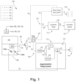
- FIG. 1 an illustrative view of an embodiment of a system in accordance with the disclosure is shown in Fig. 1 and is designated generally by reference character 100.
- FIG. 2 Other embodiments and/or aspects of this disclosure are shown in Fig. 2 .
- a fuel system 100 can include a fuel tank 102, a first fuel line 104, and an in-tank fuel pump 106 disposed in the fuel tank 102 configured to supply fuel from the fuel tank 102 to the first fuel line 104 at a first pressure P0 in an operational state of the in-tank fuel pump 106 (e.g., as shown in Fig. 1 ).
- An in-tank ejector pump 108 can be disposed in the fuel tank 102 configured to supply fuel from the fuel tank 102 to the first fuel line 104 at the first pressure P0 in a failed state of the in-tank fuel pump 106 (e.g., as shown in Fig. 2 ).
- a boost pump 110 can be disposed in the first fuel line 104 configured to receive fuel from the in-tank fuel pump 106 or the in-tank ejector pump 108 and supply the fuel to one or more downstream components 112 at a boost pressure P1.
- the boost pressure P1 can be greater than the first pressure P0.
- the one or more downstream components 112 can be or include any one of, pumps, valves, or fuel consuming components, e.g., as described herein and appreciated by one having ordinary skill in the art in view of this disclosure.
- An augmentation pump system 114 can be disposed in the first fuel line 104 downstream of the boost pump 110 configured to receive fuel from the boost pump 110 and to supply fuel at a second pressure P2 to a fuel consuming component 116 downstream of the augmentation pump system 114 in an operational state of the in-tank fuel pump 106. Or, in the failed state of the in-tank fuel pump 106, the augmentation pump system 114 can be configured to supply fuel at the second pressure P2 to the in-tank ejector pump 108.
- the in-tank ejector pump 108 can include a receiver 108a configured to receive fuel from the augmentation pump system 114 and a venturi section 108b fluidly connected to the receiver 108a configured to draw fuel from the fuel tank 102 through the venturi section 108b (e.g., entrained with the fuel supplied by the augmentation pump system 114 at the receiver 108a) and supply the fuel to the boost pump 110.
- a receiver 108a configured to receive fuel from the augmentation pump system 114 and a venturi section 108b fluidly connected to the receiver 108a configured to draw fuel from the fuel tank 102 through the venturi section 108b (e.g., entrained with the fuel supplied by the augmentation pump system 114 at the receiver 108a) and supply the fuel to the boost pump 110.
- the fuel system 100 can include a second fuel line 118 branching from the first fuel line 104 downstream of the boost pump 110.
- a main pump 120 e.g., an airframe pump
- the fuel consuming component 124 downstream of the main pump 120 can be or include a fuel consuming engine 124 (e.g., including one or more fuel nozzles of the engine).
- an actuation pump 126 can be disposed in a second branch 128 of the second fuel line 118 configured to supply flow from the boost pump 110 to a component 130 downstream of the actuation pump 128 at a fourth pressure P4.
- the downstream component 130 can be or include an actuation system 130.
- a filter 132 can be disposed in the first fuel line 104 at a branch point 134 of the second fuel line 114 from the first fuel line 104.
- a return fuel line 136 can supply excess fuel from the main fuel pump/fuel control system 120 back to the first fuel line 104 downstream of the boost pump 110 and upstream of the filter 132.
- the augmentation pump system 114 can include a centrifugal pump 138 (e.g., a high speed centrifugal pump) disposed in the first fuel line 104 and a selector valve 140 disposed in the first fuel line 104 downstream of the centrifugal pump 138.
- the selector valve 140 can be configured to selectively communicate the centrifugal pump 138 to the component 116 downstream of the augmentation pump system 114 (e.g., as shown in Fig. 1 ) or the in-tank ejector pump 108 (e.g., as shown in Fig. 2 ) based on a state of the selector valve 140.
- the state of the selector valve can be actively controlled, e.g., via a controller 14 [A1] 1.
- the controller 141 can be operatively connected to the selector valve 140 and the controller 141 can be configured to monitor the operational state of the in-tank fuel pump 106 to control the selector valve 140 based on the state of the pump 106.
- the controller 141 can receive an external signal indicative of the state of the in-tank fuel pump 106 (e.g., from another controller)
- the controller 141 can be configured to toggle the selector valve 140 to a first state to communicate the centrifugal pump 138 to the component 116 downstream of the augmentation pump system 114, if the component 116 is needed (e.g., as discussed below).
- the controller 141 can be configured to toggle the selector valve 140 to a second state to communicate the centrifugal pump 138 to the in-tank ejector pump to supply fuel to the boost pump 110 and the rest of the downstream components 112.
- the augmentation pump system 114 can also include an inlet shut off valve 142 disposed in the first fuel line 104 upstream of the centrifugal pump 138.
- the inlet shut off valve 142 can be configured to selectively allow or block flow to the centrifugal pump 138 based on a fuel demand at the fuel consuming component 116 downstream of the augmentation pump system 114 or the status of the in-tank pump 106.
- the component 116 can be an augmenter (e.g., including spray bars of an afterburner system) which may only be needed for a short time during a mission. Thus, if the augmenter 116 is not needed, flow to the centrifugal pump 138 can be blocked by the inlet shut off valve 142, leaving the centrifugal pump 138 running, but running dry.
- the augmentation pump system 114 can include a check valve 144 disposed in the first fuel line 104 between the centrifugal pump 138 and the selector valve 140.
- the check valve 144 can be configured to allow communication of the centrifugal pump 138 with the selector valve 140 based on a pressure in the first fuel line 104 at the outlet of the centrifugal pump 138.
- the augmentation pump system 114 can include a sensor 146 (e.g., a pressure sensor) configured to sense the pressure P2 in the fuel line 104 downstream of the centrifugal pump 138 and output a signal indicative of a state of the centrifugal pump 138 based on the pressure in the fuel line 104.
- the sensor 146 can output a signal indicative of the centrifugal pump 138 actively pumping, or running dry, or in an off state, for example.
- the sensor 146 can be disposed in the fuel line 104 between the check valve 144 and the selector valve 140.
- Conventional fuel systems can include an inducer (e.g., a vacuum pump) in the fuel tank configured to supply fuel to the boost pump in the event of a failed in-tank pump.
- an inducer e.g., a vacuum pump
- the inducer is typically constantly running to pull fuel to the boost pump, which can the overall system less efficient. This can be detrimental to the system when the inducer is only needed for the rare occurrence of an in-tank pump failure.
- Embodiments all for removal of the inducer and replacement with a passive ejector pump, which operates only when needed.
- the ejector pump can be connected to an augmenter pump system, to selective supply flow to the ejector pump only in emergency scenarios, e.g., an in-tank pump failure.
- the augmenter pump system can include a high speed centrifugal pump with dry out functionality, which can operate to supply fuel to an augmenter if needed, or the pump can run idle (e.g., only against the bearings) until it is needed for supplying fuel to the augmenter or the ejector pump based on, the state of the in-tank fuel pump and/or the demand for fuel at the augmenter.
- a high speed centrifugal pump with dry out functionality can operate to supply fuel to an augmenter if needed, or the pump can run idle (e.g., only against the bearings) until it is needed for supplying fuel to the augmenter or the ejector pump based on, the state of the in-tank fuel pump and/or the demand for fuel at the augmenter.
- Removing the inducer and replacing it with an ejector pump, as described herein, can reduce the fuel system weight, parasitic horsepower draws, and pump system heat rejection into the fuel, thus allowing aircraft to carry more fuel and increase aircraft heat rejection into the fuel (from other sources).
- inducers can limit the size and speed of the boost pump, as the boost pump can only run as fast as the inducer. Replacing the inducer with embodiments of the ejector described herein allows for a much faster and smaller boost pump to be utilized, allowing the boost stage to be the high speed element, further improving weight savings and efficiency of the system.
- any numerical values disclosed herein can be exact values or can be values within a range. Further, any terms of approximation (e.g., “about”, “approximately”, “around”) used in this disclosure can mean the stated value within a range. For example, in certain embodiments, the range can be within (plus or minus) 20%, or within 10%, or within 5%, or within 2%, or within any other suitable percentage or number as appreciated by those having ordinary skill in the art (e.g., for known tolerance limits or error ranges).
- a reference to "A and/or B", when used in conjunction with open-ended language such as “comprising” can refer, in one embodiment, to A only (optionally including elements other than B); in another embodiment, to B only (optionally including elements other than A); in yet another embodiment, to both A and B (optionally including other elements); etc.
Landscapes
- Engineering & Computer Science (AREA)
- Chemical & Material Sciences (AREA)
- Combustion & Propulsion (AREA)
- Mechanical Engineering (AREA)
- General Engineering & Computer Science (AREA)
- Cooling, Air Intake And Gas Exhaust, And Fuel Tank Arrangements In Propulsion Units (AREA)
Abstract
A system includes an in-tank fuel pump (106) configured to be disposed in a fuel tank to supply fuel from the fuel tank to a fuel line at a first pressure. A boost pump (110) is configured to be disposed in the fuel line to receive fuel from the in-tank fuel pump (106) and supply the fuel to one or more downstream components at a boost pressure. An augmentation pump system (114) is configured to be disposed in the fuel line to receive fuel from the boost pump (110) and to supply fuel at a second pressure to one of, at least one fuel consuming component downstream of the augmentation pump system (114), or an in-tank ejector pump, based on an operational state of the in-tank fuel pump (106).
Description
- The present disclosure relates to fuel systems and more particularly to fuel systems having ejector pumps.
- Certain conventional fuel systems include an inducer pump in the fuel tank for supplying fuel to the fuel consuming components of a system in the event of a failure of a main fuel tank fuel pump. However, inducer pumps can continuously run during operation of the fuel system, even if the in-tank fuel pump is operational, which can reduce the overall efficiency of the system. Moreover, certain inducers can dictate the speed range and size of the boost pump, because the boost pump can only operate as fast as the inducer.
- The conventional techniques have been considered satisfactory for their intended purpose. However, there is an ever present need for improved systems and methods which are lighter and more efficient. This disclosure provides a solution for this need.
- In accordance with at least one aspect of this disclosure, a system includes an in-tank fuel pump configured to be disposed in a fuel tank to supply fuel from the fuel tank to a fuel line at a first pressure. A boost pump is configured to be disposed in the fuel line to receive fuel from the in-tank fuel pump and supply the fuel to one or more downstream components at a boost pressure. An augmentation pump system is configured to be disposed in the fuel line to receive fuel from the boost pump and to supply fuel at a second pressure to one of, at least one fuel consuming component downstream of the augmentation pump system, or an in-tank ejector pump, based on an operational state of the in-tank fuel pump.
- The system includes the in-tank ejector pump configured to be disposed in the fuel tank to supply fuel from the fuel tank to the boost pump based on an operational state of the in-tank fuel pump (e.g., when the in-tank fuel pump has failed). In embodiments, the in-tank ejector pump can include a receiver configured to receive fuel from the augmentation pump system and a venturi section fluidly connected to the receiver configured to draw fuel from the fuel tank through the venturi section and supply fuel to the boost pump.
- In embodiments, the augmentation pump system can include a centrifugal pump (e.g., a high speed centrifugal pump) configured to be disposed in the fuel line downstream of the boost pump, and a selector valve configured to be disposed in the fuel line downstream of the centrifugal pump. The selector valve can be configured to selectively communicate the centrifugal pump to the at least one fuel consuming component downstream of the augmentation pump system or to the in-tank ejector pump based on a state of the selector valve. In certain embodiments, the state of the selector valve can be actively controlled, e.g., via a controller.
- The controller can be operatively connected to the selector valve and the controller can be configured to monitor the operational state of the in-tank fuel pump. In an operational state of the in-tank fuel pump, the controller can be configured to toggle the selector valve to a first state to communicate the centrifugal pump to the at least one fuel consuming component downstream of the augmentation pump system. In a failed state of the in-tank fuel pump, the controller can be configured to toggle the selector valve to a second state to communicate the centrifugal pump to the in-tank ejector pump.
- In embodiments, the augmentation pump system can include an inlet shut off valve operatively connected to the controller and configured to be disposed in the fuel line upstream of the centrifugal pump. In the operational state of the in-tank fuel pump, the controller can be configured to control the inlet shut off valve to selectively allow or block flow to the centrifugal pump based on a fuel demand fuel consuming component downstream of the centrifugal pump or the operational state of the in-tank fuel pump. In embodiments, the at least one fuel consuming component downstream of the augmentation pump system can be or include an augmenter (e.g., spray bars of an afterburner system).
- In embodiments, the augmentation pump system can include a check valve configured to be disposed in the fuel line between the centrifugal pump and the selector valve. The check valve can be configured to allow communication of the centrifugal pump with the selector valve based on a pressure in the fuel line at the outlet of the centrifugal pump. In certain embodiments, the augmentation pump system can include a sensor (e.g., a pressure sensor) configured to be disposed in the fuel line. The sensor can be configured to sense the pressure in the fuel line downstream of the centrifugal pump and output a signal indicative of a state of the centrifugal pump based on the pressure in the fuel line. In certain embodiments, the sensor can be configured to be disposed in the fuel line between the check valve and the selector valve
- In embodiments, the system can include a main fuel pump (and fuel control therein) configured to be disposed in a first fuel branch of the fuel line, downstream of the boost pump. The main fuel pump can be configured to supply fuel at a third pressure from the boost pump to at least one at least one fuel consuming component downstream of the main pump. In certain embodiments, the at least one fuel consuming component downstream of the main pump can be or include a fuel consuming engine, including one or more fuel nozzles of the engine.
- In embodiments, the system can include an actuation pump configured to be disposed in a second fuel line branch of the fuel line, downstream of the boost pump. The actuation pump can be configured to supply fuel at a fourth pressure from the boost pump to at least one fuel consuming component downstream of the actuation pump. In certain embodiments, the at least one fuel consuming component downstream of the actuation pump can be or include an actuation system. A fuel filter can be configured to be disposed in the fuel line downstream of the boost pump and upstream of the first fuel line branch and the second fuel line branch. In certain embodiments, the fuel filter can be the branch point of the first and second fuel line branches from the fuel line.
- In accordance with at least one aspect of this disclosure, a fuel system can include, a fuel tank, a first fuel line, and an in-tank fuel pump disposed in the fuel tank configured to supply fuel from the fuel tank to the first fuel line at a first pressure in an operational state of the in-tank fuel pump. An in-tank ejector pump can be disposed in the fuel tank configured to supply fuel from the fuel tank to the first fuel line at a first pressure in a failed state of the in-tank fuel pump. A boost pump can be disposed in the first fuel line configured to receive fuel from the in-tank fuel pump or the in-tank ejector pump and supply the fuel to one or more downstream components at a boost pressure. An augmentation pump system can be disposed in the fuel line downstream of the boost pump configured to receive fuel from the boost pump. The augmentation pump system can be configured to supply fuel at a second pressure to one of: at least one fuel consuming component downstream of the augmentation pump system, or, the in-tank ejector pump, based on a state of the in-tank fuel pump (e.g., operational or failed).
- In embodiments the augmentation pump system can include a centrifugal pump disposed in the first fuel line and a selector valve disposed in the first fuel line downstream of the centrifugal pump. The selector valve can be configured to selectively communicate the centrifugal pump to the fuel consuming component downstream of the centrifugal pump or the in-tank ejector pump based on a state of the selector valve. The augmentation pump system can also include an inlet shut off valve disposed in the first fuel line upstream of the centrifugal pump. The inlet shut off valve can be configured to selectively allow or block flow to the centrifugal pump based on a fuel demand at the fuel consuming component downstream of the centrifugal pump or the operational state of the in-tank fuel pump.
- In embodiments the fuel system can include a second fuel line branching from the first fuel line downstream of the boost pump and a main pump disposed in a first branch of the second fuel line configured to supply flow from the boost pump to at least one fuel consuming component downstream of the main pump at a third pressure, where the fuel consuming component can be or include a fuel consuming engine. An actuation pump can be disposed in a second branch of the second fuel line configured to supply flow from the boost pump to at least one fuel consuming component downstream of the actuation pump at a fourth pressure, where the fuel consuming component can be or include an actuation system.
- A filter can be disposed in the first fuel line at a branch point of the second fuel line from the first fuel line. The fuel system can include a return fuel line configured to supply excess fuel from the main fuel pump back to the first fuel line downstream of the boost pump and upstream of the filter.
- These and other features of the systems and methods of the subject disclosure will become more readily apparent to those skilled in the art from the following detailed description taken in conjunction with the drawings.
- So that those skilled in the art to which the subject disclosure appertains will readily understand how to make and use the devices and methods of the subject disclosure without undue experimentation, other embodiments thereof will be described in detail herein below with reference to certain figures, wherein:
-
Fig. 1 is a schematic diagram of an embodiment of a system in accordance with this disclosure, showing the system in a first state; and -
Fig. 2 is a schematic diagram of the system ofFig. 1 , showing the system in a second state. - Reference will now be made to the drawings wherein like reference numerals identify similar structural features or aspects of the subject disclosure. For purposes of explanation and illustration, and not limitation, an illustrative view of an embodiment of a system in accordance with the disclosure is shown in
Fig. 1 and is designated generally byreference character 100. Other embodiments and/or aspects of this disclosure are shown inFig. 2 . - In accordance with at least one aspect of this disclosure, a
fuel system 100 can include afuel tank 102, afirst fuel line 104, and an in-tank fuel pump 106 disposed in thefuel tank 102 configured to supply fuel from thefuel tank 102 to thefirst fuel line 104 at a first pressure P0 in an operational state of the in-tank fuel pump 106 (e.g., as shown inFig. 1 ). An in-tank ejector pump 108 can be disposed in thefuel tank 102 configured to supply fuel from thefuel tank 102 to thefirst fuel line 104 at the first pressure P0 in a failed state of the in-tank fuel pump 106 (e.g., as shown inFig. 2 ). Aboost pump 110 can be disposed in thefirst fuel line 104 configured to receive fuel from the in-tank fuel pump 106 or the in-tank ejector pump 108 and supply the fuel to one or moredownstream components 112 at a boost pressure P1. The boost pressure P1 can be greater than the first pressure P0. The one or moredownstream components 112 can be or include any one of, pumps, valves, or fuel consuming components, e.g., as described herein and appreciated by one having ordinary skill in the art in view of this disclosure. - An
augmentation pump system 114 can be disposed in thefirst fuel line 104 downstream of theboost pump 110 configured to receive fuel from theboost pump 110 and to supply fuel at a second pressure P2 to afuel consuming component 116 downstream of theaugmentation pump system 114 in an operational state of the in-tank fuel pump 106. Or, in the failed state of the in-tank fuel pump 106, theaugmentation pump system 114 can be configured to supply fuel at the second pressure P2 to the in-tank ejector pump 108. In embodiments, the in-tank ejector pump 108 can include areceiver 108a configured to receive fuel from theaugmentation pump system 114 and aventuri section 108b fluidly connected to thereceiver 108a configured to draw fuel from thefuel tank 102 through theventuri section 108b (e.g., entrained with the fuel supplied by theaugmentation pump system 114 at thereceiver 108a) and supply the fuel to theboost pump 110. - In embodiments the
fuel system 100 can include asecond fuel line 118 branching from thefirst fuel line 104 downstream of theboost pump 110. A main pump 120 (e.g., an airframe pump) can be disposed in afirst branch 122 of thesecond fuel line 118 configured to supply flow from theboost pump 110 to afuel consuming component 124 downstream of themain pump 120 at a third pressure P3. In embodiments, thefuel consuming component 124 downstream of themain pump 120 can be or include a fuel consuming engine 124 (e.g., including one or more fuel nozzles of the engine). In embodiments, e.g., as shown, anactuation pump 126 can be disposed in asecond branch 128 of thesecond fuel line 118 configured to supply flow from theboost pump 110 to acomponent 130 downstream of theactuation pump 128 at a fourth pressure P4. In embodiments, thedownstream component 130 can be or include anactuation system 130. - A
filter 132 can be disposed in thefirst fuel line 104 at abranch point 134 of thesecond fuel line 114 from thefirst fuel line 104. Areturn fuel line 136 can supply excess fuel from the main fuel pump/fuel control system 120 back to thefirst fuel line 104 downstream of theboost pump 110 and upstream of thefilter 132. - Still with reference to
Figs. 1 and2 , in embodiments theaugmentation pump system 114 can include a centrifugal pump 138 (e.g., a high speed centrifugal pump) disposed in thefirst fuel line 104 and aselector valve 140 disposed in thefirst fuel line 104 downstream of thecentrifugal pump 138. Theselector valve 140 can be configured to selectively communicate thecentrifugal pump 138 to thecomponent 116 downstream of the augmentation pump system 114 (e.g., as shown inFig. 1 ) or the in-tank ejector pump 108 (e.g., as shown inFig. 2 ) based on a state of theselector valve 140. In certain embodiments, the state of the selector valve can be actively controlled, e.g., via a controller 14[A1]1. - The
controller 141 can be operatively connected to theselector valve 140 and thecontroller 141 can be configured to monitor the operational state of the in-tank fuel pump 106 to control theselector valve 140 based on the state of thepump 106. In certain embodiments, thecontroller 141 can receive an external signal indicative of the state of the in-tank fuel pump 106 (e.g., from another controller) In the operational state of the in-tank fuel pump (Fig. 1 ), thecontroller 141 can be configured to toggle theselector valve 140 to a first state to communicate thecentrifugal pump 138 to thecomponent 116 downstream of theaugmentation pump system 114, if thecomponent 116 is needed (e.g., as discussed below). In the failed state of the in-tank fuel pump 106 (Fig. 2 ), thecontroller 141 can be configured to toggle theselector valve 140 to a second state to communicate thecentrifugal pump 138 to the in-tank ejector pump to supply fuel to theboost pump 110 and the rest of thedownstream components 112. - The
augmentation pump system 114 can also include an inlet shut offvalve 142 disposed in thefirst fuel line 104 upstream of thecentrifugal pump 138. The inlet shut offvalve 142 can be configured to selectively allow or block flow to thecentrifugal pump 138 based on a fuel demand at thefuel consuming component 116 downstream of theaugmentation pump system 114 or the status of the in-tank pump 106. In embodiments, thecomponent 116 can be an augmenter (e.g., including spray bars of an afterburner system) which may only be needed for a short time during a mission. Thus, if theaugmenter 116 is not needed, flow to thecentrifugal pump 138 can be blocked by the inlet shut offvalve 142, leaving thecentrifugal pump 138 running, but running dry. - In embodiments, the
augmentation pump system 114 can include acheck valve 144 disposed in thefirst fuel line 104 between thecentrifugal pump 138 and theselector valve 140. Thecheck valve 144 can be configured to allow communication of thecentrifugal pump 138 with theselector valve 140 based on a pressure in thefirst fuel line 104 at the outlet of thecentrifugal pump 138. In certain embodiments, theaugmentation pump system 114 can include a sensor 146 (e.g., a pressure sensor) configured to sense the pressure P2 in thefuel line 104 downstream of thecentrifugal pump 138 and output a signal indicative of a state of thecentrifugal pump 138 based on the pressure in thefuel line 104. Thesensor 146 can output a signal indicative of thecentrifugal pump 138 actively pumping, or running dry, or in an off state, for example. In certain embodiments, thesensor 146 can be disposed in thefuel line 104 between thecheck valve 144 and theselector valve 140. - Conventional fuel systems can include an inducer (e.g., a vacuum pump) in the fuel tank configured to supply fuel to the boost pump in the event of a failed in-tank pump. However, in order to be ready to supply fuel in the event of a failure, the inducer is typically constantly running to pull fuel to the boost pump, which can the overall system less efficient. This can be detrimental to the system when the inducer is only needed for the rare occurrence of an in-tank pump failure. Embodiments all for removal of the inducer and replacement with a passive ejector pump, which operates only when needed. The ejector pump can be connected to an augmenter pump system, to selective supply flow to the ejector pump only in emergency scenarios, e.g., an in-tank pump failure. The augmenter pump system can include a high speed centrifugal pump with dry out functionality, which can operate to supply fuel to an augmenter if needed, or the pump can run idle (e.g., only against the bearings) until it is needed for supplying fuel to the augmenter or the ejector pump based on, the state of the in-tank fuel pump and/or the demand for fuel at the augmenter.
- Removing the inducer and replacing it with an ejector pump, as described herein, can reduce the fuel system weight, parasitic horsepower draws, and pump system heat rejection into the fuel, thus allowing aircraft to carry more fuel and increase aircraft heat rejection into the fuel (from other sources). Further, inducers can limit the size and speed of the boost pump, as the boost pump can only run as fast as the inducer. Replacing the inducer with embodiments of the ejector described herein allows for a much faster and smaller boost pump to be utilized, allowing the boost stage to be the high speed element, further improving weight savings and efficiency of the system.
- Those having ordinary skill in the art understand that any numerical values disclosed herein can be exact values or can be values within a range. Further, any terms of approximation (e.g., "about", "approximately", "around") used in this disclosure can mean the stated value within a range. For example, in certain embodiments, the range can be within (plus or minus) 20%, or within 10%, or within 5%, or within 2%, or within any other suitable percentage or number as appreciated by those having ordinary skill in the art (e.g., for known tolerance limits or error ranges).
- The articles "a", "an", and "the" as used herein and in the appended claims are used herein to refer to one or to more than one (i.e., to at least one) of the grammatical object of the article unless the context clearly indicates otherwise. By way of example, "an element" means one element or more than one element.
- The phrase "and/or," as used herein in the specification and in the claims, should be understood to mean "either or both" of the elements so conjoined, i.e., elements that are conjunctively present in some cases and disjunctively present in other cases. Multiple elements listed with "and/or" should be construed in the same fashion, i.e., "one or more" of the elements so conjoined. Other elements may optionally be present other than the elements specifically identified by the "and/or" clause, whether related or unrelated to those elements specifically identified. Thus, as a non-limiting example, a reference to "A and/or B", when used in conjunction with open-ended language such as "comprising" can refer, in one embodiment, to A only (optionally including elements other than B); in another embodiment, to B only (optionally including elements other than A); in yet another embodiment, to both A and B (optionally including other elements); etc.
- As used herein in the specification and in the claims, "or" should be understood to have the same meaning as "and/or" as defined above. For example, when separating items in a list, "or" or "and/or" shall be interpreted as being inclusive, i.e., the inclusion of at least one, but also including more than one, of a number or list of elements, and, optionally, additional unlisted items. Only terms clearly indicated to the contrary, such as "only one of' or "exactly one of," or, when used in the claims, "consisting of," will refer to the inclusion of exactly one element of a number or list of elements. In general, the term "or" as used herein shall only be interpreted as indicating exclusive alternatives (i.e., "one or the other but not both") when preceded by terms of exclusivity, such as "either," "one of," "only one of," or "exactly one of."
- Any suitable combination(s) of any disclosed embodiments and/or any suitable portion(s) thereof are contemplated herein as appreciated by those having ordinary skill in the art in view of this disclosure.
- The embodiments of the present disclosure, as described above and shown in the drawings, provide for improvement in the art to which they pertain. While the apparatus and methods of the subject disclosure have been shown and described, those skilled in the art will readily appreciate that changes and/or modifications may be made thereto without departing from the scope of the subject disclosure.
Claims (15)
- A system, comprising:an in-tank fuel pump (106) configured to be disposed in a fuel tank to supply fuel from the fuel tank to a fuel line at a first pressure;a boost pump (110) configured to be disposed in the fuel line to receive fuel from the in-tank fuel pump (106) and supply the fuel to one or more downstream components at a boost pressure;an augmentation pump system (114) configured to be disposed in the fuel line to receive fuel from the boost pump (110) and to supply fuel at a second pressure to one of: a fuel consuming component downstream of the augmentation pump system (114), or an in-tank ejector pump, based on an operational state of the in-tank fuel pump (106).
- The system of claim 1, further comprising the in-tank ejector pump, wherein the in-tank ejector pump is configured to be disposed in the fuel tank to supply fuel from the fuel tank to the boost pump (110) based on an operational state of the in-tank fuel pump (106).
- The system of claim 2, wherein the in-tank ejector pump includes a receiver configured to receive fuel from the augmentation pump system (114) and a venturi section fluidly connected to the receiver configured to draw fuel from the fuel tank through the venturi section and supply fuel to the boost pump (110).
- The system of claim 2, wherein the augmentation pump system (114) comprises a centrifugal pump configured to be disposed in the fuel line downstream of the boost pump (110), and a selector valve configured to be disposed in the fuel line downstream of the centrifugal pump, wherein the selector valve is configured to selectively communicate the centrifugal pump to the at least one downstream fuel consuming component or to the in-tank ejector pump based on a state of the selector valve.
- The system of claim 4, further comprising a controller operatively connected to the selector valve, wherein the controller is configured to monitor the operational state of the in-tank fuel pump (106),wherein in an operational state of the in-tank fuel pump (106), the controller is configured to toggle the selector valve to a first state to communicate the centrifugal pump to the fuel consuming component downstream of the augmentation pump system (114), andwherein in a failed state of the in-tank fuel pump (106), the controller is configured to toggle the selector valve to a second state to communicate the centrifugal pump to the in-tank ejector pump.
- The system of claim 5, wherein the augmentation pump system (114) further comprises an inlet shut off valve operatively connected to the controller and configured to be disposed in the fuel line upstream of the centrifugal pump, wherein in the operational state of the in-tank fuel pump (106), the controller is configured to control the inlet shut off valve to selectively allow or block flow to the centrifugal pump based on a fuel demand of the fuel consuming component downstream of the augmentation pump system (114) or the operational state of the in-tank fuel pump (106).
- The system of claim 6, wherein the fuel consuming component downstream of the augmentation pump system (114) includes an augmenter, or wherein the augmentation pump system (114) further comprises a check valve configured to be disposed in the fuel line between the centrifugal pump and the selector valve configured to allow communication of the centrifugal pump with the selector valve based on a pressure in the fuel line at the outlet of the centrifugal pump.
- The system of any preceding claim, further comprising, a main fuel pump configured to be disposed in a first fuel branch, downstream of the boost pump (110), wherein the main fuel pump is configured to supply fuel at a third pressure from the boost pump (110) to a fuel consuming component downstream of the main pump.
- The system of claim 8, wherein the fuel consuming component downstream of the main pump includes a fuel consuming engine, or . further comprising, an actuation pump configured to be disposed in a second fuel line branch, downstream of the boost pump (110), wherein the actuation pump is configured to supply fuel at a fourth pressure from the boost pump (110) to a fuel consuming component downstream of the actuation pump.
- The system of claim 9, wherein the fuel consuming component downstream of the actuation pump includes an actuation system, and optionally further comprising a filter configured to be disposed in the fuel line downstream of the boost pump (110) and upstream of the first fuel line branch and the second fuel line branch.
- A fuel system, comprising:a fuel tank;a first fuel line;an in-tank fuel pump disposed in the fuel tank configured to supply fuel from the fuel tank to the first fuel line at a first pressure in an operational state of the in-tank fuel pump (106);an in-tank ejector pump disposed in the fuel tank configured to supply fuel from the fuel tank to the first fuel line at a first pressure in a failed state of the in-tank fuel pump (106);a boost pump (110) disposed in the first fuel line configured to receive fuel from the in-tank fuel pump (106) or the in-tank ejector pump and supply the fuel to one or more downstream components at a boost pressure;an augmentation pump system (114) disposed in the fuel line downstream of the boost pump (110) configured to receive fuel from the boost pump (110) and to supply fuel at a second pressure to one of: at least one component downstream of the augmentation pump system (114), or, the in-tank ejector pump, based on a state of the in-tank fuel pump (106).
- The fuel system of claim 11, wherein the augmentation pump system (114) further comprises a centrifugal pump disposed in the first fuel line and a selector valve disposed in the first fuel line downstream of the centrifugal pump, wherein the selector valve is configured to selectively communicate the centrifugal pump to the fuel consuming component downstream of the centrifugal pump or the in-tank ejector pump based on a state of the selector valve, and optionally wherein the augmentation pump system (114) further includes an inlet shut off valve disposed in the first fuel line upstream of the centrifugal pump, wherein the inlet shut off valve is configured to selectively allow or block flow to the centrifugal pump based on a fuel demand at the fuel consuming component downstream of the centrifugal pump or the operational state of the in-tank fuel pump (106).
- The fuel system of claim 11, further comprising;a second fuel line branching from the first fuel line downstream of the boost pump (110); anda main pump disposed in a first branch of the second fuel line configured to supply flow from the boost pump (110) to fuel consuming component downstream of the main pump at a third pressure, wherein the fuel consuming component downstream of the main pump includes a fuel consuming engine.
- The fuel system of claim 13, further comprising;
an actuation pump disposed in a second branch of the second fuel line configured to supply flow from the boost pump (110) to a fuel consuming component downstream of the actuation pump at a fourth pressure, wherein the fuel consuming component downstream of the actuation pump includes an actuation system, and optionally further comprising a filter disposed in the first fuel line at a branch point of the second fuel line from the first fuel line. - The fuel system of any preceding claim, further comprising a return fuel line configured to supply excess fuel from the main fuel pump back to the first fuel line downstream of the boost pump (110) and upstream of the filter.
Applications Claiming Priority (1)
| Application Number | Priority Date | Filing Date | Title |
|---|---|---|---|
| US18/208,693 US12025084B1 (en) | 2023-06-12 | 2023-06-12 | In-tank ejector pump |
Publications (1)
| Publication Number | Publication Date |
|---|---|
| EP4477862A1 true EP4477862A1 (en) | 2024-12-18 |
Family
ID=91465104
Family Applications (1)
| Application Number | Title | Priority Date | Filing Date |
|---|---|---|---|
| EP24180877.3A Pending EP4477862A1 (en) | 2023-06-12 | 2024-06-07 | In-tank ejector pump |
Country Status (2)
| Country | Link |
|---|---|
| US (1) | US12025084B1 (en) |
| EP (1) | EP4477862A1 (en) |
Families Citing this family (1)
| Publication number | Priority date | Publication date | Assignee | Title |
|---|---|---|---|---|
| US12460819B2 (en) * | 2024-03-07 | 2025-11-04 | Rtx Corporation | Continuous flow fuel system |
Citations (4)
| Publication number | Priority date | Publication date | Assignee | Title |
|---|---|---|---|---|
| US2812715A (en) * | 1954-06-23 | 1957-11-12 | Westinghouse Electric Corp | Fuel system |
| US3275061A (en) * | 1964-01-02 | 1966-09-27 | Boeing Co | Fuel feeding systems |
| EP0886054B1 (en) * | 1997-06-16 | 2004-01-28 | United Technologies Corporation | Combined pressure regulating and motive flow valve |
| EP3712407A1 (en) * | 2019-03-20 | 2020-09-23 | United Technologies Corporation | Secondary fuel flow demand fuel pumping system |
Family Cites Families (14)
| Publication number | Priority date | Publication date | Assignee | Title |
|---|---|---|---|---|
| US4339917A (en) | 1979-06-13 | 1982-07-20 | The Garrett Corporation | Fuel delivery system and method |
| US4332527A (en) | 1979-08-10 | 1982-06-01 | Lear Siegler, Inc. | Variable speed centrifugal pump |
| US4704070A (en) | 1983-04-25 | 1987-11-03 | Iseman Walter J | Fuel system bubble dissipation device |
| US5647328A (en) * | 1995-06-30 | 1997-07-15 | Walbro Corporation | In-tank fuel pump and reservoir |
| DE10327320A1 (en) * | 2003-06-16 | 2005-01-27 | Siemens Ag | Fuel supply system |
| US20070283935A1 (en) * | 2006-05-16 | 2007-12-13 | Toyota Jidosha Kabushiki Kaisha | Fuel pump control apparatus for internal combustion engine |
| JP5126339B2 (en) * | 2010-02-25 | 2013-01-23 | 株式会社デンソー | Fuel supply device |
| FR2959529B1 (en) | 2010-04-28 | 2014-04-18 | Snecma | TURBOMACHINE FUEL SYSTEM WITH A JET PUMP FOR A BP PUMP |
| US20140219826A1 (en) | 2011-08-15 | 2014-08-07 | Eaton Corporation | Fuel system using dual pressure hi-speed centrifugal pump arrangement |
| SE537004C2 (en) * | 2013-03-22 | 2014-12-02 | Scania Cv Ab | Combustion engine fuel system and method for handling water contained in fuel in a fuel system |
| JP6131785B2 (en) | 2013-08-30 | 2017-05-24 | 株式会社Ihi | Aircraft engine fuel supply system |
| US9435286B2 (en) * | 2014-02-03 | 2016-09-06 | Denso International America, Inc. | Method to reduce fuel system power consumption |
| US20180050812A1 (en) * | 2016-08-16 | 2018-02-22 | Hamilton Sundstrand Corporation | Aircraft fuel pump systems |
| WO2020131835A1 (en) * | 2018-12-20 | 2020-06-25 | Walbro Llc | Multiple pump fuel system |
-
2023
- 2023-06-12 US US18/208,693 patent/US12025084B1/en active Active
-
2024
- 2024-06-07 EP EP24180877.3A patent/EP4477862A1/en active Pending
Patent Citations (4)
| Publication number | Priority date | Publication date | Assignee | Title |
|---|---|---|---|---|
| US2812715A (en) * | 1954-06-23 | 1957-11-12 | Westinghouse Electric Corp | Fuel system |
| US3275061A (en) * | 1964-01-02 | 1966-09-27 | Boeing Co | Fuel feeding systems |
| EP0886054B1 (en) * | 1997-06-16 | 2004-01-28 | United Technologies Corporation | Combined pressure regulating and motive flow valve |
| EP3712407A1 (en) * | 2019-03-20 | 2020-09-23 | United Technologies Corporation | Secondary fuel flow demand fuel pumping system |
Also Published As
| Publication number | Publication date |
|---|---|
| US12025084B1 (en) | 2024-07-02 |
Similar Documents
| Publication | Publication Date | Title |
|---|---|---|
| US7118336B2 (en) | Pressurized oil supply for propeller engine system | |
| US12372050B2 (en) | Removing non-homogeneous ice from a fuel system | |
| CA2639025C (en) | Gas turbine oil scavenging system | |
| EP3232036B1 (en) | Dual pump fuel system with pump sharing connection | |
| US11203978B2 (en) | Dual pump unit with boost pump | |
| EP2615260B1 (en) | Gas turbine engine bearing chamber seals | |
| CA2953533C (en) | Jet engine cold air cooling system | |
| EP4477862A1 (en) | In-tank ejector pump | |
| CN104884765B (en) | Apparatus and method for temporarily increasing power | |
| US20090211558A1 (en) | Hybrid electrical/mechanical turbine engine fuel supply system | |
| EP3670850A1 (en) | Two tier lubrication system | |
| US12071898B2 (en) | Fluid pump systems | |
| EP2796688A2 (en) | System for controlling two positive displacement pumps | |
| US9732678B2 (en) | Speed card-controlled override fuel pump assist | |
| EP3473835B1 (en) | Two stage oxygen removal for gas turbine engine fuel system | |
| CN114517739A (en) | Air management system | |
| US12031487B1 (en) | Fuel system having variable displacement pump failure modes | |
| EP4191039B1 (en) | Fuel pump systems | |
| EP4151845B1 (en) | Fuel system with ecology function | |
| US20230167773A1 (en) | Fuel delivery pump selection | |
| CN112173124B (en) | Air management system for an aircraft, method for supplying pressurized air and aircraft | |
| SE542071C2 (en) | Fuel system for an internal combustion engine and method of operating fuel system | |
| EP4497921A1 (en) | Hydraulic motoring of engine |
Legal Events
| Date | Code | Title | Description |
|---|---|---|---|
| PUAI | Public reference made under article 153(3) epc to a published international application that has entered the european phase |
Free format text: ORIGINAL CODE: 0009012 |
|
| STAA | Information on the status of an ep patent application or granted ep patent |
Free format text: STATUS: THE APPLICATION HAS BEEN PUBLISHED |
|
| AK | Designated contracting states |
Kind code of ref document: A1 Designated state(s): AL AT BE BG CH CY CZ DE DK EE ES FI FR GB GR HR HU IE IS IT LI LT LU LV MC ME MK MT NL NO PL PT RO RS SE SI SK SM TR |
|
| STAA | Information on the status of an ep patent application or granted ep patent |
Free format text: STATUS: REQUEST FOR EXAMINATION WAS MADE |
|
| 17P | Request for examination filed |
Effective date: 20250617 |