EP4477856A2 - Gas turbine engine with water recovery system - Google Patents
Gas turbine engine with water recovery system Download PDFInfo
- Publication number
- EP4477856A2 EP4477856A2 EP24182412.7A EP24182412A EP4477856A2 EP 4477856 A2 EP4477856 A2 EP 4477856A2 EP 24182412 A EP24182412 A EP 24182412A EP 4477856 A2 EP4477856 A2 EP 4477856A2
- Authority
- EP
- European Patent Office
- Prior art keywords
- fuel
- flowpath
- section
- rotor
- turboexpander
- Prior art date
- Legal status (The legal status is an assumption and is not a legal conclusion. Google has not performed a legal analysis and makes no representation as to the accuracy of the status listed.)
- Pending
Links
Images




Classifications
-
- F—MECHANICAL ENGINEERING; LIGHTING; HEATING; WEAPONS; BLASTING
- F02—COMBUSTION ENGINES; HOT-GAS OR COMBUSTION-PRODUCT ENGINE PLANTS
- F02C—GAS-TURBINE PLANTS; AIR INTAKES FOR JET-PROPULSION PLANTS; CONTROLLING FUEL SUPPLY IN AIR-BREATHING JET-PROPULSION PLANTS
- F02C3/00—Gas-turbine plants characterised by the use of combustion products as the working fluid
- F02C3/20—Gas-turbine plants characterised by the use of combustion products as the working fluid using a special fuel, oxidant, or dilution fluid to generate the combustion products
- F02C3/30—Adding water, steam or other fluids for influencing combustion, e.g. to obtain cleaner exhaust gases
-
- F—MECHANICAL ENGINEERING; LIGHTING; HEATING; WEAPONS; BLASTING
- F02—COMBUSTION ENGINES; HOT-GAS OR COMBUSTION-PRODUCT ENGINE PLANTS
- F02C—GAS-TURBINE PLANTS; AIR INTAKES FOR JET-PROPULSION PLANTS; CONTROLLING FUEL SUPPLY IN AIR-BREATHING JET-PROPULSION PLANTS
- F02C3/00—Gas-turbine plants characterised by the use of combustion products as the working fluid
- F02C3/20—Gas-turbine plants characterised by the use of combustion products as the working fluid using a special fuel, oxidant, or dilution fluid to generate the combustion products
- F02C3/22—Gas-turbine plants characterised by the use of combustion products as the working fluid using a special fuel, oxidant, or dilution fluid to generate the combustion products the fuel or oxidant being gaseous at standard temperature and pressure
-
- F—MECHANICAL ENGINEERING; LIGHTING; HEATING; WEAPONS; BLASTING
- F02—COMBUSTION ENGINES; HOT-GAS OR COMBUSTION-PRODUCT ENGINE PLANTS
- F02C—GAS-TURBINE PLANTS; AIR INTAKES FOR JET-PROPULSION PLANTS; CONTROLLING FUEL SUPPLY IN AIR-BREATHING JET-PROPULSION PLANTS
- F02C6/00—Plural gas-turbine plants; Combinations of gas-turbine plants with other apparatus; Adaptations of gas-turbine plants for special use
- F02C6/20—Adaptations of gas-turbine plants for driving vehicles
- F02C6/206—Adaptations of gas-turbine plants for driving vehicles the vehicles being airscrew driven
-
- F—MECHANICAL ENGINEERING; LIGHTING; HEATING; WEAPONS; BLASTING
- F02—COMBUSTION ENGINES; HOT-GAS OR COMBUSTION-PRODUCT ENGINE PLANTS
- F02C—GAS-TURBINE PLANTS; AIR INTAKES FOR JET-PROPULSION PLANTS; CONTROLLING FUEL SUPPLY IN AIR-BREATHING JET-PROPULSION PLANTS
- F02C7/00—Features, components parts, details or accessories, not provided for in, or of interest apart form groups F02C1/00 - F02C6/00; Air intakes for jet-propulsion plants
- F02C7/12—Cooling of plants
- F02C7/14—Cooling of plants of fluids in the plant, e.g. lubricant or fuel
- F02C7/141—Cooling of plants of fluids in the plant, e.g. lubricant or fuel of working fluid
- F02C7/143—Cooling of plants of fluids in the plant, e.g. lubricant or fuel of working fluid before or between the compressor stages
- F02C7/1435—Cooling of plants of fluids in the plant, e.g. lubricant or fuel of working fluid before or between the compressor stages by water injection
-
- F—MECHANICAL ENGINEERING; LIGHTING; HEATING; WEAPONS; BLASTING
- F02—COMBUSTION ENGINES; HOT-GAS OR COMBUSTION-PRODUCT ENGINE PLANTS
- F02C—GAS-TURBINE PLANTS; AIR INTAKES FOR JET-PROPULSION PLANTS; CONTROLLING FUEL SUPPLY IN AIR-BREATHING JET-PROPULSION PLANTS
- F02C7/00—Features, components parts, details or accessories, not provided for in, or of interest apart form groups F02C1/00 - F02C6/00; Air intakes for jet-propulsion plants
- F02C7/12—Cooling of plants
- F02C7/16—Cooling of plants characterised by cooling medium
- F02C7/18—Cooling of plants characterised by cooling medium the medium being gaseous, e.g. air
-
- F—MECHANICAL ENGINEERING; LIGHTING; HEATING; WEAPONS; BLASTING
- F02—COMBUSTION ENGINES; HOT-GAS OR COMBUSTION-PRODUCT ENGINE PLANTS
- F02C—GAS-TURBINE PLANTS; AIR INTAKES FOR JET-PROPULSION PLANTS; CONTROLLING FUEL SUPPLY IN AIR-BREATHING JET-PROPULSION PLANTS
- F02C7/00—Features, components parts, details or accessories, not provided for in, or of interest apart form groups F02C1/00 - F02C6/00; Air intakes for jet-propulsion plants
- F02C7/22—Fuel supply systems
-
- F—MECHANICAL ENGINEERING; LIGHTING; HEATING; WEAPONS; BLASTING
- F02—COMBUSTION ENGINES; HOT-GAS OR COMBUSTION-PRODUCT ENGINE PLANTS
- F02C—GAS-TURBINE PLANTS; AIR INTAKES FOR JET-PROPULSION PLANTS; CONTROLLING FUEL SUPPLY IN AIR-BREATHING JET-PROPULSION PLANTS
- F02C7/00—Features, components parts, details or accessories, not provided for in, or of interest apart form groups F02C1/00 - F02C6/00; Air intakes for jet-propulsion plants
- F02C7/22—Fuel supply systems
- F02C7/224—Heating fuel before feeding to the burner
-
- F—MECHANICAL ENGINEERING; LIGHTING; HEATING; WEAPONS; BLASTING
- F05—INDEXING SCHEMES RELATING TO ENGINES OR PUMPS IN VARIOUS SUBCLASSES OF CLASSES F01-F04
- F05D—INDEXING SCHEME FOR ASPECTS RELATING TO NON-POSITIVE-DISPLACEMENT MACHINES OR ENGINES, GAS-TURBINES OR JET-PROPULSION PLANTS
- F05D2220/00—Application
- F05D2220/60—Application making use of surplus or waste energy
- F05D2220/62—Application making use of surplus or waste energy with energy recovery turbines
-
- F—MECHANICAL ENGINEERING; LIGHTING; HEATING; WEAPONS; BLASTING
- F05—INDEXING SCHEMES RELATING TO ENGINES OR PUMPS IN VARIOUS SUBCLASSES OF CLASSES F01-F04
- F05D—INDEXING SCHEME FOR ASPECTS RELATING TO NON-POSITIVE-DISPLACEMENT MACHINES OR ENGINES, GAS-TURBINES OR JET-PROPULSION PLANTS
- F05D2260/00—Function
- F05D2260/20—Heat transfer, e.g. cooling
- F05D2260/213—Heat transfer, e.g. cooling by the provision of a heat exchanger within the cooling circuit
-
- F—MECHANICAL ENGINEERING; LIGHTING; HEATING; WEAPONS; BLASTING
- F05—INDEXING SCHEMES RELATING TO ENGINES OR PUMPS IN VARIOUS SUBCLASSES OF CLASSES F01-F04
- F05D—INDEXING SCHEME FOR ASPECTS RELATING TO NON-POSITIVE-DISPLACEMENT MACHINES OR ENGINES, GAS-TURBINES OR JET-PROPULSION PLANTS
- F05D2260/00—Function
- F05D2260/20—Heat transfer, e.g. cooling
- F05D2260/232—Heat transfer, e.g. cooling characterized by the cooling medium
- F05D2260/2322—Heat transfer, e.g. cooling characterized by the cooling medium steam
-
- F—MECHANICAL ENGINEERING; LIGHTING; HEATING; WEAPONS; BLASTING
- F05—INDEXING SCHEMES RELATING TO ENGINES OR PUMPS IN VARIOUS SUBCLASSES OF CLASSES F01-F04
- F05D—INDEXING SCHEME FOR ASPECTS RELATING TO NON-POSITIVE-DISPLACEMENT MACHINES OR ENGINES, GAS-TURBINES OR JET-PROPULSION PLANTS
- F05D2260/00—Function
- F05D2260/60—Fluid transfer
- F05D2260/606—Bypassing the fluid
-
- F—MECHANICAL ENGINEERING; LIGHTING; HEATING; WEAPONS; BLASTING
- F05—INDEXING SCHEMES RELATING TO ENGINES OR PUMPS IN VARIOUS SUBCLASSES OF CLASSES F01-F04
- F05D—INDEXING SCHEME FOR ASPECTS RELATING TO NON-POSITIVE-DISPLACEMENT MACHINES OR ENGINES, GAS-TURBINES OR JET-PROPULSION PLANTS
- F05D2260/00—Function
- F05D2260/60—Fluid transfer
- F05D2260/609—Deoiling or demisting
Definitions
- This disclosure relates generally to an aircraft and, more particularly, to a turbine engine system for the aircraft.
- an engine system includes an open propulsor rotor, an engine core assembly, a bypass flowpath and a condenser.
- the engine core assembly is configured to drive rotation of the open propulsor rotor.
- the engine core assembly includes a core flowpath, a compressor section, a combustor section and a turbine section.
- the core flowpath extends through the compressor section, the combustor section and the turbine section from an inlet into the core flowpath to an exhaust from the core flowpath.
- the bypass flowpath bypasses the engine core assembly.
- the condenser is configured to exchange heat energy between combustion products flowing within the core flowpath downstream of the combustor section and bypass air flowing within the bypass flowpath.
- another engine system includes an engine core assembly, a recovery system and a fuel system.
- the engine core assembly includes a core flowpath, a compressor section, a combustor section and a turbine section.
- the core flowpath extends through the compressor section, the combustor section and the turbine section from an inlet into the core flowpath to an exhaust from the core flowpath.
- the combustor section includes a combustor.
- the recovery system includes an evaporator and a recovery system turboexpander section. The evaporator is configured to exchange heat energy between combustion products flowing within the core flowpath downstream of the combustor section and water flowing within the recovery system to evaporate the water into steam.
- the recovery system turboexpander section includes a recovery system turboexpander rotor.
- the recovery system is configured to expand at least some of the steam across the recovery system turboexpander section to drive rotation of the recovery system turboexpander rotor.
- the fuel system includes a fuel flowpath, a fuel injector and a fuel system turboexpander section.
- the fuel flowpath is configured to direct fuel through the fuel system turboexpander section to the fuel injector.
- the fuel injector is configured to introduce the fuel into the combustor.
- the fuel system turboexpander section includes a fuel system turboexpander rotor.
- the fuel system is configured to expand the fuel flowing within the fuel flowpath across the fuel system turboexpander section to drive rotation of the fuel system turboexpander rotor.
- another engine system includes an un-ducted propulsor rotor, an engine core assembly, a fuel system, an internal second flowpath and a heat exchanger.
- the engine core assembly is configured to drive rotation of the un-ducted propulsor rotor.
- the engine core assembly includes a core flowpath, a compressor section, a combustor section and a turbine section.
- the core flowpath extends through the compressor section, the combustor section and the turbine section from an inlet into the core flowpath to an exhaust from the core flowpath.
- the combustor section includes a combustor.
- the fuel system includes a fuel flowpath and a fuel injector.
- the fuel flowpath is configured to direct hydrogen fuel to the fuel injector.
- the fuel injector is configured to introduce the hydrogen fuel into the combustor.
- the internal second flowpath extends around the engine core assembly.
- the heat exchanger is configured to exchange heat energy between a working fluid and air flowing within the internal second flowpath.
- the working fluid may be combustion products flowing within the core flowpath downstream of the turbine section.
- the engine system may also include an un-ducted propulsor rotor. At least one of the engine core assembly, the recovery system turboexpander rotor or the fuel system turboexpander rotor may be configured to drive rotation of the un-ducted propulsor rotor.
- the engine system may also include a water separator.
- the condenser may be configured to condense water vapor flowing through the core flowpath into water.
- the water separator may be configured to collect the water within the core flowpath.
- the engine system may also include a water reservoir fluidly coupled with the water separator.
- the water reservoir may be configured to store at least some of the water.
- the engine system may also include a water recovery system including the condenser and the water separator.
- the water recovery system may be configured to direct at least some of the water to the engine core assembly.
- the engine system may also include a water recovery system including the condenser, the water separator and an evaporator.
- the evaporator may be configured to evaporate at least some of the water into steam.
- the water recovery system may be configured to direct at least some of the steam to the engine core assembly.
- the engine system may also include an evaporator configured to exchange heat energy between the combustion products flowing within the core flowpath and at least some of the water to evaporate the at least some of the water into steam.
- the core flowpath may extend from the turbine section, through the evaporator and the condenser, to the exhaust from the core flowpath.
- the engine system may also include a turboexpander section including a turboexpander rotor.
- the turboexpander section may be configured to expand at least some of the steam across the turboexpander rotor to drive rotation of the turboexpander rotor.
- the turboexpander rotor may be configured to further drive rotation of the open propulsor rotor.
- the engine system may also include a mechanical load mechanically powered by the turboexpander section.
- the engine system may also include a fuel system including a fuel reservoir, a fuel flowpath and a fuel injector.
- the fuel flowpath may be configured to direct hydrogen fuel, received from the fuel reservoir, to the fuel injector.
- the fuel injector may be configured to introduce the hydrogen fuel into a combustor of the combustor section.
- the fuel reservoir may be configured to contain a quantity of the hydrogen fuel in a liquid phase.
- the fuel system may be configured to direct the hydrogen fuel into the combustor in a gaseous phase through the fuel injector.
- the engine system may also include a fuel system and a cooling circuit.
- the fuel system may include a fuel flowpath, a fuel-cooling air heat exchanger and a fuel injector.
- the fuel flowpath may be configured to direct fuel through the fuel-cooling air heat exchanger to the fuel injector.
- the fuel injector may be configured to introduce the fuel into a combustor of the combustor section.
- the cooling circuit may be configured to direct cooling air through the fuel-cooling air heat exchanger to the engine core assembly.
- the fuel-cooling air heat exchanger may be configured to exchange heat energy between the fuel flowing within the fuel flowpath and the cooling air flowing within the cooling circuit.
- the cooling circuit may be configured to bleed core air from the core flowpath upstream of the combustor to provide the cooling air.
- the cooling circuit may be configured to direct the cooling air to the turbine section.
- the engine system may also include a fuel system including a fuel flowpath, a fuel-combustion products heat exchanger and a fuel injector.
- the fuel flowpath may be configured to direct fuel through the fuel-combustion products heat exchanger to the fuel injector.
- the fuel injector may be configured to introduce the fuel into a combustor of the combustor section.
- the fuel-combustion products heat exchanger may be configured to exchange heat energy between the fuel flowing within the fuel flowpath and the combustion products flowing within the core flowpath.
- the fuel-combustion products heat exchanger may be downstream of the condenser along the core flowpath.
- the fuel-combustion products heat exchanger may be upstream of the condenser along the core flowpath.
- the fuel-combustion products heat exchanger may be integrated with the condenser along the core flowpath.
- the engine system may also include a fuel system including a fuel flowpath, a fuel injector and a turboexpander section.
- the fuel flowpath may be configured to direct fuel through the turboexpander section to the fuel injector.
- the fuel injector may be configured to introduce the fuel into a combustor of the combustor section.
- the turboexpander section may include a turboexpander rotor.
- the fuel system may be configured to expand the fuel flowing within the fuel flowpath across the turboexpander section to drive rotation of the turboexpander rotor.
- the turboexpander rotor may be configured to further drive rotation of the open propulsor rotor.
- the engine system may also include a mechanical load mechanically powered by the turboexpander section.
- the engine system may also include a fuel system including a fuel flowpath, an accumulator and a fuel injector.
- the fuel flowpath may be configured to direct fuel through the accumulator to the fuel injector.
- the fuel injector may be configured to introduce the fuel into a combustor of the combustor section.
- the open propulsor rotor may be configured as or otherwise include a propeller rotor.
- the present disclosure may include any one or more of the individual features disclosed above and/or below alone or in any combination thereof.
- FIG. 1 illustrates a gas turbine engine system 10 for an aircraft.
- the aircraft may be an airplane, a helicopter, a drone (e.g., an unmanned aerial vehicle (UAV)) or any other manned or unmanned aerial vehicle or system.
- the engine system 10 of FIG. 1 is configured as, or otherwise included as part of, an open rotor propulsion system for the aircraft.
- This engine system 10 includes an open propulsor rotor 12, an engine core assembly 14 and a fuel system 16.
- the engine system 10 may also include a cooling circuit 18 and/or a water recovery system 20 (see also FIG. 2 ).
- the propulsor rotor 12 is configured as an open, un-ducted air mover for the aircraft propulsion system.
- the propulsor rotor 12 include a propeller rotor for a turboprop propulsion system, a rotorcraft rotor (e.g., a main helicopter rotor) for a turboshaft propulsion system, a propfan rotor for a propfan propulsion system, a pusher fan rotor for a pusher fan propulsion system, or any other type of un-ducted propulsor rotor.
- the propulsor rotor 12 includes a rotor disk (or hub) and a plurality of open, un-ducted propulsor blades arranged circumferentially around and connected to the rotor disk (or hub). Referring to FIG. 2 , the propulsor rotor 12 and its propulsor blades are disposed outside of an engine housing 22 of the engine system 10.
- the propulsor rotor 12 may be generally described below as the propeller rotor for the turboprop propulsion system. The present disclosure, however, is not limited to such an arrangement.
- open propulsor rotor 12 may be replaced by a ducted propulsor rotor (e.g., a fan rotor, a compressor rotor, etc.) or a rotor for another type of mechanical load (e.g., a generator rotor for an electric power generator) in other embodiments.
- a ducted propulsor rotor e.g., a fan rotor, a compressor rotor, etc.
- a rotor for another type of mechanical load e.g., a generator rotor for an electric power generator
- the engine core assembly 14 is housed within the engine housing 22. Referring to FIG. 1 , the engine core assembly 14 extends axially along an axis 24 between an upstream, forward end of the engine core assembly 14 and a downstream, aft end of the engine core assembly 14.
- the engine core assembly 14 includes a core compressor section 26, a core combustor section 27, a core turbine section 28 and a core flowpath 30.
- the combustor section 27 includes a plenum 32 (e.g., a diffuser plenum) and a combustor 34 (e.g., an annular combustor).
- the combustor 34 includes an internal combustion chamber 36 (e.g., an annular combustion chamber), and is disposed within or otherwise adjacent the plenum 32.
- the turbine section 28 of FIG. 1 includes a high pressure turbine (HPT) section 28A and a low pressure turbine (LPT) section 28B; e.g., a power turbine (PT) section.
- the core flowpath 30 extends sequentially through the compressor section 26, the combustor section 27 (e.g., sequentially through the plenum 32 and the combustion chamber 36), the HPT section 28A and the LPT section 28B from an airflow inlet 38 into the core flowpath 30 to a combustion products exhaust 40 from the core flowpath 30.
- the core inlet 38 may be disposed at (e.g., on, adjacent or proximate) the assembly forward end, and the core exhaust 40 may be disposed at the assembly aft end.
- the core flowpath 30 and its core inlet 38 may be fluidly coupled with and downstream of an inlet duct 42 of the engine system 10.
- This inlet duct 42 is disposed within the engine housing 22 and is configured to direct air entering the engine system 10 from an environment 44 external to the aircraft (e.g., an outside, ambient environment) to the core inlet 38 and an inlet 46 into a bypass flowpath 48.
- the bypass flowpath 48 is also disposed within the engine housing 22.
- the bypass flowpath 48 bypass the engine core assembly 14 and, in particular, its engine sections 26-28B.
- the bypass flowpath 48 of FIG. 2 for example, extends from its bypass inlet 46, internally through the engine system 10, to an airflow exhaust 50 from the bypass flowpath 48.
- bypass exhaust 50 and the core exhaust 40 of FIG. 2 are discretely fluidly coupled to the external environment 44.
- the present disclosure is not limited to such an exemplary arrangement.
- the core flowpath 30 and the bypass flowpath 48 may discretely receive air from the external environment 44.
- the core flowpath 30 and the bypass flowpath 48 may be fluidly coupled to the external environment 44 through a common exhaust.
- the compressor section 26 includes one or more bladed compressor rotors 52A and 52B (generally referred to as "52").
- the first stage compressor rotor 52A of FIG. 1 is configured as an axial flow compressor rotor; e.g., an axial inflow-axial outflow compressor rotor.
- the second stage compressor rotor 52B of FIG. 1 is configured as a radial flow compressor rotor; e.g., an axial inflow-radial outflow compressor rotor.
- Each of these compressor rotors 52 includes a plurality of compressor blades (e.g., compressor airfoils, compressor vanes, etc.) arranged circumferentially around and connected to at least (or only) one rotor disk or hub.
- the compressor rotors 52 are disposed in and arranged longitudinally along the core flowpath 30 between the core inlet 38 and the combustor section 27.
- the compressor blades for example, are disposed in and extend across the core flowpath 30.
- Each rotor disk or hub is disposed adjacent (e.g., radially below) the core flowpath 30.
- the present disclosure is not limited to the foregoing exemplary compressor section arrangement.
- the compressor section 26 is schematically shown in FIG.
- the compressor section 26 may alternatively include a single one of the stages or more than two stages.
- the compressor rotors 52 are respectively shown as axial and radial flow compressor rotors, any one or more of the compressor rotors 52 may alternatively be configured as an axial flow compressor rotor or a radial flow compressor rotor.
- the HPT section 28A includes a blade high pressure turbine (HPT) rotor 54.
- the HPT rotor 54 of FIG. 1 is configured as an axial flow turbine rotor; e.g., an axial inflow-axial outflow turbine rotor.
- the HPT rotor 54 includes a plurality of turbine blades (e.g., turbine airfoils, turbine vanes, etc.) arranged circumferentially around and connected to at least (or only) one rotor disk or hub.
- the HPT rotor 54 is disposed in and arranged longitudinally along the core flowpath 30 between the combustor 34 and the LPT section 28B.
- the turbine blades for example, are disposed in and extend across the core flowpath 30.
- the rotor disk or hub is disposed adjacent (e.g., radially below) the core flowpath 30.
- the present disclosure is not limited to the foregoing exemplary HPT section arrangement.
- the HPT section 28A is schematically shown in FIG. 1 with a single stage, the HPT section 28A may alternatively include multiple stages.
- the HPT rotor 54 is shown as an axial flow turbine rotor, the HPT rotor 54 may alternatively be configured as a radial flow turbine rotor.
- the LPT section 28B includes a blade low pressure turbine (LPT) rotor 56.
- the LPT rotor 56 of FIG. 1 is configured as an axial flow turbine rotor; e.g., an axial inflow-axial outflow turbine rotor.
- the LPT rotor 56 includes a plurality of turbine blades (e.g., turbine airfoils, turbine vanes, etc.) arranged circumferentially around and connected to at least (or only) one rotor disk or hub.
- the LPT rotor 56 is disposed in and arranged longitudinally along the core flowpath 30 between the HPT section 28A and the core exhaust 40.
- the turbine blades for example, are disposed in and extend across the core flowpath 30.
- the rotor disk or hub is disposed adjacent (e.g., radially below) the core flowpath 30.
- the present disclosure is not limited to the foregoing exemplary LPT section arrangement.
- the LPT section 28B is schematically shown in FIG. 1 with a single stage, the LPT section 28B may alternatively include multiple stages.
- the LPT rotor 56 is shown as an axial flow turbine rotor, the LPT rotor 56 may alternatively be configured as a radial flow turbine rotor.
- the compressor rotors 52 are coupled to and rotatable with the HPT rotor 54.
- the compressor rotors 52 of FIG. 1 are connected to the HPT rotor 54 by a high speed shaft 58. At least (or only) the compressor rotors 52, the HPT rotor 54 and the high speed shaft 58 collectively form a high speed rotating assembly 60; e.g., a high speed spool.
- the LPT rotor 56 is connected to a low speed shaft 62. At least (or only) the LPT rotor 56 and the low speed shaft 62 collectively form a low speed rotating assembly 64. This low speed rotating assembly 64 is further coupled to the propulsor rotor 12 through a drivetrain 66.
- This drivetrain 66 may be configured as a geared drivetrain, where a geartrain 68 (e.g., a transmission, a speed change device, an epicyclic geartrain, etc.) is disposed between and operatively couples the propulsor rotor 12 to the low speed rotating assembly 64 and its LPT rotor 56. With this arrangement, the propulsor rotor 12 may rotate at a different (e.g., slower) rotational velocity than the low speed rotating assembly 64 and its LPT rotor 56.
- the drivetrain 66 may alternatively be configured as a direct drive drivetrain, where the geartrain 68 is omitted.
- each of the rotating assemblies 60, 64 and its members 52, 54 and 58, 56 and 62 may be rotatable about the axis 24.
- the axis 24 may thereby be a rotational axis and/or a centerline axis of the rotating assemblies 60 and 64 and their members 52, 54, 56, 58 and 62.
- the fuel system 16 includes a fuel flowpath 70, a fuel source 72, one or more heat exchangers 74 and 76 and one or more fuel injectors 78 (see also FIG. 3 ).
- the fuel system 16 of FIG. 1 also includes a fuel system turboexpander section 80 (e.g., a fuel driven turbine section) and/or a fuel accumulator 82.
- the fuel flowpath 70 is fluidly coupled with an outlet from the fuel source 72 and an inlet to each fuel injector 78.
- This fuel flowpath 70 extends from the fuel source 72 and its outlet, sequentially through the fuel-cooling air heat exchanger 74 ("cooling air heat exchanger") (e.g., a compressor bleed air cooler, a turbine cooling air cooler, etc.), the fuel-combustion products heat exchanger 76 (“combustion products heat exchanger”) (e.g., a recuperator for the core flowpath 30), the fuel system turboexpander section 80 and the fuel accumulator 82, to each fuel injector 78 and its inlet.
- cooling air heat exchanger e.g., a compressor bleed air cooler, a turbine cooling air cooler, etc.
- combustion products heat exchanger e.g., a recuperator for the core flowpath 30
- the fuel source 72 of FIG. 1 includes a fuel reservoir 84 and a fuel flow regulator 86.
- the fuel reservoir 84 is configured to store a quantity of fuel (e.g., in its liquid phase) before, during and/or after engine system operation.
- the fuel reservoir 84 may be configured as or otherwise include a tank, a cylinder, a pressure vessel, a bladder or any other type of (e.g., insulated) fuel storage container.
- the fuel flow regulator 86 is configured to direct a flow of the fuel from the fuel reservoir 84 to one or more or all of the fuel injectors 78 through the fuel flowpath 70.
- the fuel flow regulator 86 for example, may be configured as or otherwise include a fuel compressor, a fuel pump and/or a fuel valve (or valves).
- the fuel system 16 may also include an additional fuel flow regulator 87 downstream of the fuel accumulator 82 to direct and/or meter the flow of fuel to the engine core assembly 14.
- the cooling air heat exchanger 74 includes an internal fuel passage 88 and an internal cooling air passage 90 which is fluidly discrete from the fuel passage 88.
- the fuel passage 88 forms a portion of the fuel flowpath 70 which extends longitudinally through the cooling air heat exchanger 74.
- the cooling air passage 90 forms a portion of the cooling circuit 18 which extends longitudinally through the cooling air heat exchanger 74.
- the cooling air heat exchanger 74 of FIG. 1 is schematically shown as a single pass, parallel flow heat exchanger.
- the cooling air heat exchanger 74 of the present disclosure is not limited to such an exemplary arrangement.
- the cooling air heat exchanger 74 for example, may alternatively be configured as cross flow heat exchanger or a counterflow heat exchanger or some hybridization or superposition of these general configurations.
- the fuel passage 88 and/or the cooling air passage 90 may alternatively make two or more passes within the cooling air heat exchanger 74.
- the combustion products heat exchanger 76 includes an internal fuel passage 92 and an internal combustion products passage 94 which is fluidly discrete from the fuel passage 92.
- the fuel passage 92 forms a portion of the fuel flowpath 70 which extends longitudinally through the combustion products heat exchanger 76.
- the combustion products passage 94 forms a portion of the core flowpath 30 which extends longitudinally through the combustion products heat exchanger 76. This portion of the core flowpath 30 formed by the combustion products passage 94 of FIG. 1 is arranged between the LPT rotor 56 and the core exhaust 40; e.g., within an exhaust section of the engine system 10.
- combustion products heat exchanger 76 and its combustion products passage 94 may alternatively be arranged elsewhere along the core flowpath 30 downstream of the combustor section 27 in other embodiments.
- the combustion products heat exchanger 76 of FIG. 1 is schematically shown as a single pass, cross flow heat exchanger.
- the combustion products heat exchanger 76 of the present disclosure is not limited to such an exemplary arrangement.
- the combustion products heat exchanger 76 may alternatively be configured as parallel flow heat exchanger or a counterflow heat exchanger or some hybridization or superposition of these general configurations.
- the fuel passage 92 and/or the combustion products passage 94 may alternatively make two or more passes within the combustion products heat exchanger 76.
- the fuel system turboexpander section 80 includes a bladed fuel system turboexpander rotor 95 (e.g., a fuel driven turbine rotor).
- the fuel system turboexpander rotor 95 of FIG. 1 is configured as a radial flow turboexpander rotor; e.g., a radial inflow-axial outflow turboexpander rotor.
- the fuel system turboexpander rotor 95 includes a plurality of turbine blades (e.g., turbine airfoils, turbine vanes, etc.) arranged circumferentially around and connected to at least (or only) one rotor disk or hub.
- the present disclosure is not limited to the foregoing exemplary turboexpander section arrangement.
- the fuel system turboexpander section 80 is shown in FIG. 1 with a single stage, the fuel system turboexpander section 80 may alternatively include multiple stages.
- the fuel system turboexpander rotor 95 is shown as a radial flow turboexpander rotor, the fuel system turboexpander rotor 95 may alternatively be configured as an axial flow turboexpander rotor.
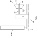
- the fuel system turboexpander section 80 is configured to mechanically power a mechanical load 96.
- the fuel system turboexpander rotor 95 of FIG. 1 is coupled to and rotatable with a rotor 98 of the mechanical load 96 through a drivetrain 100, which drivetrain 100 may be a geared drivetrain or a direct drive drivetrain as described above, for example.
- the driven rotor 98 may be the same as the propulsor rotor 12.
- Both the fuel system turboexpander rotor 95 and the low speed rotating assembly 64 of FIG. 4 are coupled to the propulsor rotor 12 through the geartrain 68.
- the driven rotor 98 may be discrete from the propulsor rotor 12.
- the driven rotor 98 of FIG. 1 may be configured as a generator rotor in an electric power generator (or more generally an electric machine). This electric power generator may supply electricity to one or more components of the engine system 10 and/or one or more other aircraft components outside of the engine system 10.
- the fuel accumulator 82 of FIG. 1 is configured as, or may otherwise include, a secondary fuel reservoir.
- This fuel accumulator 82 is configured to (e.g., temporarily) store a quantity of the fuel (e.g., in its gaseous phase) during engine system operation.
- the fuel accumulator 82 may also store the fuel before and/or after engine system operation. However, the quantity of the fuel stored by the fuel accumulator 82 is (e.g., significantly) less than the quantity of the fuel stored by the fuel reservoir 84 (when full).
- the fuel accumulator 82 may be configured as or otherwise include a tank, a cylinder, a pressure vessel, a bladder or any other type of fuel storage container.
- the fuel injectors 78 may be arranged circumferentially about the axis 24 in an array; e.g., a circular array.
- Each fuel injector 78 is configured to direct the fuel received from the fuel source 72 through the fuel flowpath 70 and metered by the fuel flow regulator 87, into the combustion chamber 36 for combustion.
- the fuel injectors 78 are schematically shown as discrete injectors, one or more of the fuel injectors 78 may alternatively be arcuate shaped, annular shaped or otherwise shaped and provided with multiple nozzle outlets; e.g., each fuel injector 78 may have a microjet configuration, a showerhead configuration or otherwise.
- the cooling circuit 18 extends longitudinally from an inlet 102 into the cooling circuit 18, through the cooling air heat exchanger 74 and its cooling air passage 90, to an outlet 104 from the cooling circuit 18.
- the circuit inlet 102 is configured to bleed core air from the core flowpath 30.
- This circuit inlet 102 may be located along the core flowpath 30 downstream of the compressor section 26 and upstream of the combustor 34.
- the circuit inlet 102 of FIG. 1 for example, is disposed along the plenum 32 and is configured to bleed some of the core air from the plenum 32 before that core air is directed into the combustion chamber 36.
- Each circuit outlet 104 is configured to deliver the bled core air - cooling air - to one or more components of the engine system 10 for cooling those system components.
- the circuit outlet 104 of FIG. 1 is configured to deliver the cooling air to one or more components within the turbine section 28; e.g., within the HPT section 28A and/or the LPT section 28B.
- the cooling circuit 18 may be configured to deliver the cooling air to an internal passage 106 (or passages) within the HPT rotor 54.
- the cooling circuit 18 may also or alternatively be configured to deliver the cooling air to an internal passage 108 (or passages) within (or a cooling plenum adjacent) a shroud 110; e.g., a blade outer air seal (BOAS) and/or a flowpath wall.
- This shroud 110 may form a peripheral boundary of at least a portion of the core flowpath 30 within the turbine section 28 (e.g., the HPT section 28A).
- the shroud 110 may also circumscribe the HPT rotor 54.
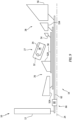
- the cooling circuit 18 may still also or alternatively be configured to deliver the cooling air to an internal passage 112 (or passages) within a stator vane array 114 (e.g., a turbine inlet vane array, a combustor exit vane array) between the combustor 34 (see FIG. 1 ) and the HPT rotor 54.
- a stator vane array 114 e.g., a turbine inlet vane array, a combustor exit vane array
- the fuel delivered by the fuel system 16 to the combustor section 27 and its combustor 34 may be a non-hydrocarbon fuel; e.g., a hydrocarbon free fuel.
- the fuel system 16 may direct hydrogen (H 2 ) fuel into the combustor 34 and into its combustion chamber 36.
- This hydrogen fuel may be stored within the fuel source 72 and its fuel reservoir 84 in a liquid phase.
- the fuel reservoir 84 in other words, may contain a quantity of the hydrogen fuel as liquid hydrogen (H 2 ).
- the hydrogen fuel may be injected or otherwise introduced into the combustion chamber 36 by the fuel injectors 78 in a gaseous phase.
- the fuel injectors 78 in other words, may direct the hydrogen fuel into the combustion chamber 36 as gaseous hydrogen; e.g., hydrogen (H 2 ) gas.
- the fuel system 16 directs a flow of the hydrogen fuel (completely or substantially in its liquid phase) into the cooling air heat exchanger 74.
- the cooling circuit 18 also directs a flow of the cooling air (e.g., core air bled from the core flowpath 30 / the plenum 32) into the cooling air heat exchanger 74.
- a temperature of the cooling air entering the cooling air heat exchanger 74 is (e.g., significantly) higher than a temperature of the hydrogen fuel entering the cooling air heat exchanger 74.
- the cooling air heat exchanger 74 may thereby transfer heat energy from the cooling air into the hydrogen fuel. This transfer of heat energy (heat transfer) from the cooling air to the hydrogen fuel cools the cooling air and heats the hydrogen fuel.
- the heating of the hydrogen fuel may facilitate a partial or complete phase change of the hydrogen fuel from the liquid phase to the gaseous phase.
- the cooling air may then be delivered to the turbine section 28 (e.g., the HPT section 28A) and its component(s) 54, 110, 114 (see FIG. 5 ) for air cooling those component(s) 54, 110, 114.
- the fuel system 16 directs the flow of the hydrogen fuel (completely or substantially in its gaseous phase) within the fuel flowpath 70 from the cooling air heat exchanger 74 into the combustion products heat exchanger 76.
- the engine core assembly 14 also directs a flow of gas - combustion products - into the combustion products heat exchanger 76 as described below in further detail.
- a temperature of the combustion products entering the combustion products heat exchanger 76 is (e.g., significantly) higher than a temperature of the hydrogen fuel entering the combustion products heat exchanger 76.
- the combustion products heat exchanger 76 may thereby transfer heat energy from the combustion products into the hydrogen fuel. This transfer of heat energy (heat transfer) from the combustion products to the hydrogen fuel cools the combustion products and further heats the hydrogen fuel.
- the heating of the hydrogen fuel may facilitate a complete phase change of the hydrogen fuel from the liquid phase to the gaseous phase. Moreover, the transfer of heat energy recuperates energy from the combustion products which may be utilized for powering the fuel system turboexpander section 80 and/or preparing the hydrogen fuel for combustion as described below.
- the fuel system 16 directs the heated hydrogen fuel (in its gaseous phase) within the fuel flowpath 70 from the combustion products heat exchanger 76 to the fuel system turboexpander section 80 for expansion across the fuel system turboexpander rotor 95.
- the expansion of the hydrogen fuel may drive rotation of the fuel system turboexpander rotor 95 about its rotational axis 116.
- the rotation of the fuel system turboexpander rotor 95 may drive rotation of the driven rotor 98; e.g., the propulsor rotor 12 or a generator rotor.
- the fuel system 16 subsequently directs the expanded hydrogen fuel within the fuel flowpath 70 from the fuel system turboexpander section 80, through the fuel accumulator 82, to the fuel injectors 78 for injection into the combustion chamber 36.
- air is directed across the propulsor rotor 12 and into the core flowpath 30.
- the air entering the core flowpath 30 may be referred to as the core air.
- This core air is compressed by the compressor rotors 52 before being diffused within the plenum 32 and directed into the combustor 34 and its combustion chamber 36.
- the hydrogen fuel supplied by the fuel injectors 78 and the compressed core air are mixed within the combustion chamber 36 to provide a fuel-air mixture.
- This fuel-air mixture is ignited and combustion products thereof flow through and sequentially cause the HPT rotor 54 and the LPT rotor 56 to rotate.
- the combustion products may then be directed through the combustion products heat exchanger 76 and exhausted from the engine system 10 through the core exhaust 40.
- the rotation of the HPT rotor 54 drives rotation of the compressor rotors 52 and, thus, compression of the air directed into the core flowpath 30 through the core inlet 38.
- the rotation of the LPT rotor 56 drives rotation of the propulsor rotor 12.
- the rotation of the propulsor rotor 12 may propel additional air (e.g., outside air) outside of and axially along the engine core assembly 14 (e.g., and the engine housing 22; see FIG. 2 ) to provide aircraft thrust.
- additional air e.g., outside air
- the propulsion of this additional air may account for a majority of the aircraft thrust generated by the engine system 10.
- the combustion products generated by the combustion of the fuel-air mixture within the combustion chamber 36 includes water (H 2 O) vapor.
- the recovery system 20 is configured to recover at least some of the water vapor produced by the combustion of the fuel-air mixture within the combustion chamber 36 and/or water vapor from water previously introduced into the core flowpath 30 as discussed below in further detail; e.g., water introduced for cooling, NOx reduction, etc.
- the recovery system 20 may also be configured to evaporate the recovered water using heat energy recuperated from the combustion products to provide steam for use in the engine core assembly 14; e.g., in the combustor section 27.
- the recovery system 20 of FIG. 2 includes one or more heat exchangers 118 and 120 and a water separator 122.
- the recovery system 20 may also include a water reservoir 124, a recovery system turboexpander section 126 and/or one or more flow regulators 128-130; e.g., compressors, pumps and/or valves.
- the condensing heat exchanger 118 (“condenser”) includes an internal combustion products passage 132 and an internal bypass air passage 134 which is fluidly discrete from the combustion products passage 132.
- the combustion products passage 132 forms a portion of the core flowpath 30 which extends longitudinally through the condenser 118.
- This portion of the core flowpath 30 formed by the combustion products passage 132 of FIG. 2 is arranged between the LPT rotor 56 and the core exhaust 40; e.g., within the exhaust section of the engine system 10.
- the condenser 118 is arranged along the core flowpath 30 downstream of the combustion products heat exchanger 76.
- the condenser 118 and its combustion products passage 132 may alternatively be arranged elsewhere along the core flowpath 30 downstream of the combustor section 27 in other embodiments.
- the combustion products heat exchanger 76 may be arranged along the core flowpath 30 downstream of the condenser 118.
- the bypass air passage 134 forms a portion of the bypass flowpath 48 which extends longitudinally through the condenser 118.
- the condenser 118 of FIG. 2 is schematically shown as a single pass, parallel flow heat exchanger. The condenser 118 of the present disclosure, however, is not limited to such an exemplary arrangement.
- the condenser 118 may alternatively be configured as counterflow heat exchanger or a crossflow heat exchanger or some hybridization or superposition of these general configurations.
- the combustion products passage 132 and/or the bypass air passage 134 may alternatively make two or more passes within the condenser 118.
- the evaporating heat exchanger 120 (“evaporator”) includes an internal combustion products passage 136 and an internal fluid (e.g., water-to-steam) passage 138 which is fluidly discrete from the combustion products passage 136.
- the combustion products passage 136 forms a portion of the core flowpath 30 which extends longitudinally through the evaporator 120. This portion of the core flowpath 30 formed by the combustion products passage 136 of FIG. 2 is arranged between the LPT rotor 56 and the core exhaust 40; e.g., within the exhaust section of the engine system 10.
- the evaporator 120 is arranged along the core flowpath 30 upstream of the combustion products heat exchanger 76 and/or the condenser 118.
- the evaporator 120 and its combustion products passage 136 may alternatively be arranged elsewhere along the core flowpath 30 downstream of the combustor section 27 in other embodiments.
- the evaporator 120 of FIG. 2 is schematically shown as a single pass, parallel flow heat exchanger.
- the evaporator 120 of the present disclosure is not limited to such an exemplary arrangement.
- the evaporator 120 may alternatively be configured as counterflow heat exchanger or a crossflow heat exchanger or some hybridization or superposition of these general configurations.
- the combustion products passage 136 and/or the fluid passage 138 may alternatively make two or more passes within the evaporator 120.
- the water separator 122 may be a passive water separator.
- the water separator 122 may be configured as or may otherwise include an impingement and/or condensation surface and a gutter arranged with and/or downstream of the condenser 118.
- various other types of separators are known in the art, and the present disclosure is not limited to any particular ones thereof.
- the present disclosure is not limited to passive water separator arrangements.
- the water separator 122 may alternatively be a centrifugal water separator or otherwise.
- the water reservoir 124 is configured to store a quantity of water before, during and/or after engine system operation.
- the water reservoir 124 may be configured as or otherwise include a tank, a cylinder, a pressure vessel, a bladder or any other type of water storage container.
- the recovery system turboexpander section 126 includes a bladed recovery system turboexpander rotor 140 (e.g., a steam driven turbine rotor).
- the recovery system turboexpander rotor 140 of FIG. 2 is configured as a radial flow turboexpander rotor; e.g., a radial inflow-axial outflow turboexpander rotor.
- the recovery system turboexpander rotor 140 includes a plurality of turbine blades (e.g., turbine airfoils, turbine vanes, etc.) arranged circumferentially around and connected to at least (or only) one rotor disk or hub.
- the present disclosure is not limited to the foregoing exemplary turboexpander section arrangement.
- the recovery system turboexpander section 126 may alternatively include multiple stages.
- the recovery system turboexpander rotor 140 is shown as a radial flow turboexpander rotor, the recovery system turboexpander rotor 140 may alternatively be configured as an axial flow turboexpander rotor.
- the recovery system turboexpander section 126 is configured to mechanically power a mechanical load 142.
- the recovery system turboexpander rotor 140 of FIG. 2 is coupled to and rotatable with a rotor 144 of the mechanical load 142 through a drivetrain 146, which drivetrain 146 may be a geared drivetrain or a direct drive drivetrain as described above, for example.
- the driven rotor 144 may be the same as the propulsor rotor 12.
- Both the recovery system turboexpander rotor 140 and the low speed rotating assembly 64 of FIG. 6 are coupled to the propulsor rotor 12 through the geartrain 68.
- the driven rotor 144 may be discrete from the propulsor rotor 12.
- the driven rotor 144 of FIG. 2 may be configured as a generator rotor in an electric power generator (or more generally an electric machine). This electric power generator may supply electricity to one or more components of the engine system 10 and/or one or more other aircraft components outside of the engine system 10.
- An inlet to the water reservoir 124 is fluidly coupled with an outlet from the water separator 122 through, for example, the first flow regulator 128.
- An outlet from the water reservoir 124 is fluidly coupled with one or more components 148 of the engine core assembly 14 through, for example, the second flow regulator 129.
- One or more of the turbine engine components 148 may each be configured as or otherwise include a water injector. Each water injector may be configured to provide the water to the compressor section 26; e.g., for injection into the core flowpath 30.
- the present disclosure is not limited to the foregoing exemplary turbine engine components which utilize the water. In particular, various other uses for water in a turbine engine are known in the art, and the present disclosure is not limited to any particular one thereof.
- the outlet from the water reservoir 124 is also fluidly coupled with an inlet into the evaporator 120 and its fluid passage 138 through the third flow regulator 130.
- An outlet from the evaporator 120 and its fluid passage 138 is fluidly coupled with one or more additional components 150 of the engine core assembly 14 through, for example, the recovery system turboexpander section 126.
- One or more of the turbine engine components 150 may each be configured as or otherwise include a steam injector. Each steam injector may be configured to provide the steam to the combustor section 27; e.g., for injection into the core flowpath 30 / the combustion chamber 36.
- the present disclosure is not limited to the foregoing exemplary turbine engine components which utilize the steam. In particular, various other uses for steam in a turbine engine are known in the art, and the present disclosure is not limited to any particular one thereof.
- the engine core assembly 14 directs a flow of the combustion products into the condenser 118 and its combustion products passage 132.
- the bypass flowpath 48 also directs a flow of bypass air (air flowing within the bypass flowpath 48 and bypassing the engine core assembly 14) into the condenser 118 and its bypass air passage 134.
- a temperature of the combustion products entering the condenser 118 is (e.g., significantly) higher than a temperature of the bypass air entering the condenser 118.
- the condenser 118 may thereby transfer heat energy from the combustion products into the bypass air. This transfer of heat energy (heat transfer) from the combustion products to the bypass air cools the combustion products and heats the bypass air.
- the cooling of the combustion products may facilitate condensation of the water vapor in the combustion products into droplets of water. This water is collected by the water separator 122 and directed through the first flow regulator 128 into the water reservoir 124.
- At least some of the water stored within the water reservoir 124 may be directed to the engine components 148 through the second flow regulator 129.
- This second flow regulator 129 may meter or otherwise regulate (e.g., turn on or off) the flow of the water from the water reservoir 124 to the engine components 148.
- At least some of the water stored within the water reservoir 124 may also or alternatively be directed into the evaporator 120 and its fluid passage 138 through the third flow regulator 130.
- This third flow regulator 130 may meter or otherwise regulate (e.g., turn on or off) the flow of the water from the water reservoir 124 to the evaporator 120.
- the engine core assembly 14 also directs a flow of the combustion products into the evaporator 120 and its combustion products passage 136.
- a temperature of the combustion products entering the evaporator 120 is (e.g., significantly) higher than a temperature of the water entering the evaporator 120.
- the evaporator 120 may thereby transfer heat energy from the combustion products into the water.
- This transfer of heat energy (heat transfer) from the combustion products to the water cools the combustion products and heats the water.
- the heating of the water may facilitate evaporation and/or superheating of at least some or all of the water into steam.
- This (e.g., superheated) steam is directed through the recovery system turboexpander section 126 to the engine components 150.
- the steam is expanded across the recovery system turboexpander rotor 140. This expansion of the steam may drive rotation of the recovery system turboexpander rotor 140 about its rotational axis 152.
- the rotation of the recovery system turboexpander rotor 140 may drive rotation of the driven rotor 144; e.g., the propulsor rotor 12 or a generator rotor.
- the engine system 10 of FIG. 1 and its fuel system 16 are described above with multiple heat exchangers 74 and 76. It is contemplated, however, any one or more of the heat exchangers 74, 76 may be omitted depending on engine system parameters and/or requirements. The present disclosure therefore is not limited to the exemplary fuel system arrangement of FIG. 1 .
- the fuel-combustion products heat exchanger 76 may be configured discrete from the condensing heat exchanger 118. In such embodiments, the fuel-combustion products heat exchanger 76 may be arranged upstream of the condensing heat exchanger 118 along the core flowpath 30. Alternatively, referring to FIG. 7 , the condensing heat exchanger 118 may be arranged upstream of the fuel-combustion products heat exchanger 76 along the core flowpath 30. The fuel-combustion products heat exchanger 76 of FIG. 7 , for example, is arranged between the condensing heat exchanger 118 and the water separator 122. In other embodiments, referring to FIG. 8 , the fuel-combustion products heat exchanger 76 and the condensing heat exchanger 118 may be integrated in to a single (e.g., multifunction) heat exchanger structure.
- the engine core assembly 14 is shown in FIG. 1 with two rotating assemblies 60 and 64. It is contemplated, however, the engine core assembly 14 may alternatively be configured with a single rotating assembly, or with three or more rotating assemblies.
- the engine core assembly 14 of FIG. 9 is configured with an additional turbine rotor 154 (e.g., an intermediate pressure turbine (IPT) rotor) coupled to and configured to drive rotation of the compressor rotor 52A.
- IPT intermediate pressure turbine
Landscapes
- Engineering & Computer Science (AREA)
- Chemical & Material Sciences (AREA)
- Combustion & Propulsion (AREA)
- Mechanical Engineering (AREA)
- General Engineering & Computer Science (AREA)
- Engine Equipment That Uses Special Cycles (AREA)
- Structures Of Non-Positive Displacement Pumps (AREA)
Abstract
Description
- This disclosure relates generally to an aircraft and, more particularly, to a turbine engine system for the aircraft.
- There is interest in alternative fuels for gas turbine engines. There is interest, for example, in fueling a gas turbine engine with hydrogen rather than a traditional hydrocarbon fuel such as kerosine to reduce greenhouse emissions. Various systems and methods are known in the art for fueling a gas turbine engine with hydrogen. While these known systems and methods have various advantages, there is still room in the art for improvement.
- According to an aspect of the present invention, an engine system is provided that includes an open propulsor rotor, an engine core assembly, a bypass flowpath and a condenser. The engine core assembly is configured to drive rotation of the open propulsor rotor. The engine core assembly includes a core flowpath, a compressor section, a combustor section and a turbine section. The core flowpath extends through the compressor section, the combustor section and the turbine section from an inlet into the core flowpath to an exhaust from the core flowpath. The bypass flowpath bypasses the engine core assembly. The condenser is configured to exchange heat energy between combustion products flowing within the core flowpath downstream of the combustor section and bypass air flowing within the bypass flowpath.
- According to another aspect of the present invention, another engine system is provided that includes an engine core assembly, a recovery system and a fuel system. The engine core assembly includes a core flowpath, a compressor section, a combustor section and a turbine section. The core flowpath extends through the compressor section, the combustor section and the turbine section from an inlet into the core flowpath to an exhaust from the core flowpath. The combustor section includes a combustor. The recovery system includes an evaporator and a recovery system turboexpander section. The evaporator is configured to exchange heat energy between combustion products flowing within the core flowpath downstream of the combustor section and water flowing within the recovery system to evaporate the water into steam. The recovery system turboexpander section includes a recovery system turboexpander rotor. The recovery system is configured to expand at least some of the steam across the recovery system turboexpander section to drive rotation of the recovery system turboexpander rotor. The fuel system includes a fuel flowpath, a fuel injector and a fuel system turboexpander section. The fuel flowpath is configured to direct fuel through the fuel system turboexpander section to the fuel injector. The fuel injector is configured to introduce the fuel into the combustor. The fuel system turboexpander section includes a fuel system turboexpander rotor. The fuel system is configured to expand the fuel flowing within the fuel flowpath across the fuel system turboexpander section to drive rotation of the fuel system turboexpander rotor.
- According to still another aspect of the present invention, another engine system is provided that includes an un-ducted propulsor rotor, an engine core assembly, a fuel system, an internal second flowpath and a heat exchanger. The engine core assembly is configured to drive rotation of the un-ducted propulsor rotor. The engine core assembly includes a core flowpath, a compressor section, a combustor section and a turbine section. The core flowpath extends through the compressor section, the combustor section and the turbine section from an inlet into the core flowpath to an exhaust from the core flowpath. The combustor section includes a combustor. The fuel system includes a fuel flowpath and a fuel injector. The fuel flowpath is configured to direct hydrogen fuel to the fuel injector. The fuel injector is configured to introduce the hydrogen fuel into the combustor. The internal second flowpath extends around the engine core assembly. The heat exchanger is configured to exchange heat energy between a working fluid and air flowing within the internal second flowpath.
- The following optional features may be applied to any of the above aspects.
- The working fluid may be combustion products flowing within the core flowpath downstream of the turbine section.
- The engine system may also include an un-ducted propulsor rotor. At least one of the engine core assembly, the recovery system turboexpander rotor or the fuel system turboexpander rotor may be configured to drive rotation of the un-ducted propulsor rotor.
- The engine system may also include a water separator. The condenser may be configured to condense water vapor flowing through the core flowpath into water. The water separator may be configured to collect the water within the core flowpath.
- The engine system may also include a water reservoir fluidly coupled with the water separator. The water reservoir may be configured to store at least some of the water.
- The engine system may also include a water recovery system including the condenser and the water separator. The water recovery system may be configured to direct at least some of the water to the engine core assembly.
- The engine system may also include a water recovery system including the condenser, the water separator and an evaporator. The evaporator may be configured to evaporate at least some of the water into steam. The water recovery system may be configured to direct at least some of the steam to the engine core assembly.
- The engine system may also include an evaporator configured to exchange heat energy between the combustion products flowing within the core flowpath and at least some of the water to evaporate the at least some of the water into steam.
- The core flowpath may extend from the turbine section, through the evaporator and the condenser, to the exhaust from the core flowpath.
- The engine system may also include a turboexpander section including a turboexpander rotor. The turboexpander section may be configured to expand at least some of the steam across the turboexpander rotor to drive rotation of the turboexpander rotor.
- The turboexpander rotor may be configured to further drive rotation of the open propulsor rotor.
- The engine system may also include a mechanical load mechanically powered by the turboexpander section.
- The engine system may also include a fuel system including a fuel reservoir, a fuel flowpath and a fuel injector. The fuel flowpath may be configured to direct hydrogen fuel, received from the fuel reservoir, to the fuel injector. The fuel injector may be configured to introduce the hydrogen fuel into a combustor of the combustor section.
- The fuel reservoir may be configured to contain a quantity of the hydrogen fuel in a liquid phase. The fuel system may be configured to direct the hydrogen fuel into the combustor in a gaseous phase through the fuel injector.
- The engine system may also include a fuel system and a cooling circuit. The fuel system may include a fuel flowpath, a fuel-cooling air heat exchanger and a fuel injector. The fuel flowpath may be configured to direct fuel through the fuel-cooling air heat exchanger to the fuel injector. The fuel injector may be configured to introduce the fuel into a combustor of the combustor section. The cooling circuit may be configured to direct cooling air through the fuel-cooling air heat exchanger to the engine core assembly. The fuel-cooling air heat exchanger may be configured to exchange heat energy between the fuel flowing within the fuel flowpath and the cooling air flowing within the cooling circuit.
- The cooling circuit may be configured to bleed core air from the core flowpath upstream of the combustor to provide the cooling air.
- The cooling circuit may be configured to direct the cooling air to the turbine section.
- The engine system may also include a fuel system including a fuel flowpath, a fuel-combustion products heat exchanger and a fuel injector. The fuel flowpath may be configured to direct fuel through the fuel-combustion products heat exchanger to the fuel injector. The fuel injector may be configured to introduce the fuel into a combustor of the combustor section. The fuel-combustion products heat exchanger may be configured to exchange heat energy between the fuel flowing within the fuel flowpath and the combustion products flowing within the core flowpath.
- The fuel-combustion products heat exchanger may be downstream of the condenser along the core flowpath.
- The fuel-combustion products heat exchanger may be upstream of the condenser along the core flowpath.
- The fuel-combustion products heat exchanger may be integrated with the condenser along the core flowpath.
- The engine system may also include a fuel system including a fuel flowpath, a fuel injector and a turboexpander section. The fuel flowpath may be configured to direct fuel through the turboexpander section to the fuel injector. The fuel injector may be configured to introduce the fuel into a combustor of the combustor section. The turboexpander section may include a turboexpander rotor. The fuel system may be configured to expand the fuel flowing within the fuel flowpath across the turboexpander section to drive rotation of the turboexpander rotor.
- The turboexpander rotor may be configured to further drive rotation of the open propulsor rotor.
- The engine system may also include a mechanical load mechanically powered by the turboexpander section.
- The engine system may also include a fuel system including a fuel flowpath, an accumulator and a fuel injector. The fuel flowpath may be configured to direct fuel through the accumulator to the fuel injector. The fuel injector may be configured to introduce the fuel into a combustor of the combustor section.
- The open propulsor rotor may be configured as or otherwise include a propeller rotor.
- The present disclosure may include any one or more of the individual features disclosed above and/or below alone or in any combination thereof.
- The foregoing features and the operation of the invention will become more apparent in light of the following description and the accompanying drawings.
-
-
FIG. 1 is a partial schematic illustration of a gas turbine engine system for an aircraft. -
FIG. 2 is another partial schematic illustration of the gas turbine engine system. -
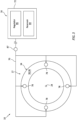
FIG. 3 is a partial schematic illustration of a fuel system arranged with a combustor section. -
FIG. 4 is a partial schematic illustration of a fuel system turboexpander and a core rotating assembly coupled to a common mechanical load. -
FIG. 5 is a partial schematic illustration of a cooling circuit delivering cooling air to one or more components within a turbine section. -
FIG. 6 is a partial schematic illustration of a water recovery system turboexpander and the core rotating assembly coupled to a common mechanical load. -
FIGS. 7 and 8 are schematic illustrations of various arrangements of heat exchangers along a core flowpath. -
FIG. 9 is a partial schematic illustration of the gas turbine engine with three rotating assemblies. -
FIG. 1 illustrates a gasturbine engine system 10 for an aircraft. The aircraft may be an airplane, a helicopter, a drone (e.g., an unmanned aerial vehicle (UAV)) or any other manned or unmanned aerial vehicle or system. Theengine system 10 ofFIG. 1 is configured as, or otherwise included as part of, an open rotor propulsion system for the aircraft. Thisengine system 10 includes anopen propulsor rotor 12, anengine core assembly 14 and afuel system 16. Theengine system 10 may also include acooling circuit 18 and/or a water recovery system 20 (see alsoFIG. 2 ). - The
propulsor rotor 12 is configured as an open, un-ducted air mover for the aircraft propulsion system. Examples of thepropulsor rotor 12 include a propeller rotor for a turboprop propulsion system, a rotorcraft rotor (e.g., a main helicopter rotor) for a turboshaft propulsion system, a propfan rotor for a propfan propulsion system, a pusher fan rotor for a pusher fan propulsion system, or any other type of un-ducted propulsor rotor. Thepropulsor rotor 12 includes a rotor disk (or hub) and a plurality of open, un-ducted propulsor blades arranged circumferentially around and connected to the rotor disk (or hub). Referring toFIG. 2 , thepropulsor rotor 12 and its propulsor blades are disposed outside of anengine housing 22 of theengine system 10. For ease of description, thepropulsor rotor 12 may be generally described below as the propeller rotor for the turboprop propulsion system. The present disclosure, however, is not limited to such an arrangement. Moreover, it is contemplated theopen propulsor rotor 12 may be replaced by a ducted propulsor rotor (e.g., a fan rotor, a compressor rotor, etc.) or a rotor for another type of mechanical load (e.g., a generator rotor for an electric power generator) in other embodiments. - The
engine core assembly 14 is housed within theengine housing 22. Referring toFIG. 1 , theengine core assembly 14 extends axially along anaxis 24 between an upstream, forward end of theengine core assembly 14 and a downstream, aft end of theengine core assembly 14. Theengine core assembly 14 includes acore compressor section 26, acore combustor section 27, acore turbine section 28 and acore flowpath 30. Thecombustor section 27 includes a plenum 32 (e.g., a diffuser plenum) and a combustor 34 (e.g., an annular combustor). Briefly, thecombustor 34 includes an internal combustion chamber 36 (e.g., an annular combustion chamber), and is disposed within or otherwise adjacent theplenum 32. Theturbine section 28 ofFIG. 1 includes a high pressure turbine (HPT)section 28A and a low pressure turbine (LPT)section 28B; e.g., a power turbine (PT) section. Thecore flowpath 30 extends sequentially through thecompressor section 26, the combustor section 27 (e.g., sequentially through theplenum 32 and the combustion chamber 36), theHPT section 28A and theLPT section 28B from anairflow inlet 38 into thecore flowpath 30 to a combustion products exhaust 40 from thecore flowpath 30. Thecore inlet 38 may be disposed at (e.g., on, adjacent or proximate) the assembly forward end, and thecore exhaust 40 may be disposed at the assembly aft end. - Referring to
FIG. 2 , thecore flowpath 30 and itscore inlet 38 may be fluidly coupled with and downstream of aninlet duct 42 of theengine system 10. Thisinlet duct 42 is disposed within theengine housing 22 and is configured to direct air entering theengine system 10 from anenvironment 44 external to the aircraft (e.g., an outside, ambient environment) to thecore inlet 38 and aninlet 46 into abypass flowpath 48. Thebypass flowpath 48 is also disposed within theengine housing 22. Thebypass flowpath 48, however, bypass theengine core assembly 14 and, in particular, its engine sections 26-28B. Thebypass flowpath 48 ofFIG. 2 , for example, extends from itsbypass inlet 46, internally through theengine system 10, to anairflow exhaust 50 from thebypass flowpath 48. Here, thebypass exhaust 50 and thecore exhaust 40 ofFIG. 2 are discretely fluidly coupled to theexternal environment 44. The present disclosure, however, is not limited to such an exemplary arrangement. For example, in other embodiments, thecore flowpath 30 and thebypass flowpath 48 may discretely receive air from theexternal environment 44. In addition or alternatively, thecore flowpath 30 and thebypass flowpath 48 may be fluidly coupled to theexternal environment 44 through a common exhaust. - Referring to
FIG. 1 , thecompressor section 26 includes one or morebladed compressor rotors stage compressor rotor 52A ofFIG. 1 is configured as an axial flow compressor rotor; e.g., an axial inflow-axial outflow compressor rotor. The secondstage compressor rotor 52B ofFIG. 1 is configured as a radial flow compressor rotor; e.g., an axial inflow-radial outflow compressor rotor. Each of these compressor rotors 52 includes a plurality of compressor blades (e.g., compressor airfoils, compressor vanes, etc.) arranged circumferentially around and connected to at least (or only) one rotor disk or hub. The compressor rotors 52 are disposed in and arranged longitudinally along thecore flowpath 30 between thecore inlet 38 and thecombustor section 27. The compressor blades, for example, are disposed in and extend across thecore flowpath 30. Each rotor disk or hub is disposed adjacent (e.g., radially below) thecore flowpath 30. The present disclosure, however, is not limited to the foregoing exemplary compressor section arrangement. For example, while thecompressor section 26 is schematically shown inFIG. 1 with two stages, thecompressor section 26 may alternatively include a single one of the stages or more than two stages. Moreover, while the compressor rotors 52 are respectively shown as axial and radial flow compressor rotors, any one or more of the compressor rotors 52 may alternatively be configured as an axial flow compressor rotor or a radial flow compressor rotor. - The
HPT section 28A includes a blade high pressure turbine (HPT)rotor 54. TheHPT rotor 54 ofFIG. 1 is configured as an axial flow turbine rotor; e.g., an axial inflow-axial outflow turbine rotor. TheHPT rotor 54 includes a plurality of turbine blades (e.g., turbine airfoils, turbine vanes, etc.) arranged circumferentially around and connected to at least (or only) one rotor disk or hub. TheHPT rotor 54 is disposed in and arranged longitudinally along thecore flowpath 30 between the combustor 34 and theLPT section 28B. The turbine blades, for example, are disposed in and extend across thecore flowpath 30. The rotor disk or hub is disposed adjacent (e.g., radially below) thecore flowpath 30. The present disclosure, however, is not limited to the foregoing exemplary HPT section arrangement. For example, while theHPT section 28A is schematically shown inFIG. 1 with a single stage, theHPT section 28A may alternatively include multiple stages. Moreover, while theHPT rotor 54 is shown as an axial flow turbine rotor, theHPT rotor 54 may alternatively be configured as a radial flow turbine rotor. - The
LPT section 28B includes a blade low pressure turbine (LPT)rotor 56. TheLPT rotor 56 ofFIG. 1 is configured as an axial flow turbine rotor; e.g., an axial inflow-axial outflow turbine rotor. TheLPT rotor 56 includes a plurality of turbine blades (e.g., turbine airfoils, turbine vanes, etc.) arranged circumferentially around and connected to at least (or only) one rotor disk or hub. TheLPT rotor 56 is disposed in and arranged longitudinally along thecore flowpath 30 between theHPT section 28A and thecore exhaust 40. The turbine blades, for example, are disposed in and extend across thecore flowpath 30. The rotor disk or hub is disposed adjacent (e.g., radially below) thecore flowpath 30. The present disclosure, however, is not limited to the foregoing exemplary LPT section arrangement. For example, while theLPT section 28B is schematically shown inFIG. 1 with a single stage, theLPT section 28B may alternatively include multiple stages. Moreover, while theLPT rotor 56 is shown as an axial flow turbine rotor, theLPT rotor 56 may alternatively be configured as a radial flow turbine rotor. - The compressor rotors 52 are coupled to and rotatable with the
HPT rotor 54. The compressor rotors 52 ofFIG. 1 , for example, are connected to theHPT rotor 54 by ahigh speed shaft 58. At least (or only) the compressor rotors 52, theHPT rotor 54 and thehigh speed shaft 58 collectively form a highspeed rotating assembly 60; e.g., a high speed spool. TheLPT rotor 56 is connected to alow speed shaft 62. At least (or only) theLPT rotor 56 and thelow speed shaft 62 collectively form a lowspeed rotating assembly 64. This lowspeed rotating assembly 64 is further coupled to thepropulsor rotor 12 through adrivetrain 66. Thisdrivetrain 66 may be configured as a geared drivetrain, where a geartrain 68 (e.g., a transmission, a speed change device, an epicyclic geartrain, etc.) is disposed between and operatively couples thepropulsor rotor 12 to the lowspeed rotating assembly 64 and itsLPT rotor 56. With this arrangement, thepropulsor rotor 12 may rotate at a different (e.g., slower) rotational velocity than the lowspeed rotating assembly 64 and itsLPT rotor 56. However, thedrivetrain 66 may alternatively be configured as a direct drive drivetrain, where thegeartrain 68 is omitted. With this arrangement, thepropulsor rotor 12 rotates at a common (the same) rotational velocity as the lowspeed rotating assembly 64 and itsLPT rotor 56. Referring again toFIG. 1 , each of therotating assemblies members axis 24. Theaxis 24 may thereby be a rotational axis and/or a centerline axis of therotating assemblies members - The
fuel system 16 includes afuel flowpath 70, afuel source 72, one ormore heat exchangers FIG. 3 ). Thefuel system 16 ofFIG. 1 also includes a fuel system turboexpander section 80 (e.g., a fuel driven turbine section) and/or afuel accumulator 82. Thefuel flowpath 70 is fluidly coupled with an outlet from thefuel source 72 and an inlet to eachfuel injector 78. Thisfuel flowpath 70 extends from thefuel source 72 and its outlet, sequentially through the fuel-cooling air heat exchanger 74 ("cooling air heat exchanger") (e.g., a compressor bleed air cooler, a turbine cooling air cooler, etc.), the fuel-combustion products heat exchanger 76 ("combustion products heat exchanger") (e.g., a recuperator for the core flowpath 30), the fuelsystem turboexpander section 80 and thefuel accumulator 82, to eachfuel injector 78 and its inlet. - The
fuel source 72 ofFIG. 1 includes afuel reservoir 84 and afuel flow regulator 86. Thefuel reservoir 84 is configured to store a quantity of fuel (e.g., in its liquid phase) before, during and/or after engine system operation. Thefuel reservoir 84, for example, may be configured as or otherwise include a tank, a cylinder, a pressure vessel, a bladder or any other type of (e.g., insulated) fuel storage container. Thefuel flow regulator 86 is configured to direct a flow of the fuel from thefuel reservoir 84 to one or more or all of thefuel injectors 78 through thefuel flowpath 70. Thefuel flow regulator 86, for example, may be configured as or otherwise include a fuel compressor, a fuel pump and/or a fuel valve (or valves). Thefuel system 16 may also include an additionalfuel flow regulator 87 downstream of thefuel accumulator 82 to direct and/or meter the flow of fuel to theengine core assembly 14. - The cooling
air heat exchanger 74 includes aninternal fuel passage 88 and an internalcooling air passage 90 which is fluidly discrete from thefuel passage 88. Thefuel passage 88 forms a portion of thefuel flowpath 70 which extends longitudinally through the coolingair heat exchanger 74. The coolingair passage 90 forms a portion of thecooling circuit 18 which extends longitudinally through the coolingair heat exchanger 74. The coolingair heat exchanger 74 ofFIG. 1 is schematically shown as a single pass, parallel flow heat exchanger. The coolingair heat exchanger 74 of the present disclosure, however, is not limited to such an exemplary arrangement. The coolingair heat exchanger 74, for example, may alternatively be configured as cross flow heat exchanger or a counterflow heat exchanger or some hybridization or superposition of these general configurations. Moreover, thefuel passage 88 and/or the coolingair passage 90 may alternatively make two or more passes within the coolingair heat exchanger 74. - The combustion
products heat exchanger 76 includes aninternal fuel passage 92 and an internalcombustion products passage 94 which is fluidly discrete from thefuel passage 92. Thefuel passage 92 forms a portion of thefuel flowpath 70 which extends longitudinally through the combustionproducts heat exchanger 76. Thecombustion products passage 94 forms a portion of thecore flowpath 30 which extends longitudinally through the combustionproducts heat exchanger 76. This portion of thecore flowpath 30 formed by thecombustion products passage 94 ofFIG. 1 is arranged between theLPT rotor 56 and thecore exhaust 40; e.g., within an exhaust section of theengine system 10. However, the combustionproducts heat exchanger 76 and itscombustion products passage 94 may alternatively be arranged elsewhere along thecore flowpath 30 downstream of thecombustor section 27 in other embodiments. The combustionproducts heat exchanger 76 ofFIG. 1 is schematically shown as a single pass, cross flow heat exchanger. The combustionproducts heat exchanger 76 of the present disclosure, however, is not limited to such an exemplary arrangement. The combustionproducts heat exchanger 76, for example, may alternatively be configured as parallel flow heat exchanger or a counterflow heat exchanger or some hybridization or superposition of these general configurations. Moreover, thefuel passage 92 and/or thecombustion products passage 94 may alternatively make two or more passes within the combustionproducts heat exchanger 76. - The fuel
system turboexpander section 80 includes a bladed fuel system turboexpander rotor 95 (e.g., a fuel driven turbine rotor). The fuelsystem turboexpander rotor 95 ofFIG. 1 is configured as a radial flow turboexpander rotor; e.g., a radial inflow-axial outflow turboexpander rotor. The fuelsystem turboexpander rotor 95 includes a plurality of turbine blades (e.g., turbine airfoils, turbine vanes, etc.) arranged circumferentially around and connected to at least (or only) one rotor disk or hub. The fuelsystem turboexpander rotor 95 ofFIG. 1 is disposed in and arranged longitudinally along thefuel flowpath 70 between (a) one or more of thefuel system members fuel system members 78 and/or 82. The turbine blades, for example, are disposed in and extend across thefuel flowpath 70. The rotor disk or hub is disposed adjacent (e.g., radially below) thefuel flowpath 70. The present disclosure, however, is not limited to the foregoing exemplary turboexpander section arrangement. For example, while the fuelsystem turboexpander section 80 is shown inFIG. 1 with a single stage, the fuelsystem turboexpander section 80 may alternatively include multiple stages. Moreover, while the fuelsystem turboexpander rotor 95 is shown as a radial flow turboexpander rotor, the fuelsystem turboexpander rotor 95 may alternatively be configured as an axial flow turboexpander rotor. - The fuel
system turboexpander section 80 is configured to mechanically power amechanical load 96. The fuelsystem turboexpander rotor 95 ofFIG. 1 , for example, is coupled to and rotatable with arotor 98 of themechanical load 96 through adrivetrain 100, whichdrivetrain 100 may be a geared drivetrain or a direct drive drivetrain as described above, for example. Referring toFIG. 4 , the drivenrotor 98 may be the same as thepropulsor rotor 12. Both the fuelsystem turboexpander rotor 95 and the lowspeed rotating assembly 64 ofFIG. 4 , for example, are coupled to thepropulsor rotor 12 through thegeartrain 68. Thus, energy may be extracted from the fuel as described below in further detail to boost mechanical drive power to thepropulsor rotor 12. Alternatively, referring again toFIG. 1 , the drivenrotor 98 may be discrete from thepropulsor rotor 12. The drivenrotor 98 ofFIG. 1 , for example, may be configured as a generator rotor in an electric power generator (or more generally an electric machine). This electric power generator may supply electricity to one or more components of theengine system 10 and/or one or more other aircraft components outside of theengine system 10. - The
fuel accumulator 82 ofFIG. 1 is configured as, or may otherwise include, a secondary fuel reservoir. Thisfuel accumulator 82 is configured to (e.g., temporarily) store a quantity of the fuel (e.g., in its gaseous phase) during engine system operation. Thefuel accumulator 82 may also store the fuel before and/or after engine system operation. However, the quantity of the fuel stored by thefuel accumulator 82 is (e.g., significantly) less than the quantity of the fuel stored by the fuel reservoir 84 (when full). Thefuel accumulator 82 ofFIG. 1 , for example, is configured to provide a temporary supply of the fuel for startup of theengine system 10 and/or for balancing out (e.g., evening out) possible fluctuations of fuel flow within thefuel flowpath 70. Thefuel accumulator 82 may be configured as or otherwise include a tank, a cylinder, a pressure vessel, a bladder or any other type of fuel storage container. - Referring to
FIG. 3 , thefuel injectors 78 may be arranged circumferentially about theaxis 24 in an array; e.g., a circular array. Eachfuel injector 78 is configured to direct the fuel received from thefuel source 72 through thefuel flowpath 70 and metered by thefuel flow regulator 87, into thecombustion chamber 36 for combustion. Note, while thefuel injectors 78 are schematically shown as discrete injectors, one or more of thefuel injectors 78 may alternatively be arcuate shaped, annular shaped or otherwise shaped and provided with multiple nozzle outlets; e.g., eachfuel injector 78 may have a microjet configuration, a showerhead configuration or otherwise. - Referring to
FIG. 1 , the coolingcircuit 18 extends longitudinally from aninlet 102 into thecooling circuit 18, through the coolingair heat exchanger 74 and itscooling air passage 90, to anoutlet 104 from the coolingcircuit 18. Thecircuit inlet 102 is configured to bleed core air from thecore flowpath 30. Thiscircuit inlet 102 may be located along thecore flowpath 30 downstream of thecompressor section 26 and upstream of thecombustor 34. Thecircuit inlet 102 ofFIG. 1 , for example, is disposed along theplenum 32 and is configured to bleed some of the core air from theplenum 32 before that core air is directed into thecombustion chamber 36. Eachcircuit outlet 104, on the other hand, is configured to deliver the bled core air - cooling air - to one or more components of theengine system 10 for cooling those system components. Thecircuit outlet 104 ofFIG. 1 , for example, is configured to deliver the cooling air to one or more components within theturbine section 28; e.g., within theHPT section 28A and/or theLPT section 28B. For example, referring toFIG. 5 , the coolingcircuit 18 may be configured to deliver the cooling air to an internal passage 106 (or passages) within theHPT rotor 54. Thecooling circuit 18 may also or alternatively be configured to deliver the cooling air to an internal passage 108 (or passages) within (or a cooling plenum adjacent) ashroud 110; e.g., a blade outer air seal (BOAS) and/or a flowpath wall. Thisshroud 110 may form a peripheral boundary of at least a portion of thecore flowpath 30 within the turbine section 28 (e.g., theHPT section 28A). Theshroud 110 may also circumscribe theHPT rotor 54. Thecooling circuit 18 may still also or alternatively be configured to deliver the cooling air to an internal passage 112 (or passages) within a stator vane array 114 (e.g., a turbine inlet vane array, a combustor exit vane array) between the combustor 34 (seeFIG. 1 ) and theHPT rotor 54. - Referring again to
FIG. 1 , the fuel delivered by thefuel system 16 to thecombustor section 27 and itscombustor 34 may be a non-hydrocarbon fuel; e.g., a hydrocarbon free fuel. Thefuel system 16, for example, may direct hydrogen (H2) fuel into thecombustor 34 and into itscombustion chamber 36. This hydrogen fuel may be stored within thefuel source 72 and itsfuel reservoir 84 in a liquid phase. Thefuel reservoir 84, in other words, may contain a quantity of the hydrogen fuel as liquid hydrogen (H2). The hydrogen fuel, however, may be injected or otherwise introduced into thecombustion chamber 36 by thefuel injectors 78 in a gaseous phase. Thefuel injectors 78, in other words, may direct the hydrogen fuel into thecombustion chamber 36 as gaseous hydrogen; e.g., hydrogen (H2) gas. - During engine system operation, the
fuel system 16 directs a flow of the hydrogen fuel (completely or substantially in its liquid phase) into the coolingair heat exchanger 74. Thecooling circuit 18 also directs a flow of the cooling air (e.g., core air bled from thecore flowpath 30 / the plenum 32) into the coolingair heat exchanger 74. Here, a temperature of the cooling air entering the coolingair heat exchanger 74 is (e.g., significantly) higher than a temperature of the hydrogen fuel entering the coolingair heat exchanger 74. The coolingair heat exchanger 74 may thereby transfer heat energy from the cooling air into the hydrogen fuel. This transfer of heat energy (heat transfer) from the cooling air to the hydrogen fuel cools the cooling air and heats the hydrogen fuel. The heating of the hydrogen fuel may facilitate a partial or complete phase change of the hydrogen fuel from the liquid phase to the gaseous phase. The cooling air may then be delivered to the turbine section 28 (e.g., theHPT section 28A) and its component(s) 54, 110, 114 (seeFIG. 5 ) for air cooling those component(s) 54, 110, 114. - The
fuel system 16 directs the flow of the hydrogen fuel (completely or substantially in its gaseous phase) within thefuel flowpath 70 from the coolingair heat exchanger 74 into the combustionproducts heat exchanger 76. Theengine core assembly 14 also directs a flow of gas - combustion products - into the combustionproducts heat exchanger 76 as described below in further detail. Here, a temperature of the combustion products entering the combustionproducts heat exchanger 76 is (e.g., significantly) higher than a temperature of the hydrogen fuel entering the combustionproducts heat exchanger 76. The combustionproducts heat exchanger 76 may thereby transfer heat energy from the combustion products into the hydrogen fuel. This transfer of heat energy (heat transfer) from the combustion products to the hydrogen fuel cools the combustion products and further heats the hydrogen fuel. The heating of the hydrogen fuel may facilitate a complete phase change of the hydrogen fuel from the liquid phase to the gaseous phase. Moreover, the transfer of heat energy recuperates energy from the combustion products which may be utilized for powering the fuelsystem turboexpander section 80 and/or preparing the hydrogen fuel for combustion as described below. - The
fuel system 16 directs the heated hydrogen fuel (in its gaseous phase) within thefuel flowpath 70 from the combustionproducts heat exchanger 76 to the fuelsystem turboexpander section 80 for expansion across the fuelsystem turboexpander rotor 95. Within the fuelsystem turboexpander section 80, the expansion of the hydrogen fuel may drive rotation of the fuelsystem turboexpander rotor 95 about itsrotational axis 116. The rotation of the fuelsystem turboexpander rotor 95 may drive rotation of the drivenrotor 98; e.g., thepropulsor rotor 12 or a generator rotor. Thefuel system 16 subsequently directs the expanded hydrogen fuel within thefuel flowpath 70 from the fuelsystem turboexpander section 80, through thefuel accumulator 82, to thefuel injectors 78 for injection into thecombustion chamber 36. - Concurrently during the engine system operation, air is directed across the
propulsor rotor 12 and into thecore flowpath 30. The air entering thecore flowpath 30 may be referred to as the core air. This core air is compressed by the compressor rotors 52 before being diffused within theplenum 32 and directed into thecombustor 34 and itscombustion chamber 36. The hydrogen fuel supplied by thefuel injectors 78 and the compressed core air are mixed within thecombustion chamber 36 to provide a fuel-air mixture. This fuel-air mixture is ignited and combustion products thereof flow through and sequentially cause theHPT rotor 54 and theLPT rotor 56 to rotate. The combustion products may then be directed through the combustionproducts heat exchanger 76 and exhausted from theengine system 10 through thecore exhaust 40. The rotation of theHPT rotor 54 drives rotation of the compressor rotors 52 and, thus, compression of the air directed into thecore flowpath 30 through thecore inlet 38. The rotation of theLPT rotor 56 drives rotation of thepropulsor rotor 12. The rotation of thepropulsor rotor 12 may propel additional air (e.g., outside air) outside of and axially along the engine core assembly 14 (e.g., and theengine housing 22; seeFIG. 2 ) to provide aircraft thrust. The propulsion of this additional air may account for a majority of the aircraft thrust generated by theengine system 10. - The combustion products generated by the combustion of the fuel-air mixture within the
combustion chamber 36 includes water (H2O) vapor. Referring toFIG. 2 , therecovery system 20 is configured to recover at least some of the water vapor produced by the combustion of the fuel-air mixture within thecombustion chamber 36 and/or water vapor from water previously introduced into thecore flowpath 30 as discussed below in further detail; e.g., water introduced for cooling, NOx reduction, etc. Therecovery system 20 may also be configured to evaporate the recovered water using heat energy recuperated from the combustion products to provide steam for use in theengine core assembly 14; e.g., in thecombustor section 27. Therecovery system 20 ofFIG. 2 includes one ormore heat exchangers water separator 122. Therecovery system 20 may also include awater reservoir 124, a recoverysystem turboexpander section 126 and/or one or more flow regulators 128-130; e.g., compressors, pumps and/or valves. - The condensing heat exchanger 118 ("condenser") includes an internal
combustion products passage 132 and an internalbypass air passage 134 which is fluidly discrete from thecombustion products passage 132. Thecombustion products passage 132 forms a portion of thecore flowpath 30 which extends longitudinally through thecondenser 118. This portion of thecore flowpath 30 formed by thecombustion products passage 132 ofFIG. 2 is arranged between theLPT rotor 56 and thecore exhaust 40; e.g., within the exhaust section of theengine system 10. Here, thecondenser 118 is arranged along thecore flowpath 30 downstream of the combustionproducts heat exchanger 76. However, thecondenser 118 and itscombustion products passage 132 may alternatively be arranged elsewhere along thecore flowpath 30 downstream of thecombustor section 27 in other embodiments. In other embodiments, for example, the combustionproducts heat exchanger 76 may be arranged along thecore flowpath 30 downstream of thecondenser 118. Referring again toFIG. 2 , thebypass air passage 134 forms a portion of thebypass flowpath 48 which extends longitudinally through thecondenser 118. Thecondenser 118 ofFIG. 2 is schematically shown as a single pass, parallel flow heat exchanger. Thecondenser 118 of the present disclosure, however, is not limited to such an exemplary arrangement. Thecondenser 118, for example, may alternatively be configured as counterflow heat exchanger or a crossflow heat exchanger or some hybridization or superposition of these general configurations. Moreover, thecombustion products passage 132 and/or thebypass air passage 134 may alternatively make two or more passes within thecondenser 118. - The evaporating heat exchanger 120 ("evaporator") includes an internal
combustion products passage 136 and an internal fluid (e.g., water-to-steam)passage 138 which is fluidly discrete from thecombustion products passage 136. Thecombustion products passage 136 forms a portion of thecore flowpath 30 which extends longitudinally through theevaporator 120. This portion of thecore flowpath 30 formed by thecombustion products passage 136 ofFIG. 2 is arranged between theLPT rotor 56 and thecore exhaust 40; e.g., within the exhaust section of theengine system 10. Here, theevaporator 120 is arranged along thecore flowpath 30 upstream of the combustionproducts heat exchanger 76 and/or thecondenser 118. However, theevaporator 120 and itscombustion products passage 136 may alternatively be arranged elsewhere along thecore flowpath 30 downstream of thecombustor section 27 in other embodiments. Theevaporator 120 ofFIG. 2 is schematically shown as a single pass, parallel flow heat exchanger. Theevaporator 120 of the present disclosure, however, is not limited to such an exemplary arrangement. Theevaporator 120, for example, may alternatively be configured as counterflow heat exchanger or a crossflow heat exchanger or some hybridization or superposition of these general configurations. Moreover, thecombustion products passage 136 and/or thefluid passage 138 may alternatively make two or more passes within theevaporator 120. - The
water separator 122 may be a passive water separator. Thewater separator 122, for example, may be configured as or may otherwise include an impingement and/or condensation surface and a gutter arranged with and/or downstream of thecondenser 118. However, various other types of separators are known in the art, and the present disclosure is not limited to any particular ones thereof. Moreover, the present disclosure is not limited to passive water separator arrangements. Thewater separator 122, for example, may alternatively be a centrifugal water separator or otherwise. - The
water reservoir 124 is configured to store a quantity of water before, during and/or after engine system operation. Thewater reservoir 124, for example, may be configured as or otherwise include a tank, a cylinder, a pressure vessel, a bladder or any other type of water storage container. - The recovery
system turboexpander section 126 includes a bladed recovery system turboexpander rotor 140 (e.g., a steam driven turbine rotor). The recoverysystem turboexpander rotor 140 ofFIG. 2 is configured as a radial flow turboexpander rotor; e.g., a radial inflow-axial outflow turboexpander rotor. The recoverysystem turboexpander rotor 140 includes a plurality of turbine blades (e.g., turbine airfoils, turbine vanes, etc.) arranged circumferentially around and connected to at least (or only) one rotor disk or hub. The present disclosure, however, is not limited to the foregoing exemplary turboexpander section arrangement. For example, while the recoverysystem turboexpander section 126 is shown inFIG. 2 with a single stage, the recoverysystem turboexpander section 126 may alternatively include multiple stages. Moreover, while the recoverysystem turboexpander rotor 140 is shown as a radial flow turboexpander rotor, the recoverysystem turboexpander rotor 140 may alternatively be configured as an axial flow turboexpander rotor. - The recovery
system turboexpander section 126 is configured to mechanically power amechanical load 142. The recoverysystem turboexpander rotor 140 ofFIG. 2 , for example, is coupled to and rotatable with arotor 144 of themechanical load 142 through adrivetrain 146, whichdrivetrain 146 may be a geared drivetrain or a direct drive drivetrain as described above, for example. Referring toFIG. 6 , the drivenrotor 144 may be the same as thepropulsor rotor 12. Both the recoverysystem turboexpander rotor 140 and the lowspeed rotating assembly 64 ofFIG. 6 , for example, are coupled to thepropulsor rotor 12 through thegeartrain 68. Thus, energy may be extracted from steam as described below in further detail to boost mechanical drive power to thepropulsor rotor 12. Alternatively, referring again toFIG. 2 , the drivenrotor 144 may be discrete from thepropulsor rotor 12. The drivenrotor 144 ofFIG. 2 , for example, may be configured as a generator rotor in an electric power generator (or more generally an electric machine). This electric power generator may supply electricity to one or more components of theengine system 10 and/or one or more other aircraft components outside of theengine system 10. - An inlet to the
water reservoir 124 is fluidly coupled with an outlet from thewater separator 122 through, for example, thefirst flow regulator 128. An outlet from thewater reservoir 124 is fluidly coupled with one ormore components 148 of theengine core assembly 14 through, for example, thesecond flow regulator 129. One or more of theturbine engine components 148 may each be configured as or otherwise include a water injector. Each water injector may be configured to provide the water to thecompressor section 26; e.g., for injection into thecore flowpath 30. The present disclosure, however, is not limited to the foregoing exemplary turbine engine components which utilize the water. In particular, various other uses for water in a turbine engine are known in the art, and the present disclosure is not limited to any particular one thereof. - The outlet from the
water reservoir 124 is also fluidly coupled with an inlet into theevaporator 120 and itsfluid passage 138 through thethird flow regulator 130. An outlet from theevaporator 120 and itsfluid passage 138 is fluidly coupled with one or moreadditional components 150 of theengine core assembly 14 through, for example, the recoverysystem turboexpander section 126. One or more of theturbine engine components 150 may each be configured as or otherwise include a steam injector. Each steam injector may be configured to provide the steam to thecombustor section 27; e.g., for injection into thecore flowpath 30 / thecombustion chamber 36. The present disclosure, however, is not limited to the foregoing exemplary turbine engine components which utilize the steam. In particular, various other uses for steam in a turbine engine are known in the art, and the present disclosure is not limited to any particular one thereof. - During operation of the
recovery system 20 ofFIG. 2 , theengine core assembly 14 directs a flow of the combustion products into thecondenser 118 and itscombustion products passage 132. Thebypass flowpath 48 also directs a flow of bypass air (air flowing within thebypass flowpath 48 and bypassing the engine core assembly 14) into thecondenser 118 and itsbypass air passage 134. Here, a temperature of the combustion products entering thecondenser 118 is (e.g., significantly) higher than a temperature of the bypass air entering thecondenser 118. Thecondenser 118 may thereby transfer heat energy from the combustion products into the bypass air. This transfer of heat energy (heat transfer) from the combustion products to the bypass air cools the combustion products and heats the bypass air. The cooling of the combustion products may facilitate condensation of the water vapor in the combustion products into droplets of water. This water is collected by thewater separator 122 and directed through thefirst flow regulator 128 into thewater reservoir 124. - At least some of the water stored within the
water reservoir 124 may be directed to theengine components 148 through thesecond flow regulator 129. Thissecond flow regulator 129 may meter or otherwise regulate (e.g., turn on or off) the flow of the water from thewater reservoir 124 to theengine components 148. - At least some of the water stored within the
water reservoir 124 may also or alternatively be directed into theevaporator 120 and itsfluid passage 138 through thethird flow regulator 130. Thisthird flow regulator 130 may meter or otherwise regulate (e.g., turn on or off) the flow of the water from thewater reservoir 124 to theevaporator 120. Theengine core assembly 14 also directs a flow of the combustion products into theevaporator 120 and itscombustion products passage 136. Here, a temperature of the combustion products entering theevaporator 120 is (e.g., significantly) higher than a temperature of the water entering theevaporator 120. Theevaporator 120 may thereby transfer heat energy from the combustion products into the water. This transfer of heat energy (heat transfer) from the combustion products to the water cools the combustion products and heats the water. The heating of the water may facilitate evaporation and/or superheating of at least some or all of the water into steam. This (e.g., superheated) steam is directed through the recoverysystem turboexpander section 126 to theengine components 150. Within the recoverysystem turboexpander section 126, the steam is expanded across the recoverysystem turboexpander rotor 140. This expansion of the steam may drive rotation of the recoverysystem turboexpander rotor 140 about itsrotational axis 152. The rotation of the recoverysystem turboexpander rotor 140 may drive rotation of the drivenrotor 144; e.g., thepropulsor rotor 12 or a generator rotor. - The
engine system 10 ofFIG. 1 and itsfuel system 16 are described above withmultiple heat exchangers heat exchangers FIG. 1 . - In some embodiments, referring to
FIGS. 1 and2 , the fuel-combustionproducts heat exchanger 76 may be configured discrete from the condensingheat exchanger 118. In such embodiments, the fuel-combustionproducts heat exchanger 76 may be arranged upstream of the condensingheat exchanger 118 along thecore flowpath 30. Alternatively, referring toFIG. 7 , the condensingheat exchanger 118 may be arranged upstream of the fuel-combustionproducts heat exchanger 76 along thecore flowpath 30. The fuel-combustionproducts heat exchanger 76 ofFIG. 7 , for example, is arranged between the condensingheat exchanger 118 and thewater separator 122. In other embodiments, referring toFIG. 8 , the fuel-combustionproducts heat exchanger 76 and the condensingheat exchanger 118 may be integrated in to a single (e.g., multifunction) heat exchanger structure. - The
engine core assembly 14 is shown inFIG. 1 with tworotating assemblies engine core assembly 14 may alternatively be configured with a single rotating assembly, or with three or more rotating assemblies. Theengine core assembly 14 ofFIG. 9 , for example, is configured with an additional turbine rotor 154 (e.g., an intermediate pressure turbine (IPT) rotor) coupled to and configured to drive rotation of thecompressor rotor 52A. - While various embodiments of the present disclosure have been described, it will be apparent to those of ordinary skill in the art that many more embodiments and implementations are possible within the scope of the disclosure. For example, the present disclosure as described herein includes several aspects and embodiments that include particular features. Although these features may be described individually, it is within the scope of the present disclosure that some or all of these features may be combined with any one of the aspects and remain within the scope of the disclosure. Accordingly, the present disclosure is not to be restricted except in light of the attached claims and their equivalents.
Claims (15)
- An engine system (10), comprising:an open propulsor rotor (12), for example a propeller rotor;an engine core assembly (14) configured to drive rotation of the open propulsor rotor (12), the engine core assembly (14) including a core flowpath (30), a compressor section (26), a combustor section (27) and a turbine section (28), and the core flowpath (30) extending through the compressor section (26), the combustor section (27) and the turbine section (28) from an inlet (38) into the core flowpath (30) to an exhaust (40) from the core flowpath (30);a bypass flowpath (48) bypassing the engine core assembly (14); anda condenser (118) configured to exchange heat energy between combustion products flowing within the core flowpath (30) downstream of the combustor section (27) and bypass air flowing within the bypass flowpath (48).
- The engine system (10) of claim 1, further comprising a water separator (122), wherein:the condenser (118) is configured to condense water vapor flowing through the core flowpath (30) into water; andthe water separator (122) is configured to collect the water within the core flowpath (30).
- The engine system (10) of claim 2, further comprising:
a water reservoir (124) fluidly coupled with the water separator (122), wherein the water reservoir (124) is configured to store at least some of the water. - The engine system (10) of claim 2 or 3, further comprising:a water recovery system (20) including the condenser (118) and the water separator (122), wherein the water recovery system (20) is configured to direct at least some of the water to the engine core assembly (14); ora water recovery system (20) including the condenser (118), the water separator (122) and an evaporator (120), wherein the evaporator (120) is configured to evaporate at least some of the water into steam, and the water recovery system (20) is configured to direct at least some of the steam to the engine core assembly (14).
- The engine system (10) of any of claims 2 to 4, further comprising an or the evaporator (120) configured to exchange heat energy between the combustion products flowing within the core flowpath (30) and at least some of the water to evaporate the at least some of the water into steam.
- The engine system (10) of claim 5, further comprising:a turboexpander section (80) comprising a turboexpander rotor (95);wherein the turboexpander section (80) is configured to expand at least some of the steam across the turboexpander rotor (95) to drive rotation of the turboexpander rotor (95).
- The engine system (10) of any of claims 1 to 5, further comprising a fuel system (16) including a fuel flowpath (70), a fuel injector (78) and a turboexpander section (80), wherein:the fuel flowpath (70) is configured to direct fuel through the turboexpander section (80) to the fuel injector (78);the fuel injector (78) is configured to introduce the fuel into a combustor (34) of the combustor section (27); andthe turboexpander section (80) comprises a turboexpander rotor (95), and the fuel system (16) is configured to expand the fuel flowing within the fuel flowpath (70) across the turboexpander section (80) to drive rotation of the turboexpander rotor (95).
- The engine system (10) of claim 6 or 7, wherein:the turboexpander rotor (95) is configured to further drive rotation of the open propulsor rotor (12); and/orthe engine system (10) further comprises a mechanical load (96) mechanically powered by the turboexpander section (80).
- The engine system (10) of any preceding claim, further comprising:a fuel system (16) including a fuel reservoir (84), a fuel flowpath (70) and a fuel injector (78);wherein the fuel flowpath (70) is configured to direct hydrogen fuel, received from the fuel reservoir (84), to the fuel injector (78);wherein the fuel injector (78) is configured to introduce the hydrogen fuel into a combustor (34) of the combustor section (27).
- The engine system (10) of any preceding claim, further comprising:a fuel system (16) including a fuel flowpath (70), a fuel-cooling air heat exchanger (74) and a fuel injector (78), the fuel flowpath (70) configured to direct fuel through the fuel-cooling air heat exchanger (74) to the fuel injector (78), and the fuel injector (78) configured to introduce the fuel into a combustor (34) of the combustor section (27); anda cooling circuit (18) configured to direct cooling air through the fuel-cooling air heat exchanger (74) to the engine core assembly (14);wherein the fuel-cooling air heat exchanger (74) is configured to exchange heat energy between the fuel flowing within the fuel flowpath (70) and the cooling air flowing within the cooling circuit (18).
- The engine system (10) of any preceding claim, further comprising:a fuel system (16) including a fuel flowpath (70), a fuel-combustion products heat exchanger (76) and a fuel injector (78), the fuel flowpath (70) configured to direct fuel through the fuel-combustion products heat exchanger (76) to the fuel injector (78), and the fuel injector (78) configured to introduce the fuel into a combustor (34) of the combustor section (27);wherein the fuel-combustion products heat exchanger (76) is configured to exchange heat energy between the fuel flowing within the fuel flowpath (70) and the combustion products flowing within the core flowpath (30).
- The engine system (10) of any preceding claim, further comprising a fuel system (16) including a fuel flowpath (70), an accumulator (82) and a fuel injector (78), the fuel flowpath (70) configured to direct fuel through the accumulator (82) to the fuel injector (78), and the fuel injector (78) configured to introduce the fuel into a combustor (34) of the combustor section (27).
- An engine system (10), comprising:an engine core assembly (14) including a core flowpath (30), a compressor section (26), a combustor section (27) and a turbine section (28), the core flowpath (30) extending through the compressor section (26), the combustor section (27) and the turbine section (28) from an inlet (38) into the core flowpath (30) to an exhaust (40) from the core flowpath (30), and the combustor section (27) comprising a combustor (34);a recovery system (20) including an evaporator (120) and a recovery system turboexpander section (126), the evaporator (120) configured to exchange heat energy between combustion products flowing within the core flowpath (30) downstream of the combustor section (27) and water flowing within the recovery system (20) to evaporate the water into steam, the recovery system turboexpander section (126) comprising a recovery system turboexpander rotor (140), and the recovery system (20) configured to expand at least some of the steam across the recovery system turboexpander section (126) to drive rotation of the recovery system turboexpander rotor (140); anda fuel system (16) including a fuel flowpath (70), a fuel injector (78) and a fuel system turboexpander section (80), the fuel flowpath (70) configured to direct fuel through the fuel system turboexpander section (80) to the fuel injector (78), the fuel injector (78) configured to introduce the fuel into the combustor (34), the fuel system turboexpander section (80) comprising a fuel system turboexpander rotor (95), and the fuel system (16) configured to expand the fuel flowing within the fuel flowpath (70) across the fuel system turboexpander section (80) to drive rotation of the fuel system turboexpander rotor (95).
- The engine system (10) of claim 13, further comprising:an un-ducted propulsor rotor (12);wherein at least one of the engine core assembly (14), the recovery system turboexpander rotor (140) or the fuel system turboexpander rotor (95) is configured to drive rotation of the un-ducted propulsor rotor (12).
- An engine system (10), comprising:an un-ducted propulsor rotor (12);an engine core assembly (14) configured to drive rotation of the un-ducted propulsor rotor (12), the engine core assembly (14) including a core flowpath (30), a compressor section (26), a combustor section (27) and a turbine section (28), the core flowpath (30) extending through the compressor section (26), the combustor section (27) and the turbine section (28) from an inlet (38) into the core flowpath (30) to an exhaust (40) from the core flowpath (30), and the combustor section (27) comprising a combustor (34);a fuel system (16) including a fuel flowpath (70) and a fuel injector (78), the fuel flowpath (70) configured to direct hydrogen fuel to the fuel injector (78), and the fuel injector (78) configured to introduce the hydrogen fuel into the combustor (34);an internal second flowpath (48) extending around the engine core assembly (14); anda heat exchanger (118) configured to exchange heat energy between a working fluid and air flowing within the internal second flowpath (48).
Applications Claiming Priority (1)
| Application Number | Priority Date | Filing Date | Title |
|---|---|---|---|
| US18/211,092 US12435664B2 (en) | 2023-06-16 | 2023-06-16 | Gas turbine engine with water recovery system |
Publications (2)
| Publication Number | Publication Date |
|---|---|
| EP4477856A2 true EP4477856A2 (en) | 2024-12-18 |
| EP4477856A3 EP4477856A3 (en) | 2025-03-19 |
Family
ID=91580733
Family Applications (1)
| Application Number | Title | Priority Date | Filing Date |
|---|---|---|---|
| EP24182412.7A Pending EP4477856A3 (en) | 2023-06-16 | 2024-06-14 | Gas turbine engine with water recovery system |
Country Status (3)
| Country | Link |
|---|---|
| US (1) | US12435664B2 (en) |
| EP (1) | EP4477856A3 (en) |
| CA (1) | CA3241589A1 (en) |
Families Citing this family (2)
| Publication number | Priority date | Publication date | Assignee | Title |
|---|---|---|---|---|
| US12366205B1 (en) * | 2024-01-24 | 2025-07-22 | Wm Intellectual Property Holdings, L.L.C. | System and method for generating electricity and heat from the combustion of tail gas containing biogenic methane using a gas turbine |
| US12359623B1 (en) * | 2024-04-09 | 2025-07-15 | Pratt & Whitney Canada Corp. | Hydrogen turboexpander for use in an aviation propulsion system |
Family Cites Families (24)
| Publication number | Priority date | Publication date | Assignee | Title |
|---|---|---|---|---|
| US20120096869A1 (en) | 2010-10-26 | 2012-04-26 | Icr Turbine Engine Corporation | Utilizing heat discarded from a gas turbine engine |
| EP2938850A1 (en) | 2012-12-28 | 2015-11-04 | General Electric Company | Cryogenic fuel system and method for delivering fuel in an aircraft |
| BR112015015486A2 (en) | 2012-12-28 | 2017-07-11 | Gen Electric | turbine engine assembly and bi-fuel aircraft system |
| GB2531775B (en) | 2014-10-30 | 2018-05-09 | Rolls Royce Plc | A gas turbine using cryogenic fuel passed through a fuel turbine |
| GB201501045D0 (en) * | 2015-01-22 | 2015-03-11 | Rolls Royce Plc | Aircraft propulsion system |
| US10443544B2 (en) * | 2015-06-15 | 2019-10-15 | Rolls-Royce Corporation | Gas turbine engine driven by sCO2 cycle with advanced heat rejection |
| DE102018208026A1 (en) * | 2018-05-22 | 2019-11-28 | MTU Aero Engines AG | An exhaust treatment device, aircraft propulsion system, and method of treating an exhaust flow |
| US11047307B2 (en) | 2018-09-14 | 2021-06-29 | Raytheon Technologies Corporation | Hybrid expander cycle with intercooling and turbo-generator |
| US11041439B2 (en) | 2018-09-14 | 2021-06-22 | Raytheon Technologies Corporation | Hybrid expander cycle with turbo-generator and cooled power electronics |
| DE102019203595A1 (en) | 2019-03-15 | 2020-09-17 | MTU Aero Engines AG | Aircraft |
| DE102021201627A1 (en) | 2020-08-05 | 2022-02-10 | MTU Aero Engines AG | Heat engine with steam supply device |
| EP3978807A3 (en) | 2020-09-30 | 2022-07-06 | Rolls-Royce plc | Direct fuel injection system |
| US11773782B2 (en) * | 2020-12-23 | 2023-10-03 | Rtx Corporation | Gas turbine engines having cryogenic fuel systems |
| KR102793983B1 (en) * | 2021-02-19 | 2025-04-09 | 미츠비시 파워 가부시키가이샤 | Premixed combustion burner, fuel injector and gas turbine |
| US12571360B2 (en) * | 2021-04-14 | 2026-03-10 | General Electric Deutschland Holding Gmbh | Three-stream gas turbine engine with embedded electric machine |
| US11542869B2 (en) | 2021-05-27 | 2023-01-03 | Pratt & Whitney Canada Corp. | Dual cycle intercooled hydrogen engine architecture |
| US11686222B2 (en) * | 2021-07-28 | 2023-06-27 | Pratt & Whitney Canada Corp. | Aircraft engine with hydrogen fuel system |
| US20230258126A1 (en) * | 2022-02-11 | 2023-08-17 | Raytheon Technologies Corporation | Hydrogen-oxygen fueled powerplant with water and heat recovery |
| US11828200B2 (en) * | 2022-02-11 | 2023-11-28 | Raytheon Technologies Corporation | Hydrogen-oxygen fueled powerplant with water and heat recovery |
| US11635022B1 (en) * | 2022-02-11 | 2023-04-25 | Raytheon Technologies Corporation | Reducing contrails from an aircraft powerplant |
| US11603798B1 (en) | 2022-02-11 | 2023-03-14 | Raytheon Technologies Corporation | Cryogenically assisted exhaust condensation |
| GB202203007D0 (en) * | 2022-03-04 | 2022-04-20 | Rolls Royce Plc | Combined cycles |
| GB2620439A (en) * | 2022-07-08 | 2024-01-10 | Gkn Aerospace Services Ltd | Apparatus |
| US12071257B2 (en) * | 2022-07-08 | 2024-08-27 | Rtx Corporation | Hybrid electric hydrogen engine for aircraft |
-
2023
- 2023-06-16 US US18/211,092 patent/US12435664B2/en active Active
-
2024
- 2024-06-12 CA CA3241589A patent/CA3241589A1/en active Pending
- 2024-06-14 EP EP24182412.7A patent/EP4477856A3/en active Pending
Also Published As
| Publication number | Publication date |
|---|---|
| CA3241589A1 (en) | 2025-06-09 |
| US12435664B2 (en) | 2025-10-07 |
| EP4477856A3 (en) | 2025-03-19 |
| US20240418121A1 (en) | 2024-12-19 |
Similar Documents
| Publication | Publication Date | Title |
|---|---|---|
| CN110529256B (en) | Air cycle assembly for a gas turbine engine assembly | |
| US11828200B2 (en) | Hydrogen-oxygen fueled powerplant with water and heat recovery | |
| US12012892B1 (en) | Water separator for turbine engine | |
| CA3241589A1 (en) | Gas turbine engine with water recovery system | |
| EP4438871A1 (en) | Injecting fuel-steam mixture into turbine engine combustor | |
| EP4345261A1 (en) | Extracting water vapor from a powerplant exhaust | |
| EP4477857A1 (en) | Gas turbine engine with hydrogen fuel system | |
| EP4520939A1 (en) | Selectable inlet for aircraft propulsion system heat exchanger | |
| EP4459116A1 (en) | Aircraft powerplant with steam system and bypass | |
| EP4571071A1 (en) | Turbine engine including a steam system | |
| EP4461943A2 (en) | Supporting elongated rotating assembly within a turbine engine | |
| EP4481171A1 (en) | Water actuated tip clearance control system for turbine engine | |
| EP4477855A2 (en) | Gas turbine engine system with fuel driven turbine | |
| EP4726188A2 (en) | Enhanced recuperation cycle for aircraft powerplant turbine engine | |
| EP4517066A1 (en) | Multi-fuel gas turbine engine with water injection | |
| US12345165B1 (en) | Gas turbine engine having multiple steam turbines | |
| EP4428350A1 (en) | Heat exchanger(s) for recovering water and/or heat energy from turbine engine combustion products | |
| EP4567263A1 (en) | Compressed air system for aircraft | |
| US12215628B2 (en) | Aircraft system with gas turbine engine powered compressor | |
| EP4636234A1 (en) | Monitoring fuel phase in aircraft powerplant fuel system |
Legal Events
| Date | Code | Title | Description |
|---|---|---|---|
| PUAI | Public reference made under article 153(3) epc to a published international application that has entered the european phase |
Free format text: ORIGINAL CODE: 0009012 |
|
| STAA | Information on the status of an ep patent application or granted ep patent |
Free format text: STATUS: THE APPLICATION HAS BEEN PUBLISHED |
|
| AK | Designated contracting states |
Kind code of ref document: A2 Designated state(s): AL AT BE BG CH CY CZ DE DK EE ES FI FR GB GR HR HU IE IS IT LI LT LU LV MC ME MK MT NL NO PL PT RO RS SE SI SK SM TR |
|
| PUAL | Search report despatched |
Free format text: ORIGINAL CODE: 0009013 |
|
| AK | Designated contracting states |
Kind code of ref document: A3 Designated state(s): AL AT BE BG CH CY CZ DE DK EE ES FI FR GB GR HR HU IE IS IT LI LT LU LV MC ME MK MT NL NO PL PT RO RS SE SI SK SM TR |
|
| RIC1 | Information provided on ipc code assigned before grant |
Ipc: F02C 7/224 20060101ALI20250212BHEP Ipc: F02C 7/22 20060101ALI20250212BHEP Ipc: F02C 7/143 20060101ALI20250212BHEP Ipc: F02C 6/20 20060101ALI20250212BHEP Ipc: F02C 3/30 20060101ALI20250212BHEP Ipc: F02C 3/22 20060101AFI20250212BHEP |
|
| STAA | Information on the status of an ep patent application or granted ep patent |
Free format text: STATUS: REQUEST FOR EXAMINATION WAS MADE |
|
| 17P | Request for examination filed |
Effective date: 20250919 |