EP4477852A1 - Filter cooler system for a motor vehicle - Google Patents
Filter cooler system for a motor vehicle Download PDFInfo
- Publication number
- EP4477852A1 EP4477852A1 EP23178570.0A EP23178570A EP4477852A1 EP 4477852 A1 EP4477852 A1 EP 4477852A1 EP 23178570 A EP23178570 A EP 23178570A EP 4477852 A1 EP4477852 A1 EP 4477852A1
- Authority
- EP
- European Patent Office
- Prior art keywords
- filter
- assembly
- cooler
- mounting
- air duct
- Prior art date
- Legal status (The legal status is an assumption and is not a legal conclusion. Google has not performed a legal analysis and makes no representation as to the accuracy of the status listed.)
- Pending
Links
Images


Classifications
-
- F—MECHANICAL ENGINEERING; LIGHTING; HEATING; WEAPONS; BLASTING
- F01—MACHINES OR ENGINES IN GENERAL; ENGINE PLANTS IN GENERAL; STEAM ENGINES
- F01P—COOLING OF MACHINES OR ENGINES IN GENERAL; COOLING OF INTERNAL-COMBUSTION ENGINES
- F01P11/00—Component parts, details, or accessories not provided for in, or of interest apart from, groups F01P1/00 - F01P9/00
- F01P11/12—Filtering, cooling, or silencing cooling-air
-
- B—PERFORMING OPERATIONS; TRANSPORTING
- B60—VEHICLES IN GENERAL
- B60K—ARRANGEMENT OR MOUNTING OF PROPULSION UNITS OR OF TRANSMISSIONS IN VEHICLES; ARRANGEMENT OR MOUNTING OF PLURAL DIVERSE PRIME-MOVERS IN VEHICLES; AUXILIARY DRIVES FOR VEHICLES; INSTRUMENTATION OR DASHBOARDS FOR VEHICLES; ARRANGEMENTS IN CONNECTION WITH COOLING, AIR INTAKE, GAS EXHAUST OR FUEL SUPPLY OF PROPULSION UNITS IN VEHICLES
- B60K11/00—Arrangement in connection with cooling of propulsion units
- B60K11/02—Arrangement in connection with cooling of propulsion units with liquid cooling
- B60K11/04—Arrangement or mounting of radiators, radiator shutters, or radiator blinds
-
- B—PERFORMING OPERATIONS; TRANSPORTING
- B60—VEHICLES IN GENERAL
- B60K—ARRANGEMENT OR MOUNTING OF PROPULSION UNITS OR OF TRANSMISSIONS IN VEHICLES; ARRANGEMENT OR MOUNTING OF PLURAL DIVERSE PRIME-MOVERS IN VEHICLES; AUXILIARY DRIVES FOR VEHICLES; INSTRUMENTATION OR DASHBOARDS FOR VEHICLES; ARRANGEMENTS IN CONNECTION WITH COOLING, AIR INTAKE, GAS EXHAUST OR FUEL SUPPLY OF PROPULSION UNITS IN VEHICLES
- B60K11/00—Arrangement in connection with cooling of propulsion units
- B60K11/08—Air inlets for cooling; Shutters or blinds therefor
-
- F—MECHANICAL ENGINEERING; LIGHTING; HEATING; WEAPONS; BLASTING
- F01—MACHINES OR ENGINES IN GENERAL; ENGINE PLANTS IN GENERAL; STEAM ENGINES
- F01P—COOLING OF MACHINES OR ENGINES IN GENERAL; COOLING OF INTERNAL-COMBUSTION ENGINES
- F01P11/00—Component parts, details, or accessories not provided for in, or of interest apart from, groups F01P1/00 - F01P9/00
- F01P11/10—Guiding or ducting cooling-air, to, or from, liquid-to-air heat exchangers
-
- F—MECHANICAL ENGINEERING; LIGHTING; HEATING; WEAPONS; BLASTING
- F01—MACHINES OR ENGINES IN GENERAL; ENGINE PLANTS IN GENERAL; STEAM ENGINES
- F01P—COOLING OF MACHINES OR ENGINES IN GENERAL; COOLING OF INTERNAL-COMBUSTION ENGINES
- F01P3/00—Liquid cooling
- F01P3/18—Arrangements or mounting of liquid-to-air heat-exchangers
-
- B—PERFORMING OPERATIONS; TRANSPORTING
- B60—VEHICLES IN GENERAL
- B60H—ARRANGEMENTS OF HEATING, COOLING, VENTILATING OR OTHER AIR-TREATING DEVICES SPECIALLY ADAPTED FOR PASSENGER OR GOODS SPACES OF VEHICLES
- B60H3/00—Other air-treating devices
- B60H3/06—Filtering
Definitions
- the present invention refers to a filter cooler system for a motor vehicle, comprising a cooler assembly; an air duct having at least one inlet opening; and a filter assembly with a filter element.
- Such a filter cooler system is known form WO 2019/110223 A1 .
- WO 2019/110223 A1 discloses a motor vehicle, which has at least one air inlet opening in a front region, behind which an ambient air cleaning device is arranged, which is designed, for the removal of particles, in particular fine dust and/or gases from the ambient air.
- the ambient air cleaning device has at least one filter element with at least one filter medium that is folded to form at least one filter bellows, wherein the filter element has a plurality of fold stabilising means which support the filter bellows and are provided at a lateral distance of no more than 130 mm from one another.
- Filter cooler systems of this kind can be used to filter ambient air in order to decrease the total dust emission balance of a vehicle.
- the filter element may remove dust particles from the ambient air in order to compensate, preferably overcompensate, the dust production during use of the vehicle.
- a filter cooler system for a motor vehicle.
- the filter cooler system comprises a cooler assembly, an air duct having at least one inlet opening, and a filter assembly.
- the cooler assembly may comprise a liquid cooler and a fan. Cooling liquid for an engine of the vehicle may be fed through the liquid cooler.
- the filter assembly comprises a filter element and a holder.
- the filter element is permanently affixed to the holder.
- the filter element may be glued to the holder.
- the filter element is preferably a flat filter element. With a flat filter element, the risk of damage to the cooler system during an accident is reduced.
- a thickness of the filter element may be less than 5 cm, preferably less than 3 cm.
- the filter element may be pleated.
- the air duct is generally arranged in front of the cooler assembly.
- the air duct is typically designed for arrangement behind a front skirt of the vehicle or for being part of the front skirt.
- the filter element is arranged between the air duct and the cooler assembly. Consequently, air entering a front end of the vehicle is guided through the inlet opening first to the filter element and then to the cooler assembly. Furthermore, the filter element protects the cooler assembly from being hit by stones or the like.
- the air duct may be sealed against the filter element using foam.
- the cooler assembly, the filter assembly, and the air duct are fixed to at least one common mounting tab. This facilitates mounting of the filter cooler system.
- a mounting sequence for the filter cooler system is typically arranging the cooler assembly at the mounting tab, arranging the filter assembly at the mounting tab, arranging the air duct at the mounting tab, fixing the air duct to the mounting tab.
- the filter assembly and preferably the cooler assembly are fixedly secured at the mounting tab.
- the filter assembly is fixed to the mounting tab via the holder.
- the holder is fixed to the mounting tab, thereby securing the filter element relative to the mounting tab, and consequently relative to the air duct and the cooler assembly.
- the mounting tab may also be referred to as a mounting stud.
- the mounting tab or stud extends along a longitudinal axis, preferably with a rectangular cross section.
- a front surface of the mounting tab is preferably arranged perpendicular to the longitudinal axis.
- the mounting tab is typically permanently fixed to the body.
- four mounting tabs are provided. With four mounting tabs at the corners of the filter assembly, of the cooler assembly and of the air duct a particularly solid mounting of the aforementioned components can be achieved.
- the holder is clamped (in other words compressed) between the air duct and the mounting tab. This contributes to securely fixing the filter assembly to the mounting tab.
- the cooler assembly, the filter assembly and the air duct are screwed to the at least one common mounting tab.
- a screw penetrates at least through the air duct and into a screw hole of the mounting tab.
- a particular secure and tight fixation can be obtained using at least one screw.
- screws are easy to install and allow for automatic adaption of the fixation to the presence or absence of the filter assembly.
- the screw hole in the mounting tab is typically provided with an internal thread for engagement of an external thread of the screw.
- the screw penetrates through the holder of the filter assembly. Consequently, even if the screw is not completely tightened, the holder cannot disengage from the mounting tab.
- an opening of the holder, through which the screw passes, is free of threads.
- the screw may pass besides the holder into the mounting tab.
- an engagement section of the holder may complement a mounting surface of the air duct in order to completely covering a front surface of the mounting tab. Both, the mounting section of the holder and the mounting surface of the air duct are preferably pressed against the front surface of the mounting tab by tightening the screw.
- a mounting eye of the cooler assembly may engage around the mounting tab. This ensures that the cooler assembly rests in place while mounting the other components of the system.
- the mounting eye is completely closed in circumferential direction.
- the mounting eye may surround the mounting tab.
- the holder of the filter assembly comprises a plurality claws for engagement on different sides of the mounting tab.
- the claws position the filter assembly transverse to a longitudinal direction of the mounting tab.
- the claws may hold the filter assembly to the mounting tab in a substantially vertical plane.
- the filter assembly may be positioned in two different directions relative to the mounting tab.
- the two claws may be orthogonal to one another.
- two claws may engage on two opposing side faces of the mounting tab.
- two pairs of claws may engage on two pairs of opposing side faces. Opposing claws ensure precise alignment of the filter assembly relative to the mounting tab.
- the holder may comprise two mounting rails and a grid frame.
- the grid frame stabilizes the filter element.
- the filter element may be glued to the grid frame.
- a support leg protrudes from the grid frame. The support leg may engage a lower side of the filter element.
- the mounting rails each may have a slot for engagement of the grid frame.
- the slots facilitate mounting of the filter assembly.
- the holder has at least one latching hook for engagement on the cooler assembly. This prevents the filter assembly from disengaging from the mounting tab during assembly of the system.
- the holder may have a centering hole into which a centering pin of the air duct engages. This contributes to ensure alignment of the air duct relative to the filter assembly, and thereby relative to the mounting tab on which the filter assembly is (pre-) mounted, in particular prior to insertion of a screw.
- the filter element may be a fine dust filter element, preferably according to class ISO ePM2,5 70%, particularly preferably according to class ISO ePM1 70%, of EN ISO 16890.
- the invention also relates to a filter assembly for a filter cooler system according to the invention.
- the filter assembly comprises a filter element and a holder.
- the holder is designed to be fixed to a mounting tab.
- the holder is designed to be clamped between an air duct and the mounting tab.
- the filter assembly may comprise further features as described above.
- the filter element may be glued to the holder.
- the filter element is preferably a flat filter element.
- the holder may have an opening free of threads, through which a screw may be led to fix the holder to the mounting tab.
- the holder may comprise a plurality of claws extending perpendicular to an extension plane of the flat filter element.
- the holder may comprise two mounting rails and a grid frame.
- the mounting rails each may have a slot for engagement of the grid frame.
- the holder may have a centering hole for engagement of a centering pin of the air duct.
- the invention further relates to a motor vehicle, in particular a passenger car, van or truck, comprising a filter cooler system according to the invention, as described above.
- the at least one mounting tab is fixed to a body of the vehicle. This allows securely positioning the filter assembly as required, in particular at a front end of the vehicle.
- the filter cooler system may be arranged at a front end of the vehicle, in particular behind a front skirt and/or in front of an engine, in particular a combustion engine or an electric engine. In this position, the efficiency of both the filter element and the cooler are increased. With a combustion engine, reduction of ambient air pollution may be required to fulfill legal requirements.
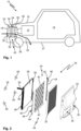
- FIG. 1 shows a vehicle 10, here a passenger car.
- the vehicle is powered by an engine 12, in this case a combustion engine. Passengers and luggage may be accommodated inside a cabin 14.
- a body 16 of the vehicle 10 comprises a front skirt 18.
- the vehicle 10 comprises a filter cooler system 20.
- the filter cooler system 20 is arranged behind the front skirt 18 and in front of the engine 12 at a front end of the vehicle 10.
- the filter cooler system 20 comprises an air duct 22, a filter assembly 24 and a cooler assembly 26.
- the filter assembly 24 is arranged behind the air duct 22 and in front of the cooler assembly 26.
- the air duct 22, the filter assembly 24, and the cooler assembly 26 are collectively mounted to several, here four, common mounting tabs 28, two of which are visible in Figure 1 .
- the mounting tabs 28 are fixed to the body 16, as indicated by hatchings.
- Air passes through not depicted openings in the front skirt 18 and enters the air duct 22 at an inlet opening 30.
- the air is guided to the filter assembly 24 in the air duct 22.
- a filter element 32 of the filter assembly 24 captures particles, in particular fine dust, from air flow 33.
- the filter element is a fine dust filter element.
- the filter element 32 can be made from pleated filter paper.
- the filter element 32 is attached to a holder 34 of the filter assembly 24, which holder 34 provides fixation of the filter assembly 24 to the mounting tabs 28.
- the air After having passed the cooler assembly 26, the air is released into the environment of the vehicle 10, for instance through an underside 37 of the vehicle 10.
- the air, which is guided through the filter cooler assembly 26 is in particular neither introduced into the engine 12 nor into the cabin 14.
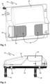
- Figure 2 shows an embodiment of a filter cooler system 20 in an exploded view.
- Four mounting tabs 28 have a basically rectangular cross section and extend along a longitudinal axis.
- a cooler assembly 26 has four mounting eyes 38, each configured to engage around one of the mounting tabs 28, cf. Figure 3 .
- the mounting eyes 38 are completely closed in circumferential direction.
- a filter assembly 24 of system 20 comprises a holder 34 and a plate shaped filter element 32.
- the holder 34 comprises a grid frame 40, to which the filter element 32 is affixed, e.g., glued or welded.
- a support leg 42 protrudes from a lower side of grid frame 40. The support leg 42 ensures vertical support and vertical alignment of filter element 32.
- the holder 34 further comprises two mounting rails 44. Each mounting rail 44 has a slot 45 for receiving the grid frame 40.
- the holder 34 has four mounting brackets 46 for fixation to the mounting tabs 28, cf. also Figure 4 . Here, two mounting brackets 46 are provided at each of the mounting rails 44.
- a front surface 47 of the mounting tabs 28 serves for axial abutment of the mounting brackets 46 of holder 34.
- Four claws 48 which protrude from each of the mounting brackets 46, engage the mounting tab 28 on its four side faces 50.
- the holder 34 further has two latching hooks 52, one of which is provided at each mounting rail 44, cf. in particular Figure 2 .
- the latching hooks 52 engage the cooler assembly 26 in a snap fit, to prevent the filter assembly 24 from disengaging form the mounting tabs 28 prior to fixation of air duct 22.
- the air duct 22, which in this embodiment has two inlet openings 30, is mounted to the mounting tabs 28 in front of the filter assembly 24, cf. Figures 5 and 6 .
- a screw 54 is used to fix the air duct 22 and the filter assembly 24 to the respective mounting tab 28, cf. Figure 7 .
- the screw 54 penetrates through the air duct 22 and through an opening 56 of the mounting bracket 46 of the holder 34. No threaded engagement of the screw 54 with the air duct 22 and the holder 34 is provided.
- the screw 54 engages internal threads (not shown) of a screw hole 58 of the mounting tab 28, the screw hole 59 extending along the mounting tab 28 perpendicular to its front surface 47.
- the holder 34 particularly its mounting brackets 46, is held clamped between a mounting surface 60 of the air duct 22 and the front surface 47 of the mounting tab 28.
- angular claws 62 protruding from the air duct 22 near its mounting surface 60 may engage edges between the side faces 50 of the mounting tab 28.
- FIGS 9 , 10 and 11 show an embodiment of filter cooler system 20', which in many aspects corresponds to the filter cooler system 20 depicted in Figures 2 to 8 . Mainly the differences will be described below. For common features, reference is made to the description above and Figures 2 to 8 .
- a mounting bracket 46' of holder 34 is designed to partially cover a front surface 47 of a mounting tab 28, cf. Figure 9 .
- a mounting surface 60' of air duct 22 is designed to abut the remainder of the front surface 47, cf. Figure 10 .
- two claws 48' which are integrally formed with one another, protrude from mounting bracket 46 and engage two adjacent side faces 50 of the mounting tab 28, cf. Figure 11 .
- the claws 48' of holder 34 are received in a circumferentially open section of the annular claw 64 of the air duct 22.
- the holder 34 is provided with centering holes 66, which may be arranged at the mounting brackets, cf. Figure 9 .
- Centering pins 68 of the air duct 22 are received in the centering holes 66, when the air duct 22 is being attached.
- the centering pins 68 may be integrally formed with the air duct 22.
- the invention relates to a filter cooler system comprising a cooler assembly, a filter assembly and an air duct. These components are jointly mounted to at least one mounting tab.
- the filter assembly is held clamped between the mounting tab and the air duct.
- a mounting eye of the cooler assembly may engage around the mounting tab.
- a snap fit between the filter assembly and the cooler assembly may be provided.
Landscapes
- Engineering & Computer Science (AREA)
- Chemical & Material Sciences (AREA)
- Combustion & Propulsion (AREA)
- Mechanical Engineering (AREA)
- General Engineering & Computer Science (AREA)
- Transportation (AREA)
- Cooling, Air Intake And Gas Exhaust, And Fuel Tank Arrangements In Propulsion Units (AREA)
Abstract
Description
- The present invention refers to a filter cooler system for a motor vehicle, comprising
a cooler assembly; an air duct having at least one inlet opening; and a filter assembly with a filter element. - Such a filter cooler system is known form
WO 2019/110223 A1 . -
WO 2019/110223 A1 discloses a motor vehicle, which has at least one air inlet opening in a front region, behind which an ambient air cleaning device is arranged, which is designed, for the removal of particles, in particular fine dust and/or gases from the ambient air. The ambient air cleaning device has at least one filter element with at least one filter medium that is folded to form at least one filter bellows, wherein the filter element has a plurality of fold stabilising means which support the filter bellows and are provided at a lateral distance of no more than 130 mm from one another. - Filter cooler systems of this kind can be used to filter ambient air in order to decrease the total dust emission balance of a vehicle. To this end, the filter element may remove dust particles from the ambient air in order to compensate, preferably overcompensate, the dust production during use of the vehicle.
- Depending on the intended area of use or with regard to production cost, it may be sufficient to equip some but not all vehicles of a certain type with a filter element for ambient air filtration. Furthermore, the optional mounting of an air filter element shall not alter insurance classification of the vehicle.
- It is an object of the invention to facilitate mounting of an air filter assembly to a cooler assembly for a vehicle.
- This is achieved by a filter cooler system according to claim 1, a filter assembly according to
claim 12 and a motor vehicle according to claim 13. Advantageous embodiments are given in the subclaims and the description. - In accordance with the invention, a filter cooler system for a motor vehicle is provided. The filter cooler system comprises a cooler assembly, an air duct having at least one inlet opening, and a filter assembly.
- The cooler assembly may comprise a liquid cooler and a fan. Cooling liquid for an engine of the vehicle may be fed through the liquid cooler.
- The filter assembly comprises a filter element and a holder. Preferably, the filter element is permanently affixed to the holder. For instance, the filter element may be glued to the holder. The filter element is preferably a flat filter element. With a flat filter element, the risk of damage to the cooler system during an accident is reduced. A thickness of the filter element may be less than 5 cm, preferably less than 3 cm. The filter element may be pleated.
- The air duct is generally arranged in front of the cooler assembly. The air duct is typically designed for arrangement behind a front skirt of the vehicle or for being part of the front skirt.
- According to the invention, the filter element is arranged between the air duct and the cooler assembly. Consequently, air entering a front end of the vehicle is guided through the inlet opening first to the filter element and then to the cooler assembly. Furthermore, the filter element protects the cooler assembly from being hit by stones or the like. The air duct may be sealed against the filter element using foam.
- Further according to the invention, the cooler assembly, the filter assembly, and the air duct are fixed to at least one common mounting tab. This facilitates mounting of the filter cooler system. A mounting sequence for the filter cooler system is typically arranging the cooler assembly at the mounting tab, arranging the filter assembly at the mounting tab, arranging the air duct at the mounting tab, fixing the air duct to the mounting tab.
- By fixing the air duct to the mounting tab, also the filter assembly and preferably the cooler assembly are fixedly secured at the mounting tab. In particular, the filter assembly is fixed to the mounting tab via the holder. In other words, the holder is fixed to the mounting tab, thereby securing the filter element relative to the mounting tab, and consequently relative to the air duct and the cooler assembly.
- if at all, only a slight modification of the air duct is required for use with or without the filter assembly. In particular, slightly shifting the position of a mounting surface of the air duct forward or backward a few millimeters may suffice to adapt the air duct for use with or without a filter assembly.
- The mounting tab may also be referred to as a mounting stud. Typically, the mounting tab or stud extends along a longitudinal axis, preferably with a rectangular cross section. A front surface of the mounting tab is preferably arranged perpendicular to the longitudinal axis.
- The mounting tab is typically permanently fixed to the body. Preferably, four mounting tabs are provided. With four mounting tabs at the corners of the filter assembly, of the cooler assembly and of the air duct a particularly solid mounting of the aforementioned components can be achieved.
- Preferably, the holder is clamped (in other words compressed) between the air duct and the mounting tab. This contributes to securely fixing the filter assembly to the mounting tab.
- Preferably, the cooler assembly, the filter assembly and the air duct are screwed to the at least one common mounting tab. A screw penetrates at least through the air duct and into a screw hole of the mounting tab. A particular secure and tight fixation can be obtained using at least one screw. Further, screws are easy to install and allow for automatic adaption of the fixation to the presence or absence of the filter assembly. The screw hole in the mounting tab is typically provided with an internal thread for engagement of an external thread of the screw.
- In an advantageous embodiment, the screw penetrates through the holder of the filter assembly. Consequently, even if the screw is not completely tightened, the holder cannot disengage from the mounting tab. Typically, an opening of the holder, through which the screw passes, is free of threads.
- Alternatively, the screw may pass besides the holder into the mounting tab. In this embodiment, an engagement section of the holder may complement a mounting surface of the air duct in order to completely covering a front surface of the mounting tab. Both, the mounting section of the holder and the mounting surface of the air duct are preferably pressed against the front surface of the mounting tab by tightening the screw.
- A mounting eye of the cooler assembly may engage around the mounting tab. This ensures that the cooler assembly rests in place while mounting the other components of the system. Preferably, the mounting eye is completely closed in circumferential direction. The mounting eye may surround the mounting tab.
- In an advantageous embodiment, the holder of the filter assembly comprises a plurality claws for engagement on different sides of the mounting tab. The claws position the filter assembly transverse to a longitudinal direction of the mounting tab. In particular during assembly of the system, i. e. prior to fixation of the air duct, the claws may hold the filter assembly to the mounting tab in a substantially vertical plane.
- It may be provided, that two claws engage on two adjacent side faces of the mounting tab. Thereby, the filter assembly is positioned in two different directions relative to the mounting tab. The two claws may be orthogonal to one another.
- Additionally or alternatively, two claws may engage on two opposing side faces of the mounting tab. In particular, two pairs of claws may engage on two pairs of opposing side faces. Opposing claws ensure precise alignment of the filter assembly relative to the mounting tab.
- The holder may comprise two mounting rails and a grid frame. The grid frame stabilizes the filter element. The filter element may be glued to the grid frame. Preferably, a support leg protrudes from the grid frame. The support leg may engage a lower side of the filter element.
- The mounting rails each may have a slot for engagement of the grid frame. The slots facilitate mounting of the filter assembly.
- Preferably, the holder has at least one latching hook for engagement on the cooler assembly. This prevents the filter assembly from disengaging from the mounting tab during assembly of the system.
- The holder may have a centering hole into which a centering pin of the air duct engages. This contributes to ensure alignment of the air duct relative to the filter assembly, and thereby relative to the mounting tab on which the filter assembly is (pre-) mounted, in particular prior to insertion of a screw.
- The filter element may be a fine dust filter element, preferably according to class ISO ePM2,5 70%, particularly preferably according to class ISO ePM1 70%, of EN ISO 16890.
- The invention also relates to a filter assembly for a filter cooler system according to the invention. The filter assembly comprises a filter element and a holder. The holder is designed to be fixed to a mounting tab. In particular, the holder is designed to be clamped between an air duct and the mounting tab. The filter assembly may comprise further features as described above. The filter element may be glued to the holder. The filter element is preferably a flat filter element. The holder may have an opening free of threads, through which a screw may be led to fix the holder to the mounting tab. The holder may comprise a plurality of claws extending perpendicular to an extension plane of the flat filter element. The holder may comprise two mounting rails and a grid frame. The mounting rails each may have a slot for engagement of the grid frame. The holder may have a centering hole for engagement of a centering pin of the air duct.
- The invention further relates to a motor vehicle, in particular a passenger car, van or truck, comprising a filter cooler system according to the invention, as described above.
- Preferably, the at least one mounting tab is fixed to a body of the vehicle. This allows securely positioning the filter assembly as required, in particular at a front end of the vehicle.
- The filter cooler system may be arranged at a front end of the vehicle, in particular behind a front skirt and/or in front of an engine, in particular a combustion engine or an electric engine. In this position, the efficiency of both the filter element and the cooler are increased. With a combustion engine, reduction of ambient air pollution may be required to fulfill legal requirements.
- Other advantages and features of the invention will be appreciated from the following description of embodiments of the invention with reference to the figures of the drawing, which show significant details, and from the claims. The individual features, as described above or explained below, may each be implemented individually or implemented together in any useful combination in variants of the invention.
-
Fig. 1 shows a vehicle according to the invention having a filter cooler system according to the invention in a schematic sketch. -
Fig. 2 shows a first embodiment of a filter cooler system according to the invention, in a schematic exploded view. -
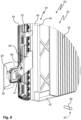
Fig. 3 shows a mounting eye of a cooler assembly of the filter cooler system ofFig. 2 engaging around a mounting tab, in a schematic perspective view. -
Fig. 4 shows a holder of a filter assembly of the filter cooler system ofFig. 2 arranged on the mounting tab, in a schematic perspective view. -
Fig. 5 shows a schematic front view of the filter cooler system ofFig. 2 in an assembled state with an air duct attached to the mounting tabs. -
Fig. 6 shows a schematic side view of the filter cooler system ofFig. 2 in an assembled state. -
Fig. 7 shows a schematic longitudinal section through a mounting tab of the filter cooler system ofFig. 2 with the holder and the air duct being fixed to the mounting tab by a screw. -
Fig. 8 shows a schematic cross section through a mounting tab of the filter cooler system ofFig. 2 with angular claws of the air duct engaging edges of the mounting tab. -
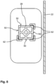
Fig. 9 shows a similar view asFig. 4 for a second embodiment of a filter cooler system according to the invention, with a mounting eye of a cooler assembly engaging around a mounting tab and a holder of a filter assembly arranged on the mounting tab. -
Fig. 10 shows a schematic longitudinal section through the mounting tab of the filter cooler system ofFig. 9 , with the holder and the air duct being pressed against a front surface of the mounting tab besides each other by a screw. -
Fig. 11 shows a schematic cross section through the mounting tab of the filter cooler system ofFig. 9 with claws of the holder engaging on adjacent side faces of the mounting tab. -
Figure 1 shows avehicle 10, here a passenger car. The vehicle is powered by anengine 12, in this case a combustion engine. Passengers and luggage may be accommodated inside acabin 14. Abody 16 of thevehicle 10 comprises afront skirt 18. - The
vehicle 10 comprises a filtercooler system 20. The filtercooler system 20 is arranged behind thefront skirt 18 and in front of theengine 12 at a front end of thevehicle 10. - The filter
cooler system 20 comprises anair duct 22, afilter assembly 24 and acooler assembly 26. Thefilter assembly 24 is arranged behind theair duct 22 and in front of thecooler assembly 26. Theair duct 22, thefilter assembly 24, and thecooler assembly 26 are collectively mounted to several, here four, common mountingtabs 28, two of which are visible inFigure 1 . The mountingtabs 28 are fixed to thebody 16, as indicated by hatchings. - Air passes through not depicted openings in the
front skirt 18 and enters theair duct 22 at aninlet opening 30. The air is guided to thefilter assembly 24 in theair duct 22. Afilter element 32 of thefilter assembly 24 captures particles, in particular fine dust, fromair flow 33. Here, the filter element is a fine dust filter element. Thefilter element 32 can be made from pleated filter paper. Thefilter element 32 is attached to aholder 34 of thefilter assembly 24, whichholder 34 provides fixation of thefilter assembly 24 to the mountingtabs 28. - After passing through the
filter element 32, the air strikes thecooler assembly 26. Thereby, cooling is provided to a cooling fluid for theengine 12, cf.fluid lines 36. - After having passed the
cooler assembly 26, the air is released into the environment of thevehicle 10, for instance through anunderside 37 of thevehicle 10. The air, which is guided through the filtercooler assembly 26 is in particular neither introduced into theengine 12 nor into thecabin 14. -
Figure 2 shows an embodiment of a filtercooler system 20 in an exploded view. - Four mounting
tabs 28 have a basically rectangular cross section and extend along a longitudinal axis. - A
cooler assembly 26 has four mountingeyes 38, each configured to engage around one of the mountingtabs 28, cf.Figure 3 . Here, the mountingeyes 38 are completely closed in circumferential direction. - A
filter assembly 24 ofsystem 20 comprises aholder 34 and a plate shapedfilter element 32. Theholder 34 comprises agrid frame 40, to which thefilter element 32 is affixed, e.g., glued or welded. Asupport leg 42 protrudes from a lower side ofgrid frame 40. Thesupport leg 42 ensures vertical support and vertical alignment offilter element 32. - The
holder 34 further comprises two mountingrails 44. Each mountingrail 44 has aslot 45 for receiving thegrid frame 40. Theholder 34 has four mountingbrackets 46 for fixation to the mountingtabs 28, cf. alsoFigure 4 . Here, two mountingbrackets 46 are provided at each of the mounting rails 44. - A
front surface 47 of the mountingtabs 28 serves for axial abutment of the mountingbrackets 46 ofholder 34. Fourclaws 48, which protrude from each of the mountingbrackets 46, engage the mountingtab 28 on its four side faces 50. - The
holder 34 further has two latchinghooks 52, one of which is provided at each mountingrail 44, cf. in particularFigure 2 . During assembly ofsystem 20, the latching hooks 52 engage thecooler assembly 26 in a snap fit, to prevent thefilter assembly 24 from disengaging form the mountingtabs 28 prior to fixation ofair duct 22. - Finally, the
air duct 22, which in this embodiment has twoinlet openings 30, is mounted to the mountingtabs 28 in front of thefilter assembly 24, cf.Figures 5 and 6 . At each mountingtab 28, ascrew 54 is used to fix theair duct 22 and thefilter assembly 24 to the respective mountingtab 28, cf.Figure 7 . In this embodiment, thescrew 54 penetrates through theair duct 22 and through anopening 56 of the mountingbracket 46 of theholder 34. No threaded engagement of thescrew 54 with theair duct 22 and theholder 34 is provided. Thescrew 54 engages internal threads (not shown) of ascrew hole 58 of the mountingtab 28, the screw hole 59 extending along the mountingtab 28 perpendicular to itsfront surface 47. Thereby, theholder 34, particularly its mountingbrackets 46, is held clamped between a mountingsurface 60 of theair duct 22 and thefront surface 47 of the mountingtab 28. - As can be seen in
Figure 8 ,angular claws 62 protruding from theair duct 22 near its mounting surface 60 (seeFigure 7 ) may engage edges between the side faces 50 of the mountingtab 28. -
Figures 9 ,10 and 11 show an embodiment of filter cooler system 20', which in many aspects corresponds to the filtercooler system 20 depicted inFigures 2 to 8 . Mainly the differences will be described below. For common features, reference is made to the description above andFigures 2 to 8 . - A mounting bracket 46' of
holder 34 is designed to partially cover afront surface 47 of a mountingtab 28, cf.Figure 9 . A mounting surface 60' ofair duct 22 is designed to abut the remainder of thefront surface 47, cf.Figure 10 . By tightening ascrew 54, both theair duct 22 and the mounting bracket 46' ofholder 34 are pressed against the mountingtab 28. In particular, the mounting bracket 46' of theholder 34 is clamped between theair duct 22 and the mountingtab 28. Thescrew 54 penetrates through theair duct 22 and passes besides the mounting bracket 46'. - In this embodiment of system 20', two claws 48', which are integrally formed with one another, protrude from mounting
bracket 46 and engage two adjacent side faces 50 of the mountingtab 28, cf.Figure 11 . Anannular claw 64 of theair duct 22, whichannular claw 64 is partially closed in circumferential direction, engages all four side faces 50 of the mountingtab 28. The claws 48' ofholder 34 are received in a circumferentially open section of theannular claw 64 of theair duct 22. - In this embodiment of system 20', the
holder 34 is provided with centeringholes 66, which may be arranged at the mounting brackets, cf.Figure 9 . Centering pins 68 of theair duct 22 are received in the centeringholes 66, when theair duct 22 is being attached. The centering pins 68 may be integrally formed with theair duct 22. - In summary, the invention relates to a filter cooler system comprising a cooler assembly, a filter assembly and an air duct. These components are jointly mounted to at least one mounting tab. Preferably, the filter assembly is held clamped between the mounting tab and the air duct. A mounting eye of the cooler assembly may engage around the mounting tab. A snap fit between the filter assembly and the cooler assembly may be provided.
-
-
Vehicle 10 -
Engine 12 -
Cabin 14 -
Body 16 -
Front skirt 18 -
Filter cooler system 20; 20' -
Air duct 22 -
Filter assembly 24 -
Cooler assembly 26 - Mounting
tab 28 -
Inlet opening 30 -
Filter element 32 -
Air flow 33 -
Holder 34 -
Fluid line 36 -
Underside 37 - Mounting
eye 38 -
Grid frame 40 -
Support leg 42 - Mounting
rail 44 -
Slot 45 - Mounting
bracket 46; 46' -
Front surface 47 -
Claw 48; 48' -
Side face 50 - Latching
hook 52 -
Screw 54 -
Opening 56 -
Screw hole 58 - Mounting
surface 60; 60' -
Angular claw 62 -
Annular claw 64 - Centering
hole 66 - Centering
pin 68
Claims (14)
- A filter cooler system (20, 20') for a motor vehicle (10), the filter cooler system (20, 20') comprising:a cooler assembly (26);an air duct (22) having at least one inlet opening (30); anda filter assembly (24) comprising a filter element (32) and a holder (34), the filter element (32) being arranged between the air duct (22) and the cooler assembly (26),wherein the cooler assembly (26), the holder (34) and the air duct (22) are fixed to at least one common mounting tab (28), andwherein the holder (34) is clamped between the air duct (22) and the at least one mounting tab (28).
- The filter cooler system (20, 20') according to claim 1, wherein the cooler assembly (26), the filter assembly (24) and the air duct (22) are screwed to the at least one common mounting tab (28) by a screw (54) penetrating at least through the air duct (22) and into a screw hole (58) of the at least one mounting tab (28).
- The filter cooler system (20) according to claim 2, wherein the screw (54) further penetrates through the holder (34) of the filter assembly (24).
- The filter cooler system (20, 20') according to one of the preceding claims, wherein the cooler assembly (26) comprises a mounting eye (38) for engagement around the at least one mounting tab (28).
- The filter cooler system (20, 20') according to one of the preceding claims, wherein the holder (34) of the filter assembly (24) comprises a plurality of claws (48, 48') for engagement on different sides of the at least one mounting tab (28).
- The filter cooler system (20, 20') according to claim 5, wherein the plurality of claws (48, 48') comprises two claws (48, 48') for engagement on two adjacent side faces (50) of the at least one mounting tab (28).
- The filter cooler system (20) according to claim 5 or 6, wherein the plurality of claws (48, 48') comprises two pairs of claws (48) for engagement on two pairs of opposing side faces (50) of the at least one mounting tab (28).
- The filter cooler system (20, 20') according to one of the preceding claims, wherein the holder (34) comprises two mounting rails (44), a grid frame (40), and a support leg (42) protruding from the grid frame (40).
- The filter cooler system (20, 20') according to one of the preceding claims, wherein the holder (34) has at least one latching hook (52) for engagement on the cooler assembly (26).
- The filter cooler system (20') according to one of the preceding claims, wherein the holder (34) has a centering hole (66) into which a centering pin (68) of the air duct (22) engages.
- A filter assembly (24) for the filter cooler system (20, 20') according to one of claims 1 to 10.
- A motor vehicle (10) comprising the filter cooler system (20, 20') according to one of claims 1 to 10.
- The motor vehicle (10) according to claim 12, further comprising a body (16) to which the at least one mounting tab (28) is fixed.
- The motor vehicle (10) according to claim 12 or 13, further comprising an engine (12) and a front skirt (18),
wherein the filter cooler system (20, 20') is arranged at a front end of the motor vehicle (10), behind the front skirt (18) and in front of the engine (12).
Priority Applications (2)
| Application Number | Priority Date | Filing Date | Title |
|---|---|---|---|
| EP23178570.0A EP4477852A1 (en) | 2023-06-12 | 2023-06-12 | Filter cooler system for a motor vehicle |
| PCT/EP2024/057897 WO2024256051A1 (en) | 2023-06-12 | 2024-03-25 | Filter cooler system for motor vehicle |
Applications Claiming Priority (1)
| Application Number | Priority Date | Filing Date | Title |
|---|---|---|---|
| EP23178570.0A EP4477852A1 (en) | 2023-06-12 | 2023-06-12 | Filter cooler system for a motor vehicle |
Publications (1)
| Publication Number | Publication Date |
|---|---|
| EP4477852A1 true EP4477852A1 (en) | 2024-12-18 |
Family
ID=86760651
Family Applications (1)
| Application Number | Title | Priority Date | Filing Date |
|---|---|---|---|
| EP23178570.0A Pending EP4477852A1 (en) | 2023-06-12 | 2023-06-12 | Filter cooler system for a motor vehicle |
Country Status (2)
| Country | Link |
|---|---|
| EP (1) | EP4477852A1 (en) |
| WO (1) | WO2024256051A1 (en) |
Citations (4)
| Publication number | Priority date | Publication date | Assignee | Title |
|---|---|---|---|---|
| DE202006004522U1 (en) * | 2006-03-22 | 2006-06-08 | Blue Corporate Finance Gmbh & Co. Kg | Fine dust filter system for vehicle is fitted in main air flow between grille serving as air inlet, and radiator |
| DE102012009950A1 (en) * | 2012-05-18 | 2013-11-21 | Brose Fahrzeugteile GmbH & Co. Kommanditgesellschaft, Würzburg | Cooling fan module for motor car, has cooler and radiator trim whose edge portions are connected by the retaining element arranged between the tabs, for influencing the resonant frequency of the radiator trim |
| WO2015171183A1 (en) * | 2014-05-07 | 2015-11-12 | Abell Ned | Method and device for removing airborne pollutants |
| WO2019110223A1 (en) | 2017-12-08 | 2019-06-13 | Mann+Hummel Gmbh | Motor vehicle having an ambient air filtration device and ambient air filtration device |
-
2023
- 2023-06-12 EP EP23178570.0A patent/EP4477852A1/en active Pending
-
2024
- 2024-03-25 WO PCT/EP2024/057897 patent/WO2024256051A1/en not_active Ceased
Patent Citations (4)
| Publication number | Priority date | Publication date | Assignee | Title |
|---|---|---|---|---|
| DE202006004522U1 (en) * | 2006-03-22 | 2006-06-08 | Blue Corporate Finance Gmbh & Co. Kg | Fine dust filter system for vehicle is fitted in main air flow between grille serving as air inlet, and radiator |
| DE102012009950A1 (en) * | 2012-05-18 | 2013-11-21 | Brose Fahrzeugteile GmbH & Co. Kommanditgesellschaft, Würzburg | Cooling fan module for motor car, has cooler and radiator trim whose edge portions are connected by the retaining element arranged between the tabs, for influencing the resonant frequency of the radiator trim |
| WO2015171183A1 (en) * | 2014-05-07 | 2015-11-12 | Abell Ned | Method and device for removing airborne pollutants |
| WO2019110223A1 (en) | 2017-12-08 | 2019-06-13 | Mann+Hummel Gmbh | Motor vehicle having an ambient air filtration device and ambient air filtration device |
Also Published As
| Publication number | Publication date |
|---|---|
| WO2024256051A1 (en) | 2024-12-19 |
Similar Documents
| Publication | Publication Date | Title |
|---|---|---|
| US8236079B2 (en) | Air filter system for a vehicle and method for mounting the same | |
| CN110192020B (en) | Motor vehicle, air filter housing assembly and method of directing air to an air intake | |
| US7699338B2 (en) | Removable airbag hook bracket for serviceability | |
| JP6293906B2 (en) | Automotive battery pack | |
| US5996684A (en) | Radiator and condenser assembly | |
| US20010054497A1 (en) | Cooling unit for use with a cooling system of internal combustion engines | |
| US10605210B2 (en) | Filter arrangement | |
| CN101610928A (en) | Battery fixing structure for electric vehicles | |
| KR20200134366A (en) | Ohc bracket mounted on headliner for vehicle | |
| CN103770630A (en) | Mounting part for body attachment parts in the automotive field, and a mounting arrangement having a mounting part of said type | |
| EP4477852A1 (en) | Filter cooler system for a motor vehicle | |
| CA2658430C (en) | Independently adjustable chassis skirt mounting assembly | |
| CN112428948A (en) | Connecting device for connecting a vehicle impact-absorbing member to a vehicle body part | |
| ES2740726T3 (en) | Assembly comprising a separation panel and a deflector | |
| US20030122354A1 (en) | Roof rail air bag assembly and method of installation | |
| CN101456432A (en) | Guide structure for installing driver's cab module in vehicle | |
| US20240218848A1 (en) | Air filter assembly for cleaning an air stream for a commercial vehicle | |
| US20050039024A1 (en) | System and method for engine compartment optimization | |
| CN102795168A (en) | Installation conversion support assembly and vehicle | |
| CN101234591A (en) | Vehicle-mounted air purifying device | |
| US7563007B2 (en) | Bumper cover and lamp housing assembly with integral fasteners for independent removal of parts from a vehicle | |
| US20260048653A1 (en) | Modular hood plenum | |
| JP4605503B2 (en) | Vehicle fresh air duct mounting structure | |
| US10220805B2 (en) | Radiator grille attachment | |
| US20080083480A1 (en) | Fixing Device and Method for Producing the Same |
Legal Events
| Date | Code | Title | Description |
|---|---|---|---|
| PUAI | Public reference made under article 153(3) epc to a published international application that has entered the european phase |
Free format text: ORIGINAL CODE: 0009012 |
|
| STAA | Information on the status of an ep patent application or granted ep patent |
Free format text: STATUS: THE APPLICATION HAS BEEN PUBLISHED |
|
| AK | Designated contracting states |
Kind code of ref document: A1 Designated state(s): AL AT BE BG CH CY CZ DE DK EE ES FI FR GB GR HR HU IE IS IT LI LT LU LV MC ME MK MT NL NO PL PT RO RS SE SI SK SM TR |
|
| STAA | Information on the status of an ep patent application or granted ep patent |
Free format text: STATUS: REQUEST FOR EXAMINATION WAS MADE |
|
| 17P | Request for examination filed |
Effective date: 20250618 |
|
| STAA | Information on the status of an ep patent application or granted ep patent |
Free format text: STATUS: EXAMINATION IS IN PROGRESS |
|
| 17Q | First examination report despatched |
Effective date: 20251126 |