EP4477780A1 - Layer system for an electrolyser - Google Patents
Layer system for an electrolyser Download PDFInfo
- Publication number
- EP4477780A1 EP4477780A1 EP23178698.9A EP23178698A EP4477780A1 EP 4477780 A1 EP4477780 A1 EP 4477780A1 EP 23178698 A EP23178698 A EP 23178698A EP 4477780 A1 EP4477780 A1 EP 4477780A1
- Authority
- EP
- European Patent Office
- Prior art keywords
- layer
- bipolar
- perforated
- layers
- layer system
- Prior art date
- Legal status (The legal status is an assumption and is not a legal conclusion. Google has not performed a legal analysis and makes no representation as to the accuracy of the status listed.)
- Withdrawn
Links
Images

Classifications
-
- C—CHEMISTRY; METALLURGY
- C25—ELECTROLYTIC OR ELECTROPHORETIC PROCESSES; APPARATUS THEREFOR
- C25B—ELECTROLYTIC OR ELECTROPHORETIC PROCESSES FOR THE PRODUCTION OF COMPOUNDS OR NON-METALS; APPARATUS THEREFOR
- C25B13/00—Diaphragms; Spacing elements
- C25B13/02—Diaphragms; Spacing elements characterised by shape or form
-
- C—CHEMISTRY; METALLURGY
- C25—ELECTROLYTIC OR ELECTROPHORETIC PROCESSES; APPARATUS THEREFOR
- C25B—ELECTROLYTIC OR ELECTROPHORETIC PROCESSES FOR THE PRODUCTION OF COMPOUNDS OR NON-METALS; APPARATUS THEREFOR
- C25B1/00—Electrolytic production of inorganic compounds or non-metals
- C25B1/01—Products
- C25B1/02—Hydrogen or oxygen
- C25B1/04—Hydrogen or oxygen by electrolysis of water
-
- C—CHEMISTRY; METALLURGY
- C25—ELECTROLYTIC OR ELECTROPHORETIC PROCESSES; APPARATUS THEREFOR
- C25B—ELECTROLYTIC OR ELECTROPHORETIC PROCESSES FOR THE PRODUCTION OF COMPOUNDS OR NON-METALS; APPARATUS THEREFOR
- C25B11/00—Electrodes; Manufacture thereof not otherwise provided for
- C25B11/02—Electrodes; Manufacture thereof not otherwise provided for characterised by shape or form
- C25B11/03—Electrodes; Manufacture thereof not otherwise provided for characterised by shape or form perforated or foraminous
-
- C—CHEMISTRY; METALLURGY
- C25—ELECTROLYTIC OR ELECTROPHORETIC PROCESSES; APPARATUS THEREFOR
- C25B—ELECTROLYTIC OR ELECTROPHORETIC PROCESSES FOR THE PRODUCTION OF COMPOUNDS OR NON-METALS; APPARATUS THEREFOR
- C25B11/00—Electrodes; Manufacture thereof not otherwise provided for
- C25B11/02—Electrodes; Manufacture thereof not otherwise provided for characterised by shape or form
- C25B11/036—Bipolar electrodes
-
- C—CHEMISTRY; METALLURGY
- C25—ELECTROLYTIC OR ELECTROPHORETIC PROCESSES; APPARATUS THEREFOR
- C25B—ELECTROLYTIC OR ELECTROPHORETIC PROCESSES FOR THE PRODUCTION OF COMPOUNDS OR NON-METALS; APPARATUS THEREFOR
- C25B9/00—Cells or assemblies of cells; Constructional parts of cells; Assemblies of constructional parts, e.g. electrode-diaphragm assemblies; Process-related cell features
- C25B9/17—Cells comprising dimensionally-stable non-movable electrodes; Assemblies of constructional parts thereof
- C25B9/19—Cells comprising dimensionally-stable non-movable electrodes; Assemblies of constructional parts thereof with diaphragms
-
- C—CHEMISTRY; METALLURGY
- C25—ELECTROLYTIC OR ELECTROPHORETIC PROCESSES; APPARATUS THEREFOR
- C25B—ELECTROLYTIC OR ELECTROPHORETIC PROCESSES FOR THE PRODUCTION OF COMPOUNDS OR NON-METALS; APPARATUS THEREFOR
- C25B9/00—Cells or assemblies of cells; Constructional parts of cells; Assemblies of constructional parts, e.g. electrode-diaphragm assemblies; Process-related cell features
- C25B9/70—Assemblies comprising two or more cells
- C25B9/73—Assemblies comprising two or more cells of the filter-press type
- C25B9/75—Assemblies comprising two or more cells of the filter-press type having bipolar electrodes
-
- C—CHEMISTRY; METALLURGY
- C25—ELECTROLYTIC OR ELECTROPHORETIC PROCESSES; APPARATUS THEREFOR
- C25B—ELECTROLYTIC OR ELECTROPHORETIC PROCESSES FOR THE PRODUCTION OF COMPOUNDS OR NON-METALS; APPARATUS THEREFOR
- C25B9/00—Cells or assemblies of cells; Constructional parts of cells; Assemblies of constructional parts, e.g. electrode-diaphragm assemblies; Process-related cell features
- C25B9/70—Assemblies comprising two or more cells
- C25B9/73—Assemblies comprising two or more cells of the filter-press type
- C25B9/77—Assemblies comprising two or more cells of the filter-press type having diaphragms
Definitions
- the present disclosure relates to a layer system for an electrolyser and a respective electrolyser.
- Electrolysers are devices that are used to split water into its constituent parts, namely hydrogen and oxygen, through the process of electrolysis. This technology has been widely studied and implemented for a range of applications, including the production of hydrogen as a fuel, the generation of oxygen for medical and industrial purposes, and the removal of impurities from water.
- Electrolysers can use renewable energy sources, such as wind and solar, to produce hydrogen, which can then be used as a clean and versatile energy carrier. Moreover, electrolysers can be used to store excess energy, allowing for the integration of intermittent renewable sources into the grid.
- the layer system of an electrolyser primarily determines how easily the electrolyser can be manufactured, assembled, and/or maintained. Moreover, the layer system is crucial for the efficiency and durability of the electrolyser.
- the present invention aims to provide a simpler layer system for an electrolyser, particularly an alkaline electrolyser.
- the object is achieved by a layer system for an electrolyser, wherein the layer system comprises a base layer stack having the following layers in the given order: (i) a first perforated layer with a plurality of perforations; (ii) a first bipolar layer, and (iii) a second perforated layer with a plurality of perforations.
- the first bipolar layer comprises first distancing means on a first surface to space the first perforated layer apart from the first bipolar layer.
- the first bipolar layer comprises second distancing means on a second surface being opposite to the first surface to space the second perforated layer apart from the first bipolar layer.
- the first perforated layer may be configured as a cathode and/or an anode. Further, the second perforated layer may also be configured as a cathode and/or an anode. It is understood that when the first perforated layer is configured as an anode, then the second perforated layer is configured as a cathode, and vice versa.
- the first perforated layer and/or the second perforated layer may have a thickness which lies in a range from 0.3 mm to 1.5 mm, preferably from 0.5 to 1 mm, and further preferably from 0.7 mm to 0.8 mm. It has shown that these thicknesses provide for sufficient stability while excess material is avoided.
- the perforations of the first perforated layer and/or the second perforated layer may comprise round through holes, rectangular through holes, and/or through holes of any other shape. Further, the perforations of the first perforated layer and/or the second perforated layer may be arranged in regular patterns.
- the first surface and/or the second surface of the first bipolar layer may be defined as the surfaces of the first bipolar layer which are adjacent to the respective distancing means.
- the first bipolar layer is a sheet metal and the first distancing means are spherical elements embossed into this sheet metal, then the first surface may be defined as the undeformed surface being adjacent to the embossed spherical element and facing the first perforated layer.
- the layer system according to the present disclosure has different advantages over the prior art, wherein two of them are exemplarily set out in the following.
- the distancing means may on the one hand serve to support the perforated layers against each other and on the other hand ensure that a volume is created between the perforated layers, e.g., to receive an electrolyte.
- the first bipolar layer integrates multiple functions so that a simple and compact configuration with few separate components can be achieved. Hence, manufacturing, assembly, and/or maintenance may be facilitated.
- the configuration of the layer system according to the present disclosure allows that the layers of the base layer stack may be stacked above each other without an external frame and/or holder structure. Particularly due to the distancing means of the first bipolar layer.
- the layers of the base layer stack may be stacked above each other only with sealing elements and/or insolation elements arranged in between the layers.
- sealing elements and/or insolation elements arranged in between the layers.
- the first distancing means abut the first perforated layer and/or wherein the second distancing means abut the second perforated layer.
- the bipolar layer may establish a reliable electric contact between the first perforated layer and the second perforated layer.
- the maximum height of the first distancing means measured from the first surface of the first bipolar layer may correspond to the maximum height of the second distancing means measured from the second surface of the first bipolar layer multiplied by a value which lies in a range from 0.2 to 0.8, preferably from 0.3 to 0.7, and further preferably from 0.4 to 0.6. It has shown that these ratios at least partially correspond to the ratio of oxygen to hydrogen in electrolysis. Accordingly, the design of the layer system can be made particularly compact. It is understood that for the above configuration of the distancing means, oxygen would be produced adjacent to the first surface of the first bipolar layer, wherein hydrogen would be produced adjacent to the second surface of the first bipolar layer.
- the first distancing means and/or the second distancing means may each comprise a plurality of protrusions being integrally formed with the first bipolar layer, wherein preferably said protrusions comprise spherical segments, truncated cones, ribs, and/or pins, wherein further preferably the protrusions are arranged in a regular pattern, wherein even further preferably the protrusions form flow channels along the first bipolar layer.
- "Integrally formed” in this regard may refer to the aspect that no material boundary may be identified between the distancing means and the first bipolar layer.
- first distancing means and the second distancing means comprise at least hundred protrusions each.
- first bipolar layer is a sheet metal, wherein the protrusions are stamped into the sheet metal.
- the protrusions may be welded onto said sheet metal.
- the layer system may comprise a first circumferential gasket being compressed between the first perforated layer and the first bipolar layer such that the space between these layers is laterally sealed and/or a second circumferential gasket being compressed between the second perforated layer and the first bipolar layer such that the space between these layers is laterally sealed. That the space between said layers is laterally sealed causes that the only fluid transfer into the spaces between the layers is possible via the perforations of the perforated layers and/or via respective fluid inlets/outlets.
- the gaskets serve to support the layers of the layer system against each other.
- the first circumferential gasket and/or the second circumferential gasket may allow for a layer configuration which does not require an additional support structure that supports the layers against each other.
- the layer design may be particularly simple and thereby easy to manufacture and/or assemble. Nevertheless, it is understood that means to compress the layers against each other may be necessary.
- the first circumferential gasket and/or the second circumferential gasket comprise nitrile butadiene rubber, ethylene propylene diene monomer rubber, butyl rubber, and/or fluorine rubber. It has shown that these materials on the one hand allow for a sufficient sealing and on the other hand provide sufficient mechanical stability to stably support the layers of the layer system against each other.
- the first bipolar layer may have a thickness which lies in a range from 1 mm to 2 mm, preferably from 1.3 to 1.7 mm, and further preferably from 1.4 mm to 1.6 mm. Preferably the thickness is measured from the first surface of the first bipolar layer to the second surface of the first bipolar layer. It has shown that these thicknesses provide for sufficient stability while excess material is avoided and at the same time the electric properties are enhanced.
- the first perforated layer, the second perforated layer and/or the first bipolar layer are preferably made of a sheet metal respectively, wherein further preferably said sheet metal is selected from nickel plated carbon steel, stainless steel 316L, Alloy 200, Alloy 201, and/or Alloy 59.
- sheet metal By using sheet metal, a simplified manufacturing can be achieved. Exemplarily due to the efficient processes for machining sheet metals. Moreover, the mentioned materials have proven to be particularly advantageous regarding their electrical and mechanical properties.
- the first perforated layer and/or the second perforated layer may be electrode coated, and/or wherein the first bipolar layer is nickel coated. It has shown that thereby an improved performance of the layer system within an electrolyser can be achieved.
- the first bipolar layer has no separate and/or circumferential metal frame attached thereto.
- "Separate” in this regard refers to the aspect that the frame is not integrally formed with the respective bipolar layer.
- bipolar layers especially in layer systems of alkaline electrolysers, are provided with separate and circumferential metal frames being attached thereto for stabilisation and/or separation purposes.
- a simplified layer system can be achieved so that manufacturing and/or assembly is also less complicated. It is understood that several aspects described in the present disclosure may contribute to the fact that said frames are not needed. Particularly, the distancing means and/or the gaskets.
- the first bipolar layer may comprise a first gas outlet being fluidically connected with the first surface of the bipolar layer and a second gas outlet being fluidically connected with the second surface of the bipolar layer.
- the gas outlets may each be a through hole in the first bipolar layer.
- the first bipolar layer, the first perforated layer, and/or the second perforated layer may be substantially rectangular. It has shown that thereby a more efficient use of materials is possible. This is due to the fact that the waste of the base materials, which are regularly provided in rolls, can be reduced.
- the layer system may comprise two base layer stacks arranged on top of each other with a membrane between two adjacent perforated layers.
- a third circumferential gasket is also arranged between said two adjacent perforated layers such that the space between these layers is laterally sealed.
- the third circumferential gasket is preferably configured such that a fluid transfer through the adjacent perforated layers is only possible via the membrane.
- This third circumferential gasket may also serve to stabilize the membrane between the perforated layers.
- said two adjacent perforated layers are laminated together by means of the third circumferential gasket being a rubber lining.
- the two adjacent perforated layers may have substantially the same shape which further facilitates manufacturing and/or assembly.
- the membrane between the two adjacent perforated layers is an inlay.
- Said membrane may comprise (a) a nickel oxide diaphragm, (b) a solid polymer electrolyte (SPE) membrane, (c) a ceramic membrane, (d) an anion exchange membrane (AEM) that may be made from materials such as polyethylene, polypropylene, and/or polyvinyl alcohol, (e) a cation exchange membrane (CEM) that may be made of perfluorosulfonic acid (PFSA) or polybenzimidazole (PBI), and/or (f) a composite membrane being made by combining two or more types of membranes, such as SPE and AEM.
- AEM anion exchange membrane
- PFSA perfluorosulfonic acid
- PBI polybenzimidazole
- an electrolyser comprising the layer system as described herein, wherein the electrolyser preferably is an alkaline electrolyser, wherein further preferably the alkaline electrolyser comprises KOH or NaOH. It is understood that the features and/or advantages described with regards to the layer system may also apply for the electrolyser.
- Fig. 1 shows a layer system 1 for an electrolyser 100 (cf. Fig. 4 ).
- the layer system 1 comprises a base layer stack 10 having the following layers in the given order: (i) a first perforated layer 20 with a plurality of perforations 21a, 21b, 21c (cf. Figs. 3 ); (ii) a first bipolar layer 30, and (iii) a second perforated layer 40 with a plurality of perforations.
- the first bipolar layer 30 comprises first distancing means 32a, 32b on a first surface 31 to space the first perforated layer 20 apart from the first bipolar layer 30.
- the first distancing means 32a, 32b abut the first perforated layer 20.
- the first bipolar layer 30 comprises second distancing means 34a, 34b on a second surface 33 being opposite to the first surface 31 to space the second perforated layer 40 apart from the first bipolar layer 30.
- the second distancing means 34a, 34b abut the second perforated layer 40.
- the maximum height of the first distancing means 32a, 32b measured from the first surface 31 of the first bipolar layer 30 corresponds to the maximum height of the second distancing means 34a, 34b measured from the second surface 33 of the first bipolar layer 30 multiplied by a value which lies in a range from 0.3 to 0.7.
- the first distancing means 32a, 32b, 32c and the second distancing means 34a, 34b, 34c each comprise a plurality of protrusions being integrally formed with the first bipolar layer 30.
- said protrusions comprise spherical segments being arranged in a regular pattern.
- the protrusions comprise ribs being arranged in a regular pattern, wherein the ribs form flow channels along the first bipolar layer 30.
- the first bipolar layer 30 has no separate and/or circumferential metal frame attached thereto.
- the layer system 1 comprises a first circumferential gasket 51 and a second circumferential gasket 52.
- the first circumferential gasket 51 is compressed between the first perforated layer 20 and the first bipolar layer 30 such that the space between these layers is laterally sealed.
- the second circumferential gasket 52 is compressed between the second perforated layer 40 and the first bipolar layer 30 such that the space between these layers is laterally sealed.
- the first bipolar layers 30 each comprise a first gas outlet 35 being fluidically connected with the first surface 31 of the first bipolar layer 30 and a second gas outlet 36 being fluidically connected (not explicitly shown) with the second surface 33 of the first bipolar layer 30.
- a gas such as oxygen
- a gas such as hydrogen
- the further openings which lie within the sealed area of the first bipolar layer 30 may serve to introduce an electrolyte.
- the first bipolar layer 30, the first perforated layer 20, and the second perforated layer 40 are substantially rectangular. Hence, they may be punched out of a sheet metal with a reduced amount of waste.
- Fig. 4 shows the layer system 1 comprised by an electrolyser 100.
- the layer system 1 comprises two base layer stacks 10, as described above, arranged on top of each other with a membrane 60 between two adjacent perforated layers. It is understood that the layer system 1 is compressed such that the distancing means of the base layer stacks 10 abut the adjacent perforated layers. Further, between said two adjacent perforated layers, where the membrane 60 is located, a third circumferential gasket 53 is arranged such that the space between these layers is laterally sealed. As shown in Figs. 3a and 3b , the third circumferential gasket 53 is configured such that a fluid transfer through the adjacent perforated layers is only possible via the membrane 60.
- the circumferential gasket 53 also serves to stabilize the membrane 60 between the perforated layers by clamping the membrane 60.
- said two adjacent perforated layers are laminated together by means of the third circumferential gasket 53 being a rubber lining, wherein the two adjacent perforated layers have substantially the same shape and the membrane 60 is an inlay.
- the electrolyser 100 comprises a first plate 101 with an electrical contacting means and a second plate 102 with another electrical contacting means. Said first plate 101 and said second plate 102 are connected by screws, i.e., screwed against each other, such that the layer system 1 between these two plates 101, 102 is compressed.
Landscapes
- Chemical & Material Sciences (AREA)
- Engineering & Computer Science (AREA)
- Chemical Kinetics & Catalysis (AREA)
- Electrochemistry (AREA)
- Materials Engineering (AREA)
- Metallurgy (AREA)
- Organic Chemistry (AREA)
- Inorganic Chemistry (AREA)
- Electrolytic Production Of Non-Metals, Compounds, Apparatuses Therefor (AREA)
Abstract
The present disclosure relates to a layer system (1) for an electrolyser (100) and a respective electrolyser (100). The layer system (1) comprises a base layer stack (10) having the following layers in the given order: a first perforated layer (20) with a plurality of perforations (21a, 21b, 21c); a first bipolar layer (30), and a second perforated layer (40) with a plurality of perforations. The first bipolar layer (30) comprises first distancing means (32a, 32b, 32c) on a first surface (31) to space the first perforated layer (20) apart from the first bipolar layer (30). Further, the first bipolar layer (30) comprises second distancing means (34a, 34b, 34c) on a second surface (33) being opposite to the first surface (31) to space the second perforated layer (40) apart from the first bipolar layer (30).
Description
- The present disclosure relates to a layer system for an electrolyser and a respective electrolyser.
- Electrolysers are devices that are used to split water into its constituent parts, namely hydrogen and oxygen, through the process of electrolysis. This technology has been widely studied and implemented for a range of applications, including the production of hydrogen as a fuel, the generation of oxygen for medical and industrial purposes, and the removal of impurities from water.
- In recent years, there has been a growing interest in electrolysers due to their potential to contribute to the transition towards a more sustainable energy system. Electrolysers can use renewable energy sources, such as wind and solar, to produce hydrogen, which can then be used as a clean and versatile energy carrier. Moreover, electrolysers can be used to store excess energy, allowing for the integration of intermittent renewable sources into the grid.
- Despite these advantages, there are still challenges to be addressed. Particularly when considering the present designs of layer systems of electrolysers. The layer system of an electrolyser primarily determines how easily the electrolyser can be manufactured, assembled, and/or maintained. Moreover, the layer system is crucial for the efficiency and durability of the electrolyser.
- However, existing layer systems are regularly difficult to manufacture, to assemble, and/or to maintain, particularly due to the complex designs of existing layer systems which often involve a plurality of individual parts. Moreover, existing layer systems of electrolysers are regularly material intensive and therefore are also costly. Especially for the layer systems of alkaline electrolysers, as exemplarily shown in
EP 2 862 960 B1 , the need for simplified layer systems was identified. - Thus, it is an object of the present disclosure to provide layer system for an electrolyser and a respective electrolyser that overcome the aforementioned drawbacks at least partially. Particularly, the present invention aims to provide a simpler layer system for an electrolyser, particularly an alkaline electrolyser.
- This object is achieved, at least partly, by a layer system for an electrolyser and a respective electrolyser, as defined in the independent claims. Further aspects of the present disclosure are defined in the dependent claims.
- In particular, the object is achieved by a layer system for an electrolyser, wherein the layer system comprises a base layer stack having the following layers in the given order: (i) a first perforated layer with a plurality of perforations; (ii) a first bipolar layer, and (iii) a second perforated layer with a plurality of perforations. The first bipolar layer comprises first distancing means on a first surface to space the first perforated layer apart from the first bipolar layer. Further, the first bipolar layer comprises second distancing means on a second surface being opposite to the first surface to space the second perforated layer apart from the first bipolar layer.
- The first perforated layer may be configured as a cathode and/or an anode. Further, the second perforated layer may also be configured as a cathode and/or an anode. It is understood that when the first perforated layer is configured as an anode, then the second perforated layer is configured as a cathode, and vice versa. The first perforated layer and/or the second perforated layer may have a thickness which lies in a range from 0.3 mm to 1.5 mm, preferably from 0.5 to 1 mm, and further preferably from 0.7 mm to 0.8 mm. It has shown that these thicknesses provide for sufficient stability while excess material is avoided.
- The perforations of the first perforated layer and/or the second perforated layer may comprise round through holes, rectangular through holes, and/or through holes of any other shape. Further, the perforations of the first perforated layer and/or the second perforated layer may be arranged in regular patterns.
- The first surface and/or the second surface of the first bipolar layer may be defined as the surfaces of the first bipolar layer which are adjacent to the respective distancing means. Exemplarily, if the first bipolar layer is a sheet metal and the first distancing means are spherical elements embossed into this sheet metal, then the first surface may be defined as the undeformed surface being adjacent to the embossed spherical element and facing the first perforated layer.
- The layer system according to the present disclosure has different advantages over the prior art, wherein two of them are exemplarily set out in the following.
- First, the distancing means may on the one hand serve to support the perforated layers against each other and on the other hand ensure that a volume is created between the perforated layers, e.g., to receive an electrolyte. Accordingly, the first bipolar layer integrates multiple functions so that a simple and compact configuration with few separate components can be achieved. Hence, manufacturing, assembly, and/or maintenance may be facilitated.
- Second, the configuration of the layer system according to the present disclosure allows that the layers of the base layer stack may be stacked above each other without an external frame and/or holder structure. Particularly due to the distancing means of the first bipolar layer. Exemplarily the layers of the base layer stack may be stacked above each other only with sealing elements and/or insolation elements arranged in between the layers. Thus, the use of material and/or individual parts compared to existing layer systems can be reduced. Moreover, particularly assembly and maintenance can be facilitated.
- It is understood that those advantages may also apply for the following in different expression, wherein additional advantages will become apparent when studying the following description.
- Preferably the first distancing means abut the first perforated layer and/or wherein the second distancing means abut the second perforated layer. Hence, the bipolar layer may establish a reliable electric contact between the first perforated layer and the second perforated layer.
- The maximum height of the first distancing means measured from the first surface of the first bipolar layer may correspond to the maximum height of the second distancing means measured from the second surface of the first bipolar layer multiplied by a value which lies in a range from 0.2 to 0.8, preferably from 0.3 to 0.7, and further preferably from 0.4 to 0.6. It has shown that these ratios at least partially correspond to the ratio of oxygen to hydrogen in electrolysis. Accordingly, the design of the layer system can be made particularly compact. It is understood that for the above configuration of the distancing means, oxygen would be produced adjacent to the first surface of the first bipolar layer, wherein hydrogen would be produced adjacent to the second surface of the first bipolar layer.
- The first distancing means and/or the second distancing means may each comprise a plurality of protrusions being integrally formed with the first bipolar layer, wherein preferably said protrusions comprise spherical segments, truncated cones, ribs, and/or pins, wherein further preferably the protrusions are arranged in a regular pattern, wherein even further preferably the protrusions form flow channels along the first bipolar layer. "Integrally formed" in this regard may refer to the aspect that no material boundary may be identified between the distancing means and the first bipolar layer. By integrally forming the plurality of protrusions with the first bipolar layer, assembly and/or manufacturing may be simplified. Moreover, a particularly robust design may be achieved. Preferably the first distancing means and the second distancing means comprise at least hundred protrusions each. In a particular embodiment the first bipolar layer is a sheet metal, wherein the protrusions are stamped into the sheet metal. Alternatively, the protrusions may be welded onto said sheet metal.
- The layer system may comprise a first circumferential gasket being compressed between the first perforated layer and the first bipolar layer such that the space between these layers is laterally sealed and/or a second circumferential gasket being compressed between the second perforated layer and the first bipolar layer such that the space between these layers is laterally sealed. That the space between said layers is laterally sealed causes that the only fluid transfer into the spaces between the layers is possible via the perforations of the perforated layers and/or via respective fluid inlets/outlets. Moreover, the gaskets serve to support the layers of the layer system against each other. Hence, the first circumferential gasket and/or the second circumferential gasket may allow for a layer configuration which does not require an additional support structure that supports the layers against each other. Accordingly, the layer design may be particularly simple and thereby easy to manufacture and/or assemble. Nevertheless, it is understood that means to compress the layers against each other may be necessary. Preferably the first circumferential gasket and/or the second circumferential gasket comprise nitrile butadiene rubber, ethylene propylene diene monomer rubber, butyl rubber, and/or fluorine rubber. It has shown that these materials on the one hand allow for a sufficient sealing and on the other hand provide sufficient mechanical stability to stably support the layers of the layer system against each other.
- The first bipolar layer may have a thickness which lies in a range from 1 mm to 2 mm, preferably from 1.3 to 1.7 mm, and further preferably from 1.4 mm to 1.6 mm. Preferably the thickness is measured from the first surface of the first bipolar layer to the second surface of the first bipolar layer. It has shown that these thicknesses provide for sufficient stability while excess material is avoided and at the same time the electric properties are enhanced.
- The first perforated layer, the second perforated layer and/or the first bipolar layer are preferably made of a sheet metal respectively, wherein further preferably said sheet metal is selected from nickel plated carbon steel, stainless steel 316L, Alloy 200, Alloy 201, and/or Alloy 59. By using sheet metal, a simplified manufacturing can be achieved. Exemplarily due to the efficient processes for machining sheet metals. Moreover, the mentioned materials have proven to be particularly advantageous regarding their electrical and mechanical properties.
- The first perforated layer and/or the second perforated layer may be electrode coated, and/or wherein the first bipolar layer is nickel coated. It has shown that thereby an improved performance of the layer system within an electrolyser can be achieved.
- Preferably the first bipolar layer has no separate and/or circumferential metal frame attached thereto. "Separate" in this regard refers to the aspect that the frame is not integrally formed with the respective bipolar layer. Usually bipolar layers, especially in layer systems of alkaline electrolysers, are provided with separate and circumferential metal frames being attached thereto for stabilisation and/or separation purposes. By providing the first bipolar layer with no separate and/or circumferential metal frame attached thereto a simplified layer system can be achieved so that manufacturing and/or assembly is also less complicated. It is understood that several aspects described in the present disclosure may contribute to the fact that said frames are not needed. Particularly, the distancing means and/or the gaskets.
- The first bipolar layer may comprise a first gas outlet being fluidically connected with the first surface of the bipolar layer and a second gas outlet being fluidically connected with the second surface of the bipolar layer. Exemplarily, the gas outlets may each be a through hole in the first bipolar layer. Thereby the above-mentioned circumferential gaskets may ensure that the first gas outlet is only fluidically connected with the first surface and the second gas outlet is only fluidically connected with the second surface.
- The first bipolar layer, the first perforated layer, and/or the second perforated layer may be substantially rectangular. It has shown that thereby a more efficient use of materials is possible. This is due to the fact that the waste of the base materials, which are regularly provided in rolls, can be reduced.
- The layer system may comprise two base layer stacks arranged on top of each other with a membrane between two adjacent perforated layers. Preferably a third circumferential gasket is also arranged between said two adjacent perforated layers such that the space between these layers is laterally sealed. The third circumferential gasket is preferably configured such that a fluid transfer through the adjacent perforated layers is only possible via the membrane. This third circumferential gasket may also serve to stabilize the membrane between the perforated layers. By the membrane being arranged between two adjacent perforated layers the membrane is accessible for liquid being adjacent to said perforated layers and at the same time the membrane is stabilized between the perforated layers. Hence, a compact layer system can be achieved. In a particularly preferred embodiment said two adjacent perforated layers are laminated together by means of the third circumferential gasket being a rubber lining. Thereby the two adjacent perforated layers may have substantially the same shape which further facilitates manufacturing and/or assembly. Even further in the particularly preferred embodiment the membrane between the two adjacent perforated layers is an inlay.
- Said membrane may comprise (a) a nickel oxide diaphragm, (b) a solid polymer electrolyte (SPE) membrane, (c) a ceramic membrane, (d) an anion exchange membrane (AEM) that may be made from materials such as polyethylene, polypropylene, and/or polyvinyl alcohol, (e) a cation exchange membrane (CEM) that may be made of perfluorosulfonic acid (PFSA) or polybenzimidazole (PBI), and/or (f) a composite membrane being made by combining two or more types of membranes, such as SPE and AEM.
- Further, the object is achieved by an electrolyser comprising the layer system as described herein, wherein the electrolyser preferably is an alkaline electrolyser, wherein further preferably the alkaline electrolyser comprises KOH or NaOH. It is understood that the features and/or advantages described with regards to the layer system may also apply for the electrolyser.
- In the following, the accompanying figures are briefly described:
-
Fig. 1 shows a schematic layer system for an electrolyser according to the present invention in side section view; -
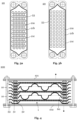
Fig. 2a shows a schematic first bipolar layer according to the present invention in top view; -
Fig. 2b shows a schematic second bipolar layer according to the present invention in top view; -
Fig. 3a shows a schematic perforated layer according to the present invention in top view; -
Fig. 3b shows another schematic perforated layer according to the present invention in top view, and -
Fig. 4 shows a schematic electrolyser with the layer system according to the present invention in side section view. -
Fig. 1 shows alayer system 1 for an electrolyser 100 (cf.Fig. 4 ). Thelayer system 1 comprises abase layer stack 10 having the following layers in the given order: (i) a firstperforated layer 20 with a plurality ofperforations Figs. 3 ); (ii) a firstbipolar layer 30, and (iii) a secondperforated layer 40 with a plurality of perforations. - As further shown in
Fig. 1 , the firstbipolar layer 30 comprises first distancing means 32a, 32b on afirst surface 31 to space the firstperforated layer 20 apart from the firstbipolar layer 30. The first distancing means 32a, 32b abut the firstperforated layer 20. Further, the firstbipolar layer 30 comprises second distancing means 34a, 34b on asecond surface 33 being opposite to thefirst surface 31 to space the secondperforated layer 40 apart from the firstbipolar layer 30. The second distancing means 34a, 34b abut the secondperforated layer 40. The maximum height of the first distancing means 32a, 32b measured from thefirst surface 31 of the firstbipolar layer 30 corresponds to the maximum height of the second distancing means 34a, 34b measured from thesecond surface 33 of the firstbipolar layer 30 multiplied by a value which lies in a range from 0.3 to 0.7. - As shown in
Figs. 1, 2a, and 2b , the first distancing means 32a, 32b, 32c and the second distancing means 34a, 34b, 34c each comprise a plurality of protrusions being integrally formed with the firstbipolar layer 30. For thebipolar layer 30 ofFig. 1 and Fig. 2a said protrusions comprise spherical segments being arranged in a regular pattern. Further, for thebipolar layer 30 ofFig. 2b the protrusions comprise ribs being arranged in a regular pattern, wherein the ribs form flow channels along the firstbipolar layer 30. - Moreover, as depicted in
Figs. 1, 2a, and 2b , the firstbipolar layer 30 has no separate and/or circumferential metal frame attached thereto. - Further, as also depicted in
Figs. 1, 2a, and 2b , thelayer system 1 comprises a firstcircumferential gasket 51 and a secondcircumferential gasket 52. The firstcircumferential gasket 51 is compressed between the firstperforated layer 20 and the firstbipolar layer 30 such that the space between these layers is laterally sealed. The secondcircumferential gasket 52 is compressed between the secondperforated layer 40 and the firstbipolar layer 30 such that the space between these layers is laterally sealed. - Furthermore, as depicted in
Figs. 2a and 2b , the firstbipolar layers 30 each comprise afirst gas outlet 35 being fluidically connected with thefirst surface 31 of the firstbipolar layer 30 and asecond gas outlet 36 being fluidically connected (not explicitly shown) with thesecond surface 33 of the firstbipolar layer 30. Hence, a gas, such as oxygen, between the firstperforated layer 20 and the firstbipolar layer 30 can only exit through thefirst gas outlet 35. Moreover, a gas, such as hydrogen, between the secondperforated layer 40 and the firstbipolar layer 30 can only exit through thesecond gas outlet 36. It is understood that the further openings which lie within the sealed area of the firstbipolar layer 30 may serve to introduce an electrolyte. - As depicted in
Figs. 2a, 2b ,3a, and 3b , the firstbipolar layer 30, the firstperforated layer 20, and the secondperforated layer 40 are substantially rectangular. Hence, they may be punched out of a sheet metal with a reduced amount of waste. -
Fig. 4 shows thelayer system 1 comprised by anelectrolyser 100. Thelayer system 1 comprises two base layer stacks 10, as described above, arranged on top of each other with amembrane 60 between two adjacent perforated layers. It is understood that thelayer system 1 is compressed such that the distancing means of the base layer stacks 10 abut the adjacent perforated layers. Further, between said two adjacent perforated layers, where themembrane 60 is located, a thirdcircumferential gasket 53 is arranged such that the space between these layers is laterally sealed. As shown inFigs. 3a and 3b , the thirdcircumferential gasket 53 is configured such that a fluid transfer through the adjacent perforated layers is only possible via themembrane 60. Thecircumferential gasket 53 also serves to stabilize themembrane 60 between the perforated layers by clamping themembrane 60. In a preferred embodiment said two adjacent perforated layers are laminated together by means of the thirdcircumferential gasket 53 being a rubber lining, wherein the two adjacent perforated layers have substantially the same shape and themembrane 60 is an inlay. - As further shown in
Fig. 4 , theelectrolyser 100 comprises afirst plate 101 with an electrical contacting means and asecond plate 102 with another electrical contacting means. Saidfirst plate 101 and saidsecond plate 102 are connected by screws, i.e., screwed against each other, such that thelayer system 1 between these twoplates -
- 1
- layer system
- 10
- base layer stack
- 20
- first perforated layer
- 21a, 21b, 21c
- perforations
- 30
- first bipolar layer
- 31
- first surface
- 32a, 32b, 32c
- first distancing means
- 34a, 34b, 34c
- second distancing means
- 35
- first gas outlet
- 36
- second gas outlet
- 40
- second perforated layer
- 51
- first circumferential gasket
- 52
- second circumferential gasket
- 53
- third circumferential gasket
- 60
- membrane
- 100
- electrolyser
- 101
- first plate
- 102
- second plate
Claims (15)
- A layer system (1) for an electrolyser (100), wherein the layer system (1) comprises a base layer stack (10) having the following layers in the given order:a first perforated layer (20) with a plurality of perforations (21a, 21b, 21c);a first bipolar layer (30), anda second perforated layer (40) with a plurality of perforations,wherein the first bipolar layer (30) comprises first distancing means (32a, 32b, 32c) on a first surface (31) to space the first perforated layer (20) apart from the first bipolar layer (30), and wherein the first bipolar layer (30) comprises second distancing means (34a, 34b, 34c) on a second surface (33) being opposite to the first surface (31) to space the second perforated layer (40) apart from the first bipolar layer (30).
- The layer system (1) according to the preceding claim, wherein the first distancing means (32a, 32b, 32c) abut the first perforated layer (20) and/or wherein the second distancing means (34a, 34b, 34c) abut the second perforated layer (40).
- The layer system (1) according to any one of the preceding claims, wherein the maximum height of the first distancing means (32a, 32b, 32c) measured from the first surface (31) of the first bipolar layer (30) corresponds to the maximum height of the second distancing means (34a, 34b, 34c) measured from the second surface (33) of the first bipolar layer (30) multiplied by a value which lies in a range from 0.2 to 0.8, preferably from 0.3 to 0.7, and further preferably from 0.4 to 0.6.
- The layer system (1) according to any one of the preceding claims, wherein the first distancing means (32a, 32b, 32c) and/or the second distancing means (34a, 34b, 34c) comprise a plurality of protrusions being integrally formed with the first bipolar layer (30), wherein preferably said protrusions comprise spherical segments, truncated cones, ribs, and/or pins, wherein further preferably the protrusions are arranged in a regular pattern, wherein even further preferably the protrusions form flow channels along the first bipolar layer (30).
- The layer system (1) according to any one of the preceding claims, wherein the layer system (1) comprisesa first circumferential gasket (51) being compressed between the first perforated layer (20) and the first bipolar layer (30) such that the space between these layers is laterally sealed and/ora second circumferential gasket (52) being compressed between the second perforated layer (40) and the first bipolar layer (30) such that the space between these layers is laterally sealed.
- The layer system (1) according to any one of the preceding claims, wherein the first bipolar layer (30) has a thickness which lies in a range from 1 mm to 2 mm, preferably from 1.3 to 1.7 mm, and further preferably from 1.4 mm to 1.6 mm.
- The layer system (1) according to any one of the preceding claims, wherein the first perforated layer (20), the second perforated layer (40) and/or the first bipolar layer (30) are made of a sheet metal respectively, wherein preferably said sheet metal is selected from nickel plated carbon steel, stainless steel 316L, Alloy 200, Alloy 201, and/or Alloy 59.
- The layer system (1) according to any one of the preceding claims, wherein the first perforated layer (20) and/or the second perforated layer (40) are electrode coated, and/or wherein the first bipolar layer (30) is nickel coated.
- The layer system (1) according to any one of the preceding claims, wherein the first bipolar layer (30) has no separate and/or circumferential metal frame attached thereto.
- The layer system (1) according to any one of the preceding claims, wherein the first bipolar layer (30) comprises a first gas outlet (35) being fluidically connected with the first surface (31) of the first bipolar layer (30) and a second gas outlet (36) being fluidically connected with the second surface (33) of the first bipolar layer (30).
- The layer system (1) according to any one of the preceding claims, wherein the first bipolar layer (30), the first perforated layer (20), and/or the second perforated layer (40) are substantially rectangular.
- The layer system (1) according to any one of the preceding claims, wherein the layer system (1) comprises two base layer stacks (10) arranged on top of each other with a membrane (60) between two adjacent perforated layers.
- The layer system (1) according to the preceding claim, wherein the layer system (1) further comprises a third circumferential gasket (53) being arranged between said two adjacent perforated layers such that the space between these layers is laterally sealed, wherein preferably the two adjacent perforated layers are laminated together by means of the third circumferential gasket being a rubber lining, wherein further preferably the two adjacent perforated layers have substantially the same shape.
- The layer system (1) according to any one of claims 12 or 13, wherein the membrane (60) may comprise a nickel oxide diaphragm, a solid polymer electrolyte membrane, a ceramic membrane, an anion exchange membrane, a cation exchange membrane and/or a composite membrane.
- An electrolyser (100) comprising the layer system (1) according to any one of the preceding claims, wherein the electrolyser (100) preferably is an alkaline electrolyser, wherein further preferably the alkaline electrolyser comprises KOH or NaOH.
Priority Applications (2)
| Application Number | Priority Date | Filing Date | Title |
|---|---|---|---|
| EP23178698.9A EP4477780A1 (en) | 2023-06-12 | 2023-06-12 | Layer system for an electrolyser |
| CN202410428074.9A CN119121316A (en) | 2023-06-12 | 2024-04-10 | Layer system for an electrolyzer |
Applications Claiming Priority (1)
| Application Number | Priority Date | Filing Date | Title |
|---|---|---|---|
| EP23178698.9A EP4477780A1 (en) | 2023-06-12 | 2023-06-12 | Layer system for an electrolyser |
Publications (1)
| Publication Number | Publication Date |
|---|---|
| EP4477780A1 true EP4477780A1 (en) | 2024-12-18 |
Family
ID=86760655
Family Applications (1)
| Application Number | Title | Priority Date | Filing Date |
|---|---|---|---|
| EP23178698.9A Withdrawn EP4477780A1 (en) | 2023-06-12 | 2023-06-12 | Layer system for an electrolyser |
Country Status (2)
| Country | Link |
|---|---|
| EP (1) | EP4477780A1 (en) |
| CN (1) | CN119121316A (en) |
Citations (5)
| Publication number | Priority date | Publication date | Assignee | Title |
|---|---|---|---|---|
| US2881123A (en) * | 1955-04-01 | 1959-04-07 | Lonza Ag | Decomposer |
| EP0111149A1 (en) * | 1979-11-29 | 1984-06-20 | De Nora Permelec S.P.A. | Method for electrically connecting valve metal anode ribs and cathodically resistant metal cathode ribs through a bipolar plate, and a bipolar element |
| JPH1081986A (en) * | 1996-09-03 | 1998-03-31 | Permelec Electrode Ltd | Horizontal double-polarity electrolytic cell |
| EP2862960A1 (en) | 2012-06-18 | 2015-04-22 | Asahi Kasei Kabushiki Kaisha | Bipolar alkaline water electrolysis unit and electrolytic cell |
| WO2023104266A1 (en) * | 2021-12-07 | 2023-06-15 | Stiesdal Hydrogen A/S | Electrolyser with a stack of welded four-layer modules |
-
2023
- 2023-06-12 EP EP23178698.9A patent/EP4477780A1/en not_active Withdrawn
-
2024
- 2024-04-10 CN CN202410428074.9A patent/CN119121316A/en active Pending
Patent Citations (5)
| Publication number | Priority date | Publication date | Assignee | Title |
|---|---|---|---|---|
| US2881123A (en) * | 1955-04-01 | 1959-04-07 | Lonza Ag | Decomposer |
| EP0111149A1 (en) * | 1979-11-29 | 1984-06-20 | De Nora Permelec S.P.A. | Method for electrically connecting valve metal anode ribs and cathodically resistant metal cathode ribs through a bipolar plate, and a bipolar element |
| JPH1081986A (en) * | 1996-09-03 | 1998-03-31 | Permelec Electrode Ltd | Horizontal double-polarity electrolytic cell |
| EP2862960A1 (en) | 2012-06-18 | 2015-04-22 | Asahi Kasei Kabushiki Kaisha | Bipolar alkaline water electrolysis unit and electrolytic cell |
| WO2023104266A1 (en) * | 2021-12-07 | 2023-06-15 | Stiesdal Hydrogen A/S | Electrolyser with a stack of welded four-layer modules |
Also Published As
| Publication number | Publication date |
|---|---|
| CN119121316A (en) | 2024-12-13 |
Similar Documents
| Publication | Publication Date | Title |
|---|---|---|
| US6706436B2 (en) | Electrochemical cell design using a bipolar plate | |
| US8337678B2 (en) | Electrochemical apparatus | |
| US11552319B2 (en) | Bipolar plates for use in electrochemical cells | |
| US8894829B2 (en) | Water electrolysis apparatus | |
| US8815063B2 (en) | High-pressure water electrolysis apparatus | |
| US8691060B2 (en) | Water electrolysis apparatus | |
| US9803288B2 (en) | Arrangement of flow structures for use in high differential pressure electrochemical cells | |
| KR20050044679A (en) | Elastic current collector | |
| KR102798368B1 (en) | Fuel cell plate and fluid structure design | |
| JP6526703B2 (en) | Contact method and apparatus for a fuel cell or electrolyzer cell stack | |
| CN115287687B (en) | A sealing structure for an electrolytic cell | |
| US20250236972A1 (en) | Alkaline Electrolyzer with Cooled Bipolar Electrode | |
| US20100206722A1 (en) | Electrolysis apparatus | |
| US20110180398A1 (en) | Water electrolysis apparatus | |
| JP2893238B2 (en) | Water electrolyzer using polymer electrolyte membrane | |
| KR101428523B1 (en) | Gas distributor for water electrolyzing device | |
| WO2025046512A1 (en) | Compressible flow distribution system for electrolyzer plates | |
| CN119121316A (en) | Layer system for an electrolyzer | |
| KR102881830B1 (en) | Stack electrolysis system with integrated catalyst and PTL flow path | |
| KR102916942B1 (en) | Stack electrolysis system with multiple connections | |
| EP4575035A1 (en) | An electrode sheet for transport of liquids and gases | |
| WO2025192602A1 (en) | Cell unit | |
| WO2025192600A1 (en) | Cell unit | |
| GB2632109A (en) | Electrolysers | |
| WO2025181434A1 (en) | A flow field plate, an electrolysis cell, an electrolytic device and methods for preparing the electrode, the electrolysis cell and the electrolytic device |
Legal Events
| Date | Code | Title | Description |
|---|---|---|---|
| PUAI | Public reference made under article 153(3) epc to a published international application that has entered the european phase |
Free format text: ORIGINAL CODE: 0009012 |
|
| STAA | Information on the status of an ep patent application or granted ep patent |
Free format text: STATUS: THE APPLICATION HAS BEEN PUBLISHED |
|
| AK | Designated contracting states |
Kind code of ref document: A1 Designated state(s): AL AT BE BG CH CY CZ DE DK EE ES FI FR GB GR HR HU IE IS IT LI LT LU LV MC ME MK MT NL NO PL PT RO RS SE SI SK SM TR |
|
| STAA | Information on the status of an ep patent application or granted ep patent |
Free format text: STATUS: THE APPLICATION IS DEEMED TO BE WITHDRAWN |
|
| 18D | Application deemed to be withdrawn |
Effective date: 20250619 |