EP4477634A1 - Fabricating methods and apparatuses for a multilayered, nanoparticle-coated fiber material - Google Patents
Fabricating methods and apparatuses for a multilayered, nanoparticle-coated fiber material Download PDFInfo
- Publication number
- EP4477634A1 EP4477634A1 EP24177376.1A EP24177376A EP4477634A1 EP 4477634 A1 EP4477634 A1 EP 4477634A1 EP 24177376 A EP24177376 A EP 24177376A EP 4477634 A1 EP4477634 A1 EP 4477634A1
- Authority
- EP
- European Patent Office
- Prior art keywords
- nanoparticle
- coated
- nanoparticles
- coating
- layer
- Prior art date
- Legal status (The legal status is an assumption and is not a legal conclusion. Google has not performed a legal analysis and makes no representation as to the accuracy of the status listed.)
- Pending
Links
Images




Classifications
-
- D—TEXTILES; PAPER
- D06—TREATMENT OF TEXTILES OR THE LIKE; LAUNDERING; FLEXIBLE MATERIALS NOT OTHERWISE PROVIDED FOR
- D06M—TREATMENT, NOT PROVIDED FOR ELSEWHERE IN CLASS D06, OF FIBRES, THREADS, YARNS, FABRICS, FEATHERS OR FIBROUS GOODS MADE FROM SUCH MATERIALS
- D06M11/00—Treating fibres, threads, yarns, fabrics or fibrous goods made from such materials, with inorganic substances or complexes thereof; Such treatment combined with mechanical treatment, e.g. mercerising
- D06M11/73—Treating fibres, threads, yarns, fabrics or fibrous goods made from such materials, with inorganic substances or complexes thereof; Such treatment combined with mechanical treatment, e.g. mercerising with carbon or compounds thereof
- D06M11/74—Treating fibres, threads, yarns, fabrics or fibrous goods made from such materials, with inorganic substances or complexes thereof; Such treatment combined with mechanical treatment, e.g. mercerising with carbon or compounds thereof with carbon or graphite; with carbides; with graphitic acids or their salts
-
- C—CHEMISTRY; METALLURGY
- C04—CEMENTS; CONCRETE; ARTIFICIAL STONE; CERAMICS; REFRACTORIES
- C04B—LIME, MAGNESIA; SLAG; CEMENTS; COMPOSITIONS THEREOF, e.g. MORTARS, CONCRETE OR LIKE BUILDING MATERIALS; ARTIFICIAL STONE; CERAMICS; REFRACTORIES; TREATMENT OF NATURAL STONE
- C04B35/00—Shaped ceramic products characterised by their composition; Ceramics compositions; Processing powders of inorganic compounds preparatory to the manufacturing of ceramic products
- C04B35/622—Forming processes; Processing powders of inorganic compounds preparatory to the manufacturing of ceramic products
- C04B35/626—Preparing or treating the powders individually or as batches ; preparing or treating macroscopic reinforcing agents for ceramic products, e.g. fibres; mechanical aspects section B
- C04B35/628—Coating the powders or the macroscopic reinforcing agents
- C04B35/62844—Coating fibres
- C04B35/62857—Coating fibres with non-oxide ceramics
- C04B35/62873—Carbon
-
- B—PERFORMING OPERATIONS; TRANSPORTING
- B05—SPRAYING OR ATOMISING IN GENERAL; APPLYING FLUENT MATERIALS TO SURFACES, IN GENERAL
- B05D—PROCESSES FOR APPLYING FLUENT MATERIALS TO SURFACES, IN GENERAL
- B05D7/00—Processes, other than flocking, specially adapted for applying liquids or other fluent materials to particular surfaces or for applying particular liquids or other fluent materials
- B05D7/50—Multilayers
- B05D7/52—Two layers
-
- B—PERFORMING OPERATIONS; TRANSPORTING
- B05—SPRAYING OR ATOMISING IN GENERAL; APPLYING FLUENT MATERIALS TO SURFACES, IN GENERAL
- B05D—PROCESSES FOR APPLYING FLUENT MATERIALS TO SURFACES, IN GENERAL
- B05D1/00—Processes for applying liquids or other fluent materials
- B05D1/007—Processes for applying liquids or other fluent materials using an electrostatic field
-
- B—PERFORMING OPERATIONS; TRANSPORTING
- B05—SPRAYING OR ATOMISING IN GENERAL; APPLYING FLUENT MATERIALS TO SURFACES, IN GENERAL
- B05D—PROCESSES FOR APPLYING FLUENT MATERIALS TO SURFACES, IN GENERAL
- B05D7/00—Processes, other than flocking, specially adapted for applying liquids or other fluent materials to particular surfaces or for applying particular liquids or other fluent materials
- B05D7/24—Processes, other than flocking, specially adapted for applying liquids or other fluent materials to particular surfaces or for applying particular liquids or other fluent materials for applying particular liquids or other fluent materials
-
- C—CHEMISTRY; METALLURGY
- C04—CEMENTS; CONCRETE; ARTIFICIAL STONE; CERAMICS; REFRACTORIES
- C04B—LIME, MAGNESIA; SLAG; CEMENTS; COMPOSITIONS THEREOF, e.g. MORTARS, CONCRETE OR LIKE BUILDING MATERIALS; ARTIFICIAL STONE; CERAMICS; REFRACTORIES; TREATMENT OF NATURAL STONE
- C04B35/00—Shaped ceramic products characterised by their composition; Ceramics compositions; Processing powders of inorganic compounds preparatory to the manufacturing of ceramic products
- C04B35/622—Forming processes; Processing powders of inorganic compounds preparatory to the manufacturing of ceramic products
- C04B35/626—Preparing or treating the powders individually or as batches ; preparing or treating macroscopic reinforcing agents for ceramic products, e.g. fibres; mechanical aspects section B
- C04B35/628—Coating the powders or the macroscopic reinforcing agents
- C04B35/62892—Coating the powders or the macroscopic reinforcing agents with a coating layer consisting of particles
-
- C—CHEMISTRY; METALLURGY
- C04—CEMENTS; CONCRETE; ARTIFICIAL STONE; CERAMICS; REFRACTORIES
- C04B—LIME, MAGNESIA; SLAG; CEMENTS; COMPOSITIONS THEREOF, e.g. MORTARS, CONCRETE OR LIKE BUILDING MATERIALS; ARTIFICIAL STONE; CERAMICS; REFRACTORIES; TREATMENT OF NATURAL STONE
- C04B35/00—Shaped ceramic products characterised by their composition; Ceramics compositions; Processing powders of inorganic compounds preparatory to the manufacturing of ceramic products
- C04B35/622—Forming processes; Processing powders of inorganic compounds preparatory to the manufacturing of ceramic products
- C04B35/626—Preparing or treating the powders individually or as batches ; preparing or treating macroscopic reinforcing agents for ceramic products, e.g. fibres; mechanical aspects section B
- C04B35/628—Coating the powders or the macroscopic reinforcing agents
- C04B35/62894—Coating the powders or the macroscopic reinforcing agents with more than one coating layer
-
- C—CHEMISTRY; METALLURGY
- C04—CEMENTS; CONCRETE; ARTIFICIAL STONE; CERAMICS; REFRACTORIES
- C04B—LIME, MAGNESIA; SLAG; CEMENTS; COMPOSITIONS THEREOF, e.g. MORTARS, CONCRETE OR LIKE BUILDING MATERIALS; ARTIFICIAL STONE; CERAMICS; REFRACTORIES; TREATMENT OF NATURAL STONE
- C04B35/00—Shaped ceramic products characterised by their composition; Ceramics compositions; Processing powders of inorganic compounds preparatory to the manufacturing of ceramic products
- C04B35/622—Forming processes; Processing powders of inorganic compounds preparatory to the manufacturing of ceramic products
- C04B35/626—Preparing or treating the powders individually or as batches ; preparing or treating macroscopic reinforcing agents for ceramic products, e.g. fibres; mechanical aspects section B
- C04B35/628—Coating the powders or the macroscopic reinforcing agents
- C04B35/62897—Coatings characterised by their thickness
-
- C—CHEMISTRY; METALLURGY
- C04—CEMENTS; CONCRETE; ARTIFICIAL STONE; CERAMICS; REFRACTORIES
- C04B—LIME, MAGNESIA; SLAG; CEMENTS; COMPOSITIONS THEREOF, e.g. MORTARS, CONCRETE OR LIKE BUILDING MATERIALS; ARTIFICIAL STONE; CERAMICS; REFRACTORIES; TREATMENT OF NATURAL STONE
- C04B35/00—Shaped ceramic products characterised by their composition; Ceramics compositions; Processing powders of inorganic compounds preparatory to the manufacturing of ceramic products
- C04B35/71—Ceramic products containing macroscopic reinforcing agents
- C04B35/78—Ceramic products containing macroscopic reinforcing agents containing non-metallic materials
- C04B35/80—Fibres, filaments, whiskers, platelets, or the like
-
- C—CHEMISTRY; METALLURGY
- C04—CEMENTS; CONCRETE; ARTIFICIAL STONE; CERAMICS; REFRACTORIES
- C04B—LIME, MAGNESIA; SLAG; CEMENTS; COMPOSITIONS THEREOF, e.g. MORTARS, CONCRETE OR LIKE BUILDING MATERIALS; ARTIFICIAL STONE; CERAMICS; REFRACTORIES; TREATMENT OF NATURAL STONE
- C04B35/00—Shaped ceramic products characterised by their composition; Ceramics compositions; Processing powders of inorganic compounds preparatory to the manufacturing of ceramic products
- C04B35/71—Ceramic products containing macroscopic reinforcing agents
- C04B35/78—Ceramic products containing macroscopic reinforcing agents containing non-metallic materials
- C04B35/80—Fibres, filaments, whiskers, platelets, or the like
- C04B35/83—Carbon fibres in a carbon matrix
-
- D—TEXTILES; PAPER
- D01—NATURAL OR MAN-MADE THREADS OR FIBRES; SPINNING
- D01F—CHEMICAL FEATURES IN THE MANUFACTURE OF ARTIFICIAL FILAMENTS, THREADS, FIBRES, BRISTLES OR RIBBONS; APPARATUS SPECIALLY ADAPTED FOR THE MANUFACTURE OF CARBON FILAMENTS
- D01F9/00—Artificial filaments or the like of other substances; Manufacture thereof; Apparatus specially adapted for the manufacture of carbon filaments
-
- D—TEXTILES; PAPER
- D06—TREATMENT OF TEXTILES OR THE LIKE; LAUNDERING; FLEXIBLE MATERIALS NOT OTHERWISE PROVIDED FOR
- D06B—TREATING TEXTILE MATERIALS USING LIQUIDS, GASES OR VAPOURS
- D06B3/00—Passing of textile materials through liquids, gases or vapours to effect treatment, e.g. washing, dyeing, bleaching, sizing, impregnating
- D06B3/10—Passing of textile materials through liquids, gases or vapours to effect treatment, e.g. washing, dyeing, bleaching, sizing, impregnating of fabrics
-
- D—TEXTILES; PAPER
- D06—TREATMENT OF TEXTILES OR THE LIKE; LAUNDERING; FLEXIBLE MATERIALS NOT OTHERWISE PROVIDED FOR
- D06M—TREATMENT, NOT PROVIDED FOR ELSEWHERE IN CLASS D06, OF FIBRES, THREADS, YARNS, FABRICS, FEATHERS OR FIBROUS GOODS MADE FROM SUCH MATERIALS
- D06M10/00—Physical treatment of fibres, threads, yarns, fabrics or fibrous goods made from such materials, e.g. by ultrasonic waves, corona discharge, irradiation, electric currents or magnetic fields; Physical treatment combined with treatment with chemical compounds or elements
- D06M10/04—Physical treatment combined with treatment with chemical compounds or elements
- D06M10/06—Inorganic compounds or elements
-
- D—TEXTILES; PAPER
- D06—TREATMENT OF TEXTILES OR THE LIKE; LAUNDERING; FLEXIBLE MATERIALS NOT OTHERWISE PROVIDED FOR
- D06M—TREATMENT, NOT PROVIDED FOR ELSEWHERE IN CLASS D06, OF FIBRES, THREADS, YARNS, FABRICS, FEATHERS OR FIBROUS GOODS MADE FROM SUCH MATERIALS
- D06M11/00—Treating fibres, threads, yarns, fabrics or fibrous goods made from such materials, with inorganic substances or complexes thereof; Such treatment combined with mechanical treatment, e.g. mercerising
- D06M11/32—Treating fibres, threads, yarns, fabrics or fibrous goods made from such materials, with inorganic substances or complexes thereof; Such treatment combined with mechanical treatment, e.g. mercerising with oxygen, ozone, ozonides, oxides, hydroxides or percompounds; Salts derived from anions with an amphoteric element-oxygen bond
- D06M11/36—Treating fibres, threads, yarns, fabrics or fibrous goods made from such materials, with inorganic substances or complexes thereof; Such treatment combined with mechanical treatment, e.g. mercerising with oxygen, ozone, ozonides, oxides, hydroxides or percompounds; Salts derived from anions with an amphoteric element-oxygen bond with oxides, hydroxides or mixed oxides; with salts derived from anions with an amphoteric element-oxygen bond
- D06M11/46—Oxides or hydroxides of elements of Groups 4 or 14 of the Periodic Table; Titanates; Zirconates; Stannates; Plumbates
-
- D—TEXTILES; PAPER
- D06—TREATMENT OF TEXTILES OR THE LIKE; LAUNDERING; FLEXIBLE MATERIALS NOT OTHERWISE PROVIDED FOR
- D06M—TREATMENT, NOT PROVIDED FOR ELSEWHERE IN CLASS D06, OF FIBRES, THREADS, YARNS, FABRICS, FEATHERS OR FIBROUS GOODS MADE FROM SUCH MATERIALS
- D06M11/00—Treating fibres, threads, yarns, fabrics or fibrous goods made from such materials, with inorganic substances or complexes thereof; Such treatment combined with mechanical treatment, e.g. mercerising
- D06M11/77—Treating fibres, threads, yarns, fabrics or fibrous goods made from such materials, with inorganic substances or complexes thereof; Such treatment combined with mechanical treatment, e.g. mercerising with silicon or compounds thereof
-
- D—TEXTILES; PAPER
- D06—TREATMENT OF TEXTILES OR THE LIKE; LAUNDERING; FLEXIBLE MATERIALS NOT OTHERWISE PROVIDED FOR
- D06M—TREATMENT, NOT PROVIDED FOR ELSEWHERE IN CLASS D06, OF FIBRES, THREADS, YARNS, FABRICS, FEATHERS OR FIBROUS GOODS MADE FROM SUCH MATERIALS
- D06M11/00—Treating fibres, threads, yarns, fabrics or fibrous goods made from such materials, with inorganic substances or complexes thereof; Such treatment combined with mechanical treatment, e.g. mercerising
- D06M11/80—Treating fibres, threads, yarns, fabrics or fibrous goods made from such materials, with inorganic substances or complexes thereof; Such treatment combined with mechanical treatment, e.g. mercerising with boron or compounds thereof, e.g. borides
-
- D—TEXTILES; PAPER
- D06—TREATMENT OF TEXTILES OR THE LIKE; LAUNDERING; FLEXIBLE MATERIALS NOT OTHERWISE PROVIDED FOR
- D06M—TREATMENT, NOT PROVIDED FOR ELSEWHERE IN CLASS D06, OF FIBRES, THREADS, YARNS, FABRICS, FEATHERS OR FIBROUS GOODS MADE FROM SUCH MATERIALS
- D06M23/00—Treatment of fibres, threads, yarns, fabrics or fibrous goods made from such materials, characterised by the process
- D06M23/08—Processes in which the treating agent is applied in powder or granular form
-
- C—CHEMISTRY; METALLURGY
- C04—CEMENTS; CONCRETE; ARTIFICIAL STONE; CERAMICS; REFRACTORIES
- C04B—LIME, MAGNESIA; SLAG; CEMENTS; COMPOSITIONS THEREOF, e.g. MORTARS, CONCRETE OR LIKE BUILDING MATERIALS; ARTIFICIAL STONE; CERAMICS; REFRACTORIES; TREATMENT OF NATURAL STONE
- C04B2235/00—Aspects relating to ceramic starting mixtures or sintered ceramic products
- C04B2235/02—Composition of constituents of the starting material or of secondary phases of the final product
- C04B2235/50—Constituents or additives of the starting mixture chosen for their shape or used because of their shape or their physical appearance
- C04B2235/52—Constituents or additives characterised by their shapes
- C04B2235/5208—Fibers
- C04B2235/5216—Inorganic
- C04B2235/524—Non-oxidic, e.g. borides, carbides, silicides or nitrides
- C04B2235/5248—Carbon, e.g. graphite
-
- C—CHEMISTRY; METALLURGY
- C04—CEMENTS; CONCRETE; ARTIFICIAL STONE; CERAMICS; REFRACTORIES
- C04B—LIME, MAGNESIA; SLAG; CEMENTS; COMPOSITIONS THEREOF, e.g. MORTARS, CONCRETE OR LIKE BUILDING MATERIALS; ARTIFICIAL STONE; CERAMICS; REFRACTORIES; TREATMENT OF NATURAL STONE
- C04B2235/00—Aspects relating to ceramic starting mixtures or sintered ceramic products
- C04B2235/60—Aspects relating to the preparation, properties or mechanical treatment of green bodies or pre-forms
- C04B2235/616—Liquid infiltration of green bodies or pre-forms
-
- D—TEXTILES; PAPER
- D06—TREATMENT OF TEXTILES OR THE LIKE; LAUNDERING; FLEXIBLE MATERIALS NOT OTHERWISE PROVIDED FOR
- D06M—TREATMENT, NOT PROVIDED FOR ELSEWHERE IN CLASS D06, OF FIBRES, THREADS, YARNS, FABRICS, FEATHERS OR FIBROUS GOODS MADE FROM SUCH MATERIALS
- D06M2101/00—Chemical constitution of the fibres, threads, yarns, fabrics or fibrous goods made from such materials, to be treated
- D06M2101/40—Fibres of carbon
-
- D—TEXTILES; PAPER
- D06—TREATMENT OF TEXTILES OR THE LIKE; LAUNDERING; FLEXIBLE MATERIALS NOT OTHERWISE PROVIDED FOR
- D06M—TREATMENT, NOT PROVIDED FOR ELSEWHERE IN CLASS D06, OF FIBRES, THREADS, YARNS, FABRICS, FEATHERS OR FIBROUS GOODS MADE FROM SUCH MATERIALS
- D06M2400/00—Specific information on the treatment or the process itself not provided in D06M23/00-D06M23/18
Definitions
- the present disclosure generally relates to coated materials and, more particularly, to fabricating methods and apparatuses for a multilayered, nanoparticle-coated fiber material.
- Materials containing one or more coated layers, such as coated fibers, made by known fabricating methods are prone to unevenness of the one or more coated layers.
- pyrolytic-carbon (pyC) coatings on fibers are prone to unevenness of one or more coatings, resulting in variable composite-material strength when the coated fibers are combined with ceramic matrices to make ceramic-matrix composites (CMCs).
- the intent of pyC coatings in CMCs is to create a weak interface between the matrix and the fiber to allow for the fiber to move relative to the matrix under certain loads, thereby allowing the composite to deform and carry more load than is possible with a strong fiber-matrix interface.
- pyC coatings need to be applied using chemical vapor deposition (CVD), which requires specialized equipment and controlled temperature and pressure.
- CVD chemical vapor deposition
- coated materials such as coated-fiber materials used in making CMCs.
- the disclosed fabricating method preferably a fabricating method for fabricating a multilayered, nanoparticle-coated fiber material using a layer-by-layer nanoparticle-deposition system, includes coating a fiber substrate with a first type of nanoparticle to provide a first coated layer of the multilayered, nanoparticle-coated fiber material. Fabrication also includes coating the first coated layer with a second type of nanoparticle to provide a second coated layer of the multilayered, nanoparticle-coated fiber material.
- the method may comprise coating the second coated layer with a third type of nanoparticle to provide a third coated layer of the multilayered, nanoparticle-coated fiber material.
- One or both of the first type of nanoparticle and the second type of nanoparticle may comprise high-temperature nanoparticles.
- the high-temperature nanoparticles comprise graphene nanoparticles
- the fiber substrate comprises carbon fiber material.
- Layer-by-layer nanoparticle-deposition may be performed in a manner so as to deposit nanoparticles onto surfaces of fibers comprising the fiber substrate.
- the layer-by-layer deposition may be performed at ambient or near-ambient conditions.
- the method may further comprise rinsing the first coated layer to form a monolayer of the first coated layer, and rinsing the second coated layer to form a monolayer of the second coated layer.
- each layer of the first and second coated layers has a thickness between about 5 nanometers and about 1000 nanometers.
- the method may further comprise coating the second coated layer with a third type of nanoparticle to provide a third coated layer of the multilayered, nanoparticle-coated fiber material.
- the third type of nanoparticle is the same type as the first type of nanoparticle.
- the method may further comprise treating a surface of each of a plurality of fibers of the fiber substrate to impart an ionic charge polarity onto the surface.
- the step of coating a fiber substrate with a first type of nanoparticle comprises coating the surface of each of the plurality of fibers of the fiber substrate with nanoparticles having an ionic charge polarity opposite the ionic charge polarity of the surface of each of the plurality of fibers of the fiber substrate.
- the step of coating the first coated layer with a second type of nanoparticle comprises coating the first layer with nanoparticles having an ionic charge polarity opposite the ionic charge polarity of the first layer.
- a carbon fiber is provided that is fabricated according to the fabricating method of the first aspect.
- the disclosed fabricating method includes treating a surface of each of a plurality of fibers, preferably fibers of a fiber substrate, to impart an ionic charge polarity onto the surface. Fabrication also includes coating the surface of each of the plurality of fibers, preferably the fibers of the fiber substrate, with nanoparticles having an ionic charge polarity opposite the ionic charge polarity of the surface of each of the plurality of fibers, preferably the fibers of the fiber substrate, to provide a first layer of a multilayered, nanoparticle-coated plurality of fibers and/or a multilayered, nanoparticle-coated fiber material.
- Fabrication further includes coating the first layer with nanoparticles having an ionic charge polarity opposite the ionic charge polarity of the first layer to provide a second layer of the multilayered, nanoparticle-coated plurality of fibers and/or the multilayered, nanoparticle-coated fiber material.
- the method may further comprise rinsing the first layer to form a monolayer of the first layer, and rinsing the second layer to form a monolayer of the second layer, wherein each of the monolayers of the first and second layers has a thickness between about 5 nanometers and about 1000 nanometers.
- the method may further comprise spreading the plurality of fibers of the fiber substrate to maximize surface areas that can be coated with nanoparticles.
- the method may further comprise drying each of the first and second layers to modify a combination of handling and usage properties of the multilayered, nanoparticle-coated fiber material.
- a ceramic-matrix composite is provided that is made according to the method of the third aspect.
- fabricating apparatuses for a multilayered, nanoparticle-coated fiber material are also disclosed.
- the fabricating apparatus includes a first coating vessel containing a first nanoparticle-based solution, through which a substrate, preferably a fiber substrate, can pass to impart a first coating of nanoparticles onto the substrate, preferably the fiber substrate.
- the fabricating apparatus also includes a second coating vessel containing a second nanoparticle-based solution through which the substrate, preferably the fiber substrate, with the first coating of nanoparticles can pass to impart a second coating of nanoparticles onto the substrate, preferably the fiber substrate, coated with the first coating of nanoparticles and thereby to provide the multilayered, nanoparticle-coated fiber material.
- the fiber substrate may have an ionic charge polarity
- nanoparticles contained in the first coating vessel may have an ionic charge polarity opposite the ionic charge polarity of the fiber substrate
- nanoparticles contained in the second coating vessel may have an ionic charge polarity like the ionic charge polarity of the fiber substrate.
- the first nanoparticle-based solution may include a polymer that may act as a carrying agent for nanoparticles contained in the first coating vessel
- the second nanoparticle-based solution may include a polymer that may act as a carrying agent for the nanoparticles contained in the second coating vessel.
- Nanoparticles contained in each of the first and second coating vessels may be selected from a combination of graphene, BN, SiN, TiC, and TiO 2 .
- the fabricating apparatus may further comprise a first rinsing vessel containing a rinsing solution for rinsing the fiber substrate imparted with the first coating of nanoparticles to form a monolayer of the first coating of nanoparticles, and a second rinsing vessel containing a rinsing solution for rinsing the fiber substrate coated with the second coating of nanoparticles to form a monolayer of the second coating of nanoparticles.
- each of the monolayers of the first and second coatings of nanoparticles has a thickness between about five nanometers and about 100 nanometers.
- the apparatus further comprises a third coating vessel containing a third nanoparticle-based solution through which the fiber substrate with the first and second coatings of nanoparticles can pass to impart a third coating of nanoparticles onto the fiber substrate coated with the first and second coatings of nanoparticles and thereby to provide a thicker multilayered, nanoparticle-coated fiber material, and optionally further comprising a third rinsing vessel containing a rinsing solution for rinsing the fiber substrate coated with the third coating of nanoparticles to form a monolayer of the third coating of nanoparticles.
- the present application is directed to fabrication apparatuses and methods using a layer-by-layer (LBL) deposition system.
- LBL layer-by-layer
- the specific construction of an apparatus and method therefor and the industry in which the apparatus and method are implemented may vary. It is to be understood that the disclosure below provides a number of examples for implementing different features of various examples. Specific examples of components and arrangements are described to simplify the present disclosure. These are merely examples and are not intended to be limiting.
- the disclosure below describes a fabrication apparatus and method for a multilayered, nanoparticle-coated fiber material that is used in the manufacture of aerospace parts.
- the apparatus and method may be implemented by an original equipment manufacturer (OEM) in compliance with military and space regulations. It is conceivable that the disclosed apparatus and method may be implemented in many other industries.
- OEM original equipment manufacturer
- the layer-by-layer deposition system 10 embodies an apparatus 100 for fabricating a multilayered, nanoparticle-coated fiber material and constructed in accordance with an example implementation.
- An example fiber material comprises carbon fiber material. Other types of fiber material are possible.
- the fabricating apparatus 100 includes a first coating vessel 110 containing a first nanoparticle-based solution 112 through which a fiber substrate 102 (e.g., a carbon-fiber material) can pass along a pathway 104 (e.g., a fiber-production line or a fiber-handling pathway that uses roll-to-roll processing) to impart a first coating of nanoparticles 114 onto the fiber substrate 102 to provide a first coated substrate 116.
- a fiber substrate 102 e.g., a carbon-fiber material
- a pathway 104 e.g., a fiber-production line or a fiber-handling pathway that uses roll-to-roll processing
- the fiber substrate 102 is imparted with the first coating of nanoparticles 114 to form a monolayer of the first coating of nanoparticles 114.
- the fiber substrate 102 has an ionic charge polarity (i.e., either a cationic charge or an anionic charge), and can be treated (e.g., an acid or base wash, or plasma) to impart such ionic charge.
- Nanoparticles contained in the first coating vessel 110 have an ionic charge polarity opposite the ionic charge polarity of the fiber substrate 102.
- Nanoparticles contained in the first coating vessel 110 may be selected from graphene, BN, SiN, TiC, TiO 2 , and combinations and mixtures thereof. Other types of nanoparticle materials are possible.
- the first nanoparticle-based solution 112 includes a polymer that acts as a carrying agent for the nanoparticles contained in the first coating vessel 110.
- the fabricating apparatus 100 also includes a first rinsing vessel 120 containing a rinsing solution 122 (e.g., an aqueous solution) for rinsing the first coated substrate 116 to provide a first rinsed coated substrate 124, which is then allowed to dry. Drying may be performed at ambient conditions or at an elevated temperature.
- a rinsing solution 122 e.g., an aqueous solution
- Drying may be performed at ambient conditions or at an elevated temperature.
- An example relationship between the first coating vessel 110 and the first rinsing vessel 120 is shown in Fig. 2B , wherein a number of rollers 125 are used to provide a production-line type of setup.
- the first rinsing vessel 120 contains a solution possessing no nanoparticles, through which the fiber substrate 102 with the first coating of nanoparticles 114 can pass to remove excess nanoparticles from the first coating of nanoparticles 114 from the fiber substrate 102, leaving only those adhered to the fiber substrate 102.
- the first rinsed coated substrate 124 forms a monolayer of the first coating of nanoparticles 114.
- the monolayer of the first coating of nanoparticles 114 has a thickness between about 5 nanometers and about 1000 nanometers, such as from about 100 nanometers to about 500 nanometers, or from about 200 nanometers to about 400 nanometers.
- the fabricating apparatus 100 further includes a second coating vessel 130 containing a second nanoparticle-based solution 132 through which the first rinsed coated substrate 124 can pass to impart a second coating of nanoparticles 134 onto the first rinsed coated substrate 124 to provide a second coated substrate 136.
- Nanoparticles contained in the second coating vessel 130 have an ionic charge polarity like the ionic charge polarity of the fiber substrate 102 (e.g., carbon fiber), and thus an ionic charge polarity that is opposite the ionic charge polarity of the nanoparticles contained in the first coating vessel 110.
- Nanoparticles contained in the second coating vessel 130 may be selected from at least one of graphene, BN, SiN, TiC, TiO 2 , and mixtures or combinations thereof. Other types of nanoparticle materials are possible.
- the second nanoparticle-based solution 132 includes a polymer that acts as a carrying agent for the nanoparticles contained in the second coating vessel 130.
- the fabricating apparatus 100 also includes a second rinsing vessel 140 containing a rinsing solution 142 (e.g., an aqueous solution) for rinsing the second coated substrate 136 to provide a second rinsed coated substrate 144, which is then allowed to dry (e.g., at ambient conditions or at an elevated temperature).
- a rinsing solution 142 e.g., an aqueous solution
- the second rinsing vessel 140 contains a second nanoparticle-free solution through which the fiber substrate 102 with the first and second coatings of nanoparticles 114, 134 can pass to remove the excess particles from the second coating of nanoparticles 134 from the fiber substrate 102 coated with the first coating of nanoparticles 114 to leave only the nanoparticles from the second coating that are adhered to the nanoparticles from the first coating, which are adhered to the fiber substrate 102.
- the second rinsed coated substrate 144 forms a monolayer of the second coating of nanoparticles 134.
- the monolayer of the second coating of nanoparticles 134 has a thickness between about 5 nanometers and about 1000 nanometers, such as from about 100 nanometers to about 500 nanometers, or from about 200 nanometers to about 400 nanometers.
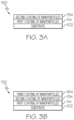
- a schematic elevational view of different layers of the fabricated, multilayered, nanoparticle-coated fiber material 150 is illustrated.
- the monolayer of the first coating of nanoparticles 114 is disposed on the fiber substrate 102, and the monolayer of the second coating of nanoparticles 134 is disposed on first coating of nanoparticles 114. Since the monolayer of the first coating of nanoparticles 114 has an ionic charge polarity that is opposite to the ionic charge polarity of the fiber substrate 102 and ionic charge polarity of the second coating of nanoparticles 134, strong bonds are provided with the layers above and below.
- the fabricating apparatus 100 may further comprise a third coating vessel 160 containing a third nanoparticle-based solution 162 through which the second rinsed coated substrate 144 can pass to impart a third coating of nanoparticles 164 onto the second rinsed coated substrate 144 to provide a third coated substrate 166.
- the fabricating apparatus 100 also comprises a third rinsing vessel 170 containing a rinsing solution 172 (e.g., an aqueous solution) for rinsing the third coated substrate 166 to provide a third rinsed, coated substrate 174, which is then allowed to dry.
- the dried, third, rinsed, coated substrate 174 comprises a thicker multilayered, nanoparticle-coated fiber material 152.
- the thicker multilayered, nanoparticle-coated fiber material 152 as shown in Fig.
- 3B has another monolayer of nanoparticles (i.e., the third coating of nanoparticles 164) in addition to the monolayer of the first coating of nanoparticles 114 and the monolayer of the second coating of nanoparticles 134 on the fiber substrate 102.
- the production pathway and vessels may be arranged to allow the fibers to be exposed to the same nanoparticle solution or the same rinsing solution multiple times to minimize the number of solution vessels and rinsing vessels needed so as to minimize the size of the setup.
- An example minimal-size production-line setup is shown in Fig. 2C .
- the first coating vessel 110, the first rinsing vessel 120, the second coating vessel 130, and the second rinsing vessel 140 are arranged in a circular-shaped production-line setup that can be repeated as many times as desired.
- excess nanoparticles contained in rinsing vessels can be removed and recycled to minimize costs.
- a layer-by-layer deposition system is arranged to impart multiple nanoparticle-coated layers onto fibers to create desired interface coatings between layers.
- the coating layers may comprise high-temperature materials, such as graphene nanoplatelets to create desirable weak interface coatings when fibers are to be coupled with ceramic matrices to form ceramic-matrix composites.
- Each coating layer is self-assembled due to particle shape and electrical charge, and is deposited individually over the prior coating layer.
- the number of coating depositions can be repeated as many times as desired or needed, such as three times or five times. Other numbers of coating layers are possible.
- Each coating layer is also substantially uniform in thickness throughout to provide a substantially uniform strength with low variability along the length of each layer.
- Post-processing may include exposure to heat, ultraviolet light, or other means to modify coatings so as to have more desirable handling properties or more desirable usage properties than the unprocessed fiber material.
- the fabricated multilayered, nanoparticle-coated fiber material 150, 152 may be put onto a creel to produce fabric that comprises fibers coated with nanoparticles.
- the fabricated, multilayered, nanoparticle-coated fiber material 150, 152 may be used as a reinforcement in a ceramic matrix for making composites.
- Post-processing equipment may be located at the end of the fiber-production line such as shown in Fig. 2A , or at a location that is away from the fiber-production line.
- an example post-processing setup 180 that can be used following the fabricating apparatus 100 of Fig. 2A is illustrated.
- the fabricated, multilayered, nanoparticle-coated fiber material 150, 152 of Fig. 3A or Fig. 3B is formed into a desired part shape before being subjected to a pyrolysis process in block 184.
- a chemical vapor infiltration/chemical vapor deposition (CVI/CVD) process as needed can be applied before being subjected to another pyrolysis process as shown in block 188.
- the process of block 186 and the process of block 188 can also be repeated as many times as desired or needed before a fully-densified part 190 is provided by the post-processing setup 180.
- a flow diagram 400 of a fabricating method for a multilayered, nanoparticle-coated fibers using layer-by-layer, nanoparticle deposition in accordance with an example implementation is illustrated.
- a fiber substrate is coated with a first type of nanoparticle to provide a first coated layer of a multilayered, nanoparticle-coated fiber material.
- the process proceeds to block 420 in which the first coated layer is coated with a second type of nanoparticle to provide a second coated layer of the multilayered, nanoparticle-coated fiber material.
- the process then ends.
- one or both of the first type of nanoparticle and the second type of nanoparticle comprise high-temperature nanoparticles.
- the high-temperature nanoparticles comprise graphene nanoparticles.
- the layer-by-layer deposition is performed in a manner so as to deposit the nanoparticles onto surfaces of the fibers comprising a fabric.
- the layer-by-layer deposition is performed at ambient or near-ambient conditions.
- fabrication further comprises rinsing the first coated layer to form a monolayer of the first coated layer, and rinsing the second coated layer to form a monolayer of the second coated layer.
- each of the monolayers of the first and second coated layers has a thickness between about five nanometers and about 100 nanometers.
- fabrication further comprises coating the second coated layer with a third type of nanoparticle to provide a third coated layer of the multilayered, nanoparticle-coated material.
- the third type of nanoparticle is the same type as the first type of nanoparticle.
- a carbon fiber is formed according to the disclosed fabrication method of Fig. 4 .
- a flow diagram 500 of a fabrication method in accordance with another example implementation is illustrated.
- a surface of each of a plurality of fibers is treated to impart an ionic charge polarity onto the surface.
- the process proceeds to block 520 in which the surface of each of the plurality of fibers is coated with nanoparticles having an ionic charge polarity opposite the ionic charge polarity of the surface of each of the plurality of fibers to provide a first layer of a multilayered, nanoparticle-coated plurality of fibers.
- the first layer is coated with nanoparticles having an ionic charge polarity opposite the ionic charge polarity of the first layer to provide a second layer of the multilayered, nanoparticle-coated plurality of fibers. The process then ends.
- fabrication further comprises rinsing the first layer to form a monolayer of the first layer, and rinsing the second layer to form a monolayer of the second layer.
- Each of the monolayers of the first and second layers has a thickness between about five nanometers and about 100 nanometers.
- fabrication further comprises spreading the plurality of fibers to maximize surface areas that can be coated with nanoparticles.
- fabrication further comprises drying each of the first and second layers to modify a combination of handling and usage properties of the multilayered, nanoparticle-coated plurality of fibers.
- a ceramic-matrix composite is made according to the disclosed fabrication method of Fig. 5 .
- a number of advantages are provided by fabricating a multilayered, nanoparticle-coated fiber material as disclosed herein.
- One advantage is that high-temperature nanoparticles can be applied onto fibers at ambient or near-ambient conditions.
- Another advantage is that very dense coatings of nanoparticles can be formed on fibers.
- Still another advantage is that no specialized (and therefore usually expensive) equipment as well as no highly controlled conditions (e.g., temperature and pressure) are required to fabricate multilayered, nanoparticle-coated fibers disclosed herein.
- Yet another advantage is that no batch processing is required, since the quantity of multilayered, nanoparticle-coated fiber material can be obtained as needed along a production-line setup, such as illustrated in Fig. 2A .
- the aircraft manufacturing and service method 1100 may include specification and design 1104 of the aircraft 1102 and material procurement 1106.
- component/subassembly manufacturing 1108 and system integration 1110 of the aircraft 1102 takes place.
- the aircraft 1102 may go through certification and delivery 1112 in order to be placed in service 1114.
- routine maintenance and service 1116 which may also include modification, reconfiguration, refurbishment and the like.
- the aircraft 1102 produced by example method 1100 may include an airframe 1118 with a plurality of systems 1120 and an interior 1122.
- the plurality of systems 1120 may include one or more of a propulsion system 1124, an electrical system 1126, a hydraulic system 1128, and an environmental system 1130. Any number of other systems may be included.
- the disclosed apparatus and method may be employed during any one or more of the stages of the aircraft manufacturing and service method 1100.
- components or subassemblies corresponding to component/subassembly manufacturing 1108, system integration 1110, and/or maintenance and service 1116 may be assembled using the disclosed apparatus and method.
- the airframe 1118 may be constructed using the disclosed apparatus and method.
- one or more apparatus examples, method examples, or a combination thereof may be utilized during component/subassembly manufacturing 1108 and/or system integration 1110, for example, by substantially expediting assembly of or reducing the cost of an aircraft 1102, such as the airframe 1118 and/or the interior 1122.
- one or more apparatus examples, method examples, or a combination thereof may be utilized while the aircraft 1102 is in service, for example and without limitation, to maintenance and service 1116.
- the disclosed apparatus and method are described in the context of an aircraft. However, one of ordinary skill in the art will readily recognize that the disclosed apparatus and method are suitable for a variety of applications, and the present disclosure is not limited to aircraft manufacturing applications.
- the disclosed apparatus and method may be implemented in various types of vehicles including, for example, re-entry aerospace vehicles, high-speed aerospace vehicles, helicopters, passenger ships, automobiles, marine products (boat, motors, etc.) and the like. Non-vehicle applications are also contemplated.
- the above-description describes an apparatus and method for fabricating a multilayered, nanoparticle-coated fiber material in the aviation industry in accordance with military and space regulations, it is contemplated that the apparatus and method may be implemented to facilitate for fabricating a multilayered, nanoparticle-coated fiber material in any industry in accordance with the applicable industry standards.
- the specific apparatus and method can be selected and tailored depending upon the particular application.
Landscapes
- Engineering & Computer Science (AREA)
- Chemical & Material Sciences (AREA)
- Ceramic Engineering (AREA)
- Textile Engineering (AREA)
- Manufacturing & Machinery (AREA)
- Organic Chemistry (AREA)
- Materials Engineering (AREA)
- Structural Engineering (AREA)
- Inorganic Chemistry (AREA)
- Chemical Kinetics & Catalysis (AREA)
- Life Sciences & Earth Sciences (AREA)
- Wood Science & Technology (AREA)
- Composite Materials (AREA)
- General Chemical & Material Sciences (AREA)
- Chemical Or Physical Treatment Of Fibers (AREA)
- Chemical Treatment Of Fibers During Manufacturing Processes (AREA)
Abstract
A fabricating method is provided for a multilayered, nanoparticle-coated fiber material using a layer-by-layer nanoparticle-deposition system. Fabrication includes coating a fiber substrate with a first type of nanoparticle to provide a first coated layer of the multilayered, nanoparticle-coated fiber material. Fabrication also includes coating the first coated layer with a second type of nanoparticle to provide a second coated layer of the multilayered, nanoparticle-coated fiber material.
Description
- The present disclosure generally relates to coated materials and, more particularly, to fabricating methods and apparatuses for a multilayered, nanoparticle-coated fiber material.
- Materials containing one or more coated layers, such as coated fibers, made by known fabricating methods are prone to unevenness of the one or more coated layers.
- As an example, pyrolytic-carbon (pyC) coatings on fibers are prone to unevenness of one or more coatings, resulting in variable composite-material strength when the coated fibers are combined with ceramic matrices to make ceramic-matrix composites (CMCs). The intent of pyC coatings in CMCs is to create a weak interface between the matrix and the fiber to allow for the fiber to move relative to the matrix under certain loads, thereby allowing the composite to deform and carry more load than is possible with a strong fiber-matrix interface.
- Moreover, pyC coatings need to be applied using chemical vapor deposition (CVD), which requires specialized equipment and controlled temperature and pressure.
- However, another drawback to pyC coatings is the inability to apply these coatings continuously. Batch processing must be used, meaning that the length of fiber that may be coated is limited by the size of the CVD chamber.
- The result is higher fabrication costs and the inability to continuously coat fibers when CVD is used to apply pyC coatings on the fibers that are subsequently combined with ceramic matrices to make CMCs.
- Despite advances already made, those skilled in the art continue with research and development efforts in the field of fabricating coated materials, such as coated-fiber materials used in making CMCs.
- Disclosed are fabricating methods for a multilayered, nanoparticle-coated fibers.
- In one example, according to a first aspect, the disclosed fabricating method, preferably a fabricating method for fabricating a multilayered, nanoparticle-coated fiber material using a layer-by-layer nanoparticle-deposition system, includes coating a fiber substrate with a first type of nanoparticle to provide a first coated layer of the multilayered, nanoparticle-coated fiber material. Fabrication also includes coating the first coated layer with a second type of nanoparticle to provide a second coated layer of the multilayered, nanoparticle-coated fiber material.
- The method may comprise coating the second coated layer with a third type of nanoparticle to provide a third coated layer of the multilayered, nanoparticle-coated fiber material.
- One or both of the first type of nanoparticle and the second type of nanoparticle may comprise high-temperature nanoparticles. Preferably, (i) the high-temperature nanoparticles comprise graphene nanoparticles, and (ii) the fiber substrate comprises carbon fiber material.
- Layer-by-layer nanoparticle-deposition may be performed in a manner so as to deposit nanoparticles onto surfaces of fibers comprising the fiber substrate.
- The layer-by-layer deposition may be performed at ambient or near-ambient conditions.
- The method may further comprise rinsing the first coated layer to form a monolayer of the first coated layer, and rinsing the second coated layer to form a monolayer of the second coated layer. Preferably, each layer of the first and second coated layers has a thickness between about 5 nanometers and about 1000 nanometers.
- The method may further comprise coating the second coated layer with a third type of nanoparticle to provide a third coated layer of the multilayered, nanoparticle-coated fiber material. Preferably, the third type of nanoparticle is the same type as the first type of nanoparticle.
- The method may further comprise treating a surface of each of a plurality of fibers of the fiber substrate to impart an ionic charge polarity onto the surface. Preferably, the step of coating a fiber substrate with a first type of nanoparticle comprises coating the surface of each of the plurality of fibers of the fiber substrate with nanoparticles having an ionic charge polarity opposite the ionic charge polarity of the surface of each of the plurality of fibers of the fiber substrate. Preferably, the step of coating the first coated layer with a second type of nanoparticle comprises coating the first layer with nanoparticles having an ionic charge polarity opposite the ionic charge polarity of the first layer.
- In a second aspect, a carbon fiber is provided that is fabricated according to the fabricating method of the first aspect.
- In another example, in a third aspect, the disclosed fabricating method includes treating a surface of each of a plurality of fibers, preferably fibers of a fiber substrate, to impart an ionic charge polarity onto the surface. Fabrication also includes coating the surface of each of the plurality of fibers, preferably the fibers of the fiber substrate, with nanoparticles having an ionic charge polarity opposite the ionic charge polarity of the surface of each of the plurality of fibers, preferably the fibers of the fiber substrate, to provide a first layer of a multilayered, nanoparticle-coated plurality of fibers and/or a multilayered, nanoparticle-coated fiber material. Fabrication further includes coating the first layer with nanoparticles having an ionic charge polarity opposite the ionic charge polarity of the first layer to provide a second layer of the multilayered, nanoparticle-coated plurality of fibers and/or the multilayered, nanoparticle-coated fiber material.
- The method may further comprise rinsing the first layer to form a monolayer of the first layer, and rinsing the second layer to form a monolayer of the second layer, wherein each of the monolayers of the first and second layers has a thickness between about 5 nanometers and about 1000 nanometers.
- The method may further comprise spreading the plurality of fibers of the fiber substrate to maximize surface areas that can be coated with nanoparticles.
- The method may further comprise drying each of the first and second layers to modify a combination of handling and usage properties of the multilayered, nanoparticle-coated fiber material.
- In a fourth aspect, a ceramic-matrix composite is provided that is made according to the method of the third aspect.
- Also disclosed, according to a fifth and a sixth aspect, are respectively carbon fibers and ceramic-matrix composites made according to fabrications.
- Also disclosed are fabricating apparatuses for a multilayered, nanoparticle-coated fiber material.
- In one example, according to a seventh aspect, the fabricating apparatus includes a first coating vessel containing a first nanoparticle-based solution, through which a substrate, preferably a fiber substrate, can pass to impart a first coating of nanoparticles onto the substrate, preferably the fiber substrate. The fabricating apparatus also includes a second coating vessel containing a second nanoparticle-based solution through which the substrate, preferably the fiber substrate, with the first coating of nanoparticles can pass to impart a second coating of nanoparticles onto the substrate, preferably the fiber substrate, coated with the first coating of nanoparticles and thereby to provide the multilayered, nanoparticle-coated fiber material.
- In the fabricating apparatus, (i) the fiber substrate may have an ionic charge polarity, (ii) nanoparticles contained in the first coating vessel may have an ionic charge polarity opposite the ionic charge polarity of the fiber substrate, and (iii) nanoparticles contained in the second coating vessel may have an ionic charge polarity like the ionic charge polarity of the fiber substrate.
- In the fabricating apparatus, (i) the first nanoparticle-based solution may include a polymer that may act as a carrying agent for nanoparticles contained in the first coating vessel, and (ii) the second nanoparticle-based solution may include a polymer that may act as a carrying agent for the nanoparticles contained in the second coating vessel.
- Nanoparticles contained in each of the first and second coating vessels may be selected from a combination of graphene, BN, SiN, TiC, and TiO2.
- The fabricating apparatus may further comprise a first rinsing vessel containing a rinsing solution for rinsing the fiber substrate imparted with the first coating of nanoparticles to form a monolayer of the first coating of nanoparticles, and a second rinsing vessel containing a rinsing solution for rinsing the fiber substrate coated with the second coating of nanoparticles to form a monolayer of the second coating of nanoparticles. Preferably, each of the monolayers of the first and second coatings of nanoparticles has a thickness between about five nanometers and about 100 nanometers. Further preferably, the apparatus further comprises a third coating vessel containing a third nanoparticle-based solution through which the fiber substrate with the first and second coatings of nanoparticles can pass to impart a third coating of nanoparticles onto the fiber substrate coated with the first and second coatings of nanoparticles and thereby to provide a thicker multilayered, nanoparticle-coated fiber material, and optionally further comprising a third rinsing vessel containing a rinsing solution for rinsing the fiber substrate coated with the third coating of nanoparticles to form a monolayer of the third coating of nanoparticles.
- Other examples of the disclosed fabricating methods and apparatuses will become apparent from the following detailed description, the accompanying drawings and the appended claims.
-
-
Fig. 1 is a schematic block diagram of a layer-by-layer (LBL) deposition system embodying a fabricating apparatus for a multilayered, nanoparticle-coated fiber material. -
Fig. 2A is a schematic view of the fabricating apparatus ofFig. 1 constructed in accordance with an example implementation. -
Fig. 2B is a schematic diagram showing an example relationship between a coating vessel and a rinsing vessel of the fabricating apparatus ofFig. 2A . -
Fig. 2C is a schematic diagram of an example minimal-size production-line setup of the fabricating apparatus ofFig. 2A . -
Fig. 2D is an example post-processing setup that can be used following the fabricating apparatus ofFig. 2A . -
Fig. 3A is a schematic elevational view of different layers of a fabricated multilayered, nanoparticle-coated fiber material. -
Fig. 3B is a schematic elevational view of different layers of another fabricated multilayered, nanoparticle-coated fiber material. -
Fig. 4 is a flow diagram depicting a fabricating method in accordance with an example implementation. -
Fig. 5 is a flow diagram depicting a fabricating method in accordance with another example implementation. -
Fig. 6 is a block diagram of aircraft production and service methodology. -
Fig. 7 is a schematic illustration of an aircraft. - The present application is directed to fabrication apparatuses and methods using a layer-by-layer (LBL) deposition system. The specific construction of an apparatus and method therefor and the industry in which the apparatus and method are implemented may vary. It is to be understood that the disclosure below provides a number of examples for implementing different features of various examples. Specific examples of components and arrangements are described to simplify the present disclosure. These are merely examples and are not intended to be limiting.
- By way of example, the disclosure below describes a fabrication apparatus and method for a multilayered, nanoparticle-coated fiber material that is used in the manufacture of aerospace parts. The apparatus and method may be implemented by an original equipment manufacturer (OEM) in compliance with military and space regulations. It is conceivable that the disclosed apparatus and method may be implemented in many other industries.
- Referring to
Fig. 1 , a schematic block diagram of a layer-by-layer deposition system 10 is illustrated. The layer-by-layer deposition system 10 embodies anapparatus 100 for fabricating a multilayered, nanoparticle-coated fiber material and constructed in accordance with an example implementation. An example fiber material comprises carbon fiber material. Other types of fiber material are possible. - Referring to
Fig. 2A , a schematic view of the fabricatingapparatus 100 is illustrated. The fabricatingapparatus 100 includes afirst coating vessel 110 containing a first nanoparticle-basedsolution 112 through which a fiber substrate 102 (e.g., a carbon-fiber material) can pass along a pathway 104 (e.g., a fiber-production line or a fiber-handling pathway that uses roll-to-roll processing) to impart a first coating ofnanoparticles 114 onto thefiber substrate 102 to provide a firstcoated substrate 116. In other words, thefiber substrate 102 is imparted with the first coating ofnanoparticles 114 to form a monolayer of the first coating ofnanoparticles 114. Thefiber substrate 102 has an ionic charge polarity (i.e., either a cationic charge or an anionic charge), and can be treated (e.g., an acid or base wash, or plasma) to impart such ionic charge. Nanoparticles contained in thefirst coating vessel 110 have an ionic charge polarity opposite the ionic charge polarity of thefiber substrate 102. Nanoparticles contained in thefirst coating vessel 110 may be selected from graphene, BN, SiN, TiC, TiO2, and combinations and mixtures thereof. Other types of nanoparticle materials are possible. The first nanoparticle-basedsolution 112 includes a polymer that acts as a carrying agent for the nanoparticles contained in thefirst coating vessel 110. - The fabricating
apparatus 100 also includes afirst rinsing vessel 120 containing a rinsing solution 122 (e.g., an aqueous solution) for rinsing the firstcoated substrate 116 to provide a first rinsedcoated substrate 124, which is then allowed to dry. Drying may be performed at ambient conditions or at an elevated temperature. An example relationship between thefirst coating vessel 110 and thefirst rinsing vessel 120 is shown inFig. 2B , wherein a number ofrollers 125 are used to provide a production-line type of setup. - More specifically, the
first rinsing vessel 120 contains a solution possessing no nanoparticles, through which thefiber substrate 102 with the first coating ofnanoparticles 114 can pass to remove excess nanoparticles from the first coating ofnanoparticles 114 from thefiber substrate 102, leaving only those adhered to thefiber substrate 102. The first rinsedcoated substrate 124 forms a monolayer of the first coating ofnanoparticles 114. The monolayer of the first coating ofnanoparticles 114 has a thickness between about 5 nanometers and about 1000 nanometers, such as from about 100 nanometers to about 500 nanometers, or from about 200 nanometers to about 400 nanometers. - The fabricating
apparatus 100 further includes asecond coating vessel 130 containing a second nanoparticle-basedsolution 132 through which the first rinsedcoated substrate 124 can pass to impart a second coating ofnanoparticles 134 onto the first rinsedcoated substrate 124 to provide a secondcoated substrate 136. Nanoparticles contained in thesecond coating vessel 130 have an ionic charge polarity like the ionic charge polarity of the fiber substrate 102 (e.g., carbon fiber), and thus an ionic charge polarity that is opposite the ionic charge polarity of the nanoparticles contained in thefirst coating vessel 110. Nanoparticles contained in thesecond coating vessel 130 may be selected from at least one of graphene, BN, SiN, TiC, TiO2, and mixtures or combinations thereof. Other types of nanoparticle materials are possible. The second nanoparticle-basedsolution 132 includes a polymer that acts as a carrying agent for the nanoparticles contained in thesecond coating vessel 130. - The fabricating
apparatus 100 also includes asecond rinsing vessel 140 containing a rinsing solution 142 (e.g., an aqueous solution) for rinsing the secondcoated substrate 136 to provide a second rinsedcoated substrate 144, which is then allowed to dry (e.g., at ambient conditions or at an elevated temperature). - More specifically, the
second rinsing vessel 140 contains a second nanoparticle-free solution through which thefiber substrate 102 with the first and second coatings ofnanoparticles nanoparticles 134 from thefiber substrate 102 coated with the first coating ofnanoparticles 114 to leave only the nanoparticles from the second coating that are adhered to the nanoparticles from the first coating, which are adhered to thefiber substrate 102. The second rinsedcoated substrate 144 forms a monolayer of the second coating ofnanoparticles 134. The monolayer of the second coating ofnanoparticles 134 has a thickness between about 5 nanometers and about 1000 nanometers, such as from about 100 nanometers to about 500 nanometers, or from about 200 nanometers to about 400 nanometers. After thefiber substrate 102 passes through thefirst coating vessel 110, thefirst rinsing vessel 120, thesecond coating vessel 130, and thesecond rinsing vessel 140, as described hereinabove, the result is a fabricated multilayered, nanoparticle-coated fiber material 150 (i.e., the second rinsedcoated substrate 144 after it has dried). - Referring to
Fig. 3A , a schematic elevational view of different layers of the fabricated, multilayered, nanoparticle-coatedfiber material 150 is illustrated. The monolayer of the first coating ofnanoparticles 114 is disposed on thefiber substrate 102, and the monolayer of the second coating ofnanoparticles 134 is disposed on first coating ofnanoparticles 114. Since the monolayer of the first coating ofnanoparticles 114 has an ionic charge polarity that is opposite to the ionic charge polarity of thefiber substrate 102 and ionic charge polarity of the second coating ofnanoparticles 134, strong bonds are provided with the layers above and below. - Although the above describes only two coating and rinsing cycles, this process can be repeated as many times as desired to achieve a desired number of deposited layers, a desired coating density, and/or handleability of the fiber material or fabric of fiber material. For example, referring again to
Fig. 2A , the fabricatingapparatus 100 may further comprise athird coating vessel 160 containing a third nanoparticle-basedsolution 162 through which the second rinsedcoated substrate 144 can pass to impart a third coating ofnanoparticles 164 onto the second rinsedcoated substrate 144 to provide a thirdcoated substrate 166. The fabricatingapparatus 100 also comprises athird rinsing vessel 170 containing a rinsing solution 172 (e.g., an aqueous solution) for rinsing the thirdcoated substrate 166 to provide a third rinsed,coated substrate 174, which is then allowed to dry. The dried, third, rinsed,coated substrate 174 comprises a thicker multilayered, nanoparticle-coatedfiber material 152. The thicker multilayered, nanoparticle-coatedfiber material 152, as shown inFig. 3B , has another monolayer of nanoparticles (i.e., the third coating of nanoparticles 164) in addition to the monolayer of the first coating ofnanoparticles 114 and the monolayer of the second coating ofnanoparticles 134 on thefiber substrate 102. - Although the above description describes a production-line setup, it is conceivable that the production pathway and vessels may be arranged to allow the fibers to be exposed to the same nanoparticle solution or the same rinsing solution multiple times to minimize the number of solution vessels and rinsing vessels needed so as to minimize the size of the setup. An example minimal-size production-line setup is shown in
Fig. 2C . As shown inFig. 2C , thefirst coating vessel 110, thefirst rinsing vessel 120, thesecond coating vessel 130, and thesecond rinsing vessel 140 are arranged in a circular-shaped production-line setup that can be repeated as many times as desired. In addition, excess nanoparticles contained in rinsing vessels can be removed and recycled to minimize costs. - It should be apparent that a layer-by-layer deposition system is arranged to impart multiple nanoparticle-coated layers onto fibers to create desired interface coatings between layers. As an example, the coating layers may comprise high-temperature materials, such as graphene nanoplatelets to create desirable weak interface coatings when fibers are to be coupled with ceramic matrices to form ceramic-matrix composites.
- Each coating layer is self-assembled due to particle shape and electrical charge, and is deposited individually over the prior coating layer. The number of coating depositions can be repeated as many times as desired or needed, such as three times or five times. Other numbers of coating layers are possible. Each coating layer is also substantially uniform in thickness throughout to provide a substantially uniform strength with low variability along the length of each layer.
- A multilayered, nanoparticle-coated fiber material fabricated in accordance with the present disclosure, such as shown in
Figs. 3A and 3B , can be post-processed for subsequent use. Post-processing may include exposure to heat, ultraviolet light, or other means to modify coatings so as to have more desirable handling properties or more desirable usage properties than the unprocessed fiber material. As an example, the fabricated multilayered, nanoparticle-coatedfiber material fiber material Fig. 2A , or at a location that is away from the fiber-production line. - Referring to
Fig. 2D , anexample post-processing setup 180 that can be used following the fabricatingapparatus 100 ofFig. 2A is illustrated. Inblock 182, the fabricated, multilayered, nanoparticle-coatedfiber material Fig. 3A or Fig. 3B is formed into a desired part shape before being subjected to a pyrolysis process inblock 184. Then inblock 186, as many cycles of a chemical vapor infiltration/chemical vapor deposition (CVI/CVD) process as needed can be applied before being subjected to another pyrolysis process as shown inblock 188. The process ofblock 186 and the process ofblock 188 can also be repeated as many times as desired or needed before a fully-densifiedpart 190 is provided by thepost-processing setup 180. - Referring to
Fig. 4 , a flow diagram 400 of a fabricating method for a multilayered, nanoparticle-coated fibers using layer-by-layer, nanoparticle deposition in accordance with an example implementation is illustrated. Inblock 410, a fiber substrate is coated with a first type of nanoparticle to provide a first coated layer of a multilayered, nanoparticle-coated fiber material. The process proceeds to block 420 in which the first coated layer is coated with a second type of nanoparticle to provide a second coated layer of the multilayered, nanoparticle-coated fiber material. The process then ends. - In some examples, one or both of the first type of nanoparticle and the second type of nanoparticle comprise high-temperature nanoparticles. In some examples, the high-temperature nanoparticles comprise graphene nanoparticles.
- In some examples, the layer-by-layer deposition is performed in a manner so as to deposit the nanoparticles onto surfaces of the fibers comprising a fabric.
- In some examples, the layer-by-layer deposition is performed at ambient or near-ambient conditions.
- In some examples, fabrication further comprises rinsing the first coated layer to form a monolayer of the first coated layer, and rinsing the second coated layer to form a monolayer of the second coated layer.
- In some examples, each of the monolayers of the first and second coated layers has a thickness between about five nanometers and about 100 nanometers.
- In some examples, fabrication further comprises coating the second coated layer with a third type of nanoparticle to provide a third coated layer of the multilayered, nanoparticle-coated material. In some examples, the third type of nanoparticle is the same type as the first type of nanoparticle.
- In some examples, a carbon fiber is formed according to the disclosed fabrication method of
Fig. 4 . - Referring to
Fig. 5 , a flow diagram 500 of a fabrication method in accordance with another example implementation is illustrated. Inblock 510, a surface of each of a plurality of fibers is treated to impart an ionic charge polarity onto the surface. The process proceeds to block 520 in which the surface of each of the plurality of fibers is coated with nanoparticles having an ionic charge polarity opposite the ionic charge polarity of the surface of each of the plurality of fibers to provide a first layer of a multilayered, nanoparticle-coated plurality of fibers. Then inblock 530, the first layer is coated with nanoparticles having an ionic charge polarity opposite the ionic charge polarity of the first layer to provide a second layer of the multilayered, nanoparticle-coated plurality of fibers. The process then ends. - In some examples, fabrication further comprises rinsing the first layer to form a monolayer of the first layer, and rinsing the second layer to form a monolayer of the second layer. Each of the monolayers of the first and second layers has a thickness between about five nanometers and about 100 nanometers.
- In some examples, fabrication further comprises spreading the plurality of fibers to maximize surface areas that can be coated with nanoparticles.
- In some examples, fabrication further comprises drying each of the first and second layers to modify a combination of handling and usage properties of the multilayered, nanoparticle-coated plurality of fibers.
- In some examples, a ceramic-matrix composite is made according to the disclosed fabrication method of
Fig. 5 . - A number of advantages are provided by fabricating a multilayered, nanoparticle-coated fiber material as disclosed herein. One advantage is that high-temperature nanoparticles can be applied onto fibers at ambient or near-ambient conditions.
- Another advantage is that very dense coatings of nanoparticles can be formed on fibers.
- Still another advantage is that no specialized (and therefore usually expensive) equipment as well as no highly controlled conditions (e.g., temperature and pressure) are required to fabricate multilayered, nanoparticle-coated fibers disclosed herein.
- Yet another advantage is that no batch processing is required, since the quantity of multilayered, nanoparticle-coated fiber material can be obtained as needed along a production-line setup, such as illustrated in
Fig. 2A . - Examples of the disclosure may be described in the context of an aircraft manufacturing and
service method 1100, as shown inFig. 6 , and anaircraft 1102, as shown inFig. 7 . During pre-production, the aircraft manufacturing andservice method 1100 may include specification anddesign 1104 of theaircraft 1102 andmaterial procurement 1106. During production, component/subassembly manufacturing 1108 andsystem integration 1110 of theaircraft 1102 takes place. Thereafter, theaircraft 1102 may go through certification anddelivery 1112 in order to be placed inservice 1114. While in service by a customer, theaircraft 1102 is scheduled for routine maintenance andservice 1116, which may also include modification, reconfiguration, refurbishment and the like. - As shown in
Fig. 7 , theaircraft 1102 produced byexample method 1100 may include anairframe 1118 with a plurality ofsystems 1120 and an interior 1122. Examples of the plurality ofsystems 1120 may include one or more of apropulsion system 1124, anelectrical system 1126, ahydraulic system 1128, and anenvironmental system 1130. Any number of other systems may be included. - The disclosed apparatus and method may be employed during any one or more of the stages of the aircraft manufacturing and
service method 1100. As one example, components or subassemblies corresponding to component/subassembly manufacturing 1108,system integration 1110, and/or maintenance andservice 1116 may be assembled using the disclosed apparatus and method. As another example, theairframe 1118 may be constructed using the disclosed apparatus and method. Also, one or more apparatus examples, method examples, or a combination thereof may be utilized during component/subassembly manufacturing 1108 and/orsystem integration 1110, for example, by substantially expediting assembly of or reducing the cost of anaircraft 1102, such as theairframe 1118 and/or the interior 1122. Similarly, one or more apparatus examples, method examples, or a combination thereof may be utilized while theaircraft 1102 is in service, for example and without limitation, to maintenance andservice 1116. - Different examples of the apparatus and method disclosed herein include a variety of components, features, and functionalities. It should be understood that the various examples of the apparatus and method disclosed herein may include any of the components, features, and functionalities of any of the other examples of the apparatus and method disclosed herein in any combination, and all of such possibilities are intended to be within the scope of the present disclosure.
- The above-described apparatus and method are described in the context of an aircraft. However, one of ordinary skill in the art will readily recognize that the disclosed apparatus and method are suitable for a variety of applications, and the present disclosure is not limited to aircraft manufacturing applications. For example, the disclosed apparatus and method may be implemented in various types of vehicles including, for example, re-entry aerospace vehicles, high-speed aerospace vehicles, helicopters, passenger ships, automobiles, marine products (boat, motors, etc.) and the like. Non-vehicle applications are also contemplated.
- Although the above-description describes an apparatus and method for fabricating a multilayered, nanoparticle-coated fiber material in the aviation industry in accordance with military and space regulations, it is contemplated that the apparatus and method may be implemented to facilitate for fabricating a multilayered, nanoparticle-coated fiber material in any industry in accordance with the applicable industry standards. The specific apparatus and method can be selected and tailored depending upon the particular application.
- Further, although various examples of disclosed examples have been shown and described, modifications may occur to those skilled in the art upon reading the specification. The present application includes such modifications and is limited only by the scope of the claims.
Claims (15)
- A fabricating method for fabricating a multilayered, nanoparticle-coated fiber material using a layer-by-layer nanoparticle-deposition system, the fabricating method comprising:coating a fiber substrate with a first type of nanoparticle to provide a first coated layer of the multilayered, nanoparticle-coated fiber material; andcoating the first coated layer with a second type of nanoparticle to provide a second coated layer of the multilayered, nanoparticle-coated fiber material.
- The fabricating method of Claim 1, further comprising:
coating the second coated layer with a third type of nanoparticle to provide a third coated layer of the multilayered, nanoparticle-coated fiber material. - The fabricating method of Claim 1 or 2, wherein one or both of the first type of nanoparticle and the second type of nanoparticle comprise high-temperature nanoparticles, preferably wherein(i) the high-temperature nanoparticles comprise graphene nanoparticles, and (ii) the fiber substrate comprises carbon fiber material.
- The fabricating method of any one of Claims 1 - 3, wherein:layer-by-layer nanoparticle-deposition is performed in a manner so as to deposit nanoparticles onto surfaces of fibers comprising the fiber substrate; and/orthe layer-by-layer deposition is performed at ambient or near-ambient conditions.
- The fabricating method of any one of Claims 1-4, further comprising:rinsing the first coated layer to form a monolayer of the first coated layer, and rinsing the second coated layer to form a monolayer of the second coated layer, preferably wherein each layer of the first and second coated layers has a thickness between about 5 nanometers and about 1000 nanometers; and/orcoating the second coated layer with a third type of nanoparticle to provide a third coated layer of the multilayered, nanoparticle-coated fiber material, preferably wherein the third type of nanoparticle is the same type as the first type of nanoparticle.
- A carbon fiber fabricated according to the fabricating method of any one of Claims 1 - 5.
- A fabricating method, preferably comprising the fabricating method of any one of Claims 1 - 5, comprising:treating a surface of each of a plurality of fibers of a fiber substrate to impart an ionic charge polarity onto the surface;coating the surface of each of the plurality of fibers of the fiber substrate with nanoparticles having an ionic charge polarity opposite the ionic charge polarity of the surface of each of the plurality of fibers of the fiber substrate to provide a first layer of a multilayered, nanoparticle-coated fiber material; andcoating the first layer with nanoparticles having an ionic charge polarity opposite the ionic charge polarity of the first layer to provide a second layer of the multilayered, nanoparticle-coated fiber material.
- The fabricating method of Claim 7, further comprising:rinsing the first layer to form a monolayer of the first layer; andrinsing the second layer to form a monolayer of the second layer;wherein each of the monolayers of the first and second layers has a thickness between about 5 nanometers and about 1000 nanometers.
- The fabricating method of Claim 7 or 8, further comprising:spreading the plurality of fibers of the fiber substrate to maximize surface areas that can be coated with nanoparticles; and/ordrying each of the first and second layers to modify a combination of handling and usage properties of the multilayered, nanoparticle-coated fiber material.
- A ceramic-matrix composite made according to the fabricating method of any one of Claims 7-9.
- A fabricating apparatus for a multilayered, nanoparticle-coated fiber material, the fabricating apparatus comprising:a first coating vessel containing a first nanoparticle-based solution through which a fiber substrate can pass to impart a first coating of nanoparticles onto the fiber substrate; anda second coating vessel containing a second nanoparticle-based solution through which the fiber substrate with the first coating of nanoparticles can pass to impart a second coating of nanoparticles onto the fiber substrate coated with the first coating of nanoparticles and thereby to provide the multilayered, nanoparticle-coated fiber material.
- The fabricating apparatus of Claim 11, wherein:(i) the fiber substrate has an ionic charge polarity, (ii) nanoparticles contained in the first coating vessel have an ionic charge polarity opposite the ionic charge polarity of the fiber substrate, and (iii) nanoparticles contained in the second coating vessel have an ionic charge polarity like the ionic charge polarity of the fiber substrate; and/or(i) the first nanoparticle-based solution includes a polymer that acts as a carrying agent for nanoparticles contained in the first coating vessel, and (ii) the second nanoparticle-based solution includes a polymer that acts as a carrying agent for the nanoparticles contained in the second coating vessel.
- The fabricating apparatus of Claim 11 or 12,wherein nanoparticles contained in each of the first and second coating vessels are selected from a combination of graphene, BN, SiN, TiC, and TiO2.
- The fabricating apparatus of any one of Claims 11 - 13, further comprising:a first rinsing vessel containing a rinsing solution for rinsing the fiber substrate imparted with the first coating of nanoparticles to form a monolayer of the first coating of nanoparticles; anda second rinsing vessel containing a rinsing solution for rinsing the fiber substrate coated with the second coating of nanoparticles to form a monolayer of the second coating of nanoparticles.
- The fabricating apparatus of Claim 14, wherein:each of the monolayers of the first and second coatings of nanoparticles has a thickness between about five nanometers and about 100 nanometers; and/orthe apparatus further comprises a third coating vessel containing a third nanoparticle-based solution through which the fiber substrate with the first and second coatings of nanoparticles can pass to impart a third coating of nanoparticles onto the fiber substrate coated with the first and second coatings of nanoparticles and thereby to provide a thicker multilayered, nanoparticle-coated fiber material, and preferably further comprising a third rinsing vessel containing a rinsing solution for rinsing the fiber substrate coated with the third coating of nanoparticles to form a monolayer of the third coating of nanoparticles.
Applications Claiming Priority (1)
| Application Number | Priority Date | Filing Date | Title |
|---|---|---|---|
| US18/333,866 US12492506B2 (en) | 2023-06-13 | 2023-06-13 | Fabricating methods and apparatuses for a multilayered, nanoparticle-coated fiber material |
Publications (1)
| Publication Number | Publication Date |
|---|---|
| EP4477634A1 true EP4477634A1 (en) | 2024-12-18 |
Family
ID=91226954
Family Applications (1)
| Application Number | Title | Priority Date | Filing Date |
|---|---|---|---|
| EP24177376.1A Pending EP4477634A1 (en) | 2023-06-13 | 2024-05-22 | Fabricating methods and apparatuses for a multilayered, nanoparticle-coated fiber material |
Country Status (5)
| Country | Link |
|---|---|
| US (1) | US12492506B2 (en) |
| EP (1) | EP4477634A1 (en) |
| JP (1) | JP2024178920A (en) |
| CN (1) | CN119114399A (en) |
| AU (1) | AU2024202445A1 (en) |
Citations (5)
| Publication number | Priority date | Publication date | Assignee | Title |
|---|---|---|---|---|
| US20050233127A1 (en) * | 2001-01-16 | 2005-10-20 | Steffier Wayne S | Fiber-reinforced ceramic composite material comprising a matrix with a nanolayered microstructure |
| US20190322595A1 (en) * | 2018-04-20 | 2019-10-24 | United Technologies Corporation | Nanolaminate fiber interface coatings for composites |
| WO2020222013A1 (en) * | 2019-05-01 | 2020-11-05 | Adelan Limited | Ceramic composite |
| US11420904B2 (en) * | 2016-12-16 | 2022-08-23 | Imperial College Of Science, Technology And Medicine | Composite material |
| US20230130304A1 (en) * | 2021-10-26 | 2023-04-27 | The Boeing Company | Method for producing high-temperature-resistant coatings and structures |
Family Cites Families (5)
| Publication number | Priority date | Publication date | Assignee | Title |
|---|---|---|---|---|
| FR2544661A1 (en) | 1983-04-19 | 1984-10-26 | Europ Propulsion | COMPOSITE MATERIALS CONSISTING OF A RESIN CARBON COKE MATRIX, REINFORCED BY REFRACTORY FIBERS COATED WITH PYROLYTIC CARBON, AND PROCESS FOR OBTAINING THEM |
| US5039635A (en) | 1989-02-23 | 1991-08-13 | Corning Incorporated | Carbon-coated reinforcing fibers and composite ceramics made therefrom |
| US6506483B1 (en) | 2000-04-28 | 2003-01-14 | Technology Assessment & Transfer, Inc. | Ceramic fiber debond coatings |
| WO2011026104A2 (en) * | 2009-08-31 | 2011-03-03 | The Regents Of The University Of Michigan | Preparation of layer-by-layer materials and coatings from ionic liquids |
| JP7390635B2 (en) * | 2019-04-26 | 2023-12-04 | 株式会社日本製鋼所 | Solid electrolyte membrane manufacturing method, all-solid-state battery manufacturing method, solid-state electrolyte membrane manufacturing device, and all-solid-state battery manufacturing device |
-
2023
- 2023-06-13 US US18/333,866 patent/US12492506B2/en active Active
-
2024
- 2024-04-15 AU AU2024202445A patent/AU2024202445A1/en active Pending
- 2024-05-07 CN CN202410553218.3A patent/CN119114399A/en active Pending
- 2024-05-22 EP EP24177376.1A patent/EP4477634A1/en active Pending
- 2024-06-04 JP JP2024090581A patent/JP2024178920A/en active Pending
Patent Citations (5)
| Publication number | Priority date | Publication date | Assignee | Title |
|---|---|---|---|---|
| US20050233127A1 (en) * | 2001-01-16 | 2005-10-20 | Steffier Wayne S | Fiber-reinforced ceramic composite material comprising a matrix with a nanolayered microstructure |
| US11420904B2 (en) * | 2016-12-16 | 2022-08-23 | Imperial College Of Science, Technology And Medicine | Composite material |
| US20190322595A1 (en) * | 2018-04-20 | 2019-10-24 | United Technologies Corporation | Nanolaminate fiber interface coatings for composites |
| WO2020222013A1 (en) * | 2019-05-01 | 2020-11-05 | Adelan Limited | Ceramic composite |
| US20230130304A1 (en) * | 2021-10-26 | 2023-04-27 | The Boeing Company | Method for producing high-temperature-resistant coatings and structures |
Also Published As
| Publication number | Publication date |
|---|---|
| CN119114399A (en) | 2024-12-13 |
| US12492506B2 (en) | 2025-12-09 |
| US20240417915A1 (en) | 2024-12-19 |
| JP2024178920A (en) | 2024-12-25 |
| AU2024202445A1 (en) | 2025-01-09 |
Similar Documents
| Publication | Publication Date | Title |
|---|---|---|
| Fu et al. | Enhancing interfacial properties of carbon fibers reinforced epoxy composites via Layer-by-Layer self assembly GO/SiO2 multilayers films on carbon fibers surface | |
| EP2531558B1 (en) | Carbon nanotube-infused fiber materials containing parallel-aligned carbon nanotubes, methods for production thereof, and composite materials derived therefrom | |
| JP6450773B2 (en) | Method for producing thermoplastic polymer pre-impregnated fiber material in a fluidized bed | |
| JP6495932B2 (en) | Process for producing thermoplastic polymer pre-impregnated fiber material using an aqueous dispersion of polymer | |
| US20110186685A1 (en) | Thin-Film Composite Having Drag-Reducing Riblets and Method of Making the Same | |
| JP2013518791A5 (en) | ||
| Dowling et al. | Enhancing the mechanical performance of 3D‐printed basalt fiber‐reinforced composites using in‐line atmospheric plasma pretreatments | |
| US20240417915A1 (en) | Fabricating methods and apparatuses for a multilayered, nanoparticle-coated fiber material | |
| Gerstenberger et al. | Processing and characterization of cathodic dip coated metal/composite-laminates | |
| KR102119305B1 (en) | Fiber reinforced plastic coated by fiber reinforced primer composition | |
| US20130122214A1 (en) | Aligning nanotubes | |
| US10188103B2 (en) | Antimicrobial coating fabrication method and structure | |
| US20160244372A1 (en) | Conformal composite coatings and methods | |
| JP2023064743A (en) | Method for manufacturing high temperature heat resistant coatings and structures | |
| RU2762955C2 (en) | Method and device for manufacturing carbon fibers | |
| Ueda et al. | Three-dimensional printing of locally bendable short carbon fiber reinforced polymer composites | |
| Fang et al. | Superhydrophilic and solvent resistant coatings on polypropylene fabrics by a simple deposition process | |
| TW201829558A (en) | Manufacturing method and device of carbon fiber sheet molding compound | |
| JP7449043B2 (en) | Alumina-based continuous fiber for inorganic composite materials and its manufacturing method | |
| EP3567140A1 (en) | Layered carbon fiber | |
| US20250249656A1 (en) | Ultrahigh-temperature particle-incorporated composite and methods of manufacturing thereof | |
| WO2023247350A1 (en) | Method for coating a surface of a trim component main body, trim component for attachment to a motor vehicle, and system for producing a trim component | |
| US9581763B2 (en) | Method for fabricating an optical device using a treated surface | |
| US11554550B2 (en) | Methods for forming strengthened additive manufacturing materials and strengthened filaments for use | |
| US20250381706A1 (en) | Part fabrication utilizing in-situ reaction formation of fiber-reinforced ceramic |
Legal Events
| Date | Code | Title | Description |
|---|---|---|---|
| PUAI | Public reference made under article 153(3) epc to a published international application that has entered the european phase |
Free format text: ORIGINAL CODE: 0009012 |
|
| STAA | Information on the status of an ep patent application or granted ep patent |
Free format text: STATUS: THE APPLICATION HAS BEEN PUBLISHED |
|
| AK | Designated contracting states |
Kind code of ref document: A1 Designated state(s): AL AT BE BG CH CY CZ DE DK EE ES FI FR GB GR HR HU IE IS IT LI LT LU LV MC ME MK MT NL NO PL PT RO RS SE SI SK SM TR |
|
| STAA | Information on the status of an ep patent application or granted ep patent |
Free format text: STATUS: REQUEST FOR EXAMINATION WAS MADE |
|
| 17P | Request for examination filed |
Effective date: 20250612 |