EP4477559A1 - Exterior aircraft light, aircraft comprising an exterior aircraft light and method of draining a fluid out of an exterior aircraft light - Google Patents
Exterior aircraft light, aircraft comprising an exterior aircraft light and method of draining a fluid out of an exterior aircraft light Download PDFInfo
- Publication number
- EP4477559A1 EP4477559A1 EP23178965.2A EP23178965A EP4477559A1 EP 4477559 A1 EP4477559 A1 EP 4477559A1 EP 23178965 A EP23178965 A EP 23178965A EP 4477559 A1 EP4477559 A1 EP 4477559A1
- Authority
- EP
- European Patent Office
- Prior art keywords
- light
- drainage tube
- aircraft
- interior space
- sealing element
- Prior art date
- Legal status (The legal status is an assumption and is not a legal conclusion. Google has not performed a legal analysis and makes no representation as to the accuracy of the status listed.)
- Granted
Links
Images




Classifications
-
- B—PERFORMING OPERATIONS; TRANSPORTING
- B64—AIRCRAFT; AVIATION; COSMONAUTICS
- B64D—EQUIPMENT FOR FITTING IN OR TO AIRCRAFT; FLIGHT SUITS; PARACHUTES; ARRANGEMENT OR MOUNTING OF POWER PLANTS OR PROPULSION TRANSMISSIONS IN AIRCRAFT
- B64D47/00—Equipment not otherwise provided for
- B64D47/02—Arrangements or adaptations of signal or lighting devices
- B64D47/04—Arrangements or adaptations of signal or lighting devices the lighting devices being primarily intended to illuminate the way ahead
-
- F—MECHANICAL ENGINEERING; LIGHTING; HEATING; WEAPONS; BLASTING
- F21—LIGHTING
- F21S—NON-PORTABLE LIGHTING DEVICES; SYSTEMS THEREOF; VEHICLE LIGHTING DEVICES SPECIALLY ADAPTED FOR VEHICLE EXTERIORS
- F21S45/00—Arrangements within vehicle lighting devices specially adapted for vehicle exteriors, for purposes other than emission or distribution of light
- F21S45/30—Ventilation or drainage of lighting devices
-
- B—PERFORMING OPERATIONS; TRANSPORTING
- B64—AIRCRAFT; AVIATION; COSMONAUTICS
- B64D—EQUIPMENT FOR FITTING IN OR TO AIRCRAFT; FLIGHT SUITS; PARACHUTES; ARRANGEMENT OR MOUNTING OF POWER PLANTS OR PROPULSION TRANSMISSIONS IN AIRCRAFT
- B64D47/00—Equipment not otherwise provided for
- B64D47/02—Arrangements or adaptations of signal or lighting devices
- B64D47/06—Arrangements or adaptations of signal or lighting devices for indicating aircraft presence
-
- F—MECHANICAL ENGINEERING; LIGHTING; HEATING; WEAPONS; BLASTING
- F16—ENGINEERING ELEMENTS AND UNITS; GENERAL MEASURES FOR PRODUCING AND MAINTAINING EFFECTIVE FUNCTIONING OF MACHINES OR INSTALLATIONS; THERMAL INSULATION IN GENERAL
- F16K—VALVES; TAPS; COCKS; ACTUATING-FLOATS; DEVICES FOR VENTING OR AERATING
- F16K15/00—Check valves
- F16K15/02—Check valves with guided rigid valve members
- F16K15/04—Check valves with guided rigid valve members shaped as balls
-
- B—PERFORMING OPERATIONS; TRANSPORTING
- B64—AIRCRAFT; AVIATION; COSMONAUTICS
- B64D—EQUIPMENT FOR FITTING IN OR TO AIRCRAFT; FLIGHT SUITS; PARACHUTES; ARRANGEMENT OR MOUNTING OF POWER PLANTS OR PROPULSION TRANSMISSIONS IN AIRCRAFT
- B64D2203/00—Aircraft or airfield lights using LEDs
-
- F—MECHANICAL ENGINEERING; LIGHTING; HEATING; WEAPONS; BLASTING
- F21—LIGHTING
- F21V—FUNCTIONAL FEATURES OR DETAILS OF LIGHTING DEVICES OR SYSTEMS THEREOF; STRUCTURAL COMBINATIONS OF LIGHTING DEVICES WITH OTHER ARTICLES, NOT OTHERWISE PROVIDED FOR
- F21V31/00—Gas-tight or water-tight arrangements
- F21V31/03—Gas-tight or water-tight arrangements with provision for venting
-
- F—MECHANICAL ENGINEERING; LIGHTING; HEATING; WEAPONS; BLASTING
- F21—LIGHTING
- F21W—INDEXING SCHEME ASSOCIATED WITH SUBCLASSES F21K, F21L, F21S and F21V, RELATING TO USES OR APPLICATIONS OF LIGHTING DEVICES OR SYSTEMS
- F21W2107/00—Use or application of lighting devices on or in particular types of vehicles
- F21W2107/30—Use or application of lighting devices on or in particular types of vehicles for aircraft
Definitions
- the present invention relates to aircraft lighting.
- the present invention relates to an exterior aircraft light.
- the present invention further relates to an aircraft comprising such an exterior aircraft light and to a method of draining a fluid out of an exterior aircraft light.
- Exterior aircraft lights are employed for a wide variety of different purposes, such as for allowing the passengers and/or air crew to view the outside, for passive visibility, for signaling purposes, etc.
- Examples of such exterior aircraft lights are navigation lights, also referred to as position lights, red-flashing beacon lights, white strobe anti-collision lights, wing scan lights, take-off lights, landing lights, taxi lights, runway turn-off lights, etc.
- An exterior aircraft light may comprise a housing for accommodating electrical and/or optical components.
- fluid for example condensing water, may collect within the housing. Said water may deteriorate the operation of the exterior aircraft light.
- Exemplary embodiments of the invention include an exterior aircraft light that comprises: a housing defining an interior space; a light output generation unit comprising at least one light source; and power supply electronics, which are coupled to the light output generation unit for driving a light output of the exterior aircraft light. At least one of the light output generation unit and the power supply electronics is arranged within the interior space, defined by the housing.
- the exterior aircraft light further comprises a draining device for draining fluid out of the interior space.
- the draining device comprises: a first drainage tube for receiving fluid, which is to be drained from the interior space; a second drainage tube for receiving fluid, which is to be drained from the interior space; and a fluid discharge port for discharging fluid out of the housing.
- the fluid discharge port is in fluid communication with the first drainage tube and with the second drainage tube.
- first and second drainage tubes are both configured / arranged for receiving fluid, which is to be drained, it is to be noted that the first and second drainage tubes are not configured / arranged for receiving the fluid simultaneously. Instead, depending on the spatial orientation of the exterior aircraft light, only one of the first and second drainage tubes will receive fluid. This will be explained in more detail below.
- Each of the first drainage tube and the second drainage tube comprises a valve mechanism for selectively sealing and opening the respective drainage tube with respect to the interior space.
- Each valve mechanism comprises a valve portion of the respective drainage tube and a sealing element, in particular a sealing ball, arranged in the valve portion of the respective drainage tube.
- the sealing element is movable in the valve portion under the influence of gravity.
- valve portion and the sealing element are shaped and dimensioned such that the sealing element, driven by gravity, opens the respective drainage tube and allows fluid to pass through, when the respective drainage tube is oriented in a draining orientation.
- the valve portion and the sealing element are further shaped and dimensioned such that the sealing element, driven by gravity, seals the respective drainage tube in an air-tight manner, when the respective drainage tube is oriented in a sealing orientation
- Exemplary embodiments of the invention also include a method of draining a fluid out of the interior space of the housing of an exterior aircraft light according to an exemplary embodiment of the invention, with the exterior aircraft light being mounted to an aircraft in a first mounting orientation.
- the first drainage tube extends in a draining orientation into a low portion of the interior space.
- the second drainage tube is in its sealing orientation.
- the method comprises the steps of: when the aircraft is on the ground, with gravity acting upon the sealing elements, opening the valve mechanism of the first drainage tube and closing the valve mechanism of the second drainage tube; taking off the aircraft and gaining altitude; with a pressure difference between the interior space of the housing and an outside environment of the aircraft, driving the fluid through the valve mechanism of the first drainage tube and out of the housing.
- the exterior aircraft light is mounted in the second mounting orientation to the aircraft, the second drainage tube extends in a draining orientation into a low portion of the interior space and the first drainage tube is in its sealing orientation.
- the method steps may then be carried out with the first and second drainage tubes being swapped.
- valve mechanism of that drainage tube that extends downwards in the draining orientation is unsealed / opened by gravity
- valve mechanism of the other drainage tube, which is extending upwards in the sealing orientation is sealed by gravity in an air-tight manner.
- the drainage tube with the unsealed / opened valve mechanism may be immersed in fluid, collected at a low portion of the interior space, and may drain said fluid out of the interior space, while the drainage tube with the sealed valve mechanism extends into an upper portion of the interior space and is not immersed in the fluid.
- the sealed valve mechanism i.e. the valve mechanism of that drainage tube that extends upwards in the sealing orientation and that is not immersed in the fluid, prevents the pressure from equalizing through the drainage tube that is not immersed in the fluid.
- the pressure difference may equalize only through the other drainage tube, i.e. through that drainage tube that extends downwards in the draining orientation and that is immersed in the fluid.
- the pressure difference between the interior space and the fluid discharge port drives the fluid out of the interior space via that drainage tube that extends downwards and that is immersed in the fluid.
- the fluid discharge port may in particular be in fluid communication with the exterior of the aircraft. This may cause a decrease of the pressure within the fluid discharge port and the drainage tubes of the draining device, when the aircraft is gaining altitude. Thus, the rise of the aircraft after take-off may generate a pressure difference between the interior space and the fluid discharge port that acts as a driving force for draining the fluid out of the interior space.
- the draining device of an exterior aircraft light may effectively and reliably drain fluid, such as condensing water, out of the interior space of the housing of the exterior aircraft light, without the need for providing a mechanical pumping mechanism.
- the draining device may be an entirely passive draining device. The actuation of the draining device may take place via the pressure conditions present during the flight of the aircraft.
- the draining device of an exterior aircraft light according to an exemplary embodiment of the invention may comprise only two movable parts, namely the movable sealing elements. It may therefore be easy to produce and it may not need extensive maintenance.
- the draining device of an exterior aircraft light according to an exemplary embodiment of the invention is very reliable, as it is operable without being connected to a power source.
- the draining orientation is a downward orientation, in which the respective drainage tube extends from the fluid discharge port into a low portion of the interior space.
- Such an orientation of the drainage tube allows for draining fluid that is collected in a low portion of the interior space, in particular at the bottom of the interior space.
- the sealing orientation is an upward orientation, in which the respective drainage tube extends from the fluid discharge port into an upper portion of the interior space.
- a drainage tube that extends from the fluid discharge port into an upper portion of the interior space is not immersed within fluid collecting in a low portion of the interior space.
- This drainage tube is sealed in an air-tight manner, in order to prevent air from leaving the interior space via the drainage tube that extends into an upper portion of the interior space, without driving fluid out of the interior space.
- first drainage tube and the second drainage tube are oriented at an angle of between 150° and 180° with respect to each other.
- the first drainage tube and the second drainage tube may in particular oriented at an angle of between 170° and 180° with respect to each other.
- An angle of between 150° and 180°, in particular an angle of between 170° and 180°, between the two drainage tubes allows for the sealing elements to be moved simultaneously and highly reliably by gravity into their respective positions for opening the valve mechanism of the drainage tube that is oriented in the draining orientation and for sealing the valve mechanism of the drainage tube that is oriented in the sealing orientation.
- the valve portion comprises a radially extended portion with a diameter of the radially extended portion being larger than a diameter of the rest of the respective drainage tube.
- a radially extended portion having a larger diameter than the respective drainage tube may provide a sealing element accommodation space for accommodating the sealing element.
- the sealing element may be movable, in particular by gravity, between an open position, in which it opens the valve mechanism of the drainage tube when oriented in the draining orientation, and a sealing position, in which it seals the valve mechanism of the drainage tube when oriented in the sealing orientation.
- valve portions of all drainage tubes of the draining device comprise a respective radially extended portion.
- the valve portion comprises an inner conical portion having a conical shape.
- the valve portions of all drainage tubes of the draining device comprise a respective inner conical portion.
- the inner conical portion may in particular be shaped and dimensioned for accommodating the sealing element in such a manner that it seals the drainage tube in an air-tight manner, when the respective drainage tube is oriented in the sealing orientation.
- the inner conical portion may act as an effective and easily implementable means for achieving the sealing of the valve mechanism in question.
- the wall of the conical portion is inclined at an angle of between 35° and 45° with respect to the longitudinal extension of the drainage tube.
- An angle in the range of between 35° and 45° has been found to be well suited for allowing the sealing element to reliably seal the drainage tube in an air-tight manner, when the respective drainage tube is oriented in the sealing orientation.
- the valve portion comprises an outer conical portion having a conical shape.
- the valve portions of all drainage tubes of the draining device comprise a respective outer conical portion.
- the outer conical portion may have a central opening or may be closed towards the end of the respective drainage tube.
- the outer conical portion may be dimensioned such that the outer conical portion acts as a retainer, preventing the sealing element from dropping out of the valve portion, when the respective drainage tube is oriented in the draining orientation.
- the outer conical portion may act as an effective and easily implementable means for achieving a retaining of the sealing element in the valve mechanism in question.
- the inner conical portion and the outer conical portion of the respective valve portion face each other.
- the inner conical portion and the outer conical portion may be funnel-like structures, whose more extended ends face each other.
- the inner conical portion and the outer conical portion may form the sealing element accommodation space, wherein the sealing element is movable within the sealing element accommodation space, formed between the inner and outer conical portions.
- an intermediate portion in particular a cylindrical intermediate portion, extends between the inner conical portion and the outer conical portion.
- An intermediate portion, extending between the inner conical portion and the outer conical portion, may enlarge the sealing element accommodation space, allowing more movement of the sealing element within the sealing element accommodation space. Hence, more flexibility regarding the design of further opening and sealing features, such as the drainage port(s) described below, may be achieved.
- At least one drainage port is formed in the valve portion.
- the at least one drainage port may in particular be formed in an outer conical portion and/or in an intermediate portion of the valve portion.
- the at least one drainage port may provide for fluid communication between the interior space of the housing and the respective drainage tube, when the respective drainage tube is oriented in the draining orientation.
- a plurality of drainage ports are formed along the circumference of the valve portion.
- the plurality of drainage ports may in particular be formed at equal angular distances with respect to each other along the circumference of the valve portion.
- the at least one drainage port in provided in the form of at least one longitudinal slit.
- the longitudinal slit(s) may in particular be formed in an outer conical portion of the valve portion. It / they may extend into the intermediate portion of the valve portion.
- Such longitudinal slit(s) may provide for fluid communication between the interior space and the respective drainage tube, when the respective drainage tube is oriented in the draining orientation.
- the longitudinal slit(s) may provide for effective and easily implementable means for achieving fluid communication between the interior space and the respective drainage tube.
- the longitudinal slit(s) may further allow the outer conical portion to elastically expand in the radial direction, when the sealing element is arranged within the outer conical portion.
- the at least one longitudinal slit may or may not extend from an outer end of the drainage tube.
- the at least one longitudinal slit may in particular extend from a central opening that is formed in an outer conical portion of the valve portion.
- the at least one drainage port includes at least one drainage hole.
- Such drainage hole(s) may be formed in the outer conical portion and/or in the intermediate portion of the valve portion.
- the drainage tube has an inner diameter in the range of between 2 mm and 10 mm, in particular an inner diameter in the range of between 4 mm and 6 mm, more particularly an inner diameter of about 5 mm.
- the radially extended valve portion has a maximum inner diameter in the range of between 5 mm and 20 mm, in particular a maximum inner diameter in the range of between 10 mm and 15 mm.
- the sealing element of the valve mechanism has an outer diameter in the range of between 4 mm and 15 mm, in particular an outer diameter in the range of between 6 mm and 10 mm, more particularly an outer diameter of about 8 mm.
- the sealing element of the valve mechanism has a weight in the range of between 3 g and 15 g, in particular a weight in the range of between 8 g and 12 g, more particularly a weight of about 10 g.
- Such dimensions / properties of the drainage tubes and the sealing elements have been found to be well suited for reliably sealing a drainage tube in an air-tight manner, when the drainage tube is oriented in the sealing orientation, and for allowing a sufficient amount of fluid to pass through a drainage tube that is oriented in the draining orientation.
- the sealing element comprises a metal ball.
- a metal ball has been found to provide a suitable sealing element, which reliably seals the drainage tube in an air-tight manner, when the drainage tube is arranged in the sealing orientation. Also, a metal ball can be reliably produced with suitable accuracy for achieving a reliable sealing of the valve mechanism.
- the sealing element comprises a metal ball that is covered with an elastic coating, in particular with a rubber coating.
- An elastic coating such as a rubber coating, may enhance the sealing capabilities of the sealing element.
- the sealing element comprises a ball portion and a rod portion, extending from the ball portion.
- the rod portion may in particular extend from the ball portion in a radial direction.
- the rod portion extends into a respective drainage tube, when the sealing element is arranged within the valve portion of the respective drainage tube.
- the rod portion may guide the movement of the sealing element between a sealing position and an open position.
- the rod portion may provide convenient and effective means of increasing the weight of the sealing element, thus contributing to an effective and reliable sealing of the valve mechanism, when the drainage tube is in the sealing orientation.
- the ball portion and the rod portion of the sealing element are formed integrally.
- Such an integrally formed sealing element may be manufactured in a cost-efficient manner in a single manufacturing process.
- the rod portion and the ball portion are manufactured separately and are then joined with each other.
- the rod portion may, for example, be glued, soldered or welded to the ball portion.
- the ball portion and the rod portion are provided with matching threads, in order to allow for screwing the rod portion to the ball portion for securely joining the rod portion and the ball portion.
- the ball portion and the rod portion may comprise materials that may include metal, rubber and/or synthetic materials.
- the ball portion and the rod portion comprise the same material. In another embodiment, the ball portion and the rod portion are made from different materials.
- At least one of the ball portion and the rod portion is at least partially coated with a coating for enhancing the sealing capabilities of the sealing element.
- the coating may comprise rubber or another elastic material, in particular an elastic synthetic material.
- valve mechanism is arranged at an outer end portion of the respective drainage tube.
- the fluid discharge port comprises a discharge tube.
- the discharge tube may in particular be oriented substantially orthogonal to the first drainage tube and/or to the second drainage tube.
- the discharge tube may be in fluid communication with the outer environment of the aircraft.
- the discharge tube may be in fluid communication with a conduit or hose that is in turn in fluid communication with the outer environment of the aircraft.
- the discharge tube, the first drainage tube and the second drainage tube extend in a common plane.
- the discharge tube, the first drainage tube and the second drainage tube do not extend in a common plane.
- the geometries and the spatial orientations of the discharge tube, the first drainage tube and the second drainage tube may in particular depend on the potential mounting orientations in which the exterior aircraft light may be mounted to the aircraft.
- the exterior aircraft light is mountable to an aircraft in a first mounting orientation and in a second mounting orientation.
- the first drainage tube extends into a first portion of the interior space for receiving fluid from the first portion of the interior space, with the first portion being a low portion of the interior space.
- the first drainage tube is in its draining orientation and the second drainage tube is in its sealing orientation.
- the second drainage tube extends into a second portion of the interior space for receiving fluid from the second portion of the interior space, with the second portion being a low portion of the interior space.
- the second drainage tube is in its draining orientation and the first drainage tube is in its sealing orientation.
- the same type of exterior aircraft light may be mounted to an aircraft in at least two different mounting orientations.
- the particular mounting orientation may be chosen depending on the desired position of the exterior aircraft light in the aircraft frame of reference and/or on the particular type of aircraft.
- the exterior aircraft light is an aircraft headlight, for example an aircraft landing light or an aircraft take-off light or an aircraft taxi light or an aircraft runway turn-off light, or a multi-functional aircraft headlight, which combines the functionalities of any two or any three or all of an aircraft landing light, an aircraft take-off light, an aircraft taxi light, and an aircraft runway turn-off light.
- An aircraft headlight according to an exemplary embodiment of the invention may be configured such that it can be mounted to an aircraft running gear in at least two different orientations.
- the exterior aircraft light is an aircraft navigation light, in particular a wing-tip-mounted aircraft navigation light.
- An aircraft navigation light according to an exemplary embodiment of the invention may be configured such that it can be mounted to a left wing tip or to a right wing tip of an aircraft.
- the orientation of the aircraft navigation light, when mounted to the left wing tip of the aircraft, may be different from the orientation of the aircraft navigation light, when mounted to the right wing tip of the aircraft.
- the two mounting orientations may differ by 180°.
- the exterior aircraft is a red-flashing aircraft beacon light, in particular a fuselage-mounted red-flashing aircraft beacon light.
- a red-flashing aircraft beacon light may be configured such that it can be mounted to a top portion or to a bottom portion of an aircraft fuselage. The two mounting orientations may differ by 180°.
- the light output generation unit and the power supply electronics are both arranged within the housing.
- Such an embodiment may provide for a compact exterior aircraft light in which many or all important components of the exterior aircraft light are arranged in a single housing.
- the power supply electronics are arranged in the housing and the light output generation unit is arranged in a separate light head portion of the exterior aircraft light, which is arranged outside of the housing.
- the light output generation unit is arranged in a separate light head portion of the exterior aircraft light, which is arranged outside of the housing.
- Such an embodiment may provide for an exterior aircraft light in which the light head portion may be positioned and installed independently of the housing. This may provide a high degree of flexibility regarding the installation of the exterior aircraft light.
- Exemplary embodiments of the invention further include an aircraft, such as an airplane or a helicopter, that is equipped with at least one exterior aircraft light according to an exemplary embodiment of the invention.
- an aircraft such as an airplane or a helicopter
- Figures 1A and 1B jointly also referred to as Figure 1 herein, show an aircraft 100, in particular an airplane, comprising a fuselage 130, which houses a cockpit 202 and a passenger cabin 204, and two wings 140, extending from the fuselage 130.
- Two horizontal stabilizers 170 and a vertical stabilizer 180 extend from a rear portion of the fuselage 130.
- An engine 150 is mounted to each of the wings 140, respectively.
- the aircraft 100 is shown in a top view in Figure 1A and shown in a front view in Figure 1B .
- the aircraft 100 of Figure 1 is equipped with a wide variety of exterior lights.
- the aircraft 100 is equipped with three navigation lights 106, two logo lights 108, two wing scan lights 110, two engine scan lights 112, two runway turn-off lights 114, two cargo loading lights 116, three white anti-collision strobe lights 118, two red-flashing anti-collision beacon lights 120a, 120b, a landing light 122, a take-off light 124 and a taxi light 126.
- these kinds of lights and their numbers are exemplary only and that the aircraft 100 may be equipped with additional lights that are not shown.
- the three navigation lights 106 are positioned in the left and right wing tips 142 as well as at the tail 160 of the aircraft 100. In normal flight conditions, each one of the navigation lights 106 emits light in one of the colors green, red and white, thus indicating to the aircraft environment if they are looking at the port side, starboard side or tail side of the aircraft.
- the navigation lights 106 are normally on during all phases of the flight and in all flight conditions.
- the logo lights 108 are directed to the vertical stabilizer 180 of the aircraft 100 and are provided for illuminating the same, in particular for illuminating the logo commonly provided on the vertical stabilizer 180.
- the logo lights 108 are normally switched on for the entire duration of the flight during night flights. It is also possible that the logo lights are only used during taxiing on the airport and are normally switched off during the flight.
- the wing scan lights 110 and the engine scan lights 112 are positioned on the left and right sides of the fuselage 130, in front of the roots 144 of the wings 140 of the aircraft 100.
- the wing scan lights 110 and the engine scan lights 112 are normally off during the flight and may be switched on periodically or upon reasonable cause by the pilots or by the aircrew, in order to check the wings 140 and the engines 150 of the aircraft 100.
- the runway turn-off lights 114 are positioned in the roots 144 of the wings 140.
- the runway turn-off lights 114 are directed forwards and are normally switched off during the flight and switched on during taxiing, at least at night.
- the cargo loading lights 116 are positioned on the left and right sides of the fuselage 130, behind the wings 140 and in front of the tail structure of the aircraft 100. They are normally switched off during the flight of the aircraft 100.
- the white anti-collision strobe lights 118 are positioned in the left and right wing tips 142 as well as at the tail 160 of the aircraft 100.
- the white anti-collision strobe lights 118 emit respective sequences of white light flashes during normal operation of the aircraft 100. It is also possible that the white anti-collision strobe lights 118 are only operated during night and in bad weather conditions.
- a first red-flashing anti-collision beacon light 120a is positioned on the top of the fuselage 130 of the aircraft 100, and a second red-flashing anti-collision beacon light 120b is positioned at the bottom of the fuselage 130 of the aircraft 100.
- the second red-flashing anti-collision beacon light 120b, disposed on the bottom of the fuselage 130, is shown in phantom in Figure 1A .
- the first and second red-flashing anti-collision beacon lights 120a, 120b are arranged at the height of the wings in the longitudinal direction of the aircraft 100.
- the red-flashing anti-collision beacon lights 120a, 120b are normally switched on during taxiing and during take-off and landing. Their output is perceived as a sequence of red light flashes in a given viewing direction.
- the runway turn-off lights 114 are located in the wings 140, in particular in the roots 144 of the wings 140, and the landing light 122, the take-off light 124 and the taxi light 126 are mounted to the front gear 135 of the aircraft 100.
- the front gear 135 is stored within the fuselage 130 of the aircraft 100 during flight, and it is deployed during landing, taxiing and take off.
- the runway turn-off lights 114 may be mounted to the front gear 135 and/or at least one of the landing light 122, the take-off light 124 and the taxi light 126 may be installed in the wings 140, in particular in the roots 144 of the wings 140, of the aircraft 100.
- the aircraft 100 may also comprise one or more multi-functional lights, which combine(s) the functionalities of at least two of a landing light, a take-off light, a taxi light, and a runway turn-off light.
- the landing light 122, the take-off light 124, and the taxi light 126 are arranged on the bottom of the aircraft 100, they are also depicted in phantom in Figure 1A .
- Each of these exterior aircraft lights may be an exterior aircraft light according to an exemplary embodiment of the invention.
- those ones of the depicted exterior aircraft lights where a single type / design of exterior aircraft light may be mounted to the aircraft in different orientations and/or at different mounting positions may largely benefit from the implementation in accordance with exemplary embodiments of the invention.
- Exemplary embodiments of the invention may for example be provided for the landing light 122, the take-off light 124, the taxi light 126, the runway turn-off lights 114, the navigation lights 106 at the left and right wing tips, and the red-flashing anti-collision beacon lights 120a, 120b.
- a single type of navigation light that is capable of selectively emitting a green navigation light output or a red navigation light output may be used both as the right wing-tip navigation light and the left wing-tip navigation light.
- a single type of red-flashing beacon light may be used both as the upper red-flashing beacon light and as the lower red-flashing beacon light.
- the aircraft 100 is an aircraft in accordance with an exemplary embodiment of the invention.
- At least some of the exterior aircraft lights depicted in Figure 1 may be mounted in different orientations to the aircraft 100.
- the same type of exterior aircraft light may be mounted in at least two different orientations and/or at different positions of the aircraft 100.
- Figure 2 shows a schematic cross-sectional view of the fuselage 130 of an aircraft 100 that is equipped with two red-flashing anti-collision beacon lights 120a, 120b.
- a first red-flashing anti-collision beacon light 120a is mounted to a top portion of the fuselage 130, and a second red-flashing anti-collision beacon light 120b is mounted to a bottom portion of the fuselage 130.
- the first red-flashing anti-collision beacon light 120a and the second red-flashing anti-collision beacon light 120b may have the same structure / design, i.e. the first red-flashing anti-collision beacon light 120a and the second red-flashing anti-collision beacon light 120b may be identical apart from being mounted to the fuselage 130 of the aircraft 100 in an upside-down orientation with respect to each other.
- Fluid 26 which may in particular be condensing water admixed with dirt, may collect at the bottom of the fuselage 130. This fluid may penetrate into the second red-flashing anti-collision beacon light 120b. As mentioned, it is desirable to drain this fluid 26 out of the second red-flashing anti-collision beacon light 120b.
- red-flashing anti-collision beacon lights 120a, 120b are shown as an example in Figure 2 , the problem of fluid 26 collecting within the exterior aircraft light may similarly apply to other types of exterior aircraft lights as well.
- Such exterior aircraft lights may in particular include aircraft headlights, for example aircraft landing lights and aircraft take-off lights, aircraft taxi lights, an aircraft runway turn-off lights, and multi-functional aircraft headlights, which combine the functionalities of at least two of an aircraft landing light, an aircraft take-off light, an aircraft taxi light, and an aircraft runway turn-off light, as they are depicted in Figure 1 .
- aircraft headlights for example aircraft landing lights and aircraft take-off lights, aircraft taxi lights, an aircraft runway turn-off lights, and multi-functional aircraft headlights, which combine the functionalities of at least two of an aircraft landing light, an aircraft take-off light, an aircraft taxi light, and an aircraft runway turn-off light, as they are depicted in Figure 1 .
- Exterior aircraft lights according to exemplary embodiments of the invention may further include aircraft navigation lights, in particular wing-tip-mounted aircraft navigation lights, as they are depicted in Figure 1 .
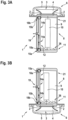
- Figures 3A and 3B jointly also referred to as Figure 3 herein, show an exterior aircraft light 1 according to an exemplary embodiment of the invention.
- Figure 3A depicts the exterior aircraft light 1 in a first orientation, which may be called an upside orientation, and which may correspond to the exterior aircraft light 1 being mounted to the top of the fuselage 130 of an aircraft 100, as it is depicted for the first red-flashing anti-collision beacon light 120a in Figure 2 .
- Figure 3B depicts the exterior aircraft light 1 in a second orientation, which may be called a downside orientation, and which may correspond to the exterior aircraft light 1 being mounted to the bottom of the fuselage 130 of an aircraft 100, as it is depicted for the second red-flashing anti-collision beacon light 120b in Figure 2 .
- red-flashing anti-collision beacon lights are depicted only as examples.
- Figure 3 does not restrict exterior aircraft lights according to exemplary embodiments of the invention to such red-flashing anti-collision beacon lights 120a, 120b.
- the principles of draining water out of the exterior aircraft light as described in the following, may similarly apply to other types of exterior aircraft lights as well.
- the exterior aircraft light 1 depicted in Figure 3 comprises a light output generation unit 3 for generating a light output of the exterior aircraft light 1.
- the light output generation unit 3 comprises at least one light source 2, in particular a plurality of light sources 2, for example a plurality of LEDs, and at least one optical element 4, in particular a reflector 4, which is shaped for forming the light output of the exterior aircraft light 1 from the light that is emitted by the at least one light source 2.
- the light output generation unit 3 may comprise at least one further optical element, such as a lens, a prism, a shutter, and/or a further reflector, in addition to or as an alternative to the reflector 4 depicted in Figure 3 .
- the plurality of light sources 2 and the optical element 4 are enclosed by a light transmissive cover 5, which protects the light output generation unit 3 from adverse external influences, and which allows the light emitted by the plurality of light sources 2 to pass through for providing the light output of the exterior aircraft light 1.
- the exterior aircraft light 1 further comprises a housing 8 defining an interior space 9 that houses power supply electronics 10.
- the power supply electronics 10 are electrically coupled to the plurality of light sources 2 of the light output generation unit 3 for driving and controlling the operation of the plurality of light sources 2.
- the light output generation unit 3 is located in a light head portion 6, which is located outside of the housing 8.
- the light output generation unit 3 may be located inside the housing 8.
- the housing 8 may be a larger housing and may be a joint housing for the light output generation unit 3 and the power supply electronics 10.
- the low portion 11 of the interior space 9 may be on the side of the housing 8 opposite to the light output generation unit 3, as depicted in Figure 3A .
- the low portion 11 of the interior space 9 may on be the side of the housing 8 next to the light output generation unit 3, as its is depicted in Figure 3B .
- the exterior aircraft light 1 is equipped with a draining device 12 for draining the fluid 26, collected within the respective low portion 11 of the interior space 9, irrespective of the orientation in which the exterior aircraft light 1 is mounted to the aircraft 100, i.e. irrespective of whether the exterior aircraft light 1 is mounted to the aircraft 100 in the upside orientation depicted in Figure 3A , or in the downside orientation depicted in Figure 3B .
- Figure 4A shows an enlarged schematic cross-sectional view of a draining device 12 that may be employed in an exterior aircraft light according to an exemplary embodiment of the invention.
- the draining device 12 of Figure 4A may be used as the draining device 12 of the exterior aircraft light 1 of Figure 3 .
- Figure 4B shows a perspective view of the draining device 12 depicted in Figure 4A .
- the draining device 12 comprises a first drainage tube 14a, a second drainage tube 14b, and a fluid discharge port 19.
- the fluid discharge port 19 is in fluid communication with the first drainage tube 14a and the second drainage tube 14b.
- the fluid discharge port 19 is provided at a central portion of the draining device 12 between the first and second drainage tubes 14a, 14b, and the first and second drainage tubes 14a, 14b extend downwards and upwards from said central portion, respectively.
- the first and second drainage tubes 14a, 14b are configured for receiving fluid 26, in particular condensing water, which is to be drained from the interior space 9 of the housing 8, and for discharging said fluid 26 via the fluid discharge port 19 out of the housing 8.
- Figures 3A and 3B illustrate that the first and second drainage tubes 14a, 14b do not simultaneously receive fluid 26 from the interior space 9.
- first and second drainage tubes 14a, 14b are immersed in the fluid 26 collected in the low portion 11 of the interior space 9, whereas the other one of the first and second drainage tubes 14a, 14b extends into an upper portion 21 of the interior space 9, in which no fluid 26 is present.
- the fluid discharge port 19 may comprise a discharge tube 17.
- the discharge tube 17 may in particular be oriented substantially orthogonal to the first drainage tube 14a and/or to the second drainage tube 14b.
- a conduit or hose which is not shown in the figures, may be fluidly coupled to the fluid discharge port 19 and/or to the discharge tube 17.
- Each drainage tube 14a, 14b has a length L a , L b , which is measured from the central portion of the draining device 12 to an outer end of the respective drainage tube 14a, 14b.
- the lengths L a , L b may be in the range of between 20 mm and 120 mm.
- the first and second drainage tubes 14a, 14b may have the same or a comparable length L a , L b . It is also possible that the first and second drainage tubes 14a, 14b have different lengths L a , L b .
- the lengths L a , L b may, inter alia, depend on where a convenient location for the fluid discharge port 19 and/or for the discharge tube 17 is.
- the orientations and lengths L a , L b of the drainage tubes 14a, 14b may in particular be set so that in every orientation, in which the exterior aircraft light 1 may be mounted to the aircraft 100, one of the drainage tubes 14a, 14b extends towards the lowest portion of the interior space 9 for receiving fluid 26, in particular condensing water, collected at said lowest portion of the interior space 9.
- the respective drainage tube 14a, 14b may in particular extend substantially vertically towards the lowest portion of the interior space 9.
- the drainage tubes 14a, 14b may have an inner diameter D 1 in the range of between 2 mm and 15 mm, in particular an inner diameter D 1 in the range of between 4 mm and 10 mm, more particularly an inner diameter D 1 of between 5 mm and 8 mm.
- the fluid discharge port 19 may be fluidly coupled via a duct, conduit or hose, which is not shown in the figures, to the environment outside the aircraft 100.
- a fluid connection between the interior space 9 and the environment outside of the aircraft 100 is provided, with the fluid connection allowing the draining device 12 to discharge the fluid 26 out of the interior space 9 into the environment outside the aircraft 100.
- the discharge tube 17 of the fluid discharge port 19 may also be in direct fluid communication with the environment outside the aircraft 100.
- Each of the first and second drainage tubes 14a, 14b comprises a respective valve mechanism 15a, 15b.
- Enlarged perspective views of the valve mechanisms 15a, 15b are depicted in Figures 5A and 5B , which are jointly also referred to as Figure 5 herein.
- each valve mechanism 15a, 15b is located at an outer end portion of the respective drainage tube 14a, 14b, i.e. at an end portion of the respective drainage tube 14a, 14b that is distal from the central portion of the draining device 12.
- Each valve mechanism 15a, 15b comprises a respective valve portion 16a, 16b and a respective sealing element 18a, 18b, for example a sealing ball, which is movably arranged within the valve portion 16a, 16b of the respective drainage tube 14a, 14b.
- Each sealing element 18a, 18b is in particular movable in the respective valve portion 16a, 16b under the influence of gravity.
- valve portions 16a, 16b may be provided as sections of the respective drainage tubes 14a, 14b.
- the valve portions 16a, 16b may in particular be formed integrally with the drainage tubes 14a, 14b.
- valve portions 16a, 16b may be formed separately from the drainage tubes 14a, 14b and may then be attached to the drainage tubes 14a, 14b.
- valve portions 16a, 16b and the corresponding sealing elements 18a, 18b are shaped and dimensioned such that each sealing element 18a, 18b, driven by gravity, opens the respective drainage tube 14a, 14b, allowing fluid 26 to pass through, when the respective drainage tube 14a, 14b is oriented in a draining orientation.
- the respective drainage tube 14a, 14b extends downwards from the central portion of the draining device 12.
- the first drainage tube 14a is oriented in the draining orientation and extends downwards into a low portion of the interior space 9.
- Figure 5A shows the valve mechanism 15a of said first drainage tube 14a, when oriented in the draining orientation.
- Each valve portion 16a, 16b and the corresponding sealing element 18a, 18b are further shaped and dimensioned such that the sealing element 18a, 18b, driven by gravity, seals the respective drainage tube 14a, 14b in an air-tight manner, when the respective drainage tube 14a, 14b is oriented in a sealing orientation.
- the respective drainage tube 14a, 14b extends upwards from the central portion of the draining device 12.
- the second drainage tube 14b is oriented in the sealing orientation and extends upwards into an upper portion 21 of the interior space 9.
- Figure 5B shows the valve mechanism 15b of said second drainage tube 14b, when oriented in the draining orientation.
- the first drainage tube 14a is oriented in the sealing orientation, in which it extends upwards into the upper portion 21 of the interior space 9, and the second drainage tube 14b is oriented in the draining orientation, in which it extends downwards into the low portion 11 of the interior space 9.
- the drainage tubes 14a, 14b are oriented at an angle ⁇ of 180° with respect to each other and at an angle ⁇ of 90° with respect to the discharge tube 17. This corresponds to the two different orientations in which the exterior aircraft light 1 may be mounted to the aircraft 100, as it is depicted in Figures 2 and 3 .
- the drainage tubes 14a, 14b may be oriented with respect to each other at different angles, i.e. at angles other than 180°.
- the drainage tubes 14a, 14b are also oriented at angles ⁇ that cause the sealing element in the valve portion of the upper drainage tube to seal, driven by gravity, the upper drainage tube in an air-tight manner and that cause the sealing element in the valve portion of the lower drainage tube to open, driven by gravity, the valve mechanism for allowing fluid 26 to pass through.
- the first and second drainage tubes 14a, 14b may, for example, be oriented at an angle ⁇ of between 150° and 180° with respect to each other.
- the first and second drainage tubes 14a, 14b may, in particular, be oriented at an angle ⁇ of between 170° and 180° with respect to each other.
- the drainage tubes 14a, 14b and the discharge tube 17 extend in a common plane, which corresponds to the drawing plane of Figures 3 and 4A .
- Each valve portion 16a, 16b comprises a radially extended portion, with a maximum inner diameter D 2 of the radially extended portion being larger than the inner diameter D 1 of the rest of the respective drainage tube 14a, 14b.
- the valve portion 16a, 16b may have a maximum inner diameter D 2 in the range of between 5 mm and 20 mm, in particular a maximum inner diameter D 2 in the range of between 10 mm and 15 mm.
- each valve portion 16a, 16b comprises an inner conical portion 20a, 20b and an outer conical portion 22a, 22b, respectively.
- the inner conical portion 20a, 20b and the outer conical portion 22a, 22b both have a conical shape.
- Each inner conical portion 20a, 20b has an inner end with a first diameter and an outer end with a second diameter that is larger than the first diameter.
- the inner end of each inner conical portion 20a, 20b faces towards the central portion of the draining device 12, and the outer end of each inner conical portion 20a, 20b faces away from the central portion of the draining device 12.
- each inner conical portion 20a, 20b opens up towards the outer end of the respective drainage tube 14a, 14b, i.e. towards the end of the drainage tube 14a, 14b facing away from the central portion of the draining device 12.
- the smaller diameter at the inner end of the inner conical portion 20a, 20b may in particular be identical with the inner diameter D 1 of the respective drainage tube 14a, 14b.
- Each outer conical portion 22a, 22b has an inner end with a first diameter and an outer end with a second diameter that is smaller than the first diameter.
- the inner end of each outer conical portion 22a, 22b faces towards the central portion of the draining device 12, and the outer end of each outer conical portion 22a, 22b faces away from the central portion of the draining device 12. In other words, the outer conical portions 22a, 22b open up towards the central portion of the draining device 12.
- a central opening 40a, 40b is formed at the outer end of each outer conical portion 22a, 22b, respectively.
- the second diameter at the outer end of the inner conical portion 20a, 20b is identical to the first diameter at the inner end of the outer conical portion 22a, 22b.
- the second diameter at the outer end of the inner conical portion 20a, 20b and the first diameter at the inner end of the outer conical portion 22a, 22b are in particular identical to the maximum inner diameter D 2 of the valve portion 16a, 16b.
- An intermediate portion 24a, 24b having a cylindrical shape, extends between the outer end of the inner conical portion 20a, 20b and the inner end of the outer conical portion 22a, 22b.
- the inner conical portion 20a, 20b, the intermediate portion 24a, 24b, and the outer conical portion 22a, 22b define a sealing element accommodation space for accommodating the sealing element 18a, 18b, with the sealing element 18a, 18b being movable within said sealing element accommodation space.
- the outer conical portion 22a, 22b and the sealing element 18a, 18b are shaped and dimensioned such that the sealing element 18a, 18b, driven by gravity, opens the respective drainage tube 14a, 14b and allows fluid 26 to pass through, when the respective drainage tube 14a, 14b is oriented in the draining orientation, as is the first drainage tube 14a shown in Figures 3A , 4 , and 5A .
- the inner conical portion 20a, 20b and the sealing element 18a, 18b are shaped and dimensioned such that each sealing element 18a, 18b, driven by gravity, seals the respective drainage tube 14a, 14b in an air-tight manner, when the respective drainage tube 14a, 14b is oriented in the sealing orientation, as is the second drainage tube 14b shown in Figures 3A , 4 and 5B .
- the outer conical portions 22a, 22b further provide a retainer structure, preventing the respective sealing element 18a, 18b from dropping out of the respective valve portion 16a, 16b, when the respective drainage tube 14a, 14b is oriented in the draining orientation.
- At least one drainage port 28a, 28b may be formed in each valve portion 16a, 16b, respectively.
- the at least one drainage port 28a, 28b provides for fluid communication between the interior space 9 and the respective drainage tube 14a, 14b, when the respective drainage tube 14a, 14b is oriented in the draining orientation and the corresponding valve mechanism 15a, 15b is open.
- the at least one drainage port 28a, 28b may in particular be formed in the outer conical portion 22a, 22b of the valve portion 16a, 16b.
- two drainage ports 28a, 28b are provided in the form of two slits, which are formed in the outer conical portion 22a, 22b of each valve portion 16a, 16b.
- the two slits are formed at an angular distance of 180° degrees from each other along the circumference of the respective outer conical portion 22a, 22b.
- the slits also allow the outer conical portion 22a, 22b to elastically expand in the radial direction, when the respective sealing element 18a, 18b sits in the central opening 40a, 40b of the respective outer conical portion 22a, 22b.
- FIG. 4B and 5 Although two drainage ports 28a, 28b are depicted in Figures 4B and 5 , more or less than two drainage ports 28a, 28b may be formed in each of the valve portions 16a, 16b, respectively.
- the drainage ports 28a, 28b may include one or more drainage holes.
- Such drainage holes may be formed in the outer conical portions 22a, 22b and/or in the intermediate portions 24a, 24b of the valve portion 16a, 16b, respectively.
- the drainage holes may be provided in addition to or as an alternative to the slits described above.
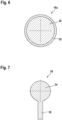
- Figure 6 depicts a cross-sectional view of a sealing element 18a that may be used in exterior aircraft lights according to exemplary embodiments of the invention.
- the sealing element 18a may in particular be used in an exterior aircraft light as depicted in Figures 3 to 5 .
- the sealing element 18a as depicted in Figure 6 , comprises a ball 30, which is covered with a coating 32.
- the ball 30 may be made of metal, of rubber, or of a synthetic material.
- the ball 30 may also be made of a combination of a metal, rubber, and/or a synthetic material.
- the material of the ball 30 may be selected so that the weight of the sealing element 18a is large enough for the sealing element 18a to seal the corresponding drainage tube 14a, 14b in an air-tight manner, when the sealing element 18a is driven by gravity towards the inner conical portion 20a, 20b of the respective valve mechanism 15a, 15b.
- the coating 32 may be an elastic coating 32, in particular a rubber coating 32, for enhancing the sealing capabilities of the sealing element 18a.
- the coating 32 is, however, optional. Thus, it is possible that the sealing element 18a is not coated with a coating 32.
- Figure 7 depicts a cross-sectional view of a sealing element 38 that may be used in exterior aircraft lights according to other exemplary embodiments of the invention.
- the sealing element 38 depicted in Figure 7 , comprises a ball portion 34 and a rod portion 36, extending from the ball portion 34.
- the rod portion 36 may extend from the ball portion 34 in a radial direction, as it is depicted in Figure 7 .
- the rod portion 36 may in particular be configured to extend into the respective drainage tube 14a, 14b, when the sealing element 38 is arranged within the valve portion 16a, 16b of the respective drainage tube 14a, 14b.
- the rod portion 36 may guide the movement of the sealing element 38 between a sealed position and an open position.
- the rod portion 36 may further add weight to the sealing element 38, thus enhancing the sealing capabilities of the sealing element 38.
- the ball portion 34 and the rod portion 36 may comprise the same material, or they may be made from different materials. Such materials may include metal, rubber, and/or synthetic materials.
- the ball portion 34 and the rod portion 36 may be formed integrally. Alternatively, the rod portion 36 and the ball portion 34 may be manufactured separately and may then be joined with each other.
- the rod portion 36 may be glued, soldered or welded to the ball portion 34.
- the ball portion 34 and the rod portion 36 may be provided with matching threads, which allow for screwing the rod portion 36 to the ball portion 34.
- At least one of the ball portion 34 and the rod portion 36 may be at least partially coated with a coating 32, which is not shown in Figure 7 .
- the coating 32 may comprise rubber or another elastic material, in particular an elastic synthetic material.
- a draining device 12 When the aircraft 100, to which an exterior aircraft light 1 according to an exemplary embodiment of the invention is mounted, rises into the air and gains altitude, the air pressure outside the aircraft 100 decreases with increasing height of the aircraft 100. This results in an increasing pressure difference between the higher pressure within the interior space 9 and the decreasing pressure outside the aircraft 100.
- the sealing element 18a within the valve portion 16a of the first drainage tube 14a which in the embodiments depicted in Figures 3A , 4 , and 5A is oriented in the draining orientation and extends downwards from the central portion of the draining device 12 into a low portion of the interior space 9 of the housing 8, drops into the outer conical portion 22a of the valve portion 16a.
- the sealing element 18b within the valve portion 16b of the valve mechanism 15b of the second drainage tube 14b which in the embodiments depicted in Figures 3A , 4 , and 5 is oriented in the sealing orientation and extends upwards from the central portion of the draining device 12 into the upper portion 21 of the interior space 9, drops into the inner conical portion 20b of the valve mechanism 15b at the end of the second drainage tube 14b, sealing the second drainage tube 14b in an air-tight manner.
- the second valve mechanism 15b of the second drainage tube 14b which faces downwards towards the light output generation unit 3 and into the low portion of the interior space 9, opens, allowing the fluid 26 to pass through; and the first valve mechanism 15a of the first drainage tube 14a, which faces upwards away from the light output generation unit 3, is sealed in an air-tight manner.
- the pressure difference between the interior space 9 and the environment of the aircraft 100 may equalize only via the lower valve mechanism 15a, 15b, i.e. via that valve mechanism that may be immersed within the fluid 26.
- the pressure difference between the interior space 9 and the environment of the aircraft 100 drives the fluid 26, collected at the low portion 11 of the interior space 9, via the lower valve mechanism 15a, 15b into the respective lower drainage tube 14a, 14b and via the fluid discharge port 19 out of the aircraft 100.
- the interior space 9, formed within the housing 8 is drained, with said draining being driven by the pressure difference between the interior space 9 and the environment of the aircraft 100.
- An exterior aircraft light 1 ensures that, independently of the orientation in which the exterior aircraft light 1 is mounted to the aircraft 100, the valve mechanism 15a, 15b of the upper drainage tube 14a, 14b, which is not immersed in the fluid 26, is sealed in an air-tight manner, and the valve mechanism 15a, 15b of the lower drainage tube 14a, 14b, which extends into the low portion 11 of the interior space 9, is open, allowing fluid 26 collected in a low portion 11 of the interior space 9 to pass therethrough.
- the draining device 12 of an exterior aircraft light 1 may allow for reliably and effectively draining fluid 26 out of a housing 8 of the exterior aircraft light 1, irrespective of the orientation in which the exterior aircraft light 1 is mounted to the aircraft 100.
Landscapes
- Engineering & Computer Science (AREA)
- General Engineering & Computer Science (AREA)
- Aviation & Aerospace Engineering (AREA)
- Mechanical Engineering (AREA)
- Arrangement Of Elements, Cooling, Sealing, Or The Like Of Lighting Devices (AREA)
Abstract
Description
- The present invention relates to aircraft lighting. In particular, the present invention relates to an exterior aircraft light. The present invention further relates to an aircraft comprising such an exterior aircraft light and to a method of draining a fluid out of an exterior aircraft light.
- Almost all aircraft are equipped with numerous lights, including exterior aircraft lights and interior aircraft lights. In particular, large passenger air planes are provided with a wide variety of exterior and interior aircraft lights.
- Exterior aircraft lights are employed for a wide variety of different purposes, such as for allowing the passengers and/or air crew to view the outside, for passive visibility, for signaling purposes, etc. Examples of such exterior aircraft lights are navigation lights, also referred to as position lights, red-flashing beacon lights, white strobe anti-collision lights, wing scan lights, take-off lights, landing lights, taxi lights, runway turn-off lights, etc.
- An exterior aircraft light may comprise a housing for accommodating electrical and/or optical components. In operation, fluid, for example condensing water, may collect within the housing. Said water may deteriorate the operation of the exterior aircraft light.
- It would therefore be beneficial to provide an exterior aircraft light with a highly effective draining device for draining fluid out of the housing of the exterior aircraft light.
- Exemplary embodiments of the invention include an exterior aircraft light that comprises: a housing defining an interior space; a light output generation unit comprising at least one light source; and power supply electronics, which are coupled to the light output generation unit for driving a light output of the exterior aircraft light. At least one of the light output generation unit and the power supply electronics is arranged within the interior space, defined by the housing.
- The exterior aircraft light further comprises a draining device for draining fluid out of the interior space. The draining device comprises: a first drainage tube for receiving fluid, which is to be drained from the interior space; a second drainage tube for receiving fluid, which is to be drained from the interior space; and a fluid discharge port for discharging fluid out of the housing. The fluid discharge port is in fluid communication with the first drainage tube and with the second drainage tube.
- Although the first and second drainage tubes are both configured / arranged for receiving fluid, which is to be drained, it is to be noted that the first and second drainage tubes are not configured / arranged for receiving the fluid simultaneously. Instead, depending on the spatial orientation of the exterior aircraft light, only one of the first and second drainage tubes will receive fluid. This will be explained in more detail below.
- Each of the first drainage tube and the second drainage tube comprises a valve mechanism for selectively sealing and opening the respective drainage tube with respect to the interior space. Each valve mechanism comprises a valve portion of the respective drainage tube and a sealing element, in particular a sealing ball, arranged in the valve portion of the respective drainage tube. The sealing element is movable in the valve portion under the influence of gravity.
- The valve portion and the sealing element are shaped and dimensioned such that the sealing element, driven by gravity, opens the respective drainage tube and allows fluid to pass through, when the respective drainage tube is oriented in a draining orientation. The valve portion and the sealing element are further shaped and dimensioned such that the sealing element, driven by gravity, seals the respective drainage tube in an air-tight manner, when the respective drainage tube is oriented in a sealing orientation
- Exemplary embodiments of the invention also include a method of draining a fluid out of the interior space of the housing of an exterior aircraft light according to an exemplary embodiment of the invention, with the exterior aircraft light being mounted to an aircraft in a first mounting orientation. When the exterior aircraft light is mounted in the first mounting orientation to the aircraft, the first drainage tube extends in a draining orientation into a low portion of the interior space. The second drainage tube is in its sealing orientation. The method comprises the steps of: when the aircraft is on the ground, with gravity acting upon the sealing elements, opening the valve mechanism of the first drainage tube and closing the valve mechanism of the second drainage tube; taking off the aircraft and gaining altitude; with a pressure difference between the interior space of the housing and an outside environment of the aircraft, driving the fluid through the valve mechanism of the first drainage tube and out of the housing. When the exterior aircraft light is mounted in the second mounting orientation to the aircraft, the second drainage tube extends in a draining orientation into a low portion of the interior space and the first drainage tube is in its sealing orientation. The method steps may then be carried out with the first and second drainage tubes being swapped.
- In a draining device of an exterior aircraft light according to an exemplary embodiment of the invention, the valve mechanism of that drainage tube that extends downwards in the draining orientation is unsealed / opened by gravity, whereas the valve mechanism of the other drainage tube, which is extending upwards in the sealing orientation is sealed by gravity in an air-tight manner. The drainage tube with the unsealed / opened valve mechanism may be immersed in fluid, collected at a low portion of the interior space, and may drain said fluid out of the interior space, while the drainage tube with the sealed valve mechanism extends into an upper portion of the interior space and is not immersed in the fluid.
- In case of a pressure difference between the interior space and the fluid discharge port, the sealed valve mechanism, i.e. the valve mechanism of that drainage tube that extends upwards in the sealing orientation and that is not immersed in the fluid, prevents the pressure from equalizing through the drainage tube that is not immersed in the fluid. In consequence, the pressure difference may equalize only through the other drainage tube, i.e. through that drainage tube that extends downwards in the draining orientation and that is immersed in the fluid. As a result, the pressure difference between the interior space and the fluid discharge port drives the fluid out of the interior space via that drainage tube that extends downwards and that is immersed in the fluid.
- The fluid discharge port may in particular be in fluid communication with the exterior of the aircraft. This may cause a decrease of the pressure within the fluid discharge port and the drainage tubes of the draining device, when the aircraft is gaining altitude. Thus, the rise of the aircraft after take-off may generate a pressure difference between the interior space and the fluid discharge port that acts as a driving force for draining the fluid out of the interior space.
- The draining device of an exterior aircraft light according to an exemplary embodiment of the invention may effectively and reliably drain fluid, such as condensing water, out of the interior space of the housing of the exterior aircraft light, without the need for providing a mechanical pumping mechanism. The draining device may be an entirely passive draining device. The actuation of the draining device may take place via the pressure conditions present during the flight of the aircraft. The draining device of an exterior aircraft light according to an exemplary embodiment of the invention may comprise only two movable parts, namely the movable sealing elements. It may therefore be easy to produce and it may not need extensive maintenance. The draining device of an exterior aircraft light according to an exemplary embodiment of the invention is very reliable, as it is operable without being connected to a power source.
- In an embodiment, the draining orientation is a downward orientation, in which the respective drainage tube extends from the fluid discharge port into a low portion of the interior space. Such an orientation of the drainage tube allows for draining fluid that is collected in a low portion of the interior space, in particular at the bottom of the interior space.
- In an embodiment, the sealing orientation is an upward orientation, in which the respective drainage tube extends from the fluid discharge port into an upper portion of the interior space. A drainage tube that extends from the fluid discharge port into an upper portion of the interior space is not immersed within fluid collecting in a low portion of the interior space. This drainage tube is sealed in an air-tight manner, in order to prevent air from leaving the interior space via the drainage tube that extends into an upper portion of the interior space, without driving fluid out of the interior space.
- In an embodiment, the first drainage tube and the second drainage tube are oriented at an angle of between 150° and 180° with respect to each other. The first drainage tube and the second drainage tube may in particular oriented at an angle of between 170° and 180° with respect to each other. An angle of between 150° and 180°, in particular an angle of between 170° and 180°, between the two drainage tubes allows for the sealing elements to be moved simultaneously and highly reliably by gravity into their respective positions for opening the valve mechanism of the drainage tube that is oriented in the draining orientation and for sealing the valve mechanism of the drainage tube that is oriented in the sealing orientation.
- In an embodiment, for at least one the first drainage tube and the second drainage tube, in particular for both of the first drainage tube and the second drainage tube, the valve portion comprises a radially extended portion with a diameter of the radially extended portion being larger than a diameter of the rest of the respective drainage tube. A radially extended portion having a larger diameter than the respective drainage tube may provide a sealing element accommodation space for accommodating the sealing element. In said sealing element accommodation space, the sealing element may be movable, in particular by gravity, between an open position, in which it opens the valve mechanism of the drainage tube when oriented in the draining orientation, and a sealing position, in which it seals the valve mechanism of the drainage tube when oriented in the sealing orientation.
- In an embodiment, the valve portions of all drainage tubes of the draining device comprise a respective radially extended portion.
- In an embodiment, for at least one the first drainage tube and the second drainage tube, in particular for both of the first drainage tube and the second drainage tube, the valve portion comprises an inner conical portion having a conical shape. In an embodiment, the valve portions of all drainage tubes of the draining device comprise a respective inner conical portion. The inner conical portion may in particular be shaped and dimensioned for accommodating the sealing element in such a manner that it seals the drainage tube in an air-tight manner, when the respective drainage tube is oriented in the sealing orientation. The inner conical portion may act as an effective and easily implementable means for achieving the sealing of the valve mechanism in question.
- In an embodiment, the wall of the conical portion is inclined at an angle of between 35° and 45° with respect to the longitudinal extension of the drainage tube. An angle in the range of between 35° and 45° has been found to be well suited for allowing the sealing element to reliably seal the drainage tube in an air-tight manner, when the respective drainage tube is oriented in the sealing orientation.
- In an embodiment, for at least one the first drainage tube and the second drainage tube, in particular for both of the first drainage tube and the second drainage tube, the valve portion comprises an outer conical portion having a conical shape. In an embodiment, the valve portions of all drainage tubes of the draining device comprise a respective outer conical portion. The outer conical portion may have a central opening or may be closed towards the end of the respective drainage tube. The outer conical portion may be dimensioned such that the outer conical portion acts as a retainer, preventing the sealing element from dropping out of the valve portion, when the respective drainage tube is oriented in the draining orientation. The outer conical portion may act as an effective and easily implementable means for achieving a retaining of the sealing element in the valve mechanism in question.
- In an embodiment, the inner conical portion and the outer conical portion of the respective valve portion face each other. In particular, the inner conical portion and the outer conical portion may be funnel-like structures, whose more extended ends face each other. The inner conical portion and the outer conical portion may form the sealing element accommodation space, wherein the sealing element is movable within the sealing element accommodation space, formed between the inner and outer conical portions.
- In an embodiment, an intermediate portion, in particular a cylindrical intermediate portion, extends between the inner conical portion and the outer conical portion. An intermediate portion, extending between the inner conical portion and the outer conical portion, may enlarge the sealing element accommodation space, allowing more movement of the sealing element within the sealing element accommodation space. Hence, more flexibility regarding the design of further opening and sealing features, such as the drainage port(s) described below, may be achieved.
- In an embodiment, at least one drainage port is formed in the valve portion. The at least one drainage port may in particular be formed in an outer conical portion and/or in an intermediate portion of the valve portion. The at least one drainage port may provide for fluid communication between the interior space of the housing and the respective drainage tube, when the respective drainage tube is oriented in the draining orientation.
- In an embodiment, a plurality of drainage ports are formed along the circumference of the valve portion. The plurality of drainage ports may in particular be formed at equal angular distances with respect to each other along the circumference of the valve portion.
- In an embodiment, the at least one drainage port in provided in the form of at least one longitudinal slit. The longitudinal slit(s) may in particular be formed in an outer conical portion of the valve portion. It / they may extend into the intermediate portion of the valve portion. Such longitudinal slit(s) may provide for fluid communication between the interior space and the respective drainage tube, when the respective drainage tube is oriented in the draining orientation. The longitudinal slit(s) may provide for effective and easily implementable means for achieving fluid communication between the interior space and the respective drainage tube. The longitudinal slit(s) may further allow the outer conical portion to elastically expand in the radial direction, when the sealing element is arranged within the outer conical portion.
- The at least one longitudinal slit may or may not extend from an outer end of the drainage tube. The at least one longitudinal slit may in particular extend from a central opening that is formed in an outer conical portion of the valve portion.
- In an embodiment, the at least one drainage port includes at least one drainage hole. Such drainage hole(s) may be formed in the outer conical portion and/or in the intermediate portion of the valve portion.
- In an embodiment, for at least one the first drainage tube and the second drainage tube, in particular for both of the first drainage tube and the second drainage tube, the drainage tube has an inner diameter in the range of between 2 mm and 10 mm, in particular an inner diameter in the range of between 4 mm and 6 mm, more particularly an inner diameter of about 5 mm.
- In an embodiment, for at least one the first drainage tube and the second drainage tube, in particular for both of the first drainage tube and the second drainage tube, the radially extended valve portion has a maximum inner diameter in the range of between 5 mm and 20 mm, in particular a maximum inner diameter in the range of between 10 mm and 15 mm.
- In an embodiment, for at least one the first drainage tube and the second drainage tube, in particular for both of the first drainage tube and the second drainage tube, the sealing element of the valve mechanism has an outer diameter in the range of between 4 mm and 15 mm, in particular an outer diameter in the range of between 6 mm and 10 mm, more particularly an outer diameter of about 8 mm.
- In an embodiment, for at least one the first drainage tube and the second drainage tube, in particular for both of the first drainage tube and the second drainage tube, the sealing element of the valve mechanism has a weight in the range of between 3 g and 15 g, in particular a weight in the range of between 8 g and 12 g, more particularly a weight of about 10 g.
- Such dimensions / properties of the drainage tubes and the sealing elements have been found to be well suited for reliably sealing a drainage tube in an air-tight manner, when the drainage tube is oriented in the sealing orientation, and for allowing a sufficient amount of fluid to pass through a drainage tube that is oriented in the draining orientation.
- In an embodiment, the sealing element comprises a metal ball. A metal ball has been found to provide a suitable sealing element, which reliably seals the drainage tube in an air-tight manner, when the drainage tube is arranged in the sealing orientation. Also, a metal ball can be reliably produced with suitable accuracy for achieving a reliable sealing of the valve mechanism.
- In an embodiment, the sealing element comprises a metal ball that is covered with an elastic coating, in particular with a rubber coating. An elastic coating, such as a rubber coating, may enhance the sealing capabilities of the sealing element.
- In an embodiment, the sealing element comprises a ball portion and a rod portion, extending from the ball portion. The rod portion may in particular extend from the ball portion in a radial direction.
- In an embodiment, the rod portion extends into a respective drainage tube, when the sealing element is arranged within the valve portion of the respective drainage tube. In such a configuration, the rod portion may guide the movement of the sealing element between a sealing position and an open position. Also, the rod portion may provide convenient and effective means of increasing the weight of the sealing element, thus contributing to an effective and reliable sealing of the valve mechanism, when the drainage tube is in the sealing orientation.
- In an embodiment, the ball portion and the rod portion of the sealing element are formed integrally. Such an integrally formed sealing element may be manufactured in a cost-efficient manner in a single manufacturing process.
- In an embodiment, the rod portion and the ball portion are manufactured separately and are then joined with each other. The rod portion may, for example, be glued, soldered or welded to the ball portion.
- In an embodiment, the ball portion and the rod portion are provided with matching threads, in order to allow for screwing the rod portion to the ball portion for securely joining the rod portion and the ball portion.
- The ball portion and the rod portion may comprise materials that may include metal, rubber and/or synthetic materials.
- In an embodiment, the ball portion and the rod portion comprise the same material. In another embodiment, the ball portion and the rod portion are made from different materials.
- In an embodiment, at least one of the ball portion and the rod portion is at least partially coated with a coating for enhancing the sealing capabilities of the sealing element. The coating may comprise rubber or another elastic material, in particular an elastic synthetic material.
- In an embodiment, the valve mechanism is arranged at an outer end portion of the respective drainage tube.
- In an embodiment, the fluid discharge port comprises a discharge tube. The discharge tube may in particular be oriented substantially orthogonal to the first drainage tube and/or to the second drainage tube. The discharge tube may be in fluid communication with the outer environment of the aircraft. The discharge tube may be in fluid communication with a conduit or hose that is in turn in fluid communication with the outer environment of the aircraft.
- In an embodiment, the discharge tube, the first drainage tube and the second drainage tube extend in a common plane.
- In an alternative embodiment, the discharge tube, the first drainage tube and the second drainage tube do not extend in a common plane.
- The geometries and the spatial orientations of the discharge tube, the first drainage tube and the second drainage tube may in particular depend on the potential mounting orientations in which the exterior aircraft light may be mounted to the aircraft.
- In an embodiment, the exterior aircraft light is mountable to an aircraft in a first mounting orientation and in a second mounting orientation. When the exterior aircraft light is in the first mounting orientation, the first drainage tube extends into a first portion of the interior space for receiving fluid from the first portion of the interior space, with the first portion being a low portion of the interior space. In this scenario, the first drainage tube is in its draining orientation and the second drainage tube is in its sealing orientation. When the exterior aircraft light is in the second mounting orientation, the second drainage tube extends into a second portion of the interior space for receiving fluid from the second portion of the interior space, with the second portion being a low portion of the interior space. In this scenario, the second drainage tube is in its draining orientation and the first drainage tube is in its sealing orientation.
- For exterior aircraft lights according to exemplary embodiments of the invention, the same type of exterior aircraft light may be mounted to an aircraft in at least two different mounting orientations. The particular mounting orientation may be chosen depending on the desired position of the exterior aircraft light in the aircraft frame of reference and/or on the particular type of aircraft. As a result, the total number of different exterior aircraft lights that are required for equipping an aircraft / an aircraft fleet with a complete set of exterior aircraft lights may be reduced. In consequence, the efforts and costs for equipping an aircraft / an aircraft fleet with a complete set of exterior aircraft lights may be reduced as well.
- In an embodiment, the exterior aircraft light is an aircraft headlight, for example an aircraft landing light or an aircraft take-off light or an aircraft taxi light or an aircraft runway turn-off light, or a multi-functional aircraft headlight, which combines the functionalities of any two or any three or all of an aircraft landing light, an aircraft take-off light, an aircraft taxi light, and an aircraft runway turn-off light. An aircraft headlight according to an exemplary embodiment of the invention may be configured such that it can be mounted to an aircraft running gear in at least two different orientations.
- In an embodiment, the exterior aircraft light is an aircraft navigation light, in particular a wing-tip-mounted aircraft navigation light. An aircraft navigation light according to an exemplary embodiment of the invention may be configured such that it can be mounted to a left wing tip or to a right wing tip of an aircraft. The orientation of the aircraft navigation light, when mounted to the left wing tip of the aircraft, may be different from the orientation of the aircraft navigation light, when mounted to the right wing tip of the aircraft. In particular, the two mounting orientations may differ by 180°.
- In an embodiment, the exterior aircraft is a red-flashing aircraft beacon light, in particular a fuselage-mounted red-flashing aircraft beacon light. A red-flashing aircraft beacon light according to an exemplary embodiment of the invention may be configured such that it can be mounted to a top portion or to a bottom portion of an aircraft fuselage. The two mounting orientations may differ by 180°.
- In an embodiment, the light output generation unit and the power supply electronics are both arranged within the housing. Such an embodiment may provide for a compact exterior aircraft light in which many or all important components of the exterior aircraft light are arranged in a single housing.
- In an embodiment, the power supply electronics are arranged in the housing and the light output generation unit is arranged in a separate light head portion of the exterior aircraft light, which is arranged outside of the housing. Such an embodiment may provide for an exterior aircraft light in which the light head portion may be positioned and installed independently of the housing. This may provide a high degree of flexibility regarding the installation of the exterior aircraft light.
- Exemplary embodiments of the invention further include an aircraft, such as an airplane or a helicopter, that is equipped with at least one exterior aircraft light according to an exemplary embodiment of the invention. The additional features, modifications and effects, as described above with respect to an exterior aircraft light in accordance with exemplary embodiments of the invention, apply to the aircraft in an analogous manner.
- Further exemplary embodiments of the invention are described below with respect to the accompanying drawings, wherein:
-
Figure 1A shows a schematic top view of an aircraft according to an exemplary embodiment of the invention, which is equipped with a variety of exterior aircraft lights; -
Figure 1B shows a schematic front view of the aircraft shown inFigure 1A ; -
Figure 2 shows a schematic cross-sectional view of the fuselage of an aircraft that is equipped with two exterior aircraft lights according to exemplary embodiments of the invention; -
Figure 3A shows an exterior aircraft light according to an exemplary embodiment of the invention in a first orientation; -
Figure 3B shows the exterior aircraft light ofFigure 3A in a second orientation; -
Figure 4A shows an enlarged schematic cross-sectional view of a draining device that may be used in exterior aircraft lights according to exemplary embodiments of the invention; -
Figure 4B shows a perspective view of the draining device depicted inFigure 4A ; -
Figures 5A shows an enlarged perspective view of a valve mechanism of the draining device, as depicted inFigures 4A and 4B , in a draining orientation. -
Figures 5B shows an enlarged perspective view of a valve mechanism of the draining device, as depicted inFigures 4A and 4B , in a sealing orientation. -
Figure 6 depicts a cross-sectional view of a sealing element that may be used in exterior aircraft lights according to exemplary embodiments of the invention. -
Figure 7 depicts a cross-sectional view of another sealing element that may be used in exterior aircraft lights according to exemplary embodiments of the invention. -
Figures 1A and1B , jointly also referred to asFigure 1 herein, show anaircraft 100, in particular an airplane, comprising afuselage 130, which houses acockpit 202 and apassenger cabin 204, and twowings 140, extending from thefuselage 130. Twohorizontal stabilizers 170 and avertical stabilizer 180 extend from a rear portion of thefuselage 130. Anengine 150 is mounted to each of thewings 140, respectively. Theaircraft 100 is shown in a top view inFigure 1A and shown in a front view inFigure 1B . - The
aircraft 100 ofFigure 1 is equipped with a wide variety of exterior lights. In particular, theaircraft 100 is equipped with threenavigation lights 106, twologo lights 108, twowing scan lights 110, twoengine scan lights 112, two runway turn-offlights 114, two cargo loading lights 116, three whiteanti-collision strobe lights 118, two red-flashinganti-collision beacon lights landing light 122, a take-off light 124 and ataxi light 126. It is pointed out that these kinds of lights and their numbers are exemplary only and that theaircraft 100 may be equipped with additional lights that are not shown. - The three
navigation lights 106 are positioned in the left andright wing tips 142 as well as at thetail 160 of theaircraft 100. In normal flight conditions, each one of thenavigation lights 106 emits light in one of the colors green, red and white, thus indicating to the aircraft environment if they are looking at the port side, starboard side or tail side of the aircraft. Thenavigation lights 106 are normally on during all phases of the flight and in all flight conditions. - The logo lights 108 are directed to the
vertical stabilizer 180 of theaircraft 100 and are provided for illuminating the same, in particular for illuminating the logo commonly provided on thevertical stabilizer 180. The logo lights 108 are normally switched on for the entire duration of the flight during night flights. It is also possible that the logo lights are only used during taxiing on the airport and are normally switched off during the flight. - The
wing scan lights 110 and theengine scan lights 112 are positioned on the left and right sides of thefuselage 130, in front of theroots 144 of thewings 140 of theaircraft 100. Thewing scan lights 110 and theengine scan lights 112 are normally off during the flight and may be switched on periodically or upon reasonable cause by the pilots or by the aircrew, in order to check thewings 140 and theengines 150 of theaircraft 100. - The runway turn-off
lights 114 are positioned in theroots 144 of thewings 140. The runway turn-offlights 114 are directed forwards and are normally switched off during the flight and switched on during taxiing, at least at night. - The
cargo loading lights 116 are positioned on the left and right sides of thefuselage 130, behind thewings 140 and in front of the tail structure of theaircraft 100. They are normally switched off during the flight of theaircraft 100. - The white
anti-collision strobe lights 118 are positioned in the left andright wing tips 142 as well as at thetail 160 of theaircraft 100. The whiteanti-collision strobe lights 118 emit respective sequences of white light flashes during normal operation of theaircraft 100. It is also possible that the whiteanti-collision strobe lights 118 are only operated during night and in bad weather conditions. - A first red-flashing anti-collision beacon light 120a is positioned on the top of the
fuselage 130 of theaircraft 100, and a second red-flashing anti-collision beacon light 120b is positioned at the bottom of thefuselage 130 of theaircraft 100. The second red-flashing anti-collision beacon light 120b, disposed on the bottom of thefuselage 130, is shown in phantom inFigure 1A . - The first and second red-flashing
anti-collision beacon lights aircraft 100. The red-flashinganti-collision beacon lights - In the embodiment depicted in
Figure 1 , the runway turn-offlights 114 are located in thewings 140, in particular in theroots 144 of thewings 140, and thelanding light 122, the take-off light 124 and thetaxi light 126 are mounted to thefront gear 135 of theaircraft 100. Thefront gear 135 is stored within thefuselage 130 of theaircraft 100 during flight, and it is deployed during landing, taxiing and take off. - In alternative embodiments, which are not explicitly shown in the figures, the runway turn-off
lights 114 may be mounted to thefront gear 135 and/or at least one of thelanding light 122, the take-off light 124 and thetaxi light 126 may be installed in thewings 140, in particular in theroots 144 of thewings 140, of theaircraft 100. - The
aircraft 100 may also comprise one or more multi-functional lights, which combine(s) the functionalities of at least two of a landing light, a take-off light, a taxi light, and a runway turn-off light. - Since the
landing light 122, the take-off light 124, and thetaxi light 126 are arranged on the bottom of theaircraft 100, they are also depicted in phantom inFigure 1A . - Each of these exterior aircraft lights may be an exterior aircraft light according to an exemplary embodiment of the invention. In particular, those ones of the depicted exterior aircraft lights where a single type / design of exterior aircraft light may be mounted to the aircraft in different orientations and/or at different mounting positions may largely benefit from the implementation in accordance with exemplary embodiments of the invention. Exemplary embodiments of the invention may for example be provided for the
landing light 122, the take-off light 124, thetaxi light 126, the runway turn-offlights 114, thenavigation lights 106 at the left and right wing tips, and the red-flashinganti-collision beacon lights aircraft 100 is an aircraft in accordance with an exemplary embodiment of the invention. - At least some of the exterior aircraft lights depicted in
Figure 1 may be mounted in different orientations to theaircraft 100. In other words, the same type of exterior aircraft light may be mounted in at least two different orientations and/or at different positions of theaircraft 100. - As an example,
Figure 2 shows a schematic cross-sectional view of thefuselage 130 of anaircraft 100 that is equipped with two red-flashinganti-collision beacon lights - A first red-flashing anti-collision beacon light 120a is mounted to a top portion of the
fuselage 130, and a second red-flashing anti-collision beacon light 120b is mounted to a bottom portion of thefuselage 130. - The first red-flashing anti-collision beacon light 120a and the second red-flashing anti-collision beacon light 120b may have the same structure / design, i.e. the first red-flashing anti-collision beacon light 120a and the second red-flashing anti-collision beacon light 120b may be identical apart from being mounted to the
fuselage 130 of theaircraft 100 in an upside-down orientation with respect to each other. -
Fluid 26, which may in particular be condensing water admixed with dirt, may collect at the bottom of thefuselage 130. This fluid may penetrate into the second red-flashing anti-collision beacon light 120b. As mentioned, it is desirable to drain this fluid 26 out of the second red-flashing anti-collision beacon light 120b. - Although two red-flashing
anti-collision beacon lights Figure 2 , the problem offluid 26 collecting within the exterior aircraft light may similarly apply to other types of exterior aircraft lights as well. - Such exterior aircraft lights may in particular include aircraft headlights, for example aircraft landing lights and aircraft take-off lights, aircraft taxi lights, an aircraft runway turn-off lights, and multi-functional aircraft headlights, which combine the functionalities of at least two of an aircraft landing light, an aircraft take-off light, an aircraft taxi light, and an aircraft runway turn-off light, as they are depicted in
Figure 1 . - Exterior aircraft lights according to exemplary embodiments of the invention may further include aircraft navigation lights, in particular wing-tip-mounted aircraft navigation lights, as they are depicted in
Figure 1 . -
Figures 3A and 3B , jointly also referred to asFigure 3 herein, show anexterior aircraft light 1 according to an exemplary embodiment of the invention. -
Figure 3A depicts theexterior aircraft light 1 in a first orientation, which may be called an upside orientation, and which may correspond to theexterior aircraft light 1 being mounted to the top of thefuselage 130 of anaircraft 100, as it is depicted for the first red-flashing anti-collision beacon light 120a inFigure 2 . -
Figure 3B depicts theexterior aircraft light 1 in a second orientation, which may be called a downside orientation, and which may correspond to theexterior aircraft light 1 being mounted to the bottom of thefuselage 130 of anaircraft 100, as it is depicted for the second red-flashing anti-collision beacon light 120b inFigure 2 . - In
Figure 3 , the red-flashing anti-collision beacon lights are depicted only as examples.Figure 3 does not restrict exterior aircraft lights according to exemplary embodiments of the invention to such red-flashinganti-collision beacon lights - The
exterior aircraft light 1 depicted inFigure 3 comprises a lightoutput generation unit 3 for generating a light output of theexterior aircraft light 1. The lightoutput generation unit 3 comprises at least onelight source 2, in particular a plurality oflight sources 2, for example a plurality of LEDs, and at least oneoptical element 4, in particular areflector 4, which is shaped for forming the light output of the exterior aircraft light 1 from the light that is emitted by the at least onelight source 2. - Although not explicitly shown in
Figure 3 , the lightoutput generation unit 3 may comprise at least one further optical element, such as a lens, a prism, a shutter, and/or a further reflector, in addition to or as an alternative to thereflector 4 depicted inFigure 3 . - The plurality of
light sources 2 and theoptical element 4 are enclosed by alight transmissive cover 5, which protects the lightoutput generation unit 3 from adverse external influences, and which allows the light emitted by the plurality oflight sources 2 to pass through for providing the light output of theexterior aircraft light 1. - The
exterior aircraft light 1 further comprises ahousing 8 defining aninterior space 9 that housespower supply electronics 10. Thepower supply electronics 10 are electrically coupled to the plurality oflight sources 2 of the lightoutput generation unit 3 for driving and controlling the operation of the plurality oflight sources 2. - In the embodiment depicted in
Figure 3 , the lightoutput generation unit 3 is located in alight head portion 6, which is located outside of thehousing 8. In further embodiments, which are not explicitly shown in the figures, the lightoutput generation unit 3 may be located inside thehousing 8. In other words, thehousing 8 may be a larger housing and may be a joint housing for the lightoutput generation unit 3 and thepower supply electronics 10. - As depicted in
Figure 3 ,fluid 26, which may in particular be condensing water, potentially admixed with dirt, exhaust residues, atmospheric particles, etc., may collect in alow portion 11 of theinterior space 9. Depending on the orientation, in which theexterior aircraft light 1 is mounted to theaircraft 100, thelow portion 11 of theinterior space 9 may be on the side of thehousing 8 opposite to the lightoutput generation unit 3, as depicted inFigure 3A . Alternatively, thelow portion 11 of theinterior space 9 may on be the side of thehousing 8 next to the lightoutput generation unit 3, as its is depicted inFigure 3B . - The
exterior aircraft light 1 is equipped with a drainingdevice 12 for draining the fluid 26, collected within the respectivelow portion 11 of theinterior space 9, irrespective of the orientation in which theexterior aircraft light 1 is mounted to theaircraft 100, i.e. irrespective of whether theexterior aircraft light 1 is mounted to theaircraft 100 in the upside orientation depicted inFigure 3A , or in the downside orientation depicted inFigure 3B . -
Figure 4A shows an enlarged schematic cross-sectional view of a drainingdevice 12 that may be employed in an exterior aircraft light according to an exemplary embodiment of the invention. In particular, the drainingdevice 12 ofFigure 4A may be used as the drainingdevice 12 of theexterior aircraft light 1 ofFigure 3 .Figure 4B shows a perspective view of the drainingdevice 12 depicted inFigure 4A . - The draining
device 12 comprises afirst drainage tube 14a, asecond drainage tube 14b, and afluid discharge port 19. Thefluid discharge port 19 is in fluid communication with thefirst drainage tube 14a and thesecond drainage tube 14b. - In the exemplary embodiment depicted in
Figures 3 and4 , thefluid discharge port 19 is provided at a central portion of the drainingdevice 12 between the first andsecond drainage tubes second drainage tubes - The first and
second drainage tubes fluid 26, in particular condensing water, which is to be drained from theinterior space 9 of thehousing 8, and for discharging saidfluid 26 via thefluid discharge port 19 out of thehousing 8. -
Figures 3A and 3B illustrate that the first andsecond drainage tubes interior space 9. Depending on the spatial orientation of theexterior aircraft light 1, only one of the first andsecond drainage tubes low portion 11 of theinterior space 9, whereas the other one of the first andsecond drainage tubes upper portion 21 of theinterior space 9, in which nofluid 26 is present. - The
fluid discharge port 19 may comprise adischarge tube 17. Thedischarge tube 17 may in particular be oriented substantially orthogonal to thefirst drainage tube 14a and/or to thesecond drainage tube 14b. A conduit or hose, which is not shown in the figures, may be fluidly coupled to thefluid discharge port 19 and/or to thedischarge tube 17. - Each
drainage tube device 12 to an outer end of therespective drainage tube - The first and
second drainage tubes second drainage tubes fluid discharge port 19 and/or for thedischarge tube 17 is. - The orientations and lengths La, Lb of the
drainage tubes exterior aircraft light 1 may be mounted to theaircraft 100, one of thedrainage tubes interior space 9 for receivingfluid 26, in particular condensing water, collected at said lowest portion of theinterior space 9. Therespective drainage tube interior space 9. - The
drainage tubes - The
fluid discharge port 19 may be fluidly coupled via a duct, conduit or hose, which is not shown in the figures, to the environment outside theaircraft 100. A fluid connection between theinterior space 9 and the environment outside of theaircraft 100 is provided, with the fluid connection allowing the drainingdevice 12 to discharge the fluid 26 out of theinterior space 9 into the environment outside theaircraft 100. Thedischarge tube 17 of thefluid discharge port 19 may also be in direct fluid communication with the environment outside theaircraft 100. - Each of the first and
second drainage tubes respective valve mechanism valve mechanisms Figures 5A and 5B , which are jointly also referred to asFigure 5 herein. - In the exemplary embodiment depicted in
Figures 3 to 5 , eachvalve mechanism respective drainage tube respective drainage tube device 12. - Each
valve mechanism respective valve portion respective sealing element valve portion respective drainage tube element respective valve portion - The
valve portions respective drainage tubes valve portions drainage tubes - Alternatively, the
valve portions drainage tubes drainage tubes - The
valve portions corresponding sealing elements element respective drainage tube fluid 26 to pass through, when therespective drainage tube respective drainage tube device 12. - In the orientation of the draining
device 12 depicted inFigures 3A and4 , thefirst drainage tube 14a is oriented in the draining orientation and extends downwards into a low portion of theinterior space 9.Figure 5A shows thevalve mechanism 15a of saidfirst drainage tube 14a, when oriented in the draining orientation. - Each
valve portion corresponding sealing element element respective drainage tube respective drainage tube respective drainage tube device 12. - In the orientation of the draining
device 12 depicted inFigures 3A and4 , thesecond drainage tube 14b is oriented in the sealing orientation and extends upwards into anupper portion 21 of theinterior space 9.Figure 5B shows thevalve mechanism 15b of saidsecond drainage tube 14b, when oriented in the draining orientation. - In the alternative orientation of the draining
device 12 depicted inFigure 3B , thefirst drainage tube 14a is oriented in the sealing orientation, in which it extends upwards into theupper portion 21 of theinterior space 9, and thesecond drainage tube 14b is oriented in the draining orientation, in which it extends downwards into thelow portion 11 of theinterior space 9. - In the embodiment depicted in
Figures 3 and4 , thedrainage tubes discharge tube 17. This corresponds to the two different orientations in which theexterior aircraft light 1 may be mounted to theaircraft 100, as it is depicted inFigures 2 and3 . - In further embodiments, which are not explicitly shown in the figures, the
drainage tubes drainage tubes fluid 26 to pass through. - The first and
second drainage tubes second drainage tubes - In the exemplary embodiment depicted in
Figures 3 and4 , thedrainage tubes discharge tube 17 extend in a common plane, which corresponds to the drawing plane ofFigures 3 and4A . Different geometries of the drainingdevice 12, in particular geometries in which thedrainage tubes discharge tube 17 do not extend in a common plane, are possible as well. - Each
valve portion respective drainage tube - The
valve portion - In the embodiment depicted in
Figures 3 to 5 , eachvalve portion conical portion conical portion conical portion conical portion - Each inner
conical portion conical portion device 12, and the outer end of each innerconical portion device 12. In other words, each innerconical portion respective drainage tube drainage tube device 12. - The smaller diameter at the inner end of the inner
conical portion respective drainage tube - Each outer
conical portion conical portion device 12, and the outer end of each outerconical portion device 12. In other words, the outerconical portions device 12. - A
central opening conical portion - In the embodiment depicted in
Figures 3 to 5 , the second diameter at the outer end of the innerconical portion conical portion conical portion conical portion valve portion - An
intermediate portion conical portion conical portion - In combination, the inner
conical portion intermediate portion conical portion sealing element element - The outer
conical portion element element respective drainage tube respective drainage tube first drainage tube 14a shown inFigures 3A ,4 , and5A . - The inner
conical portion element element respective drainage tube respective drainage tube second drainage tube 14b shown inFigures 3A ,4 and5B . - The outer
conical portions respective sealing element respective valve portion respective drainage tube - At least one
drainage port valve portion drainage port interior space 9 and therespective drainage tube respective drainage tube corresponding valve mechanism - The at least one
drainage port conical portion valve portion - In the embodiment depicted in
Figures 4 and5 , twodrainage ports conical portion valve portion conical portion conical portion respective sealing element central opening conical portion - Although two
drainage ports Figures 4B and5 , more or less than twodrainage ports valve portions - In further embodiments, which are not explicitly shown in the figures, the
drainage ports conical portions intermediate portions valve portion -
Figure 6 depicts a cross-sectional view of a sealingelement 18a that may be used in exterior aircraft lights according to exemplary embodiments of the invention. The sealingelement 18a may in particular be used in an exterior aircraft light as depicted inFigures 3 to 5 . The sealingelement 18a, as depicted inFigure 6 , comprises aball 30, which is covered with acoating 32. - The
ball 30 may be made of metal, of rubber, or of a synthetic material. Theball 30 may also be made of a combination of a metal, rubber, and/or a synthetic material. - The material of the
ball 30 may be selected so that the weight of the sealingelement 18a is large enough for the sealingelement 18a to seal thecorresponding drainage tube element 18a is driven by gravity towards the innerconical portion respective valve mechanism - The
coating 32 may be anelastic coating 32, in particular arubber coating 32, for enhancing the sealing capabilities of the sealingelement 18a. Thecoating 32 is, however, optional. Thus, it is possible that the sealingelement 18a is not coated with acoating 32. -
Figure 7 depicts a cross-sectional view of a sealingelement 38 that may be used in exterior aircraft lights according to other exemplary embodiments of the invention. The sealingelement 38, depicted inFigure 7 , comprises aball portion 34 and arod portion 36, extending from theball portion 34. - The
rod portion 36 may extend from theball portion 34 in a radial direction, as it is depicted inFigure 7 . Therod portion 36 may in particular be configured to extend into therespective drainage tube element 38 is arranged within thevalve portion respective drainage tube rod portion 36 may guide the movement of the sealingelement 38 between a sealed position and an open position. Therod portion 36 may further add weight to the sealingelement 38, thus enhancing the sealing capabilities of the sealingelement 38. - The
ball portion 34 and therod portion 36 may comprise the same material, or they may be made from different materials. Such materials may include metal, rubber, and/or synthetic materials. - The
ball portion 34 and therod portion 36 may be formed integrally. Alternatively, therod portion 36 and theball portion 34 may be manufactured separately and may then be joined with each other. - The
rod portion 36 may be glued, soldered or welded to theball portion 34. Alternatively, theball portion 34 and therod portion 36 may be provided with matching threads, which allow for screwing therod portion 36 to theball portion 34. - Similar to the embodiment depicted in
Figure 6 , at least one of theball portion 34 and therod portion 36 may be at least partially coated with acoating 32, which is not shown inFigure 7 . Thecoating 32 may comprise rubber or another elastic material, in particular an elastic synthetic material. - In the following, the operation of a draining
device 12 according to an exemplary embodiment of the invention is described:
When theaircraft 100, to which anexterior aircraft light 1 according to an exemplary embodiment of the invention is mounted, rises into the air and gains altitude, the air pressure outside theaircraft 100 decreases with increasing height of theaircraft 100. This results in an increasing pressure difference between the higher pressure within theinterior space 9 and the decreasing pressure outside theaircraft 100. - Due to gravity acting upon the
sealing elements valve portions valve mechanisms drainage tubes element 18a within thevalve portion 16a of thefirst drainage tube 14a, which in the embodiments depicted inFigures 3A ,4 , and5A is oriented in the draining orientation and extends downwards from the central portion of the drainingdevice 12 into a low portion of theinterior space 9 of thehousing 8, drops into the outerconical portion 22a of thevalve portion 16a. This opens thevalve mechanism 15a, allowingfluid 26, which is collected within theinterior space 9 of thehousing 8, to pass through thevalve mechanism 15a and to enter into thefirst drainage tube 14a. - The sealing
element 18b within thevalve portion 16b of thevalve mechanism 15b of thesecond drainage tube 14b, which in the embodiments depicted inFigures 3A ,4 , and5 is oriented in the sealing orientation and extends upwards from the central portion of the drainingdevice 12 into theupper portion 21 of theinterior space 9, drops into the innerconical portion 20b of thevalve mechanism 15b at the end of thesecond drainage tube 14b, sealing thesecond drainage tube 14b in an air-tight manner. - In the alternative orientation of the
exterior aircraft light 1 depicted inFigure 3B , thesecond valve mechanism 15b of thesecond drainage tube 14b, which faces downwards towards the lightoutput generation unit 3 and into the low portion of theinterior space 9, opens, allowing the fluid 26 to pass through; and thefirst valve mechanism 15a of thefirst drainage tube 14a, which faces upwards away from the lightoutput generation unit 3, is sealed in an air-tight manner. - In an
exterior aircraft light 1 according to an exemplary embodiment of the invention, since the upper one of thevalve mechanisms interior space 9 and the environment of theaircraft 100 may equalize only via thelower valve mechanism fluid 26. - In consequence, the pressure difference between the
interior space 9 and the environment of theaircraft 100 drives the fluid 26, collected at thelow portion 11 of theinterior space 9, via thelower valve mechanism lower drainage tube fluid discharge port 19 out of theaircraft 100. As a result, theinterior space 9, formed within thehousing 8, is drained, with said draining being driven by the pressure difference between theinterior space 9 and the environment of theaircraft 100. - Sealing the
upper drainage tube drainage tube upper drainage tube interior space 9. - An
exterior aircraft light 1 according to an exemplary embodiment of the present invention ensures that, independently of the orientation in which theexterior aircraft light 1 is mounted to theaircraft 100, thevalve mechanism upper drainage tube valve mechanism lower drainage tube low portion 11 of theinterior space 9, is open, allowingfluid 26 collected in alow portion 11 of theinterior space 9 to pass therethrough. - In consequence, the draining
device 12 of anexterior aircraft light 1 according to an exemplary embodiment of the invention may allow for reliably and effectively drainingfluid 26 out of ahousing 8 of theexterior aircraft light 1, irrespective of the orientation in which theexterior aircraft light 1 is mounted to theaircraft 100. - While the invention has been described with reference to exemplary embodiments, it will be understood by those skilled in the art that various changes may be made and equivalents may be substituted for elements thereof without departing from the scope of the invention. In addition, many modifications may be made to adapt a particular situation or material to the teachings of the invention without departing from the essential scope thereof. Therefore, it is intended that the invention not be limited to the particular embodiment disclosed, but that the invention will include all embodiments falling within the scope of the appended claims.
Claims (15)
- Exterior aircraft light (1), comprising:a housing (8) defining an interior space (9);a light output generation unit (3) comprising at least one light source (2);power supply electronics (10), coupled to the light output generation unit (3) for driving a light output of the exterior aircraft light (1);
wherein at least one of the light output generation unit (3) and the power supply electronics (10) is arranged within the interior space (9); anda draining device (12) for draining the interior space (9),the draining device (12) comprising:a first drainage tube (14a) for receiving fluid (26), which is to be drained from the interior space (9);a second drainage tube (14b) for receiving fluid (26), which is to be drained from the interior space (9); anda fluid discharge port (19) for discharging fluid (26) out of the housing (8), wherein the fluid discharge port (19) is in fluid communication with the first drainage tube (14a) and with the second drainage tube (14b);wherein each of the first drainage tube (14a) and the second drainage tube (14b) comprises a valve mechanism (15a, 15b) for selectively sealing and opening the respective drainage tube (14a, 14b) with respect to the interior space (9), each valve mechanism (15a, 15b) comprising:a valve portion (16a, 16b) of the respective drainage tube (14a, 14b); anda sealing element (18a, 18b), in particular a sealing ball, arranged in the valve portion (16a, 16b) of the respective drainage tube (14a, 14b),wherein the sealing element (18a, 18b) is movable in the valve portion (16a, 16b) under the influence of gravity;wherein the valve portion (16a, 16b) and the sealing element (18a, 18b) are shaped and dimensioned such that the sealing element (18a, 18b), driven by gravity, opens the respective drainage tube (14a, 14b), when the respective drainage tube (14a, 14b) is oriented in a draining orientation; andwherein the valve portion (16a, 16b) and the sealing element (18a, 18b) are shaped and dimensioned such that the sealing element (18a, 18b), driven by gravity, seals the respective drainage tube (14a, 14b) in an air-tight manner, when the respective drainage tube (14a, 14b) is oriented in a sealing orientation. - Exterior aircraft light (1) according to claim 1,wherein the draining orientation is a downward orientation, in which the respective drainage tube (14a, 14b) extends from the fluid discharge port (19) into a low portion (11) of the interior space (9); andwherein the sealing orientation is an upward orientation, in which the respective drainage tube (14a, 14b) extends from the fluid discharge port (19) into an upper portion (21) of the interior space (9);wherein the first drainage tube (14a) and the second drainage tube (14b) are in particular oriented at an angle (α) of between 150° and 180° with respect to each other, wherein the first drainage tube (14a) and the second drainage tube (14b) are more in particular oriented at an angle (α) of between 170° and 180° with respect to each other.
- Exterior aircraft light (1) according to any of the preceding claims, wherein the valve portion (16a, 16b) comprises a radially extended portion, with a diameter of the radially extended portion being larger than a diameter of the rest of the respective drainage tube (14a, 14b).
- Exterior aircraft light (1) according to any of the preceding claims, wherein the valve portion (16a, 16b) comprises an inner conical portion (20a, 20b), wherein the inner conical portion is in particular dimensioned for accommodating the sealing element (18a, 18b) in an air-tight manner, when the respective drainage tube (14a, 14b) is oriented in the sealing orientation.
- Exterior aircraft light (1) according to claim 4, wherein the valve portion (16a, 16b) further comprises an outer conical portion (22a, 22b), wherein the inner conical portion (20a, 20b) and the outer conical portion (22a, 22b) face each other, forming a sealing element accommodation space for accommodating the sealing element (18a, 18b), with the sealing element (18a, 18b) being movable between the inner conical portion (20a, 20b) and the outer conical portion (22a, 22b).
- Exterior aircraft light (1) according to any of the preceding claims, wherein at least one drainage port (28a, 28b), in particular at least one slit, is formed in the valve portion (16a, 16b), in particular in an outer conical portion (22a, 22b) of the valve portion (16a, 16b), wherein the at least one drainage port (28a, 28b) provides for fluid communication between the interior space (9) and the respective drainage tube (14a, 14b), when the respective drainage tube (14a, 14b) is oriented in the draining orientation.
- Exterior aircraft light (1) according to any of the preceding claims,wherein the first and second drainage tubes (14a, 14b) have an inner diameter (D) in the range of between 2 mm and 10 mm, in particular an inner diameter (D) in the range of between 4 mm and 6 mm, more particularly an inner diameter (D) of about 5 mm; and/orwherein the sealing element (18a, 18b) has an outer diameter (da) in the range of between 4 mm and 15 mm, in particular an outer diameter (da) in the range of between 6 mm and 10 mm, more particularly an outer diameter (da) of about 8 mm; and/orwherein the sealing element (18a, 18b) has a weight in the range of between 3 g and 15 g, in particular a weight in the range of between 8 g and 12 g, more particularly a weight of about 10 g.
- Exterior aircraft light (1) according to any of the preceding claims,wherein the sealing element (18a, 18b) comprises a metal ball (30), wherein the sealing element in particular comprises a metal ball (30) covered with a coating (32), in particular with an elastic coating (32), such as a rubber coating (32); and/orwherein the sealing element (18a, 18b) comprises a ball portion (34) and a rod portion (36), extending from the ball portion (34), wherein the rod portion (36) in particular extends into the respective drainage tube (14a, 14b).
- Exterior aircraft light (1) according to any of the preceding claims, wherein the valve mechanism (15a, 15b) is arranged at an end portion of the respective drainage tube (14a, 14b).
- Exterior aircraft light (1) according to any of the preceding claims, wherein the fluid discharge port (19) comprises a discharge tube (17), wherein the discharge tube (17) is in particular oriented substantially orthogonal to the first drainage tube (14a) and/or to the second drainage tube (14b).
- Exterior aircraft light (1) according to any of the preceding claims,wherein the exterior aircraft light (1) is mountable to an aircraft (100) in a first mounting orientation and in a second mounting orientation;wherein the first drainage tube (14a) extends into a first portion of the interior space (9) for receiving fluid (26) from the first portion of the interior space (9),wherein the first portion is a low portion (11) of the interior space (9), when the exterior aircraft light (1) is in the first mounting orientation; andwherein the second drainage tube (14b) extends into a second portion of the interior space (9) for receiving fluid (26) from the second portion of the interior space (9), wherein the second portion is a low portion (11) of the interior space (9), when the exterior aircraft light (1) is in the second mounting orientation.
- Exterior aircraft light (1) according to any of the preceding claims,wherein the light output generation unit (3) and the power supply electronics (10) are arranged in the housing (8); orwherein the power supply electronics (10) are arranged in the housing (8) and wherein the light output generation unit (3) is arranged in a separate light head portion (6) of the exterior aircraft light (1), which is arranged outside of the housing (8).
- Exterior aircraft light (1) according to any of the preceding claims,wherein the exterior aircraft light (1) is an aircraft headlight, such as an aircraft landing light (122) or an aircraft take-off light (124) or an aircraft taxi light (126) or an aircraft runway turn-off light (114) or a multi-functional aircraft headlight, which combines the functionalities of at least two of an aircraft landing light (122), an aircraft take-off light (124), an aircraft taxi light (126), and an aircraft runway turn-off light (114); orwherein the exterior aircraft light (1) is an aircraft navigation light (106), in particular a wing-tip-mounted aircraft navigation light (106); orwherein the exterior aircraft light (1) is a red-flashing aircraft beacon light (120a, 120b), in particular a fuselage-mounted red-flashing aircraft beacon light (120a, 120b).
- Aircraft (100), such as an airplane or a helicopter, comprising at least one exterior aircraft light (1) according to any of the preceding claims.
- Method of draining a fluid (26) out of the interior space (9) of the housing (8) of an exterior aircraft light (1) according to any of claims 1 to 13, with the exterior aircraft light (1) being mounted to an aircraft (100) in a first mounting orientation, wherein the first drainage tube (14a) extends in its draining orientation into a low portion (11) of the interior space (9), when the exterior aircraft light (1) is mounted in its first mounting orientation to the aircraft (100), and wherein the method comprises the steps of:when the aircraft (100) is on the ground, with gravity acting upon the sealing elements, opening the valve mechanism (15a) of the first drainage tube (14a) and closing the valve mechanism (15b) of the second drainage tube (14b);taking off the aircraft (100) and gaining altitude;with a pressure difference between the interior space (9) of the housing (8) and an outside environment of the aircraft (100), driving the fluid (26) through the valve mechanism (15a, 15b) of the first drainage tube (14a) and out of the housing (8).
Priority Applications (2)
| Application Number | Priority Date | Filing Date | Title |
|---|---|---|---|
| EP23178965.2A EP4477559B1 (en) | 2023-06-13 | 2023-06-13 | Exterior aircraft light, aircraft comprising an exterior aircraft light and method of draining a fluid out of an exterior aircraft light |
| US18/674,645 US12305828B2 (en) | 2023-06-13 | 2024-05-24 | Exterior aircraft light, aircraft comprising an exterior aircraft light and method of draining a fluid out of an exterior aircraft light |
Applications Claiming Priority (1)
| Application Number | Priority Date | Filing Date | Title |
|---|---|---|---|
| EP23178965.2A EP4477559B1 (en) | 2023-06-13 | 2023-06-13 | Exterior aircraft light, aircraft comprising an exterior aircraft light and method of draining a fluid out of an exterior aircraft light |
Publications (2)
| Publication Number | Publication Date |
|---|---|
| EP4477559A1 true EP4477559A1 (en) | 2024-12-18 |
| EP4477559B1 EP4477559B1 (en) | 2026-01-21 |
Family
ID=86764763
Family Applications (1)
| Application Number | Title | Priority Date | Filing Date |
|---|---|---|---|
| EP23178965.2A Active EP4477559B1 (en) | 2023-06-13 | 2023-06-13 | Exterior aircraft light, aircraft comprising an exterior aircraft light and method of draining a fluid out of an exterior aircraft light |
Country Status (2)
| Country | Link |
|---|---|
| US (1) | US12305828B2 (en) |
| EP (1) | EP4477559B1 (en) |
Citations (5)
| Publication number | Priority date | Publication date | Assignee | Title |
|---|---|---|---|---|
| US6278382B1 (en) * | 1998-11-06 | 2001-08-21 | Demarco Ralph Anthony | Recognition/anti-collision light for aircraft |
| US20100027281A1 (en) * | 2008-07-31 | 2010-02-04 | Waters Stanley E | LED Anti-Collision Light for Commercial Aircraft |
| CA3004732A1 (en) * | 2017-05-19 | 2018-11-19 | Goodrich Lighting Systems Gmbh | Drain valve, exterior aircraft light unit and power supply box |
| EP3626629A1 (en) * | 2018-09-21 | 2020-03-25 | Goodrich Lighting Systems GmbH | Exterior aircraft light and aircraft comprising the same |
| US10843813B2 (en) * | 2018-08-01 | 2020-11-24 | Koito Manufacturing Co., Ltd. | Lamp unit |
Family Cites Families (9)
| Publication number | Priority date | Publication date | Assignee | Title |
|---|---|---|---|---|
| US1270961A (en) * | 1915-08-21 | 1918-07-02 | Samuel Lippert | Valve. |
| US1594168A (en) | 1919-05-01 | 1926-07-27 | Goff Frank | Drain valve |
| US5251111A (en) * | 1992-09-28 | 1993-10-05 | General Motors Corporation | Composite headlamp vent device |
| JP3235039B2 (en) * | 1993-08-06 | 2001-12-04 | 日産自動車株式会社 | Lamp structure |
| DE19649864A1 (en) | 1996-12-02 | 1998-06-04 | Graaff Vertriebs Gmbh | Automatic drainage device for freight containers or other cargo-receiving rooms |
| US8931932B2 (en) * | 2010-04-16 | 2015-01-13 | G.H.L. International, Inc. | Moisture release valve for an outdoor light fixture |
| KR101338556B1 (en) * | 2012-08-09 | 2013-12-06 | 현대모비스 주식회사 | Moisture generation for preventing structure of vehicle head lamp |
| EP4197916B1 (en) * | 2021-12-20 | 2025-06-18 | Goodrich Corporation | Magnetically controlled fluid drain valve for aircraft exterior light unit |
| CN115597031A (en) * | 2022-07-20 | 2023-01-13 | 潘启友(Cn) | An adjustable LED far and near light module |
-
2023
- 2023-06-13 EP EP23178965.2A patent/EP4477559B1/en active Active
-
2024
- 2024-05-24 US US18/674,645 patent/US12305828B2/en active Active
Patent Citations (5)
| Publication number | Priority date | Publication date | Assignee | Title |
|---|---|---|---|---|
| US6278382B1 (en) * | 1998-11-06 | 2001-08-21 | Demarco Ralph Anthony | Recognition/anti-collision light for aircraft |
| US20100027281A1 (en) * | 2008-07-31 | 2010-02-04 | Waters Stanley E | LED Anti-Collision Light for Commercial Aircraft |
| CA3004732A1 (en) * | 2017-05-19 | 2018-11-19 | Goodrich Lighting Systems Gmbh | Drain valve, exterior aircraft light unit and power supply box |
| US10843813B2 (en) * | 2018-08-01 | 2020-11-24 | Koito Manufacturing Co., Ltd. | Lamp unit |
| EP3626629A1 (en) * | 2018-09-21 | 2020-03-25 | Goodrich Lighting Systems GmbH | Exterior aircraft light and aircraft comprising the same |
Also Published As
| Publication number | Publication date |
|---|---|
| US12305828B2 (en) | 2025-05-20 |
| US20240418340A1 (en) | 2024-12-19 |
| EP4477559B1 (en) | 2026-01-21 |
Similar Documents
| Publication | Publication Date | Title |
|---|---|---|
| CN107757936B (en) | Exterior aircraft light unit and method of alerting ground personnel | |
| US8337059B2 (en) | Control-surface-mounted landing and taxi lights | |
| CN111824435B (en) | Aircraft beacon light and aircraft including an aircraft beacon light | |
| US10710742B2 (en) | Exterior aircraft light and aircraft comprising the same | |
| EP3572334B1 (en) | Multi-mode aircraft navigation light and aircraft comprising the same | |
| US20160046390A1 (en) | Aircraft beacon light unit and set of aircraft beacon light units | |
| US11565828B2 (en) | Exterior aircraft light cover, exterior aircraft light comprising the same, and method of upgrading or maintaining an exterior aircraft light | |
| US20200094988A1 (en) | Exterior aircraft light, aircraft wing comprising the same, and method of operating an exterior aircraft light | |
| US12305828B2 (en) | Exterior aircraft light, aircraft comprising an exterior aircraft light and method of draining a fluid out of an exterior aircraft light | |
| US12043412B2 (en) | Aircraft beacon light, aircraft comprising an aircraft beacon light, and method of determining a health status of an aircraft beacon light | |
| US12435857B2 (en) | Exterior aircraft light, aircraft comprising an exterior aircraft light and method of draining a fluid out of an exterior aircraft light | |
| US10815004B2 (en) | Lens structure for a light unit, light unit, and aircraft comprising such light unit | |
| EP4620832A1 (en) | Exterior aircraft light, aircraft comprising the same, and method for checking the operation of an exterior aircraft light | |
| EP4491520A1 (en) | Exterior lighting water removal valve | |
| EP4491521A1 (en) | Aircraft light, aircraft comprising an aircraft light and method of manufacturing an aircraft light | |
| US12325534B2 (en) | Aircraft light, aircraft comprising an aircraft light, and method of manufacturing an aircraft light | |
| US12365483B2 (en) | Aircraft light, aircraft comprising an aircraft light, and method of assembling an aircraft light | |
| US12607322B2 (en) | Aircraft light, aircraft comprising an aircraft light, and method of manufacturing an aircraft light | |
| US20240369202A1 (en) | Exterior aircraft light, aircraft comprising an exterior aircraft light, and method of manufacturing an exterior aircraft light | |
| EP4339105A1 (en) | Aircraft beacon light, aircraft with an aircraft beacon light and method of operating an aircraft beacon light | |
| BR102019026033B1 (en) | AIRCRAFT BEACON LIGHT, AND, AIRCRAFT |
Legal Events
| Date | Code | Title | Description |
|---|---|---|---|
| PUAI | Public reference made under article 153(3) epc to a published international application that has entered the european phase |
Free format text: ORIGINAL CODE: 0009012 |
|
| STAA | Information on the status of an ep patent application or granted ep patent |
Free format text: STATUS: THE APPLICATION HAS BEEN PUBLISHED |
|
| AK | Designated contracting states |
Kind code of ref document: A1 Designated state(s): AL AT BE BG CH CY CZ DE DK EE ES FI FR GB GR HR HU IE IS IT LI LT LU LV MC ME MK MT NL NO PL PT RO RS SE SI SK SM TR |
|
| STAA | Information on the status of an ep patent application or granted ep patent |
Free format text: STATUS: REQUEST FOR EXAMINATION WAS MADE |
|
| 17P | Request for examination filed |
Effective date: 20250616 |
|
| GRAP | Despatch of communication of intention to grant a patent |
Free format text: ORIGINAL CODE: EPIDOSNIGR1 |
|
| STAA | Information on the status of an ep patent application or granted ep patent |
Free format text: STATUS: GRANT OF PATENT IS INTENDED |
|
| RIC1 | Information provided on ipc code assigned before grant |
Ipc: B64D 47/04 20060101AFI20250723BHEP Ipc: B64D 47/06 20060101ALI20250723BHEP Ipc: F16K 15/04 20060101ALI20250723BHEP Ipc: F21S 45/30 20180101ALI20250723BHEP Ipc: F21W 107/30 20180101ALN20250723BHEP |
|
| INTG | Intention to grant announced |
Effective date: 20250814 |
|
| GRAS | Grant fee paid |
Free format text: ORIGINAL CODE: EPIDOSNIGR3 |
|
| GRAA | (expected) grant |
Free format text: ORIGINAL CODE: 0009210 |
|
| STAA | Information on the status of an ep patent application or granted ep patent |
Free format text: STATUS: THE PATENT HAS BEEN GRANTED |
|
| AK | Designated contracting states |
Kind code of ref document: B1 Designated state(s): AL AT BE BG CH CY CZ DE DK EE ES FI FR GB GR HR HU IE IS IT LI LT LU LV MC ME MK MT NL NO PL PT RO RS SE SI SK SM TR |
|
| REG | Reference to a national code |
Ref country code: CH Ref legal event code: F10 Free format text: ST27 STATUS EVENT CODE: U-0-0-F10-F00 (AS PROVIDED BY THE NATIONAL OFFICE) Effective date: 20260121 |
|
| REG | Reference to a national code |
Ref country code: DE Ref legal event code: R096 Ref document number: 602023010911 Country of ref document: DE |
|
| REG | Reference to a national code |
Ref country code: IE Ref legal event code: FG4D |
|
| REG | Reference to a national code |
Ref country code: NL Ref legal event code: MP Effective date: 20260121 |
|
| PG25 | Lapsed in a contracting state [announced via postgrant information from national office to epo] |
Ref country code: NL Free format text: LAPSE BECAUSE OF FAILURE TO SUBMIT A TRANSLATION OF THE DESCRIPTION OR TO PAY THE FEE WITHIN THE PRESCRIBED TIME-LIMIT Effective date: 20260121 |
|
| REG | Reference to a national code |
Ref country code: AT Ref legal event code: MK05 Ref document number: 1878607 Country of ref document: AT Kind code of ref document: T Effective date: 20260121 |
|
| PG25 | Lapsed in a contracting state [announced via postgrant information from national office to epo] |
Ref country code: RS Free format text: LAPSE BECAUSE OF FAILURE TO SUBMIT A TRANSLATION OF THE DESCRIPTION OR TO PAY THE FEE WITHIN THE PRESCRIBED TIME-LIMIT Effective date: 20260421 |
|
| PG25 | Lapsed in a contracting state [announced via postgrant information from national office to epo] |
Ref country code: ES Free format text: LAPSE BECAUSE OF FAILURE TO SUBMIT A TRANSLATION OF THE DESCRIPTION OR TO PAY THE FEE WITHIN THE PRESCRIBED TIME-LIMIT Effective date: 20260121 |
|
| PG25 | Lapsed in a contracting state [announced via postgrant information from national office to epo] |
Ref country code: PL Free format text: LAPSE BECAUSE OF FAILURE TO SUBMIT A TRANSLATION OF THE DESCRIPTION OR TO PAY THE FEE WITHIN THE PRESCRIBED TIME-LIMIT Effective date: 20260121 |
|
| PG25 | Lapsed in a contracting state [announced via postgrant information from national office to epo] |
Ref country code: GR Free format text: LAPSE BECAUSE OF FAILURE TO SUBMIT A TRANSLATION OF THE DESCRIPTION OR TO PAY THE FEE WITHIN THE PRESCRIBED TIME-LIMIT Effective date: 20260422 |
|
| REG | Reference to a national code |
Ref country code: LT Ref legal event code: MG9D |
|
| PG25 | Lapsed in a contracting state [announced via postgrant information from national office to epo] |
Ref country code: LT Free format text: LAPSE BECAUSE OF FAILURE TO SUBMIT A TRANSLATION OF THE DESCRIPTION OR TO PAY THE FEE WITHIN THE PRESCRIBED TIME-LIMIT Effective date: 20260121 |
|
| PGFP | Annual fee paid to national office [announced via postgrant information from national office to epo] |
Ref country code: DE Payment date: 20260520 Year of fee payment: 4 |
|
| PG25 | Lapsed in a contracting state [announced via postgrant information from national office to epo] |
Ref country code: NO Free format text: LAPSE BECAUSE OF FAILURE TO SUBMIT A TRANSLATION OF THE DESCRIPTION OR TO PAY THE FEE WITHIN THE PRESCRIBED TIME-LIMIT Effective date: 20260421 |
|
| PG25 | Lapsed in a contracting state [announced via postgrant information from national office to epo] |
Ref country code: SE Free format text: LAPSE BECAUSE OF FAILURE TO SUBMIT A TRANSLATION OF THE DESCRIPTION OR TO PAY THE FEE WITHIN THE PRESCRIBED TIME-LIMIT Effective date: 20260121 Ref country code: AT Free format text: LAPSE BECAUSE OF FAILURE TO SUBMIT A TRANSLATION OF THE DESCRIPTION OR TO PAY THE FEE WITHIN THE PRESCRIBED TIME-LIMIT Effective date: 20260121 Ref country code: FI Free format text: LAPSE BECAUSE OF FAILURE TO SUBMIT A TRANSLATION OF THE DESCRIPTION OR TO PAY THE FEE WITHIN THE PRESCRIBED TIME-LIMIT Effective date: 20260121 |
|
| PG25 | Lapsed in a contracting state [announced via postgrant information from national office to epo] |
Ref country code: HR Free format text: LAPSE BECAUSE OF FAILURE TO SUBMIT A TRANSLATION OF THE DESCRIPTION OR TO PAY THE FEE WITHIN THE PRESCRIBED TIME-LIMIT Effective date: 20260121 |
|
| PG25 | Lapsed in a contracting state [announced via postgrant information from national office to epo] |
Ref country code: IS Free format text: LAPSE BECAUSE OF FAILURE TO SUBMIT A TRANSLATION OF THE DESCRIPTION OR TO PAY THE FEE WITHIN THE PRESCRIBED TIME-LIMIT Effective date: 20260521 Ref country code: PT Free format text: LAPSE BECAUSE OF FAILURE TO SUBMIT A TRANSLATION OF THE DESCRIPTION OR TO PAY THE FEE WITHIN THE PRESCRIBED TIME-LIMIT Effective date: 20260521 |
|
| PGFP | Annual fee paid to national office [announced via postgrant information from national office to epo] |
Ref country code: FR Payment date: 20260521 Year of fee payment: 4 |
|
| PG25 | Lapsed in a contracting state [announced via postgrant information from national office to epo] |
Ref country code: LV Free format text: LAPSE BECAUSE OF FAILURE TO SUBMIT A TRANSLATION OF THE DESCRIPTION OR TO PAY THE FEE WITHIN THE PRESCRIBED TIME-LIMIT Effective date: 20260121 |
|
| PG25 | Lapsed in a contracting state [announced via postgrant information from national office to epo] |
Ref country code: BG Free format text: LAPSE BECAUSE OF FAILURE TO SUBMIT A TRANSLATION OF THE DESCRIPTION OR TO PAY THE FEE WITHIN THE PRESCRIBED TIME-LIMIT Effective date: 20260121 |