EP4477536A1 - Moveable wing tip actuation system - Google Patents
Moveable wing tip actuation system Download PDFInfo
- Publication number
- EP4477536A1 EP4477536A1 EP24178828.0A EP24178828A EP4477536A1 EP 4477536 A1 EP4477536 A1 EP 4477536A1 EP 24178828 A EP24178828 A EP 24178828A EP 4477536 A1 EP4477536 A1 EP 4477536A1
- Authority
- EP
- European Patent Office
- Prior art keywords
- wing
- tip device
- hinge
- mass
- wing tip
- Prior art date
- Legal status (The legal status is an assumption and is not a legal conclusion. Google has not performed a legal analysis and makes no representation as to the accuracy of the status listed.)
- Pending
Links
Images






Classifications
-
- B—PERFORMING OPERATIONS; TRANSPORTING
- B64—AIRCRAFT; AVIATION; COSMONAUTICS
- B64C—AEROPLANES; HELICOPTERS
- B64C13/00—Control systems or transmitting systems for actuating flying-control surfaces, lift-increasing flaps, air brakes, or spoilers
- B64C13/02—Initiating means
- B64C13/16—Initiating means actuated automatically, e.g. responsive to gust detectors
-
- B—PERFORMING OPERATIONS; TRANSPORTING
- B64—AIRCRAFT; AVIATION; COSMONAUTICS
- B64C—AEROPLANES; HELICOPTERS
- B64C3/00—Wings
- B64C3/38—Adjustment of complete wings or parts thereof
- B64C3/42—Adjusting about chordwise axes
-
- B—PERFORMING OPERATIONS; TRANSPORTING
- B64—AIRCRAFT; AVIATION; COSMONAUTICS
- B64C—AEROPLANES; HELICOPTERS
- B64C23/00—Influencing air flow over aircraft surfaces, not otherwise provided for
- B64C23/06—Influencing air flow over aircraft surfaces, not otherwise provided for by generating vortices
- B64C23/065—Influencing air flow over aircraft surfaces, not otherwise provided for by generating vortices at the wing tips
- B64C23/069—Influencing air flow over aircraft surfaces, not otherwise provided for by generating vortices at the wing tips using one or more wing tip airfoil devices, e.g. winglets, splines, wing tip fences or raked wingtips
- B64C23/072—Influencing air flow over aircraft surfaces, not otherwise provided for by generating vortices at the wing tips using one or more wing tip airfoil devices, e.g. winglets, splines, wing tip fences or raked wingtips the wing tip airfoil devices being moveable in their entirety
-
- B—PERFORMING OPERATIONS; TRANSPORTING
- B64—AIRCRAFT; AVIATION; COSMONAUTICS
- B64C—AEROPLANES; HELICOPTERS
- B64C13/00—Control systems or transmitting systems for actuating flying-control surfaces, lift-increasing flaps, air brakes, or spoilers
- B64C13/24—Transmitting means
- B64C13/26—Transmitting means without power amplification or where power amplification is irrelevant
- B64C13/28—Transmitting means without power amplification or where power amplification is irrelevant mechanical
- B64C13/34—Transmitting means without power amplification or where power amplification is irrelevant mechanical using toothed gearing
-
- B—PERFORMING OPERATIONS; TRANSPORTING
- B64—AIRCRAFT; AVIATION; COSMONAUTICS
- B64C—AEROPLANES; HELICOPTERS
- B64C13/00—Control systems or transmitting systems for actuating flying-control surfaces, lift-increasing flaps, air brakes, or spoilers
- B64C13/24—Transmitting means
- B64C13/38—Transmitting means with power amplification
- B64C13/50—Transmitting means with power amplification using electrical energy
-
- B—PERFORMING OPERATIONS; TRANSPORTING
- B64—AIRCRAFT; AVIATION; COSMONAUTICS
- B64C—AEROPLANES; HELICOPTERS
- B64C23/00—Influencing air flow over aircraft surfaces, not otherwise provided for
-
- B—PERFORMING OPERATIONS; TRANSPORTING
- B64—AIRCRAFT; AVIATION; COSMONAUTICS
- B64C—AEROPLANES; HELICOPTERS
- B64C23/00—Influencing air flow over aircraft surfaces, not otherwise provided for
- B64C23/06—Influencing air flow over aircraft surfaces, not otherwise provided for by generating vortices
- B64C23/065—Influencing air flow over aircraft surfaces, not otherwise provided for by generating vortices at the wing tips
-
- B—PERFORMING OPERATIONS; TRANSPORTING
- B64—AIRCRAFT; AVIATION; COSMONAUTICS
- B64C—AEROPLANES; HELICOPTERS
- B64C3/00—Wings
- B64C3/38—Adjustment of complete wings or parts thereof
-
- B—PERFORMING OPERATIONS; TRANSPORTING
- B64—AIRCRAFT; AVIATION; COSMONAUTICS
- B64C—AEROPLANES; HELICOPTERS
- B64C3/00—Wings
- B64C3/38—Adjustment of complete wings or parts thereof
- B64C3/385—Variable incidence wings
-
- B—PERFORMING OPERATIONS; TRANSPORTING
- B64—AIRCRAFT; AVIATION; COSMONAUTICS
- B64C—AEROPLANES; HELICOPTERS
- B64C3/00—Wings
- B64C3/38—Adjustment of complete wings or parts thereof
- B64C3/54—Varying in area
- B64C3/546—Varying in area by foldable elements
-
- B—PERFORMING OPERATIONS; TRANSPORTING
- B64—AIRCRAFT; AVIATION; COSMONAUTICS
- B64C—AEROPLANES; HELICOPTERS
- B64C3/00—Wings
- B64C3/38—Adjustment of complete wings or parts thereof
- B64C3/56—Folding or collapsing to reduce overall dimensions of aircraft
-
- Y—GENERAL TAGGING OF NEW TECHNOLOGICAL DEVELOPMENTS; GENERAL TAGGING OF CROSS-SECTIONAL TECHNOLOGIES SPANNING OVER SEVERAL SECTIONS OF THE IPC; TECHNICAL SUBJECTS COVERED BY FORMER USPC CROSS-REFERENCE ART COLLECTIONS [XRACs] AND DIGESTS
- Y02—TECHNOLOGIES OR APPLICATIONS FOR MITIGATION OR ADAPTATION AGAINST CLIMATE CHANGE
- Y02T—CLIMATE CHANGE MITIGATION TECHNOLOGIES RELATED TO TRANSPORTATION
- Y02T50/00—Aeronautics or air transport
- Y02T50/10—Drag reduction
Definitions
- the present invention relates to an aircraft wing with a moveable wing tip device.
- a moveable wing tip device during flight is known, e.g. from WO2017118832 .
- This document teaches an aircraft wing having a fixed wing with a wing tip device moveably mounted at the tip thereof, wherein the fixed wing has an upper surface and a lower surface, and the wing tip device has an upper surface and a lower surface, and the wing tip device is operable between: (i) a flight configuration for use during flight, in which configuration the upper and lower surfaces of the wing tip device are continuations of the upper and lower surfaces of the fixed wing; and (ii) a load alleviating configuration for load alleviation during flight, in which configuration the wing tip device is moved relative to the fixed wing such that at least one of the upper and lower surfaces of the wing tip device is moved away from the respective surface of the fixed wing, and the load on the wing is reduced; wherein the aircraft comprises a restraining assembly operable between a restraining mode in which the wing tip device is held in the flight configuration using
- the wing tip device may be entirely passively actuated to the load-alleviating configuration once the restraining assembly is in releasing mode. It may be moved under the action of aerodynamic forces urging the wing tip device towards the load-alleviating configuration. Having the restraining assembly in combination with this hinged wing tip device may be referred to as a "semi-aeroelastic" arrangement.
- the wing tip device may be rotatably mounted on a hinge at the tip of the wing, such that it may rotate, about the hinge, between the flight and load alleviating configurations.
- the wing tip device may also be moveable about the same hinge to a ground configuration for use during ground-based operations, in which ground configuration the wing tip device is moved away from the flight configuration such that the span of the aircraft wing is reduced.
- An actuation system may be arranged to move the wing tip device between the flight configuration and the ground configuration.
- the actuation system may also be arranged to move the wing tip device from the load alleviating configuration back to the flight configuration.
- a first aspect of the invention provides an aircraft wing comprises a fixed wing with a tip, and a wing tip device rotatably mounted on a hinge at the tip of the fixed wing, such that the wing tip device is rotatable about the hinge, and an actuation system for rotating the wing tip device about the hinge, wherein the actuation system comprises a motor, at least one geared rotary actuator, a reduction gearbox, a clutch for selectively decoupling rotation of the motor from rotation of the geared rotary actuator, the geared rotary actuator is driveable by the motor and arranged to convert rotary motion into a different rotary motion and is arranged to rotate the wing tip device relative to the tip of the fixed wing, wherein the clutch is coupled to the geared rotary actuator by a shaft and the shaft is fixed in rotation to a mass disposed radially outwardly from the shaft.
- the rotational inertia of the wing tip device is increased when it rotates relative to the fixed wing.
- This increase in rotational inertia of the wing tip device reduces the wing tip flapping frequency and thus increases flutter speed.
- the addition of a mass that rotates with the shaft minimises the additional weight that is required to reduce the gradient at which the frequency of flapping of the wing tip device increases with aircraft speed compared to alternative solutions such as adding weight to the wing tip device itself because the shaft motion is geared with respect to motion of the wing tip device and the inertia of the mass coupled to the shaft is squared with the gear ratio of the reduction gearbox.
- the hinge may have a hinge line and the shaft may have a shaft axis of rotation which is coaxial with the hinge line.
- the geared rotary actuator may be arranged along a hinge line of the hinge and has an outer diameter.
- the shaft may have a shaft diameter significantly less than the outer diameter of the geared rotary actuator, and the mass may have an outer diameter about the shaft axis which is substantially the same as the outer diameter of the geared rotary actuator.
- the mass may rotate as the wing tip device rotates about the hinge.
- the mass may rotate at an angular velocity faster than the wing tip device rotation about the hinge due to the gearing of the geared rotary actuator.
- the mass may be an annulus or a wheel or a ring.
- the shaft may extend through a hole in the mass.
- the mass may comprise Tungsten.
- the mass may be less than approximately 20% of a mass of the wing tip device, preferably less than 15%.
- the mass may be less than approximately 10% of a mass of the combined wing tip device and actuation system, preferably less than 7%.
- the mass may increase the rotational inertia of the wing tip device about the hinge by at least 20% compared to the same aircraft wing without the mass, preferably by at least 30% or at least 40% or at least 50%.
- An aircraft wing may further comprise a plurality of the geared rotary actuators arranged along a hinge line of the hinge.
- the mass may be disposed between the geared rotary actuators and the clutch.
- the mass may be disposed forward of the geared rotary actuator(s) towards a leading edge of the wing.
- the mass may be disposed between a pair of the geared rotary actuators.
- the actuation system may have a maximum damping value which allows oscillating flapping movement of the wing tip device rotating about the hinge during normal operation when the clutch is disengaged.
- the actuation system may be back driveable when the clutch is disengaged to decouple rotation of the motor from rotation of the geared rotary actuator as the wing tip device rotates about the hinge.
- the actuation system may further comprise a reduction gearbox.
- the reduction gearbox may be disposed between the clutch and the geared rotary actuator along a drive train between the motor and the geared rotary actuator.
- the actuation system may further comprise a brake for preventing motion of the geared rotary actuator when the clutch is engaged.
- the actuation system may be operable in i) a driving mode in which the clutch is engaged and the motor is driven to rotate the wing tip device about the hinge; ii) a flapping mode in which the clutch is disengaged and the wing tip device is rotatable about the hinge by forces external to the wing tip device; and iii) a braked mode in which the clutch is engaged and the brake prevents rotation of the wing tip device about the hinge.
- the geared rotary actuator may have a first knuckle fixed to the fixed wing, and a second knuckle fixed to the wing tip device, wherein the first knuckle and the second knuckle are driven to rotate with respect to each other by the geared rotary actuator using motive force provided by the motor.
- the clutch may be configured to be disengaged during flight for one of more of a) loads alleviation, or b) when the aircraft is flying at relatively low speed or altitude and a relatively high roll rate is required.
- a further aspect of the invention provides a method of tuning an aircraft wing, wherein the aircraft wing is in accordance with the first aspect, and the method comprises tailoring the mass to vary the inertia and therefore the frequency at which the wing tip device oscillates about the hinge when the clutch is disengaged during flight.
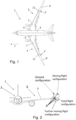
- Figure 1 is a plan view of an aircraft 1.
- the aircraft comprises a central fuselage 3 and two main wings 5 extending outwardly from respective wing roots 5'.
- Each wing 5 comprises a fixed wing 7 extending from the root 5' to the tip 7'.
- the wing 5 also comprises a moveable wing tip device 9, in the form of a planar wing tip extension.
- the wing tip device 9 is rotatably mounted about a hinge 11. This hinge 11, may be oriented non-parallel (or 'flared') to the line of flight direction F.
- the hinge 11 may alternatively be parallel to the line of flight direction F.
- the wing tip device 9 is fixed with respect to the fixed wing 7.
- the wing tip device 9 may be an extension of the fixed wing. Accordingly, the upper surface 7a and lower surface 7b of the fixed wing 7 may be continuous with the upper surface 9a and lower surface 9b of the wing tip device 9 (see Figure 3a and the second from lowermost position in Figure 2 ).
- the leading and trailing edges of the fixed wing 7 may also be continuous with the respective leading and trailing edges of the wing tip device 9.
- Such an arrangement is beneficial as it provides a relatively large wing span, thereby providing an aerodynamically efficient aircraft.
- a large span can result in correspondingly large loads on the wing 5, particularly a large wing root bending moment, and especially during high load events such as gusts or extreme maneuvers.
- This large wing root bending moment for a relatively large span wing can be an issue.
- the wing 5 must be arranged to cope with these maximum loads, which can result in a relatively heavy wing, which may be prohibitive.
- the ability of the wing tip device 9 to move substantially freely in a moving flight configuration seeks to address that problem.
- the wing tip device 9 is substantially freely rotatable about the hinge 11 with passive damping as will be described further below.
- the wing tip device 9 is rotatable, upwards, such that the lower surfaces between the fixed wing 7 and the wing tip device 9 are no longer continuous with one another. Furthermore, if the hinge 11 is angled with respect to the streamwise direction (i.e. opposite and parallel to the line of flight direction F) when the wing tip device 9 rotates upwardly, the mean incidence of the wing tip device 9 is reduced.
- the wing tip device 9 is also rotatable downwards, such that the upper faces between the fixed wing 7 and the wing tip device 9 are no longer continuous with one another.
- the loads on the wing 5, generated by the wing tip device 9, are significantly reduced.
- the wing tip device 9 may be released to either of these configurations during flight (described in more detail below).
- the maximum load the wing needs to be designed for may be reduced, and thus the wing 5 can be made relatively lightweight.
- the wing tip device 9 is also configurable to a ground configuration in which the wing tip device 9 is rotated yet further, to a substantially upright position (shown in Figure 2d and the upright position in Figure 2a ).
- the wing tip device is moveable to this configuration when it is on the ground (described in more detail below).
- the span of the aircraft 1 is reduced.
- the aircraft 1 can have a large span (exceeding airport gate compatibility limits) during flight, but is still able to comply with gate limits when on the ground.
- the hinge 111 allows both upward and downward rotation of the wing tip device 9 in the moving flight configuration. Such an arrangement enables both positive-g and negative-g loads to be alleviated.
- Figures 4a and 4b show an example of an actuation system 20 for rotating the wing tip device 9 about the hinge 11.
- the actuation system 20 comprises a motor 22, at least one geared rotary actuator (GRA) 24, and a clutch 28.
- the actuation system 20 comprises a plurality of geared rotary actuators 24, the geared rotary actuators 24 are arranged along the hinge line of the hinge 11.
- the motor 22 may form part of a power drive unit (PDU) incorporating a brake, or a separate brake 23 may be provided as illustrated in Figures 4a and 4b .
- the geared rotary actuator 24 is a rotary actuator arranged to convert a first rotary motion into a different second rotary motion, e.g. at a different rate of angular rotation and/or torque and/or direction.
- geared rotary actuator (GRA) 'slices' 24 arranged along the hinge line of the hinge 11.
- the three GRAs may be driven off a common shaft 26a coupled to the motor 22.
- the shaft 26a may have a shaft axis of rotation coaxial with the hinge line.
- the motor 22 (or PDU) is arranged at one end of the three GRA slices.
- the GRAs 24 are each arranged on the hinge line of the hinge 11.
- a fairing 30 is shown in Figure 4a in dashed line.
- the fairing 30 is sized to accommodate the actuation system 20.
- the clutch 28 may have the same outer diameter as each of the GRAs 24 as illustrated in Figure 4c such that the frontal surface area of the actuation system 20, and hence fairing 30, is minimized.
- the shaft 26a has a diameter significantly less than the diameter of the GRAs, for example less than half the diameter.
- the GRAs 24 each have a first knuckle 24a (or pair of first knuckles) coupled to the fixed wing 7 and a second knuckle 24b (or pair of second knuckles) coupled to the wing tip device 9, such as shown in Figure 5 .
- Each of the GRAs 24 is substantially identical and comprises an internal gearing to apply a gear ratio to torque applied to the GRA via the common shaft 26a.
- the motor 22 is activated to drive the common drive shaft 26a via the gearbox 26, the second knuckles 24b rotate relative to the first knuckles 24a of the GRAs 24. This drives the articulation of the wing tip device 9 relative to the fixed wing 7 about the hinge 11.
- the rotation may be a positive or negative rotation.
- a mass 40 may be fixed in rotation to the shaft 26a and disposed radially outwardly from the shaft 26a (See Figures 4a to 4c ).
- the mass 40 may be an annulus, wheel, ring, or any other suitable configuration. In this manner, the shaft 26a can extend through a hole in the mass 40, although the mass may alternatively be positioned between two sections of a split shaft (not shown) - either integrally formed or separately formed.
- Figure 6b shows the effect of the mass 40 on flap-bend mode coupling, in which the local minima of damping is shifted to a slightly higher airspeed than the example without the mass 40, whilst the damping around this local minima is also increased. By delaying the frequency coalescence there is more aero damping available to help ensure stability.
- the angular velocity of the wing tip device 9 is less than the angular velocity of the shaft 26a. Consequently, fixing the mass 40 to the shaft 26a, rather than directly to the wing tip device 9, achieves a comparatively higher rotational inertia as the inertia of the mass 40 increases as the square of the gear ratio between the motion of the wing tip device 9 and the motion of the shaft 26a with which the mass 40 rotates.
- the rotational inertia developed by the mass 40 will be dependent on several factors, including its mass and diameter.
- a high-density material is typically favored due to the increased rotational inertia that is developed compared to a similarly sized mass 40 having a lower density.
- the mass 40 may comprise tungsten, or a similarly dense material having a density of greater than 10,000 kg/m 3 , and more preferably greater than 15,000 kg/m 3 .
- the mass 40 may have a density greater than the density of the components of the actuation system 20, such as the clutch 28, gearbox 26 and geared rotary actuators 24.
- the inertia developed is greater than that otherwise developed by adding the mass to the wing tip device 9.
- the mass 40 may be less than approximately 20% of the mass of the wing tip device 9, or less than approximately 15%, and less than approximately 10% of the mass of the combined wing tip device 9 and actuation system 20, or less than 7%, whilst increasing the rotational inertia of the wing tip device 9 about the hinge 11 by 20% or more, 30% or more, 40% or more, or even 50% or more, than would be achieved by the same aircraft wing 5 without the mass 40.
- mass 40 can be varied to tailor the mass 40 to in turn vary the rotational inertia produced by the mass 40.
- a mass 40 may be selected for assembly into an actuation system 20 dependent on the flight handling requirements of the aircraft 1.
- the frequency at which the wing tip device 9 oscillates about the hinge 11 when the clutch 28 is disengaged during flight can be tailored.
- the mass 40 may be tailored to select a frequency of the wing tip device 9 oscillation about the hinge 11 that does not intersect with a natural frequency of the wing tip device 9 at an airspeed above a maximum design speed of the wing 5, or alternatively does intersect with a natural frequency of the wing tip device 9 at an airspeed above a maximum design speed of the wing 5, so as to avoid flutter.
- the mass 40 may be disposed on an opposite side of the clutch 28 to the motor 22. It will be appreciated that reference to the "side” refers to the relative positions along the driveline rather than necessarily their physical position on the wing 5.
- Engaging the clutch 28 enables the motor 22 to drive the GRAs 24 in a driving mode to rotate the wing tip device 9 about the hinge 11.
- An example of the actuation system 20 operating in a driving mode is illustrated by Figure 7a , the curved arrow indicating the direction (e.g. anticlockwise when looking aft) in which the motor 22 rotates the wing tip device 9. It is noted that the motor 22 may alternatively rotate the wing tip device 9 in an opposite (e.g. clockwise) direction about the hinge 11.
- Figure 7b illustrates how the clutch 28 and brake 23 are configured to allow the motor 22 to drive the wing tip device 9.
- Disengaging the clutch 28 enables the GRAs 24 to substantially freely rotate, thereby allowing substantially free rotation (with passive damping due to the mechanical resistance of the actuation system) of the wing tip device 9 relative to the fixed wing 7 about the hinge 11 when in a flapping mode of operation.
- the wing tip device 9 may be entirely passively actuated in the flapping mode once the brake 23 and clutch 28 are released. For example, the wing tip device 9 may be moved under the action of aerodynamic forces and/or gravity.
- the option to brake or release the wing tip device 9 may be referred to as a "semi-aeroelastic" arrangement.
- FIG. 8a A schematic representation of the actuation system 20 operating in a flapping mode is illustrated by Figure 8a , the curved arrow indicating allowable rotation of the wing tip device 9.
- Figure 8b illustrates how the clutch 28 and brake 23 are configured to allow the wing tip device 9 to freely rotate about the hinge 11.
- An increase in the gear ratio between the GRAs 24 and the motor 22 can be provided by the addition of a gearbox 26, such as shown in Figures 9a and 9b .
- a gearbox 26 is provided between the clutch 28 and the motor 22.
- the gearbox 26 may be provided between the GRAs 24 and the clutch 28, such as shown in Figures 10a and 10b .
- An advantage of this arrangement is that the clutch 28 may be designed to handle lower torque, as it is arranged before the gear ratio is applied to the torque from the motor 22 to the gearbox 26. This may reduce the size, weight, cost and complexity of the clutch 28.
- the mass 40 is disposed between the GRAs 24 and the gearbox 26.
- the mass 40 may be disposed between the clutch 28 and the gearbox 26 in order to take advantage of the gear ratio of the gearbox 26, i.e. the mass 40 is positioned upstream of the gearbox 26 towards the motor 22 due to the increased rotational speed of the shaft 26a at this point compared to downstream of the gearbox 26 towards the GRAs 24.
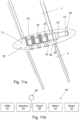
- An example of this arrangement is shown in Figures 11a and 11b .
- the gearbox 26 When the clutch 28 is disengaged, the gearbox 26 may be back driveable such that the gearbox 26 is operable by movement of the wing tip device 9 rotating about the hinge 11.
- the clutch 28 may be disengaged during flight for a number of further reasons. Allowing the wing tip device 9 to rotate substantially freely may be used to alleviate loads acting on the wing 5 as a result of external forces. As such, the maximum load the wing 5 needs to be designed for may be reduced, and thus the wing 5 can be made comparatively lightweight. Alternatively, the wing tip device 9 may be allowed to freely rotate such that span of the wing 5 is effectively reduced. Reducing the span of the wing 5 may be beneficial for example during relatively low speed or altitude flying where high levels of lift are not required, or when a relatively high roll rate is required.
- the actuation system 20 When the brake 23 (optionally of the PDU) is engaged and the clutch 28 is also engaged, the actuation system 20 operates in a braked mode in which the brake 23 acts to prevent rotation of the wing tip device 9 relative to the fixed wing 7 about the hinge 11.
- the braked mode of operation may correspond to a zero or non-zero angular position of the wing tip device 9 about the hinge 11. In this zero position the upper surface 9a and lower surface 9b of the wing tip device 9 form a substantially zero angle with the upper surface 7a and lower surface 7b of the fixed wing 7 such that the overall span of the wing 5 is at a maximum.
- a schematic representation of the actuation system 20 operating in a braked mode is illustrated by Figure 13a.
- Figure 13b illustrates how the clutch and brake are configured to prevent the wing tip device 9 rotating about the hinge 11.
- the actuation system 20 may further be operable in a fixed mode in which the clutch 28 is engaged and the brake 23 is disengaged such that the motor 22 may drive rotation of the wing tip device 9 about the hinge 11.
- a schematic representation of the actuation system 20 operating in a fixed mode is illustrated by Figure 14a , the dashed line indicating a non-zero target position of the wing tip device 9, and the curved arrow indicating the direction in which the motor 22 is driving the wing tip device 9 to achieve the target position.
- Figure 14b illustrates how the clutch and brake are configured to allow the motor 22 to drive the wing tip device 9.
- the actuation system 20 may be operable in any combination of the above-described operation modes and may change between modes of operation during flight.
- the mass 40 is disposed between the geared rotary actuators 24 and the clutch 28.
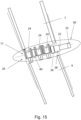
- the mass 40 may be disposed forward of the geared rotary actuators 24 towards the leading edge of the wing 5, such as shown in Figure 15 , such that the mass 40 is closer to the leading edge of the wing 5 than the geared rotary actuators 24.
- Positioning of the mass 40 forward of the geared rotary actuators 24 can be beneficial for packaging the actuation system 20 within the fairing 30.
- the mass 40 may have a diameter substantially the same as the diameter of the geared rotary actuators 24, gearbox 26, and other components of the actuation system 20 in order to retain compact packaging within the fairing 30.
- the mass 40 may be positioned between a pair of geared rotary actuators 24, such as shown in Figure 16 .
- Figure 17a shows a further embodiment (combinable with any of the previous disclosures) wherein the actuator mechanism 20 comprises a second gearbox 27, the second gearbox 27 arranged between the clutch 28 and the motor 22.
- the actuator mechanism 20 comprises a second gearbox 27, the second gearbox 27 arranged between the clutch 28 and the motor 22.
- Providing a gearbox 26 and a second gearbox 27 allows torque from the motor 22 to be increased in two stages, first by the second gearbox 27 before it is transferred through the clutch 28 to be again increased by the gearbox 26.
- the gear ratio and hence size of each of the gearbox 26 and second gearbox 27 may be made smaller than were a single gearbox 26 used as shown in previous examples. This may be beneficial in reducing the overall size of the actuation system 20 and hence the size of any fairing 30 arranged thereabout.
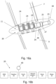
- the actuator mechanism 20 may alternatively be configured as illustrated in Figure 18a, with the motor 22 arranged on the opposite side of the geared rotary actuators 24 to the clutch 28 and gearbox 26.
- This arrangement may position the clutch 28 and gearbox 26 ahead of the leading edge of the wing 5 as shown in Figure 18a, which may be beneficial for example for packaging components within the fairing 30.
- FIG. 18b An example of an actuation system 20 configured as such is shown in exploded view in Figure 18b.
- a drive shaft 27a connected to the second gearbox 27 transfers a torque to the clutch 28 but does not act on the geared rotary actuators 24.
- the clutch 28 transfers torque to the gearbox 26 which in turn drives the geared rotary actuators 24, for example using the common shaft 26a as illustrated in Figure 4c on which a mass 40 is fixed (not shown in Figure 18b).
Landscapes
- Engineering & Computer Science (AREA)
- Aviation & Aerospace Engineering (AREA)
- Mechanical Engineering (AREA)
- Automation & Control Theory (AREA)
- Transmission Devices (AREA)
Abstract
An aircraft wing comprises a fixed wing with a tip, and a wing tip device rotatably mounted on a hinge at the tip of the fixed wing, such that the wing tip device is rotatable about the hinge, and an actuation system for rotating the wing tip device about the hinge, wherein the actuation system comprises a motor, at least one geared rotary actuator, a reduction gearbox, a clutch for selectively decoupling rotation of the motor from rotation of the geared rotary actuator, the geared rotary actuator is driveable by the motor and arranged to convert rotary motion into a different rotary motion and is arranged to rotate the wing tip device relative to the tip of the fixed wing, wherein the clutch is coupled to the geared rotary actuator by a shaft and the shaft is fixed in rotation to a mass disposed radially outwardly from the shaft.
Description
- The present invention relates to an aircraft wing with a moveable wing tip device.
- Using a moveable wing tip device during flight is known, e.g. from
WO2017118832 . This document teaches an aircraft wing having a fixed wing with a wing tip device moveably mounted at the tip thereof, wherein the fixed wing has an upper surface and a lower surface, and the wing tip device has an upper surface and a lower surface, and the wing tip device is operable between: (i) a flight configuration for use during flight, in which configuration the upper and lower surfaces of the wing tip device are continuations of the upper and lower surfaces of the fixed wing; and (ii) a load alleviating configuration for load alleviation during flight, in which configuration the wing tip device is moved relative to the fixed wing such that at least one of the upper and lower surfaces of the wing tip device is moved away from the respective surface of the fixed wing, and the load on the wing is reduced; wherein the aircraft comprises a restraining assembly operable between a restraining mode in which the wing tip device is held in the flight configuration using a restraining force, and a releasing mode in which the restraining force on the wing tip device is released, such that the wing tip device is able to adopt the load alleviating configuration. - The wing tip device may be entirely passively actuated to the load-alleviating configuration once the restraining assembly is in releasing mode. It may be moved under the action of aerodynamic forces urging the wing tip device towards the load-alleviating configuration. Having the restraining assembly in combination with this hinged wing tip device may be referred to as a "semi-aeroelastic" arrangement.
- The wing tip device may be rotatably mounted on a hinge at the tip of the wing, such that it may rotate, about the hinge, between the flight and load alleviating configurations. The wing tip device may also be moveable about the same hinge to a ground configuration for use during ground-based operations, in which ground configuration the wing tip device is moved away from the flight configuration such that the span of the aircraft wing is reduced.
- An actuation system may be arranged to move the wing tip device between the flight configuration and the ground configuration. The actuation system may also be arranged to move the wing tip device from the load alleviating configuration back to the flight configuration.
- It has been found that when in the load alleviating condition, movement of the wing tip device may need to be tuned.
- A first aspect of the invention provides an aircraft wing comprises a fixed wing with a tip, and a wing tip device rotatably mounted on a hinge at the tip of the fixed wing, such that the wing tip device is rotatable about the hinge, and an actuation system for rotating the wing tip device about the hinge, wherein the actuation system comprises a motor, at least one geared rotary actuator, a reduction gearbox, a clutch for selectively decoupling rotation of the motor from rotation of the geared rotary actuator, the geared rotary actuator is driveable by the motor and arranged to convert rotary motion into a different rotary motion and is arranged to rotate the wing tip device relative to the tip of the fixed wing, wherein the clutch is coupled to the geared rotary actuator by a shaft and the shaft is fixed in rotation to a mass disposed radially outwardly from the shaft.
- With this arrangement, the rotational inertia of the wing tip device is increased when it rotates relative to the fixed wing. This increase in rotational inertia of the wing tip device reduces the wing tip flapping frequency and thus increases flutter speed. The addition of a mass that rotates with the shaft minimises the additional weight that is required to reduce the gradient at which the frequency of flapping of the wing tip device increases with aircraft speed compared to alternative solutions such as adding weight to the wing tip device itself because the shaft motion is geared with respect to motion of the wing tip device and the inertia of the mass coupled to the shaft is squared with the gear ratio of the reduction gearbox.
- The hinge may have a hinge line and the shaft may have a shaft axis of rotation which is coaxial with the hinge line.
- The geared rotary actuator may be arranged along a hinge line of the hinge and has an outer diameter. The shaft may have a shaft diameter significantly less than the outer diameter of the geared rotary actuator, and the mass may have an outer diameter about the shaft axis which is substantially the same as the outer diameter of the geared rotary actuator.
- The mass may rotate as the wing tip device rotates about the hinge.
- The mass may rotate at an angular velocity faster than the wing tip device rotation about the hinge due to the gearing of the geared rotary actuator.
- The mass may be an annulus or a wheel or a ring.
- The shaft may extend through a hole in the mass.
- The mass may comprise Tungsten.
- The mass may be less than approximately 20% of a mass of the wing tip device, preferably less than 15%.
- The mass may be less than approximately 10% of a mass of the combined wing tip device and actuation system, preferably less than 7%.
- The mass may increase the rotational inertia of the wing tip device about the hinge by at least 20% compared to the same aircraft wing without the mass, preferably by at least 30% or at least 40% or at least 50%.
- An aircraft wing may further comprise a plurality of the geared rotary actuators arranged along a hinge line of the hinge.
- The mass may be disposed between the geared rotary actuators and the clutch.
- The mass may be disposed forward of the geared rotary actuator(s) towards a leading edge of the wing.
- The mass may be disposed between a pair of the geared rotary actuators.
- The actuation system may have a maximum damping value which allows oscillating flapping movement of the wing tip device rotating about the hinge during normal operation when the clutch is disengaged.
- The actuation system may be back driveable when the clutch is disengaged to decouple rotation of the motor from rotation of the geared rotary actuator as the wing tip device rotates about the hinge.
- The actuation system may further comprise a reduction gearbox.
- The reduction gearbox may be disposed between the clutch and the geared rotary actuator along a drive train between the motor and the geared rotary actuator.
- The actuation system may further comprise a brake for preventing motion of the geared rotary actuator when the clutch is engaged.
- The actuation system may be operable in i) a driving mode in which the clutch is engaged and the motor is driven to rotate the wing tip device about the hinge; ii) a flapping mode in which the clutch is disengaged and the wing tip device is rotatable about the hinge by forces external to the wing tip device; and iii) a braked mode in which the clutch is engaged and the brake prevents rotation of the wing tip device about the hinge.
- The geared rotary actuator may have a first knuckle fixed to the fixed wing, and a second knuckle fixed to the wing tip device, wherein the first knuckle and the second knuckle are driven to rotate with respect to each other by the geared rotary actuator using motive force provided by the motor.
- The clutch may be configured to be disengaged during flight for one of more of a) loads alleviation, or b) when the aircraft is flying at relatively low speed or altitude and a relatively high roll rate is required.
- A further aspect of the invention provides a method of tuning an aircraft wing, wherein the aircraft wing is in accordance with the first aspect, and the method comprises tailoring the mass to vary the inertia and therefore the frequency at which the wing tip device oscillates about the hinge when the clutch is disengaged during flight.
- Embodiments of the invention will now be described with reference to the accompanying drawings, in which:
-
Figure 1 shows a plan view of an aircraft with a wing and a folding wing tip device; -
Figure 2 shows a front view of the aircraft ofFigure 1 with the wing tip device in various configurations; -
Figures 3a, 3b, 3c and 3d show the wing tip device ofFigure 2 in detail; -
Figure 4a shows schematically an actuation system for moving the wing tip device in accordance with the invention; -
Figure 4b shows the actuation system ofFigure 4a more generally in block diagram form; -
Figure 4c shows a detailed view of a section of the actuation system ofFigure 4a ; -
Figure 5 shows a mechanical actuator according to the invention; -
Figure 6a shows a graph indicating the increase in flutter speed due to the addition of the mass to the actuation system; -
Figure 6b shows a graph indicating the change in flap-bend mode coupling due to the addition of the mass to the actuation system; -
Figure 7a shows schematically a wing tip device operating in a driving mode of operation; -
Figure 7b shows a representation of an actuation system configured to operate in a driving mode; -
Figure 8a shows schematically a wing tip device operating in a flapping mode of operation; -
Figure 8b shows a representation of an actuation system configured to operate in a flapping mode; -
Figure 9a shows schematically a second example of an actuation system for moving the wing tip device in accordance with the invention; -
Figure 9b shows the actuation system ofFigure 9a more generally in block diagram form; -
Figure 10a shows schematically a third example of an actuation system for moving the wing tip device in accordance with the invention; -
Figure 10b shows the actuation system ofFigure 10a more generally in block diagram form; -
Figure 11a shows schematically a fourth example of an actuation system for moving the wing tip device in accordance with the invention; -
Figure 11b shows the actuation system ofFigure 11a more generally in block diagram form; -
Figure 12a shows schematically a wing tip device operating in a braked mode of operation; -
Figure 12b shows a representation of an actuation system configured to operate in a braked mode; -
Figure 13a shows schematically a wing tip device operating in a fixed mode of operation; -
Figure 13b shows a representation of an actuation system configured to operate in a fixed mode; -
Figure 14 shows schematically a fifth example of an actuation system for moving the wing tip device in accordance with the invention; -
Figure 15 shows schematically a sixth example of an actuation system for moving the wing tip device in accordance with the invention; -
Figure 16a shows schematically a seventh example of an actuation system for moving the wing tip device in accordance with the invention; -
Figure 16b shows the actuation system ofFigure 16a more generally in block diagram form; -
Figure 17a shows schematically an eighth example of an actuation system for moving the wing tip device in accordance with the invention; -
Figure 17b shows the actuation system of Figure 18a more generally in block diagram form. -
Figure 1 is a plan view of anaircraft 1. The aircraft comprises acentral fuselage 3 and twomain wings 5 extending outwardly fromrespective wing roots 5'. - Each
wing 5 comprises a fixedwing 7 extending from theroot 5' to the tip 7'. At the tip 7' of the fixedwing 7, thewing 5 also comprises a moveablewing tip device 9, in the form of a planar wing tip extension. Thewing tip device 9 is rotatably mounted about ahinge 11. Thishinge 11, may be oriented non-parallel (or 'flared') to the line of flight direction F. Thehinge 11 may alternatively be parallel to the line of flight direction F. - In a fixed flight configuration, the
wing tip device 9 is fixed with respect to the fixedwing 7. Thewing tip device 9 may be an extension of the fixed wing. Accordingly, theupper surface 7a andlower surface 7b of the fixedwing 7 may be continuous with theupper surface 9a andlower surface 9b of the wing tip device 9 (seeFigure 3a and the second from lowermost position inFigure 2 ). The leading and trailing edges of the fixedwing 7 may also be continuous with the respective leading and trailing edges of thewing tip device 9. Such an arrangement is beneficial as it provides a relatively large wing span, thereby providing an aerodynamically efficient aircraft. - However, a large span can result in correspondingly large loads on the
wing 5, particularly a large wing root bending moment, and especially during high load events such as gusts or extreme maneuvers. This large wing root bending moment for a relatively large span wing can be an issue. Thewing 5 must be arranged to cope with these maximum loads, which can result in a relatively heavy wing, which may be prohibitive. - The ability of the
wing tip device 9 to move substantially freely in a moving flight configuration (seeFigures 2 ,3b and 3d ) seeks to address that problem. In this configuration, thewing tip device 9 is substantially freely rotatable about thehinge 11 with passive damping as will be described further below. - As shown in
Figure 3b and the second from uppermost position inFigure 2 , thewing tip device 9 is rotatable, upwards, such that the lower surfaces between thefixed wing 7 and thewing tip device 9 are no longer continuous with one another. Furthermore, if thehinge 11 is angled with respect to the streamwise direction (i.e. opposite and parallel to the line of flight direction F) when thewing tip device 9 rotates upwardly, the mean incidence of thewing tip device 9 is reduced. - As shown in
Figure 3d and the lowermost position inFigure 2 , thewing tip device 9 is also rotatable downwards, such that the upper faces between thefixed wing 7 and thewing tip device 9 are no longer continuous with one another. - In the moving flight configuration and the further moving flight configuration, the loads on the
wing 5, generated by thewing tip device 9, are significantly reduced. Thewing tip device 9 may be released to either of these configurations during flight (described in more detail below). By providing this load alleviation function during flight, the maximum load the wing needs to be designed for may be reduced, and thus thewing 5 can be made relatively lightweight. - The
wing tip device 9 is also configurable to a ground configuration in which thewing tip device 9 is rotated yet further, to a substantially upright position (shown inFigure 2d and the upright position inFigure 2a ). The wing tip device is moveable to this configuration when it is on the ground (described in more detail below). Once rotated to such a position, the span of theaircraft 1 is reduced. Thus, theaircraft 1 can have a large span (exceeding airport gate compatibility limits) during flight, but is still able to comply with gate limits when on the ground. - As shown in
Figures 3d , the hinge 111 allows both upward and downward rotation of thewing tip device 9 in the moving flight configuration. Such an arrangement enables both positive-g and negative-g loads to be alleviated. -
Figures 4a and 4b show an example of anactuation system 20 for rotating thewing tip device 9 about thehinge 11. Theactuation system 20 comprises amotor 22, at least one geared rotary actuator (GRA) 24, and a clutch 28. Where theactuation system 20 comprises a plurality of gearedrotary actuators 24, the gearedrotary actuators 24 are arranged along the hinge line of thehinge 11. Themotor 22 may form part of a power drive unit (PDU) incorporating a brake, or aseparate brake 23 may be provided as illustrated inFigures 4a and 4b . The gearedrotary actuator 24 is a rotary actuator arranged to convert a first rotary motion into a different second rotary motion, e.g. at a different rate of angular rotation and/or torque and/or direction. - In the illustrated example, there are three geared rotary actuator (GRA) 'slices' 24 arranged along the hinge line of the
hinge 11. The three GRAs may be driven off acommon shaft 26a coupled to themotor 22. Theshaft 26a may have a shaft axis of rotation coaxial with the hinge line. The motor 22 (or PDU) is arranged at one end of the three GRA slices. TheGRAs 24 are each arranged on the hinge line of thehinge 11. - A fairing 30 is shown in
Figure 4a in dashed line. The fairing 30 is sized to accommodate theactuation system 20. The clutch 28 may have the same outer diameter as each of theGRAs 24 as illustrated inFigure 4c such that the frontal surface area of theactuation system 20, and hence fairing 30, is minimized. Theshaft 26a has a diameter significantly less than the diameter of the GRAs, for example less than half the diameter. - The
GRAs 24 each have afirst knuckle 24a (or pair of first knuckles) coupled to the fixedwing 7 and asecond knuckle 24b (or pair of second knuckles) coupled to thewing tip device 9, such as shown inFigure 5 . Each of theGRAs 24 is substantially identical and comprises an internal gearing to apply a gear ratio to torque applied to the GRA via thecommon shaft 26a. When themotor 22 is activated to drive thecommon drive shaft 26a via thegearbox 26, thesecond knuckles 24b rotate relative to thefirst knuckles 24a of theGRAs 24. This drives the articulation of thewing tip device 9 relative to the fixedwing 7 about thehinge 11. The rotation may be a positive or negative rotation. - To increase the effective rotational inertia of the
wing tip device 9 so as to reduce the wing tip flapping frequency and thus increase flutter speed, amass 40 may be fixed in rotation to theshaft 26a and disposed radially outwardly from theshaft 26a (SeeFigures 4a to 4c ). Themass 40 may be an annulus, wheel, ring, or any other suitable configuration. In this manner, theshaft 26a can extend through a hole in themass 40, although the mass may alternatively be positioned between two sections of a split shaft (not shown) - either integrally formed or separately formed. The addition of the mass 40 to theactuation system 20, and in particular to therotatable shaft 26a, minimises the additional weight that is required to reduce the gradient at which the frequency of flapping of thewing tip device 9 increases with aircraft speed compared to alternative solutions such as adding weight to thewing tip device 9. This is shown inFigure 6a , in which addition of the mass 40 to theactuation system 20 provides increased rotational inertia that acts decrease the wing tip flapping frequency (dottedline 61 indicates theactuation system 20 with a mass 40) relative to awing 5 without the mass (solid line 60 indicates theactuation system 20 without a mass).Figure 6b shows the effect of themass 40 on flap-bend mode coupling, in which the local minima of damping is shifted to a slightly higher airspeed than the example without themass 40, whilst the damping around this local minima is also increased. By delaying the frequency coalescence there is more aero damping available to help ensure stability. - In this manner, as the
shaft 26a is rotated, themass 40 rotates in accordance to develop rotational inertia that dampens the movement of thewing tip device 9. - As the GRA's comprise reduction gearing, the angular velocity of the
wing tip device 9 is less than the angular velocity of theshaft 26a. Consequently, fixing themass 40 to theshaft 26a, rather than directly to thewing tip device 9, achieves a comparatively higher rotational inertia as the inertia of the mass 40 increases as the square of the gear ratio between the motion of thewing tip device 9 and the motion of theshaft 26a with which themass 40 rotates. - It will be appreciated that the rotational inertia developed by the
mass 40 will be dependent on several factors, including its mass and diameter. A high-density material is typically favored due to the increased rotational inertia that is developed compared to a similarlysized mass 40 having a lower density. Themass 40 may comprise tungsten, or a similarly dense material having a density of greater than 10,000 kg/m3, and more preferably greater than 15,000 kg/m3. Themass 40 may have a density greater than the density of the components of theactuation system 20, such as the clutch 28,gearbox 26 and gearedrotary actuators 24. - Due to the rotation of the
mass 40, the inertia developed is greater than that otherwise developed by adding the mass to thewing tip device 9. For instance, themass 40 may be less than approximately 20% of the mass of thewing tip device 9, or less than approximately 15%, and less than approximately 10% of the mass of the combinedwing tip device 9 andactuation system 20, or less than 7%, whilst increasing the rotational inertia of thewing tip device 9 about thehinge 11 by 20% or more, 30% or more, 40% or more, or even 50% or more, than would be achieved by thesame aircraft wing 5 without themass 40. - It will be appreciated that the properties of the
mass 40, such as its size and weight, can be varied to tailor themass 40 to in turn vary the rotational inertia produced by themass 40. For instance, amass 40 may be selected for assembly into anactuation system 20 dependent on the flight handling requirements of theaircraft 1. - In this manner, the frequency at which the
wing tip device 9 oscillates about thehinge 11 when the clutch 28 is disengaged during flight can be tailored. For instance, themass 40 may be tailored to select a frequency of thewing tip device 9 oscillation about thehinge 11 that does not intersect with a natural frequency of thewing tip device 9 at an airspeed above a maximum design speed of thewing 5, or alternatively does intersect with a natural frequency of thewing tip device 9 at an airspeed above a maximum design speed of thewing 5, so as to avoid flutter. - To ensure the
mass 40 develops rotational inertia when the clutch 28 is disengaged (e.g. during the flapping mode), themass 40 may be disposed on an opposite side of the clutch 28 to themotor 22. It will be appreciated that reference to the "side" refers to the relative positions along the driveline rather than necessarily their physical position on thewing 5. - Engaging the clutch 28 enables the
motor 22 to drive theGRAs 24 in a driving mode to rotate thewing tip device 9 about thehinge 11. An example of theactuation system 20 operating in a driving mode is illustrated byFigure 7a , the curved arrow indicating the direction (e.g. anticlockwise when looking aft) in which themotor 22 rotates thewing tip device 9. It is noted that themotor 22 may alternatively rotate thewing tip device 9 in an opposite (e.g. clockwise) direction about thehinge 11.Figure 7b illustrates how the clutch 28 andbrake 23 are configured to allow themotor 22 to drive thewing tip device 9. - Disengaging the clutch 28 enables the
GRAs 24 to substantially freely rotate, thereby allowing substantially free rotation (with passive damping due to the mechanical resistance of the actuation system) of thewing tip device 9 relative to the fixedwing 7 about thehinge 11 when in a flapping mode of operation. Thewing tip device 9 may be entirely passively actuated in the flapping mode once thebrake 23 and clutch 28 are released. For example, thewing tip device 9 may be moved under the action of aerodynamic forces and/or gravity. The option to brake or release thewing tip device 9 may be referred to as a "semi-aeroelastic" arrangement. A schematic representation of theactuation system 20 operating in a flapping mode is illustrated byFigure 8a , the curved arrow indicating allowable rotation of thewing tip device 9.Figure 8b illustrates how the clutch 28 andbrake 23 are configured to allow thewing tip device 9 to freely rotate about thehinge 11. - An increase in the gear ratio between the
GRAs 24 and themotor 22 can be provided by the addition of agearbox 26, such as shown inFigures 9a and 9b . In this example, agearbox 26 is provided between the clutch 28 and themotor 22. - Alternatively, the
gearbox 26 may be provided between theGRAs 24 and the clutch 28, such as shown inFigures 10a and 10b . An advantage of this arrangement is that the clutch 28 may be designed to handle lower torque, as it is arranged before the gear ratio is applied to the torque from themotor 22 to thegearbox 26. This may reduce the size, weight, cost and complexity of the clutch 28. - In the examples of
figures 9 and10 , it will be noted that themass 40 is disposed between theGRAs 24 and thegearbox 26. Alternatively, themass 40 may be disposed between the clutch 28 and thegearbox 26 in order to take advantage of the gear ratio of thegearbox 26, i.e. themass 40 is positioned upstream of thegearbox 26 towards themotor 22 due to the increased rotational speed of theshaft 26a at this point compared to downstream of thegearbox 26 towards theGRAs 24. An example of this arrangement is shown inFigures 11a and 11b . - When the clutch 28 is disengaged, the
gearbox 26 may be back driveable such that thegearbox 26 is operable by movement of thewing tip device 9 rotating about thehinge 11. - The clutch 28 may be disengaged during flight for a number of further reasons. Allowing the
wing tip device 9 to rotate substantially freely may be used to alleviate loads acting on thewing 5 as a result of external forces. As such, the maximum load thewing 5 needs to be designed for may be reduced, and thus thewing 5 can be made comparatively lightweight. Alternatively, thewing tip device 9 may be allowed to freely rotate such that span of thewing 5 is effectively reduced. Reducing the span of thewing 5 may be beneficial for example during relatively low speed or altitude flying where high levels of lift are not required, or when a relatively high roll rate is required. - When the brake 23 (optionally of the PDU) is engaged and the clutch 28 is also engaged, the
actuation system 20 operates in a braked mode in which thebrake 23 acts to prevent rotation of thewing tip device 9 relative to the fixedwing 7 about thehinge 11. The braked mode of operation may correspond to a zero or non-zero angular position of thewing tip device 9 about thehinge 11. In this zero position theupper surface 9a andlower surface 9b of thewing tip device 9 form a substantially zero angle with theupper surface 7a andlower surface 7b of the fixedwing 7 such that the overall span of thewing 5 is at a maximum. A schematic representation of theactuation system 20 operating in a braked mode is illustrated byFigure 13a. Figure 13b illustrates how the clutch and brake are configured to prevent thewing tip device 9 rotating about thehinge 11. - The
actuation system 20 may further be operable in a fixed mode in which the clutch 28 is engaged and thebrake 23 is disengaged such that themotor 22 may drive rotation of thewing tip device 9 about thehinge 11. A schematic representation of theactuation system 20 operating in a fixed mode is illustrated byFigure 14a , the dashed line indicating a non-zero target position of thewing tip device 9, and the curved arrow indicating the direction in which themotor 22 is driving thewing tip device 9 to achieve the target position.Figure 14b illustrates how the clutch and brake are configured to allow themotor 22 to drive thewing tip device 9. - The
actuation system 20 may be operable in any combination of the above-described operation modes and may change between modes of operation during flight. - In the above-mentioned examples, the
mass 40 is disposed between the gearedrotary actuators 24 and the clutch 28. Alternatively, themass 40 may be disposed forward of the gearedrotary actuators 24 towards the leading edge of thewing 5, such as shown inFigure 15 , such that themass 40 is closer to the leading edge of thewing 5 than the gearedrotary actuators 24. Positioning of the mass 40 forward of the gearedrotary actuators 24 can be beneficial for packaging theactuation system 20 within thefairing 30. Furthermore, in any of the above examples, themass 40 may have a diameter substantially the same as the diameter of the gearedrotary actuators 24,gearbox 26, and other components of theactuation system 20 in order to retain compact packaging within thefairing 30. - In some examples, the
mass 40 may be positioned between a pair of gearedrotary actuators 24, such as shown inFigure 16 . -
Figure 17a shows a further embodiment (combinable with any of the previous disclosures) wherein theactuator mechanism 20 comprises asecond gearbox 27, thesecond gearbox 27 arranged between the clutch 28 and themotor 22. Providing agearbox 26 and asecond gearbox 27 allows torque from themotor 22 to be increased in two stages, first by thesecond gearbox 27 before it is transferred through the clutch 28 to be again increased by thegearbox 26. As such the gear ratio and hence size of each of thegearbox 26 andsecond gearbox 27 may be made smaller than were asingle gearbox 26 used as shown in previous examples. This may be beneficial in reducing the overall size of theactuation system 20 and hence the size of any fairing 30 arranged thereabout. Further, this may allow the reduction ratio of thegearbox 26 to be selected based on the desired damping characteristics of the hinge joint when back-driven, whilst still providing adequate torque to drive thewing tip device 9 using thesecond gearbox 27.Figure 17b shows this arrangement more generally in a block diagram. - The
actuator mechanism 20 may alternatively be configured as illustrated in Figure 18a, with themotor 22 arranged on the opposite side of the gearedrotary actuators 24 to the clutch 28 andgearbox 26. This arrangement may position the clutch 28 andgearbox 26 ahead of the leading edge of thewing 5 as shown in Figure 18a, which may be beneficial for example for packaging components within thefairing 30. Although shown to include asecond gearbox 27, this configuration may also be applied to actuation systems comprising asingle gearbox 26 only. An example of anactuation system 20 configured as such is shown in exploded view in Figure 18b. In this example, adrive shaft 27a connected to thesecond gearbox 27 transfers a torque to the clutch 28 but does not act on the gearedrotary actuators 24. Once engaged, the clutch 28 transfers torque to thegearbox 26 which in turn drives the gearedrotary actuators 24, for example using thecommon shaft 26a as illustrated inFigure 4c on which amass 40 is fixed (not shown in Figure 18b). - Where the word 'or' appears this is to be construed to mean 'and/or' such that items referred to are not necessarily mutually exclusive and may be used in any appropriate combination.
- Although the invention has been described above with reference to one or more preferred embodiments, it will be appreciated that various changes or modifications may be made without departing from the scope of the invention as defined in the appended claims.
Claims (15)
- An aircraft wing comprising a fixed wing with a tip, and a wing tip device rotatably mounted on a hinge at the tip of the fixed wing, such that the wing tip device is rotatable about the hinge, and an actuation system for rotating the wing tip device about the hinge, wherein the actuation system comprises a motor, at least one geared rotary actuator, a clutch for selectively decoupling rotation of the motor from rotation of the geared rotary actuator, the geared rotary actuator is driveable by the motor and arranged to convert rotary motion into a different rotary motion and is arranged to rotate the wing tip device relative to the tip of the fixed wing, wherein the clutch is coupled to the geared rotary actuator by a shaft and the shaft is fixed in rotation to a mass disposed radially outwardly from the shaft.
- An aircraft wing according to claim 1, wherein the hinge has a hinge line and the shaft has a shaft axis of rotation which is coaxial with the hinge line, preferably
wherein the geared rotary actuator is arranged along a hinge line of the hinge and has an outer diameter, the shaft has a shaft diameter significantly less than the outer diameter of the geared rotary actuator, and the mass has an outer diameter about the shaft axis which is substantially the same as the outer diameter of the geared rotary actuator. - An aircraft wing according to any preceding claim, wherein the mass rotates as the wing tip device rotates about the hinge, preferably
wherein the mass rotates at an angular velocity faster than the wing tip device rotation about the hinge due to the gearing of the geared rotary actuator. - An aircraft wing according to any preceding claim, wherein the mass is an annulus or a wheel or a ring; and/orwherein the shaft extends through a hole in the mass; and/orwherein the mass comprises Tungsten.
- An aircraft wing according to any preceding claim, wherein the mass is less than approximately 20% of a mass of the wing tip device, preferably less than 15%; and/or, wherein the mass is less than approximately 10% of a mass of the combined wing tip device and actuation system, preferably less than 7%; and/orwherein the mass increases the rotational inertia of the wing tip device about the hinge by at least 20% compared to the same aircraft wing without the mass, preferably by at least 30% or at least 40% or at least 50%.
- An aircraft wing according to any preceding claim, further comprising a plurality of the geared rotary actuators arranged along a hinge line of the hinge.
- An aircraft wing according to any preceding claim, wherein the mass is disposed forward of the geared rotary actuator(s) towards a leading edge of the wing.
- An aircraft wing according to any one of claims 1 to 6, wherein the mass is disposed between the geared rotary actuators and the clutch.
- An aircraft wing according to claim 6, wherein the mass is disposed between a pair of the geared rotary actuators.
- An aircraft wing according to any preceding claim, wherein the actuation system has a maximum damping value which allows oscillating flapping movement of the wing tip device rotating about the hinge during normal operation when the clutch is disengaged; and/or
wherein the actuation system is back driveable when the clutch is disengaged to decouple rotation of the motor from rotation of the geared rotary actuator as the wing tip device rotates about the hinge. - An aircraft wing according to any preceding claim, wherein the actuation system further comprises a reduction gearbox, preferably
wherein the reduction gearbox is disposed between the clutch and the geared rotary actuator along a drive train between the motor and the geared rotary actuator. - An aircraft wing according to any preceding claim, wherein the actuation system further comprises a brake for preventing motion of the geared rotary actuator when the clutch is engaged, preferably
wherein the actuation system is operable in i) a driving mode in which the clutch is engaged and the motor is driven to rotate the wing tip device about the hinge; ii) a flapping mode in which the clutch is disengaged and the wing tip device is rotatable about the hinge by forces external to the wing tip device; and iii) a braked mode in which the clutch is engaged and the brake prevents rotation of the wing tip device about the hinge. - An aircraft wing according to any preceding claim, wherein the geared rotary actuator has a first knuckle fixed to the fixed wing, and a second knuckle fixed to the wing tip device, wherein the first knuckle and the second knuckle are driven to rotate with respect to each other by the geared rotary actuator using motive force provided by the motor.
- An aircraft wing according to any preceding claim, wherein the clutch is configured to be disengaged during flight for one of more of a) loads alleviation, or b) when the aircraft is flying at relatively low speed or altitude and a relatively high roll rate is required.
- A method of tuning an aircraft wing, wherein the aircraft wing is in accordance with any preceding claim, and the method comprises tailoring the mass to vary the inertia and therefore the frequency at which the wing tip device oscillates about the hinge when the clutch is disengaged during flight.
Applications Claiming Priority (1)
| Application Number | Priority Date | Filing Date | Title |
|---|---|---|---|
| GB2309071.5A GB2630985B (en) | 2023-06-16 | 2023-06-16 | Moveable wing tip actuation system |
Publications (1)
| Publication Number | Publication Date |
|---|---|
| EP4477536A1 true EP4477536A1 (en) | 2024-12-18 |
Family
ID=91331011
Family Applications (1)
| Application Number | Title | Priority Date | Filing Date |
|---|---|---|---|
| EP24178828.0A Pending EP4477536A1 (en) | 2023-06-16 | 2024-05-29 | Moveable wing tip actuation system |
Country Status (4)
| Country | Link |
|---|---|
| US (1) | US12559229B2 (en) |
| EP (1) | EP4477536A1 (en) |
| CN (1) | CN119142506A (en) |
| GB (1) | GB2630985B (en) |
Families Citing this family (4)
| Publication number | Priority date | Publication date | Assignee | Title |
|---|---|---|---|---|
| GB2622057A (en) * | 2022-08-31 | 2024-03-06 | Airbus Operations Ltd | Fairing for folding wing tip |
| GB2631379B (en) * | 2023-06-16 | 2026-03-25 | Airbus Operations Ltd | Moveable wing tip actuation system |
| GB2644385A (en) * | 2024-09-30 | 2026-04-08 | Airbus Operations Ltd | Rotary actuator for an aircraft |
| EP4725831A1 (en) * | 2024-10-14 | 2026-04-15 | Goodrich Actuation Systems Limited | Foldable wing tip actuation system |
Citations (4)
| Publication number | Priority date | Publication date | Assignee | Title |
|---|---|---|---|---|
| WO2017118832A1 (en) | 2016-01-05 | 2017-07-13 | Airbus Operations Limited | An aircraft wing with a moveable wing tip device for load alleviation |
| CN110997483A (en) * | 2017-08-18 | 2020-04-10 | 空中客车运作有限责任公司 | Actuation unit for actuating a foldable wing tip section of a wing of an aircraft |
| GB2584668A (en) * | 2019-06-10 | 2020-12-16 | Airbus Operations Ltd | An aircraft wing with a moveable wing tip |
| US20220266984A1 (en) * | 2021-02-25 | 2022-08-25 | Airbus Operations Gmbh | Actuator assembly for moving a movable wing tip of an aircraft |
Family Cites Families (4)
| Publication number | Priority date | Publication date | Assignee | Title |
|---|---|---|---|---|
| GB2580345A (en) * | 2019-01-02 | 2020-07-22 | Airbus Operations Ltd | Actuator assembly for moving an aircraft wing tip device |
| CN111645849B (en) * | 2020-05-22 | 2022-02-08 | 中国商用飞机有限责任公司 | System and method for actuating and controlling a foldable wing tip of an aircraft wing |
| EP4071050B1 (en) | 2021-04-07 | 2025-05-07 | Airbus Operations GmbH | Drive system with integrated torque sensing device |
| GB2628524A (en) | 2022-11-16 | 2024-10-02 | Airbus Operations Ltd | Moveable wing tip actuation system |
-
2023
- 2023-06-16 GB GB2309071.5A patent/GB2630985B/en active Active
-
2024
- 2024-05-29 EP EP24178828.0A patent/EP4477536A1/en active Pending
- 2024-06-13 CN CN202410762655.6A patent/CN119142506A/en active Pending
- 2024-06-14 US US18/744,203 patent/US12559229B2/en active Active
Patent Citations (4)
| Publication number | Priority date | Publication date | Assignee | Title |
|---|---|---|---|---|
| WO2017118832A1 (en) | 2016-01-05 | 2017-07-13 | Airbus Operations Limited | An aircraft wing with a moveable wing tip device for load alleviation |
| CN110997483A (en) * | 2017-08-18 | 2020-04-10 | 空中客车运作有限责任公司 | Actuation unit for actuating a foldable wing tip section of a wing of an aircraft |
| GB2584668A (en) * | 2019-06-10 | 2020-12-16 | Airbus Operations Ltd | An aircraft wing with a moveable wing tip |
| US20220266984A1 (en) * | 2021-02-25 | 2022-08-25 | Airbus Operations Gmbh | Actuator assembly for moving a movable wing tip of an aircraft |
Also Published As
| Publication number | Publication date |
|---|---|
| US12559229B2 (en) | 2026-02-24 |
| CN119142506A (en) | 2024-12-17 |
| US20240417061A1 (en) | 2024-12-19 |
| GB2630985B (en) | 2025-08-27 |
| GB2630985A (en) | 2024-12-18 |
Similar Documents
| Publication | Publication Date | Title |
|---|---|---|
| EP4477536A1 (en) | Moveable wing tip actuation system | |
| EP3677503B1 (en) | Actuator assembly for moving an aircraft wing tip device | |
| JP6974616B2 (en) | Fluid control device assembly, fluid control device, and aircraft | |
| EP2555974B1 (en) | Method and apparatus for in-flight blade folding | |
| EP2121438B1 (en) | On-blade actuator for helicopter rotor blade control flaps | |
| US8083172B2 (en) | Combination spar and trunnion structure for a tilt rotor aircraft | |
| US7309043B2 (en) | Actuation device positioning systems and associated methods, including aircraft spoiler droop systems | |
| EP4619306A1 (en) | Moveable wing tip actuation system | |
| CN112591083B (en) | Folding collection rectification structure of paddle | |
| US20230174224A1 (en) | Aircraft | |
| US20040004163A1 (en) | Flight surface actuator | |
| CN106573678A (en) | Aerodynamically efficient lightweight vertical takeoff and landing aircraft with pivoting rotors and retracting rotor blades | |
| JPS58217704A (en) | Rotor apparatus and control thereof | |
| US12534186B2 (en) | Fold-lock and pitch-lock systems | |
| WO2022140135A1 (en) | Systems and methods for aircraft lift enhancement | |
| CN108674654B (en) | A cycloidal propeller-propeller compound high-speed aircraft | |
| US12552520B2 (en) | Moveable wing tip actuation system | |
| US20040113013A1 (en) | Rotary/fixed wing aircraft | |
| US20240158071A1 (en) | Aircraft wing | |
| CN104787328B (en) | A kind of rotor folding and unfolding mechanism being applicable to composite aircraft | |
| US7891612B2 (en) | Flap device | |
| JP3254845U (en) | High-speed VTOL (vertical take-off and landing aircraft) | |
| US12179914B2 (en) | Rotary wing air vehicle | |
| GB2148816A (en) | Aircraft lift rotors | |
| JPH04169399A (en) | Aircraft |
Legal Events
| Date | Code | Title | Description |
|---|---|---|---|
| PUAI | Public reference made under article 153(3) epc to a published international application that has entered the european phase |
Free format text: ORIGINAL CODE: 0009012 |
|
| STAA | Information on the status of an ep patent application or granted ep patent |
Free format text: STATUS: THE APPLICATION HAS BEEN PUBLISHED |
|
| AK | Designated contracting states |
Kind code of ref document: A1 Designated state(s): AL AT BE BG CH CY CZ DE DK EE ES FI FR GB GR HR HU IE IS IT LI LT LU LV MC ME MK MT NL NO PL PT RO RS SE SI SK SM TR |
|
| STAA | Information on the status of an ep patent application or granted ep patent |
Free format text: STATUS: REQUEST FOR EXAMINATION WAS MADE |
|
| 17P | Request for examination filed |
Effective date: 20250529 |