EP4477506A1 - Sports vehicle with double spoiler - Google Patents
Sports vehicle with double spoiler Download PDFInfo
- Publication number
- EP4477506A1 EP4477506A1 EP24181287.4A EP24181287A EP4477506A1 EP 4477506 A1 EP4477506 A1 EP 4477506A1 EP 24181287 A EP24181287 A EP 24181287A EP 4477506 A1 EP4477506 A1 EP 4477506A1
- Authority
- EP
- European Patent Office
- Prior art keywords
- sports vehicle
- rear spoiler
- airfoil
- spoiler
- vehicle according
- Prior art date
- Legal status (The legal status is an assumption and is not a legal conclusion. Google has not performed a legal analysis and makes no representation as to the accuracy of the status listed.)
- Pending
Links
Images

Classifications
-
- B—PERFORMING OPERATIONS; TRANSPORTING
- B62—LAND VEHICLES FOR TRAVELLING OTHERWISE THAN ON RAILS
- B62D—MOTOR VEHICLES; TRAILERS
- B62D35/00—Vehicle bodies characterised by streamlining
- B62D35/007—Rear spoilers
-
- B—PERFORMING OPERATIONS; TRANSPORTING
- B62—LAND VEHICLES FOR TRAVELLING OTHERWISE THAN ON RAILS
- B62D—MOTOR VEHICLES; TRAILERS
- B62D37/00—Stabilising vehicle bodies without controlling suspension arrangements
- B62D37/02—Stabilising vehicle bodies without controlling suspension arrangements by aerodynamic means
Definitions
- the present invention relates to a sports vehicle.
- the present invention relates to a sports vehicle of the type comprising a support frame defining at least part of a bottom floor of the car; a passenger compartment mounted on the support frame and projecting upwards from the bottom floor; and a power engine for moving the car.
- the sports vehicle further comprises a fixed rear spoiler, which is mounted at the back of the passenger compartment, extends above a rear hood, and is provided with an airfoil configured to generate a downward vertical load on the sports vehicle and increase the adherence thereof to the ground.
- the object of the present invention is to provide a sports vehicle which is exempt from the drawbacks set forth above and which is simple and cost-effective to manufacture.
- reference numeral 1 indicates, as a whole, a sports vehicle comprising a support frame 2 defining at least part of a bottom floor 3 of the sports vehicle 1, a passenger compartment 4 mounted on the frame 2 and projecting upwards from the floor 3, and an outer body 5.
- the sports vehicle 1 further comprises a power engine 6 of known type, which is mounted in the centre of a rear zone 7 of the frame 2, in particular parallel to a forward moving direction 8 of the sports vehicle 1, is arranged under a rear hood 9 of the body 5, and is connected in a known manner to two rear drive wheels 10 of the sports vehicle 1.
- a power engine 6 of known type which is mounted in the centre of a rear zone 7 of the frame 2, in particular parallel to a forward moving direction 8 of the sports vehicle 1, is arranged under a rear hood 9 of the body 5, and is connected in a known manner to two rear drive wheels 10 of the sports vehicle 1.
- the sports vehicle 1 is further provided with a fixed rear spoiler 11, which is mounted in the area of the zone 7, extends above the body 5, and comprises an airfoil 12 extending transversal to the direction 8, and a pair of support plates 13 for connecting the airfoil 12 to the body 5.
- a fixed rear spoiler 11 which is mounted in the area of the zone 7, extends above the body 5, and comprises an airfoil 12 extending transversal to the direction 8, and a pair of support plates 13 for connecting the airfoil 12 to the body 5.
- the plates 13 are connected in intermediate points of the airfoil 12, which comprises a central portion 14 extending between the two plates 13 and two side portions 15 obtained on opposite sides of the portion 14 and on the outside of the plates 13.
- the portion 14 has a width, measured parallel to the direction 8, substantially constant and smaller than the width of the portions 15, this too measured parallel to the direction 8 in the area of the plates 13.
- the sports vehicle 1 is further provided with a movable rear spoiler 16 comprising an airfoil 17, which is mounted between the two plates 13, and is staggered relative to the portion 14 of the airfoil 12 in the direction 8.
- the spoiler 11, in this case the portion 14, and the spoiler 16, in this case the airfoil 17, do not overlap each other in a direction 18 transversal to the direction 8 and substantially perpendicular to the road surface (not shown).
- the spoiler 16 is movable, under the thrust of an operating device 19, between a lifted position ( Figure 2 ), in which the airfoil 17 is substantially coplanar to the body 5, and a lowered position ( Figure 3 ), in which the airfoil 17 is arranged under the body 5.
- the device 19 comprises, in this case, two electric motors 20, which are accommodated under the body 5, are fixed to the frame 2, and have respective output rods connected to the spoiler 16.
- the spoilers 11 and 16 exert on the sports vehicle 1 a relatively low overall vertical load and a relatively low overall aerodynamic drag smaller than the sum of the aerodynamic drag of the spoiler 11 and of the aerodynamic drag of the spoiler 16.
- the spoilers 11 and 16 exert on the sports vehicle 1 a relatively high overall aerodynamic drag and a relatively high overall vertical load greater than the sum of the vertical load of the spoiler 11 and of the vertical load of the spoiler 16.
- the vertical load exerted by the spoiler 11 on the electric motors 20 of the spoiler 16 is relatively low and the electric motors 20 are relatively simple, light and cost-effective.
- the variation shown in Figure 4 differs from what shown in the previous figures due to the fact that, in said variation, the fixed rear spoiler 11 is eliminated and replaced by a fixed rear spoiler 21, which is mounted in the area of the zone 7, extends above the body 5, and comprises an airfoil 22 transversal to the direction 8 and a pair of support plates 23 for connecting the airfoil 22 to the body 5.
- the spoilers 16 and 21 are partially overlapped so as to produce aerodynamic drag values and vertical load values comprised between the values of the two configurations described in Figures from 1 to 4.
Landscapes
- Engineering & Computer Science (AREA)
- Chemical & Material Sciences (AREA)
- Combustion & Propulsion (AREA)
- Transportation (AREA)
- Mechanical Engineering (AREA)
- Physics & Mathematics (AREA)
- Fluid Mechanics (AREA)
- Body Structure For Vehicles (AREA)
Abstract
Description
- This patent application claims priority from
Italian patent application no. 102023000012405 filed on June 16, 2023 - The present invention relates to a sports vehicle.
- In particular, the present invention relates to a sports vehicle of the type comprising a support frame defining at least part of a bottom floor of the car; a passenger compartment mounted on the support frame and projecting upwards from the bottom floor; and a power engine for moving the car.
- The sports vehicle further comprises a fixed rear spoiler, which is mounted at the back of the passenger compartment, extends above a rear hood, and is provided with an airfoil configured to generate a downward vertical load on the sports vehicle and increase the adherence thereof to the ground.
- Known sports vehicles of the type described above have some drawbacks mainly deriving from the fact that the vertical load generated on the sports vehicle by the fixed rear spoiler is relatively low and insufficient for guaranteeing the correct behaviour of the sports vehicle in braking or driving situations in curve.
- The object of the present invention is to provide a sports vehicle which is exempt from the drawbacks set forth above and which is simple and cost-effective to manufacture.
- According to the present invention, a sports vehicle is provided as claimed in the appended claims.
- The present invention will now be described with reference to the accompanying drawings, which illustrate a non-limiting example embodiment thereof, wherein:
-
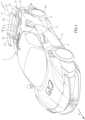
Figure 1 is a schematic perspective view, with parts removed for clarity, of a preferred embodiment of the sports vehicle of the present invention; -
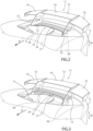
Figures 2 and 3 are two schematic perspective views, with parts removed for clarity, of a detail of the sports vehicle ofFigure 1 illustrated in two different operating positions; and -
Figure 4 is a schematic perspective view, with parts removed for clarity, of a variation of the detail ofFigures 2 and 3 . - With reference to
Figures 1 ,2, and 3 , reference numeral 1 indicates, as a whole, a sports vehicle comprising asupport frame 2 defining at least part of abottom floor 3 of the sports vehicle 1, apassenger compartment 4 mounted on theframe 2 and projecting upwards from thefloor 3, and anouter body 5. - The sports vehicle 1 further comprises a power engine 6 of known type, which is mounted in the centre of a
rear zone 7 of theframe 2, in particular parallel to a forward movingdirection 8 of the sports vehicle 1, is arranged under arear hood 9 of thebody 5, and is connected in a known manner to tworear drive wheels 10 of the sports vehicle 1. - The sports vehicle 1 is further provided with a fixed
rear spoiler 11, which is mounted in the area of thezone 7, extends above thebody 5, and comprises anairfoil 12 extending transversal to thedirection 8, and a pair ofsupport plates 13 for connecting theairfoil 12 to thebody 5. - The
plates 13 are connected in intermediate points of theairfoil 12, which comprises acentral portion 14 extending between the twoplates 13 and twoside portions 15 obtained on opposite sides of theportion 14 and on the outside of theplates 13. - The
portion 14 has a width, measured parallel to thedirection 8, substantially constant and smaller than the width of theportions 15, this too measured parallel to thedirection 8 in the area of theplates 13. - The sports vehicle 1 is further provided with a movable
rear spoiler 16 comprising anairfoil 17, which is mounted between the twoplates 13, and is staggered relative to theportion 14 of theairfoil 12 in thedirection 8. In other words, thespoiler 11, in this case theportion 14, and thespoiler 16, in this case theairfoil 17, do not overlap each other in adirection 18 transversal to thedirection 8 and substantially perpendicular to the road surface (not shown). - The
spoiler 16 is movable, under the thrust of anoperating device 19, between a lifted position (Figure 2 ), in which theairfoil 17 is substantially coplanar to thebody 5, and a lowered position (Figure 3 ), in which theairfoil 17 is arranged under thebody 5. - The
device 19 comprises, in this case, twoelectric motors 20, which are accommodated under thebody 5, are fixed to theframe 2, and have respective output rods connected to thespoiler 16. - When the
spoiler 16 is arranged in its lifted position, thespoilers spoiler 11 and of the aerodynamic drag of thespoiler 16. - When the
spoiler 16 is arranged in its lowered position, thespoilers spoiler 11 and of the vertical load of thespoiler 16. - Furthermore, since the
portion 14 and theairfoil 17 do not overlap each other in thedirection 18, the vertical load exerted by thespoiler 11 on theelectric motors 20 of thespoiler 16 is relatively low and theelectric motors 20 are relatively simple, light and cost-effective. - The variation shown in
Figure 4 , not being part of the present invention, differs from what shown in the previous figures due to the fact that, in said variation, the fixedrear spoiler 11 is eliminated and replaced by a fixedrear spoiler 21, which is mounted in the area of thezone 7, extends above thebody 5, and comprises anairfoil 22 transversal to thedirection 8 and a pair ofsupport plates 23 for connecting theairfoil 22 to thebody 5. - The fixed
rear spoiler 21 and the movablerear spoiler 16 overlap each other in thedirection 18 and theairfoil 22 has a substantially constant width, measured parallel to thedirection 8. - Since the fixed
rear spoiler 21 and the movablerear spoiler 16 overlap each other in the direction 18: - the lifted position of the movable
rear spoiler 16 guarantees a relatively low aerodynamic drag smaller than that obtained with the fixedrear spoiler 11; and - the vertical load exerted by the
spoiler 21 on theelectric motors 20 of thespoiler 16 is relatively high and entails the utilization ofelectric motors 20 having weight and dimensions greater than those of theelectric motors 20 utilized with the fixedrear spoiler 11. - According to a variation not shown, not being part of the present invention, the
spoilers
Claims (9)
- A sports vehicle comprising a support frame (2); a passenger compartment (4); an outer body (5); a fixed rear spoiler (11; 21); a movable rear spoiler (16); and an operating device (19) to move the movable rear spoiler (16) between a lifted position and a lowered position; and characterized in that the fixed rear spoiler (11) and the movable rear spoiler (16) are staggered relative to each other in a forward moving direction (8) of the sports vehicle and that the movable rear spoiler (16) is substantially coplanar to the outer body (5) when arranged in its lifted position and extends under the outer body (5) when arranged in its lowered position.
- The sports vehicle according to claim 1, wherein the fixed rear spoiler (11; 21) comprises an airfoil (12; 22) and a pair of supports (13; 23) to couple the airfoil (12; 22) to a body (5) of the sports vehicle.
- The sports vehicle according to claim 2, wherein the supports (13; 23) are connected in intermediate points of the airfoil (12; 22).
- The sports vehicle according to claim 3, wherein the movable rear spoiler (16) is mounted between the two supports (13).
- The sports vehicle according to claim 3 or 4, wherein the airfoil (12) comprises a central portion (14) extending between the two supports (13) and two side portions (15) obtained on opposite sides of the central portion (14) and on the outside of the supports (13).
- The sports vehicle according to claim 5, wherein the central portion (14) of the airfoil (12) and the movable rear spoiler (16) are staggered relative to each other in said forward moving direction (8).
- The sports vehicle according to claim 5 or 6, wherein the central portion (14) has a width, measured parallel to said forward moving direction (8), which is smaller than a width of a side portion (15) measured parallel to the forward moving direction (8) in the area of the relative support (13).
- The sports vehicle according to any one of the preceding claims, wherein the operating device (19) comprises at least one electric motor (20).
- The sports vehicle according to any one of the preceding claims, wherein the fixed rear spoiler (11) and the movable rear spoiler (16) do not overlap each other in a direction (18) substantially transversal to said forward moving direction (8).
Applications Claiming Priority (1)
| Application Number | Priority Date | Filing Date | Title |
|---|---|---|---|
| IT102023000012405A IT202300012405A1 (en) | 2023-06-16 | 2023-06-16 | SPORTS VEHICLE WITH DOUBLE WING |
Publications (1)
| Publication Number | Publication Date |
|---|---|
| EP4477506A1 true EP4477506A1 (en) | 2024-12-18 |
Family
ID=88097409
Family Applications (1)
| Application Number | Title | Priority Date | Filing Date |
|---|---|---|---|
| EP24181287.4A Pending EP4477506A1 (en) | 2023-06-16 | 2024-06-11 | Sports vehicle with double spoiler |
Country Status (3)
| Country | Link |
|---|---|
| US (1) | US20240417007A1 (en) |
| EP (1) | EP4477506A1 (en) |
| IT (1) | IT202300012405A1 (en) |
Families Citing this family (1)
| Publication number | Priority date | Publication date | Assignee | Title |
|---|---|---|---|---|
| USD1086964S1 (en) * | 2023-10-23 | 2025-08-05 | Mazda Motor Corporation | Motor vehicle |
Citations (3)
| Publication number | Priority date | Publication date | Assignee | Title |
|---|---|---|---|---|
| US6170904B1 (en) * | 1997-06-05 | 2001-01-09 | Dr. Ing. H.C.F. Porsche Ag | Motor vehicle with a rear-mounted air guide device |
| DE102012111849A1 (en) * | 2012-12-05 | 2014-06-05 | Dr. Ing. H.C. F. Porsche Aktiengesellschaft | Tail-air guiding device for motor vehicle, has holding device which is arranged in area of tail of vehicle body of motor vehicle, where holding device is connected with flow profile over extension arrangement |
| DE102019103451B3 (en) * | 2019-02-12 | 2020-06-18 | Dr. Ing. H.C. F. Porsche Aktiengesellschaft | Rear air guiding device |
Family Cites Families (5)
| Publication number | Priority date | Publication date | Assignee | Title |
|---|---|---|---|---|
| DE4441592C2 (en) * | 1994-11-11 | 1999-09-02 | Porsche Ag | Air control device |
| US5863090A (en) * | 1995-07-17 | 1999-01-26 | Georgia Tech Research Corporation | Pneumatic aerodynamic force-augmentation, control and drag-reduction devices for racing cars and high-performance sports cars |
| DE102020117282B4 (en) * | 2020-07-01 | 2024-03-28 | Dr. Ing. H.C. F. Porsche Aktiengesellschaft | Rear air deflector, method for operating a rear air deflector and motor vehicle |
| US20240075994A1 (en) * | 2021-01-25 | 2024-03-07 | Lotus Tech Innovation Centre Gmbh | Spoiler system for a vehicle |
| IT202200015267A1 (en) * | 2022-07-20 | 2024-01-20 | Ferrari Spa | MOVING WING GROUP FOR A ROAD VEHICLE, METHOD OF CONTROLLING A MOVING WING FOR A ROAD VEHICLE AND RELATED ROAD VEHICLE |
-
2023
- 2023-06-16 IT IT102023000012405A patent/IT202300012405A1/en unknown
-
2024
- 2024-06-06 US US18/735,714 patent/US20240417007A1/en active Pending
- 2024-06-11 EP EP24181287.4A patent/EP4477506A1/en active Pending
Patent Citations (3)
| Publication number | Priority date | Publication date | Assignee | Title |
|---|---|---|---|---|
| US6170904B1 (en) * | 1997-06-05 | 2001-01-09 | Dr. Ing. H.C.F. Porsche Ag | Motor vehicle with a rear-mounted air guide device |
| DE102012111849A1 (en) * | 2012-12-05 | 2014-06-05 | Dr. Ing. H.C. F. Porsche Aktiengesellschaft | Tail-air guiding device for motor vehicle, has holding device which is arranged in area of tail of vehicle body of motor vehicle, where holding device is connected with flow profile over extension arrangement |
| DE102019103451B3 (en) * | 2019-02-12 | 2020-06-18 | Dr. Ing. H.C. F. Porsche Aktiengesellschaft | Rear air guiding device |
Also Published As
| Publication number | Publication date |
|---|---|
| US20240417007A1 (en) | 2024-12-19 |
| IT202300012405A1 (en) | 2024-12-16 |
Similar Documents
| Publication | Publication Date | Title |
|---|---|---|
| US8740285B2 (en) | Vehicle airfoils for safety, efficiency, and performance | |
| US6230836B1 (en) | Aerodynamic automobile | |
| EP2802469B1 (en) | Fairing for a truck cab-trailer gap | |
| EP2631160B1 (en) | A rear spoiler with adjustable aerodynamic profiles for a high performance road vehicle | |
| EP4477506A1 (en) | Sports vehicle with double spoiler | |
| US10246141B2 (en) | Variable-width aerodynamic spoiler assemblies and control logic for motor vehicles | |
| US10384730B2 (en) | Electronic active air dam | |
| JP7498628B2 (en) | Vehicles with rear spoiler and movable deflector panel to adjust rear spoiler movement | |
| WO2018009442A1 (en) | System for repositioning weight in response to vehicle speed | |
| EP3792161B1 (en) | Car provided with a rear spoiler and with aerodynamic elements to increase the aerodynamic efficiency of the rear spoiler | |
| US20160339972A1 (en) | Streamlining stabilizers for the undersides of vehicles | |
| CN110294027B (en) | Bottom channel vortex generator | |
| CN119773878A (en) | Vehicle front structure | |
| JP7397020B2 (en) | vehicle | |
| CN111386204B (en) | battery case | |
| CN112896344A (en) | Active backplate shunt and engine shroud | |
| US11919578B2 (en) | Movable wing/aerofoil assembly | |
| CN109204585A (en) | Automotive aerodynamics body bottom device | |
| EP3793888B1 (en) | Twist beam air guided tunnel diffuser | |
| WO2012118505A1 (en) | Adjustable fifth wheel hitch assembly | |
| KR100222085B1 (en) | Flying car | |
| CN223919395U (en) | A front-wheel drive subframe with a collapsible energy-absorbing box | |
| KR101438936B1 (en) | Active retractable spoiler for vehicle | |
| CA2233001C (en) | Automobile | |
| CN120697471A (en) | Wheels and vehicles |
Legal Events
| Date | Code | Title | Description |
|---|---|---|---|
| PUAI | Public reference made under article 153(3) epc to a published international application that has entered the european phase |
Free format text: ORIGINAL CODE: 0009012 |
|
| STAA | Information on the status of an ep patent application or granted ep patent |
Free format text: STATUS: THE APPLICATION HAS BEEN PUBLISHED |
|
| AK | Designated contracting states |
Kind code of ref document: A1 Designated state(s): AL AT BE BG CH CY CZ DE DK EE ES FI FR GB GR HR HU IE IS IT LI LT LU LV MC ME MK MT NL NO PL PT RO RS SE SI SK SM TR |
|
| STAA | Information on the status of an ep patent application or granted ep patent |
Free format text: STATUS: REQUEST FOR EXAMINATION WAS MADE |
|
| 17P | Request for examination filed |
Effective date: 20250617 |
|
| STAA | Information on the status of an ep patent application or granted ep patent |
Free format text: STATUS: EXAMINATION IS IN PROGRESS |
|
| 17Q | First examination report despatched |
Effective date: 20251009 |