EP4477480A1 - Lock catch and vehicle - Google Patents
Lock catch and vehicle Download PDFInfo
- Publication number
- EP4477480A1 EP4477480A1 EP22947327.7A EP22947327A EP4477480A1 EP 4477480 A1 EP4477480 A1 EP 4477480A1 EP 22947327 A EP22947327 A EP 22947327A EP 4477480 A1 EP4477480 A1 EP 4477480A1
- Authority
- EP
- European Patent Office
- Prior art keywords
- buckle
- state
- button
- lock catch
- locking tongue
- Prior art date
- Legal status (The legal status is an assumption and is not a legal conclusion. Google has not performed a legal analysis and makes no representation as to the accuracy of the status listed.)
- Pending
Links
Images




Classifications
-
- B—PERFORMING OPERATIONS; TRANSPORTING
- B60—VEHICLES IN GENERAL
- B60R—VEHICLES, VEHICLE FITTINGS, OR VEHICLE PARTS, NOT OTHERWISE PROVIDED FOR
- B60R22/00—Safety belts or body harnesses in vehicles
- B60R22/48—Control systems, alarms, or interlock systems, for the correct application of the belt or harness
-
- A—HUMAN NECESSITIES
- A44—HABERDASHERY; JEWELLERY
- A44B—BUTTONS, PINS, BUCKLES, SLIDE FASTENERS, OR THE LIKE
- A44B11/00—Buckles; Similar fasteners for interconnecting straps or the like, e.g. for safety belts
- A44B11/25—Buckles; Similar fasteners for interconnecting straps or the like, e.g. for safety belts with two or more separable parts
- A44B11/2503—Safety buckles
- A44B11/2507—Safety buckles actuated by a push-button
- A44B11/2523—Safety buckles actuated by a push-button acting parallel to the main plane of the buckle and in the same direction as the fastening action
-
- B—PERFORMING OPERATIONS; TRANSPORTING
- B60—VEHICLES IN GENERAL
- B60R—VEHICLES, VEHICLE FITTINGS, OR VEHICLE PARTS, NOT OTHERWISE PROVIDED FOR
- B60R22/00—Safety belts or body harnesses in vehicles
- B60R22/18—Anchoring devices
- B60R22/26—Anchoring devices secured to the seat
-
- A—HUMAN NECESSITIES
- A44—HABERDASHERY; JEWELLERY
- A44B—BUTTONS, PINS, BUCKLES, SLIDE FASTENERS, OR THE LIKE
- A44B11/00—Buckles; Similar fasteners for interconnecting straps or the like, e.g. for safety belts
- A44B11/25—Buckles; Similar fasteners for interconnecting straps or the like, e.g. for safety belts with two or more separable parts
- A44B11/2503—Safety buckles
- A44B11/2546—Details
- A44B11/2565—Illuminated buckles
-
- B—PERFORMING OPERATIONS; TRANSPORTING
- B60—VEHICLES IN GENERAL
- B60R—VEHICLES, VEHICLE FITTINGS, OR VEHICLE PARTS, NOT OTHERWISE PROVIDED FOR
- B60R22/00—Safety belts or body harnesses in vehicles
- B60R22/18—Anchoring devices
- B60R2022/1806—Anchoring devices for buckles
-
- B—PERFORMING OPERATIONS; TRANSPORTING
- B60—VEHICLES IN GENERAL
- B60R—VEHICLES, VEHICLE FITTINGS, OR VEHICLE PARTS, NOT OTHERWISE PROVIDED FOR
- B60R22/00—Safety belts or body harnesses in vehicles
- B60R22/48—Control systems, alarms, or interlock systems, for the correct application of the belt or harness
- B60R2022/4866—Displaying or indicating arrangements thereof
Definitions
- the present application relates to the technical field of vehicles, and in particular to a lock catch and a vehicle.
- the buckle return spring 400 will drive the buckle 300 to switch from the second state to the first state to prepare for the locking tongue 950 to be inserted into the inserting groove 200a again, and the locking tongue 950 can be buckled with the buckle portion 300b again.
- the first direction is the A direction indicated in FIG. 1 and FIG. 4 .
- the buckle 300 and the transmission member 320 are separate components.
- the transmission member 320 is penetrated in the buckle 300, and exceeds the two sides of the buckle 300 in the extending direction of the rotating shaft 310.
- the two exceeding parts are two transmission portions 320a respectively.
- Separately manufacturing the transmission member 320 and the buckle 300 is conducive to reducing the difficulty of manufacturing the buckle 300 and the transmission seat as a whole.
- the transmission member in order to improve the structural strength of the buckle and the transmission member as a whole, the transmission member is connected to the buckle as a whole.
- the lock catch 100 further includes a rotating shaft 310 corresponding to the inserting groove 200a, and the buckle 300 is rotatably connected to the base seat 200 via the rotating shaft 310.
- the transmission spring 600 includes a first torsion spring 610, and the first torsion spring 610 includes a first spring body 611 sleeved on the rotating shaft 310, and a first torsion arm 612 and a second torsion arm 613 respectively connected to both ends of the first spring body 611.
- the transmission spring can also be configured as a pressing spring. In order to prevent the pressing spring from moving when the button is pressed, and a guide column is provided on the side of the buckle close to the button for the pressing spring to be sleeved.
- the transmission spring can also be configured as a spring sheet, and the transmission spring is bent towards the button.
- the lock catch 100 further includes a rotating shaft 310 corresponding to the inserting groove 200a
- the buckle 300 is rotatably connected to the base seat 200 via the rotating shaft 310
- the buckle return spring 400 includes a second torsion spring 410
- the second torsion spring 410 includes a second spring body 411 sleeved on the rotating shaft 310
- a third torsion arm 412 and a fourth torsion arm 413 respectively connected to both ends of the second spring body 411.
- the third torsion arm 412 is connected to the base seat 200
- the fourth torsion arm 413 is abutted against a side of the buckle 300 away from the button 500.
- the cooperation between the second torsion spring 410, the rotating shaft 310, and the buckle 300 is simple and easy to realize.
- the rotating shaft 310 also cooperates with the second spring body 411 to prevent the second spring body 411 from being separated from the rotating shaft 310 and causing the fourth torsion arm 413 to be separated from the buckle 300.
- the transmission spring can also be configured as a pressing spring. One end of the transmission spring is connected to the side of the buckle away from the button, and the other end of the transmission spring is connected to the base seat, as long as the transmission spring can drive the buckle to switch from the second state to the first state.
- the transmission spring can also be configured as a tension spring. One end of the transmission spring is connected to the side of the buckle close to the button, and the other end of the transmission spring is connected to the base seat, as long as the transmission spring can drive the buckle to switch from the second state to the first state.
- the lock catch 100 further includes a locking tongue return spring 700 configured for the locking tongue 950 to press along the first direction, and the locking tongue return spring 700 is provided in the inserting groove 200a.
- the locking tongue return spring 700 has elastic potential energy to drive the locking tongue 950 to withdraw from the inserting groove 200a.
- the buckle portion 300b is released from the buckle hole 950a buckled with the locking tongue 950, the locking tongue 950 moves in a direction opposite to the first direction under the action of the locking tongue return spring 700, so that the user can pull the locking tongue 950 out of the lock catch 100.
- the lock catch 100 further includes a circuit box 800.
- the circuit box 800 includes a box body 810 configured to be electrically connected to an indicator light, and a triggering member 820 elastically connected to the box body 810.
- the triggering member 820 is configured for the locking tongue 950 to abut against.
- the circuit box 800 has a conductive state and an off state.
- the locking tongue 950 is abutted against the triggering member 820 of the circuit box 80 in the conductive state, and the triggering member 820 moves to the outside of the inserting groove 200a, so that the circuit box 800 is switched to the off state.
- the buckle 300 is in the first state, that is, the buckle portion 300 is buckled with the buckle hole 950a of the locking tongue 950, and the indicator light is off, indicating that the passenger has fastened the safety belt.
- the circuit box 800 Since the triggering member 820 is elastically connected to the box body 810, the circuit box 800 has a tendency to switch from the off state to the conductive state, and the triggering member 820 presses the locking tongue 950 without entering the inserting groove 200a, which ensures that the indicator light is off, so that the driver can judge whether the indicator light is on to know whether the passenger has fastened the safety belt.
- the indicator light can be set on the dashboard of the vehicle for the driver to watch, and of course the indicator light can also be set on the display.
- the triggering member 820 includes a contact point 822 elastically retracted from the box body 810, and an elastic sheet 821 connected to the box body 810.
- the elastic sheet 821 is tilted along the first direction in the direction in which the box body 810 is close to the inserting groove 200a, and the contact point 822 is provided between the box body 810 and the elastic sheet 821.
- the elastic sheet 821 is configured for pressing the contact point 822, and the elastic sheet 821 is configured to be pressed by the locking tongue 950.
- the elastic sheet 821 In the conductive state, the elastic sheet 821 extends into the inserting groove 200a, and the elastic sheet 821 is abutted against the contact point 822; in the off state, the elastic sheet 821 is located outside the inserting groove 200a, the elastic sheet 821 is abutted against the contact point 822, and the locking tongue 950 can be abutted against the elastic sheet 821 to switch the circuit box 800 from the conductive state to the off state. In this way, the elastic sheet 821 shares the force of the locking tongue 950 acting on the contact point 822, thereby protecting the contact point 822.
- the triggering member can be configured only as a contact point, as long as the structural strength of the contact point is high enough.
- the button 500 is configured as a light-transmitting member.
- the lock catch 100 further includes a light source 910, and the button 500 and the light source 910 are provided in sequence in the pressing direction of the button 500.
- the button 500 does not block the light emitted by the light source 910, and the human eye can see the light emitted by the lock catch 100, so that it is convenient for passengers to find the lock catch 100 in a low-brightness environment, and it is convenient for passengers to buckle the lock catch 100 with the locking tongue 950.
- it is also convenient for passengers to find the position of the button 500 so that it is convenient for passengers to press the button 500 to release the buckle between the lock catch 100 and the locking tongue 950.
- the material of the button 500 includes PC material, which has high transparency. In another embodiment, the material of the button includes PP material.
- a logo layer 920 is provided on a side of the button 500 away from the light source 910.
- the logo layer 920 is more eye-catching under the illumination of the light source 910.
- the logo layer 920 can be an image that the user likes to improve the user experience.
- the logo layer 920 can also be a brand's logo to improve the brand's popularity.
- the material of the logo layer 920 includes a fluorescent material, so that the logo layer 920 is more eye-catching under the illumination of the light source 910.
- the material of the logo layer includes metal, so that the logo will show a metallic luster under the illumination of the light source.
- the light source 910 is fixed to the button 500. In this way, the relative position of the light source 910 and the button 500 will not change, thereby ensuring that the light source 910 can give the logo layer 920 a better display effect during the movement of the button 500.
- the button is fixed to the base seat to reduce the force required when the button returns to its original position.
- the lock catch 100 further includes a light guiding member 940, and the light source 910 is fixed to the button 500 through the light guiding member 940. In this way, the light generated by the light source 910 is collected by the light guiding member 940, so that the lock catch 100 appears brighter and more eye-catching, which is more conducive to passengers finding the lock catch 100.
- the light source 910, the light guiding member 940 and the button 500 are fixed by screw locking.
- the light source, the light guiding member, and the button are snap-fitted.
- the light source, the light guiding member, and the button are bonded.
Landscapes
- Engineering & Computer Science (AREA)
- Mechanical Engineering (AREA)
- Automation & Control Theory (AREA)
- Automotive Seat Belt Assembly (AREA)
- Buckles (AREA)
Abstract
Description
- The present application relates to the technical field of vehicles, and in particular to a lock catch and a vehicle.
- The vehicle includes a lock catch, a locking tongue buckled with the lock catch, and a safety belt connected to the locking tongue. To ensure the safety of the passenger, the passenger needs to wear the safety belt during the driving of the vehicle, that is, the locking tongue is buckled with the lock catch. However, the unlocking process of the lock catch in the exemplary structure is not smooth enough.
- The purpose of the present application is to provide a lock catch, aiming to improve the smoothness of the unlocking process of the lock catch.
- To achieve the above purpose, the lock catch provided in the present application includes:
- a base seat provided with an inserting groove extending in a first direction, the inserting groove is configured for a locking tongue to be inserted in the first direction, and the locking tongue is provided with a buckle hole;
- a buckle corresponding to the inserting groove, the buckle is rotatably connected to the base seat to have a first state and a second state, the buckle is provided with a buckle portion configured to be buckled with the buckle hole, and the buckle portion is further configured to be abutted against the locking tongue; in the first state, the buckle portion is configured to extend into the inserting groove; and in the second state, the buckle portion is outside the inserting groove, and the locking tongue is abutted against the buckle to switch the buckle from the first state to the second state;
- a buckle return spring provided between the buckle and the base seat, the buckle return spring is configured to drive the buckle to switch from the second state to the first state;
- a transmission member connected to the buckle, the transmission member includes two transmission portions provided on both sides of the buckle along a rotation direction of the buckle; and
- a button movably provided on the base seat, the button is provided with two abutting surfaces respectively towards the two transmission portions, one of the abutting surfaces is configured to be abutted against one of the transmission portions, and the button is configured to drive the buckle from the first state to the second state along the first direction through the transmission member.
- In an embodiment, the abutting surface is recessed in a direction away from the corresponding transmission portion, and a normal direction where the abutting surface is abutted against the corresponding transmission portion during the process of the abutting surface abutting against the corresponding transmission portion is a tangent direction of a rotation of the transmission member around a rotating shaft.
- In an embodiment, the lock catch further includes: a transmission spring provided between the buckle and the button, and the button is also indirectly abutted against the buckle by pressing the transmission spring along the first direction.
- In an embodiment, the lock catch further includes: a rotating shaft corresponding to the inserting groove, and the buckle is rotatably connected to the base seat through the rotating shaft, the transmission spring includes a first torsion spring, the first torsion spring includes a first spring body sleeved on the rotating shaft, and a first torsion arm and a second torsion arm respectively connected to both ends of the first spring body, the first torsion arm is connected to the base seat, the second torsion arm is abutted against one side of the buckle close to the button, the second torsion arm is bent from the buckle towards the button, and the button is configured to press the second torsion arm along the first direction.
- In an embodiment, two first torsion springs are provided on both sides of the buckle in an extending direction of the rotating shaft, and two second torsion arms are connected to each other as a whole.
- In an embodiment, the lock catch further includes: a rotating shaft corresponding to the inserting groove, and the buckle is rotatably connected to the base seat through the rotating shaft, the buckle return spring includes a second torsion spring, the second torsion spring includes a second spring body sleeved on the rotating shaft, and a third torsion arm and a fourth torsion arm respectively connected to both ends of the second spring body, the third torsion arm is connected to the base seat, and the fourth torsion arm is abutted against one side of the buckle away from the button.
- In an embodiment, two second torsion springs are respectively provided on both sides of the buckle in an extending direction of the rotating shaft, and two fourth torsion arms are connected to each other as a whole.
- In an embodiment, a limiting groove configured to be engaged with the fourth torsion arm is provided on the side of the buckle away from the button.
- In an embodiment, the lock catch further includes: a locking tongue return spring configured for the locking tongue to press along the first direction, and the locking tongue return spring is provided in the inserting groove.
- In an embodiment, the locking tongue return spring is configured as a spring sheet, the locking tongue return spring is configured to protrude in a direction opposite to the first direction, and both ends of the locking tongue return spring are connected to the base seat.
- In an embodiment, the lock catch further includes:
- a circuit box, and
- the circuit box includes a box body configured to be electrically connected to an indicator light, and a triggering member elastically connected to the box body; the triggering member is configured to be abutted against the locking tongue, and the circuit box has a conductive state and an off state; in the conductive state, the triggering member is configured to extend into the inserting groove, and the box body and the indicator light are conductive; in the off state, the triggering member is outside the inserting groove, the box body is disconnected from the indicator light, the locking tongue is abutted against the circuit box to switch from the conductive state to the off state, and in response to that the circuit box is in the off state, the buckle is in the first state.
- In an embodiment, the triggering member includes a contact point elastically retracted on the box body and an elastic sheet connected to the box body, the elastic sheet is provided obliquely along the first direction in a direction of the box body close to the inserting groove, the contact point is provided between the box body and the elastic sheet, the elastic sheet is configured to press the contact point, and the elastic sheet is configured to be pressed by the locking tongue; in the conductive state, the elastic sheet is configured to extend into the inserting groove, and the elastic sheet is abutted against the contact point; and in the off state, the elastic sheet is outside the inserting groove, the elastic sheet is abutted against the contact point, and the locking tongue is abutted against the elastic sheet to switch the circuit box from the conductive state to the off state.
- In an embodiment, the button is configured as a light-transmitting member, the lock catch further includes a light source, and the button and the light source are provided in sequence in a pressing direction of the button.
- In an embodiment, a logo layer is provided on one side of the button away from the light source.
- In an embodiment, the lock catch further includes: a light-transmitting protective shell covered on the logo layer.
- In an embodiment, the light source is fixed to the button.
- In an embodiment, the lock catch further includes: a light guiding member, and
the light source is fixed to the button through the light guiding member. - The present application also provides a vehicle, including the lock catch.
- In the technical solution of the present application, the locking tongue can be inserted into the inserting groove along the first direction. During the insertion process, the locking tongue is abutted against the buckle portion of the buckle located in the first state, that is, abutted against the buckle portion located in the inserting groove. The buckle portion rotates around the rotating axis of the buckle, so that the buckle portion moves to the outside of the inserting groove, thereby switching the buckle to the second state. Then the locking tongue continues to move along the first direction. At this time, the buckle has a tendency to switch from the second state to the first state under the action of the buckle return spring. Under the action of the buckle return spring, the buckle makes the buckle portion press against the surface of the locking tongue and slide relatively. Until the buckle portion is corresponding to the buckle hole of the locking tongue, the buckle makes the buckle portion extend into the buckle hole and buckled with the buckle hole under the action of the buckle return spring. It can be understood that at this time, the buckle portion extends into the inserting groove, and the buckle switches from the second state to the first state under the action of the buckle return spring, so that the lock catch is buckled with the locking tongue, and the passenger finishes wearing the safety belt. When the passenger wants to unlock the safety belt, he can press the button so that the abutting surface of the button is abutted against the transmission portion to drive the buckle to rotate. Since the transmission portion is provided on both sides of the buckle in the extension direction of the rotating shaft, the buckle can smoothly switch from the first state to the second state when the two abutting surfaces are respectively abutted against the two transmission portions, thereby improving the smoothness of the unlocking process of the lock catch. In the second state, the buckle portion is located outside the inserting groove, so that the lock catch is unlocked, and the locking tongue can be separated from the inserting groove without the action of the buckle portion. It can be understood that after releasing the button, the buckle return spring will drive the buckle to switch from the second state to the first state, so that the locking tongue can be inserted into the inserting groove again and the locking tongue can be buckled with the buckle portion again.
- In order to illustrate the technical solutions in the embodiments of the present application or in the related art more clearly, the following briefly introduces the accompanying drawings required for the description of the embodiments or the related art. Obviously, the drawings in the following description are only part of embodiments of the present application. For those skilled in the art, other drawings can also be obtained according to the structures shown in these drawings without any creative effort.
-
FIG. 1 is a schematic structural view of a lock catch buckled with a locking tongue according to an embodiment of the present application. -
FIG. 2 is an exploded view of the lock catch and the locking tongue inFIG. 1 . -
FIG. 3 is a top view of a base seat, a locking tongue return spring, a circuit box, a buckle, a transmission spring, a buckle return spring, a rotating shaft, a transmission member, a button, and a protective shell inFIG. 2 . -
FIG. 4 is a cross-sectional view along B-B inFIG. 3 . -
FIG. 5 is a schematic cooperative structural view of the base seat, the buckle, the transmission spring, the buckle return spring, the rotating shaft, and the transmission member inFIG. 2 . -
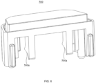
FIG. 6 is a schematic structural view of a button inFIG. 2 . -
FIG. 7 is a schematic cooperative structural view of the buckle, the rotating shaft, and the transmission member inFIG. 2 . -
FIG. 8 is a schematic structural view of the transmission spring inFIG. 2 . -
FIG. 9 is a schematic structural view of the buckle return spring inFIG. 2 . -
FIG. 10 is a schematic cooperative structural view of the base seat and the locking tongue return spring inFIG. 2 . -
FIG. 11 is a schematic cooperative structural view of the base seat and the circuit box inFIG. 2 . -
Reference sign Name Reference sign Name 100 lock catch 520 fixing seat 200 base seat 600 transmission spring 200a inserting groove 610 first torsion spring 220b avoiding groove 611 first spring body 300 buckle 612 first torsion arm 300a limiting groove 613 second torsion arm 300b buckle portion 700 locking tongue return spring 310 rotating shaft 800 circuit box 320 transmission member 810 box body 320a transmission portion 820 triggering member 400 buckle return spring 821 elastic sheet 410 second torsion spring 822 contact point 411 second spring body 910 light source 412 third torsion arm 920 logo layer 413 fourth torsion arm 930 protective shell 413a first section 940 light guiding member 413b second section 950 locking tongue 500 button 950a buckle hole 500a abutting surface 960 casing 510 button return spring - The realization of the objective, functional characteristics, and advantages of the present application are further described with reference to the accompanying drawings.
- The technical solutions of the embodiments of the present application will be described in more detail below with reference to the accompanying drawings. It is obvious that the embodiments to be described are only some rather than all of the embodiments of the present application. All other embodiments obtained by those skilled in the art based on the embodiments of the present application without creative efforts shall fall within the scope of the present application.
- It should be noted that all directional indications (such as up, down, left, right, front, back, etc.) in the embodiments of the present application are only used to explain the relative positional relationship, the movement situation, etc. If the specific posture changes, the directional indication also changes accordingly.
- In the present application, unless otherwise specified and limited, the terms "connecting" and "fixing" should be understood in a broad sense, for example, it can be a fixed connection, a detachable connection, integrally connected, mechanically connected, electrically connected, directly connected or indirectly connected through an intermediary, and it can be the internal connectivity of two components or the interaction between two components, unless otherwise limited. Those skilled in the art can understand the specific meanings of the above terms in the present application according to specific situations.
- In addition, the descriptions of "first", "second", etc. are only for the purpose of description, and should not be construed as indicating or implying relative importance or implicitly indicates the number of technical features indicated. Thus, a feature delimited with "first", "second" may expressly or implicitly include at least one of that feature. In addition, the meaning of "and/or" in the present application includes three parallel schemes, taking "A and/or B" as an example, including scheme A, or scheme B, or scheme A and B at the same time. In addition, the technical solutions between the various embodiments can be combined with each other, but must be based on the realization by those skilled in the art. When the combination of technical solutions is contradictory or cannot be realized, it should be considered that the combination of such technical solutions does not exist or fall within the scope of protection claimed in the present application.
- The vehicle includes a lock catch, a locking tongue buckled with the lock catch, and a safety belt connected to the locking tongue. To ensure the safety of the passenger, the passenger needs to wear the safety belt during the driving of the vehicle, that is, the locking tongue is buckled with the lock catch. However, the unlocking process of the lock catch in the exemplary structure is not smooth enough. Therefore, the present application provides a lock catch, improving the smoothness of the unlocking process of the lock catch.
- Referring to
FIG. 1 to 7 , in an embodiment of the present application, thelock catch 100 includes: abase seat 200, abuckle 300, abuckle return spring 400, atransmission member 320 andbutton 500. - The
base seat 200 is provided with an insertinggroove 200a extending along a first direction, the insertinggroove 200a is configured for the lockingtongue 950 to be inserted along the first direction, and the lockingtongue 950 is provided with abuckle hole 950a. - The
buckle 300 is provided corresponding to the insertinggroove 200a, thebuckle 300 is rotatably connected to thebase seat 200 to have a first state and a second state, thebuckle 300 is provided with abuckle portion 300b configured to be buckled with thebuckle hole 950a, thebuckle portion 300b is also configured to be abutted against the lockingtongue 950. When in the first state, thebuckle portion 300b extends into the insertinggroove 200a; when in the second state, thebuckle portion 300b is outside the insertinggroove 200a, and the lockingtongue 950 can be abutted against thebuckle 300 to switch from the first state to the second state. - The
buckle return spring 400 is provided between thebuckle 300 and thebase seat 200, thebuckle return spring 400 is configured to drive thebuckle 300 to switch from the second state to the first state. - The
transmission member 320 is connected to thebuckle 300, thetransmission member 320 includes twotransmission portions 320a provided on both sides of thebuckle 300 along the rotation direction of thebuckle 300. - The
button 500 is movably provided on thebase seat 200, thebutton 500 is provided with two abuttingsurfaces 500a respectively towards the twotransmission portions 320a, one of the abuttingsurfaces 500a is correspondingly configured to be abutted against one of thetransmission portions 320a, thebutton 500 can drive thebuckle 300 to switch from the first state to the second state via thetransmission member 320 in the first direction. - In the technical solution of the present application, the locking
tongue 950 can be inserted into the insertinggroove 200a along the first direction. During the insertion process, the lockingtongue 950 is abutted against thebuckle portion 300b of thebuckle 300 in the first state, that is, abutted against thebuckle portion 300b located in the insertinggroove 200a. Thebuckle portion 300b rotates around the rotating axis of thebuckle 300, so that thebuckle portion 300b moves to the outside of the insertinggroove 200a, and thebuckle 300 is switched to the second state. Then the lockingtongue 950 continues to move along the first direction. At this time, thebuckle 300 has a tendency to switch from the second state to the first state under the action of thebuckle return spring 400. Thebuckle 300 makes thebuckle portion 300b press against the surface of the lockingtongue 950 and slide relatively under the action of thebuckle return spring 400. Until thebuckle portion 300b is corresponding to thebuckle hole 950a of the lockingtongue 950, thebuckle 300 makes thebuckle portion 300b extend into thebuckle hole 950a and buckled with thebuckle hole 950a under the action of thebuckle return spring 400. It can be understood that at this time, thebuckle portion 300b extends into the insertinggroove 200a, and thebuckle 300 is switched from the second state to the first state under the action of thebuckle return spring 400, so that thelock catch 100 is buckled with the lockingtongue 950, and the passenger completes wearing the safety belt. When the passenger wants to unlock the safety belt, thebutton 500 can be pressed to make theabutting surface 500a of thebutton 500 be abutted against thetransmission portion 320a, thereby driving thebuckle 300 to rotate. Since thetransmission portion 320a is provided on both sides of thebuckle 300 in the extending direction of therotating shaft 310, when the two abuttingsurfaces 500a are respectively abutted against the twotransmission portions 320a, thebuckle 300 can smoothly switch from the first state to the second state, thereby improving the smoothness of the unlocking process of thelock catch 100. In the second state, thebuckle portion 300b is located outside the insertinggroove 200a, so that thelock catch 100 is unlocked, and the lockingtongue 950 can be separated from the insertinggroove 200a without thebuckle portion 300b. It can be understood that when thebutton 500 is released, thebuckle return spring 400 will drive thebuckle 300 to switch from the second state to the first state to prepare for the lockingtongue 950 to be inserted into the insertinggroove 200a again, and the lockingtongue 950 can be buckled with thebuckle portion 300b again. - It should be noted that the first direction is the A direction indicated in
FIG. 1 andFIG. 4 . In addition, in an embodiment, thebuckle 300 and thetransmission member 320 are separate components. Thetransmission member 320 is penetrated in thebuckle 300, and exceeds the two sides of thebuckle 300 in the extending direction of therotating shaft 310. The two exceeding parts are twotransmission portions 320a respectively. Separately manufacturing thetransmission member 320 and thebuckle 300 is conducive to reducing the difficulty of manufacturing thebuckle 300 and the transmission seat as a whole. In another embodiment, in order to improve the structural strength of the buckle and the transmission member as a whole, the transmission member is connected to the buckle as a whole. - In addition, in an embodiment, the
lock catch 100 also includes acasing 960 covered on thebase seat 200, and thecasing 960 includes a plurality of detachable sub-casings. - In order to make the process of pressing the
button 500 less laborious for the passenger, in an embodiment, the abuttingsurface 500a is recessed in a direction away from the correspondingtransmission portion 320a, and the normal direction of the contact point between theabutting surface 500a and the correspondingtransmission portion 320a when the abuttingsurface 500a is abutted against the correspondingtransmission portion 320a is the tangent direction of the rotation of thetransmission member 320 around therotating shaft 310. In this way, the force required for the passenger to press thebutton 500 to drive thebuckle 300 to switch from the first state to the second state is relatively small, which is convenient for the user to make thelock catch 100 buckle with thebuckle 300. In another embodiment, in order to simplify the structure of the button, the abutting surface can be inclined in the first direction along the direction close to the inserting groove, and the abutting surface is a flat plane. - It can be understood that if the
button 500 is pressed at a position closer to one of thetransmission portions 320a in the axial direction of therotating shaft 310, theother transmission portion 320a will be subjected to less force, and it is even possible that the abuttingsurface 500a does not abut against the correspondingtransmission portion 320a, so that thetransmission portion 320a is not subjected to force, which will cause thebuckle 300 to rotate less smoothly. Therefore, in an embodiment, thelock catch 100 further includes atransmission spring 600 provided between thebuckle 300 and thebutton 500, and thebutton 500 is also indirectly abutted against thebuckle 300 by pressing thetransmission spring 600 along the first direction. In this way, thebutton 500 can also indirectly transmit force to thebuckle 300 through thetransmission spring 600, so that the combined force from thebutton 500 on thebuckle 300 is as close to the midpoint between the twotransmission portions 320a as possible. No matter whichtransmission portion 320a thebutton 500 is close to in the axial direction of therotating shaft 310, thebutton 500 can drive thebuckle 300 to rotate relatively smoothly. It is worth mentioning that thetransmission spring 600 has a certain amount of expansion and contraction, so that thebutton 500 will not press thetransmission spring 600 because the pressing point of thebutton 500 is far away from thetransmission spring 600. In addition, after the passenger releases thebutton 500, thetransmission spring 600 can also release the elastic potential energy to promote the reset of thebutton 500. In another embodiment, the transmission spring can be replaced by an elastic member, such as a rubber member. - Referring to
FIG. 8 , there are various specific structures of thetransmission spring 600. For example, in an embodiment, thelock catch 100 further includes arotating shaft 310 corresponding to the insertinggroove 200a, and thebuckle 300 is rotatably connected to thebase seat 200 via therotating shaft 310. Thetransmission spring 600 includes afirst torsion spring 610, and thefirst torsion spring 610 includes afirst spring body 611 sleeved on therotating shaft 310, and afirst torsion arm 612 and asecond torsion arm 613 respectively connected to both ends of thefirst spring body 611. Thefirst torsion arm 612 is connected to thebase seat 200, thesecond torsion arm 613 is abutted against a side of thebuckle 300 close to thebutton 500, thesecond torsion arm 613 is bent from thebuckle 300 towards thebutton 500, and thebutton 500 is configured for pressing thesecond torsion arm 613 along the first direction. In this way, thefirst torsion spring 610, therotating shaft 310, and thebuckle 300 cooperate with each other in a simple and easy manner. In addition to rotating thebuckle 300 relative to thebase seat 200, therotating shaft 310 also cooperates with thefirst spring body 611 to prevent thefirst spring body 611 from being separated from therotating shaft 310 and causing thesecond torsion arm 613 to be separated from thebuckle 300. In another embodiment, the transmission spring can also be configured as a pressing spring. In order to prevent the pressing spring from moving when the button is pressed, and a guide column is provided on the side of the buckle close to the button for the pressing spring to be sleeved. In another embodiment, the transmission spring can also be configured as a spring sheet, and the transmission spring is bent towards the button. - In an embodiment, two first torsion springs 610 are provided, and the two first torsion springs 610 are provided on both sides of the
buckle 300 in the extending direction of therotating shaft 310. The twosecond torsion arms 613 are connected to each other as a whole. By arranging the two first torsion springs 610 on both sides of thebuckle 300, thebuckle 300 can be more evenly stressed when thebutton 500 is abutted against thebuckle 300 by thetransmission spring 600, and thesecond torsion arms 613 are connected to each other as a whole, which can prevent thesecond torsion arm 613 from being overly stressed and causing thesecond torsion arm 613 to be excessively deformed and loosened, thereby extending the service life of thetransmission spring 600. - Referring to
FIG. 9 , there are various structures of thebuckle return spring 400. For example, in an embodiment, thelock catch 100 further includes arotating shaft 310 corresponding to the insertinggroove 200a, thebuckle 300 is rotatably connected to thebase seat 200 via therotating shaft 310, thebuckle return spring 400 includes asecond torsion spring 410, thesecond torsion spring 410 includes asecond spring body 411 sleeved on therotating shaft 310, and athird torsion arm 412 and afourth torsion arm 413 respectively connected to both ends of thesecond spring body 411. Thethird torsion arm 412 is connected to thebase seat 200, and thefourth torsion arm 413 is abutted against a side of thebuckle 300 away from thebutton 500. Thus, the cooperation between thesecond torsion spring 410, therotating shaft 310, and thebuckle 300 is simple and easy to realize. In addition to making thebuckle 300 rotate relative to thebase seat 200, therotating shaft 310 also cooperates with thesecond spring body 411 to prevent thesecond spring body 411 from being separated from therotating shaft 310 and causing thefourth torsion arm 413 to be separated from thebuckle 300. In another embodiment, the transmission spring can also be configured as a pressing spring. One end of the transmission spring is connected to the side of the buckle away from the button, and the other end of the transmission spring is connected to the base seat, as long as the transmission spring can drive the buckle to switch from the second state to the first state. In another embodiment, the transmission spring can also be configured as a tension spring. One end of the transmission spring is connected to the side of the buckle close to the button, and the other end of the transmission spring is connected to the base seat, as long as the transmission spring can drive the buckle to switch from the second state to the first state. - In an embodiment, two second torsion springs 410 are provided, and the two second torsion springs 410 are provided on both sides of the
buckle 300 in the extending direction of therotating shaft 310, and the twofourth torsion arms 413 are connected to each other as a whole. By arranging the two second torsion springs 410 on both sides of thebuckle 300, thebuckle 300 can be subjected to a more uniform force when thebutton 500 is abutted against thebuckle 300 by thebuckle return spring 400, and thefourth torsion arms 413 are connected to each other as a whole, which can prevent thefourth torsion arm 413 from being subjected to excessive force and causing thefourth torsion arm 413 to be excessively deformed and loosened, thereby extending the service life of thebuckle return spring 400. - Referring to
FIG. 7 , in an embodiment, a limitinggroove 300a configured for thefourth torsion arm 413 to engage is provided on a side of thebuckle 300 away from thebutton 500, further preventing thefourth torsion arm 413 from being separated from thebuckle 300. In another embodiment, the buckle is provided with a limiting hole for the fourth torsion arm to pass through. - Referring to
FIG. 9 , in an embodiment, the extending direction of the limitinggroove 300a is parallel to the extending direction of therotating shaft 310, and thefourth torsion arm 413 includes afirst section 413a engaged with the limitinggroove 300a, and asecond section 413b connected to thefirst section 413a at an angle. Thesecond section 413b extends along the groove width direction of the limitinggroove 300a, and the second end limits the movement of thesecond torsion spring 410 along therotating shaft 310. - Referring to
FIG. 5 , in an embodiment, thebase seat 200 is provided with two avoidinggrooves 220b for the twotransmission portions 320a to pass through respectively, so as to prevent thetransmission portions 320a from interfering with thebase seat 200 when rotating around therotating shaft 310. - In order to facilitate the
button 500 to return to its original position, in an embodiment, thelock catch 100 further includes a lockingtongue return spring 510. The lockingtongue return spring 510 is provided between thebase seat 200 and thebutton 500, and is configured for pressing thebutton 500 along the first direction. In addition, in an embodiment, thelock catch 100 further includes a fixingseat 520 connected to thebase seat 200, the lockingtongue return spring 510 is connected to thebase seat 200 through the fixingseat 520, and the fixingseat 520 provides support for the lockingtongue return spring 510. - Referring to
FIG. 10 , in an embodiment, thelock catch 100 further includes a lockingtongue return spring 700 configured for the lockingtongue 950 to press along the first direction, and the lockingtongue return spring 700 is provided in the insertinggroove 200a. When the lockingtongue 950 is inserted into the insertinggroove 200a and presses the lockingtongue return spring 700, the lockingtongue return spring 700 has elastic potential energy to drive the lockingtongue 950 to withdraw from the insertinggroove 200a. When thebuckle portion 300b is released from thebuckle hole 950a buckled with the lockingtongue 950, the lockingtongue 950 moves in a direction opposite to the first direction under the action of the lockingtongue return spring 700, so that the user can pull the lockingtongue 950 out of thelock catch 100. - There are many structures of the locking
tongue return spring 700. For example, in an embodiment, the lockingtongue return spring 700 is configured as a spring sheet. The lockingtongue return spring 700 protrudes in a direction opposite to the first direction, and both ends of the lockingtongue return spring 700 are connected to thebase seat 200. In another embodiment, the locking tongue return spring is configured as a pressing spring extending along the first direction. - Referring to
FIG. 4 andFIG. 11 , in order to facilitate the driver of the vehicle to know whether the passenger has fastened the safety belt by buckling the lockingtongue 950 with thelock catch 100, in an embodiment, thelock catch 100 further includes acircuit box 800. Thecircuit box 800 includes abox body 810 configured to be electrically connected to an indicator light, and a triggeringmember 820 elastically connected to thebox body 810. The triggeringmember 820 is configured for the lockingtongue 950 to abut against. Thecircuit box 800 has a conductive state and an off state. In the conductive state, the triggeringmember 820 extends into the insertinggroove 200a, and thebox body 810 is conductive with the indicator light; in the off state, the triggeringmember 820 is outside the insertinggroove 200a, thebox body 810 is disconnected from the indicator light, and the lockingtongue 950 can abut against thecircuit box 800 to switch from the conductive state to the off state. When thecircuit box 800 is in the off state, thebuckle 300 is in the first state. It can be understood that before the lockingtongue 950 is inserted into the insertinggroove 200a, thecircuit box 800 is in the conductive state, and the indicator light is on, thereby reminding the driver that a passenger has not fastened the safety belt. During the insertion process, the lockingtongue 950 is abutted against the triggeringmember 820 of the circuit box 80 in the conductive state, and the triggeringmember 820 moves to the outside of the insertinggroove 200a, so that thecircuit box 800 is switched to the off state. When thecircuit box 800 is in the off state, thebuckle 300 is in the first state, that is, thebuckle portion 300 is buckled with thebuckle hole 950a of the lockingtongue 950, and the indicator light is off, indicating that the passenger has fastened the safety belt. Since the triggeringmember 820 is elastically connected to thebox body 810, thecircuit box 800 has a tendency to switch from the off state to the conductive state, and the triggeringmember 820 presses the lockingtongue 950 without entering the insertinggroove 200a, which ensures that the indicator light is off, so that the driver can judge whether the indicator light is on to know whether the passenger has fastened the safety belt. It is worth mentioning that the indicator light can be set on the dashboard of the vehicle for the driver to watch, and of course the indicator light can also be set on the display. - In an embodiment, the triggering
member 820 includes acontact point 822 elastically retracted from thebox body 810, and anelastic sheet 821 connected to thebox body 810. Theelastic sheet 821 is tilted along the first direction in the direction in which thebox body 810 is close to the insertinggroove 200a, and thecontact point 822 is provided between thebox body 810 and theelastic sheet 821. Theelastic sheet 821 is configured for pressing thecontact point 822, and theelastic sheet 821 is configured to be pressed by the lockingtongue 950. In the conductive state, theelastic sheet 821 extends into the insertinggroove 200a, and theelastic sheet 821 is abutted against thecontact point 822; in the off state, theelastic sheet 821 is located outside the insertinggroove 200a, theelastic sheet 821 is abutted against thecontact point 822, and the lockingtongue 950 can be abutted against theelastic sheet 821 to switch thecircuit box 800 from the conductive state to the off state. In this way, theelastic sheet 821 shares the force of the lockingtongue 950 acting on thecontact point 822, thereby protecting thecontact point 822. In another embodiment, the triggering member can be configured only as a contact point, as long as the structural strength of the contact point is high enough. - Referring to
FIG. 2 , in an embodiment, thebutton 500 is configured as a light-transmitting member. Thelock catch 100 further includes alight source 910, and thebutton 500 and thelight source 910 are provided in sequence in the pressing direction of thebutton 500. Thebutton 500 does not block the light emitted by thelight source 910, and the human eye can see the light emitted by thelock catch 100, so that it is convenient for passengers to find thelock catch 100 in a low-brightness environment, and it is convenient for passengers to buckle thelock catch 100 with the lockingtongue 950. In addition, it is also convenient for passengers to find the position of thebutton 500, so that it is convenient for passengers to press thebutton 500 to release the buckle between thelock catch 100 and the lockingtongue 950. - In an embodiment, the material of the
button 500 includes PC material, which has high transparency. In another embodiment, the material of the button includes PP material. - In an embodiment, a
logo layer 920 is provided on a side of thebutton 500 away from thelight source 910. Thus, thelogo layer 920 is more eye-catching under the illumination of thelight source 910. Thelogo layer 920 can be an image that the user likes to improve the user experience. In addition, thelogo layer 920 can also be a brand's logo to improve the brand's popularity. - In an embodiment, the material of the
logo layer 920 includes a fluorescent material, so that thelogo layer 920 is more eye-catching under the illumination of thelight source 910. In another embodiment, the material of the logo layer includes metal, so that the logo will show a metallic luster under the illumination of the light source. - It can be understood that each time the
button 500 is pressed, thelogo layer 920 may be touched, and thelogo layer 920 may be worn. Therefore, in an embodiment, thelock catch 100 further includes a light-transmittingprotective shell 930, and theprotective shell 930 is covered on thelogo layer 920, so that theprotective shell 930 avoids the wear of thelogo layer 920, and light passing through thelight source 910 will not be affected since theprotective shell 930 is light-transmitting. In another embodiment, the logo layer can be embedded in the button. - In an embodiment, the
light source 910 is fixed to thebutton 500. In this way, the relative position of thelight source 910 and thebutton 500 will not change, thereby ensuring that thelight source 910 can give the logo layer 920 a better display effect during the movement of thebutton 500. In another embodiment, the button is fixed to the base seat to reduce the force required when the button returns to its original position. - In an embodiment, the
lock catch 100 further includes alight guiding member 940, and thelight source 910 is fixed to thebutton 500 through thelight guiding member 940. In this way, the light generated by thelight source 910 is collected by thelight guiding member 940, so that thelock catch 100 appears brighter and more eye-catching, which is more conducive to passengers finding thelock catch 100. - There are many ways to fix the
light source 910, thelight guiding member 940 and thebutton 500. In an embodiment, thelight source 910, thelight guiding member 940, and thebutton 500 are fixed by screw locking. In another embodiment, the light source, the light guiding member, and the button are snap-fitted. In another embodiment, the light source, the light guiding member, and the button are bonded. - The present application also provides a vehicle, which includes the
lock catch 100. The specific structure of thelock catch 100 refers to the above-mentioned embodiment. Since the present vehicle adopts all the technical solutions of all the above-mentioned embodiments, it at least has all the effects brought by the technical solutions of the above-mentioned embodiments, which will not be described here. The vehicle also includes a vehicle body, a safety belt connected to the vehicle body, and a lockingtongue 950 connected to the safety belt. Thelock catch 100 is connected to the vehicle body. By buckling the lockingtongue 950 with thelock catch 100, the safety belt can be fastened to the passenger. - The above embodiments are only part of the present application and do not therefore limit the scope of the present application. Any equivalent structure or equivalent process transformation made by using the contents and drawings of the present application under the inventive concept of the present application, or directly or indirectly used in other relevant technical fields, are included in the scope of the present application.
Claims (18)
- A lock catch, characterized by comprising:a base seat provided with an inserting groove extending in a first direction, wherein the inserting groove is configured for a locking tongue to be inserted in the first direction, and the locking tongue is provided with a buckle hole;a buckle corresponding to the inserting groove, wherein the buckle is rotatably connected to the base seat to have a first state and a second state, the buckle is provided with a buckle portion configured to be buckled with the buckle hole, and the buckle portion is further configured to be abutted against the locking tongue; in the first state, the buckle portion is configured to extend into the inserting groove; and in the second state, the buckle portion is outside the inserting groove, and the locking tongue is abutted against the buckle to switch the buckle from the first state to the second state;a buckle return spring provided between the buckle and the base seat, wherein the buckle return spring is configured to drive the buckle to switch from the second state to the first state;a transmission member connected to the buckle, wherein the transmission member comprises two transmission portions provided on both sides of the buckle along a rotation direction of the buckle; anda button movably provided on the base seat, wherein the button is provided with two abutting surfaces respectively towards the two transmission portions, one of the abutting surfaces is configured to be abutted against one of the transmission portions, and the button is configured to drive the buckle from the first state to the second state along the first direction through the transmission member.
- The lock catch according to claim 1, wherein the abutting surface is recessed in a direction away from the corresponding transmission portion, and a normal direction where the abutting surface is abutted against the corresponding transmission portion during the process of the abutting surface abutting against the corresponding transmission portion is a tangent direction of a rotation of the transmission member around a rotating shaft.
- The lock catch according to claim 1, further comprising:a transmission spring provided between the buckle and the button,wherein the button is also indirectly abutted against the buckle by pressing the transmission spring along the first direction.
- The lock catch according to claim 3, further comprising:a rotating shaft corresponding to the inserting groove,wherein the buckle is rotatably connected to the base seat through the rotating shaft, the transmission spring comprises a first torsion spring, the first torsion spring comprises a first spring body sleeved on the rotating shaft, and a first torsion arm and a second torsion arm respectively connected to both ends of the first spring body, the first torsion arm is connected to the base seat, the second torsion arm is abutted against one side of the buckle close to the button, the second torsion arm is bent from the buckle towards the button, and the button is configured to press the second torsion arm along the first direction.
- The lock catch according to claim 4, wherein two first torsion springs are provided on both sides of the buckle in an extending direction of the rotating shaft, and two second torsion arms are connected to each other as a whole.
- The lock catch according to claim 1, further comprising:a rotating shaft corresponding to the inserting groove,wherein the buckle is rotatably connected to the base seat through the rotating shaft, the buckle return spring comprises a second torsion spring, the second torsion spring comprises a second spring body sleeved on the rotating shaft, and a third torsion arm and a fourth torsion arm respectively connected to both ends of the second spring body, the third torsion arm is connected to the base seat, and the fourth torsion arm is abutted against one side of the buckle away from the button.
- The lock catch according to claim 6, wherein two second torsion springs are respectively provided on both sides of the buckle in an extending direction of the rotating shaft, and two fourth torsion arms are connected to each other as a whole.
- The lock catch according to claim 7, wherein a limiting groove configured to be engaged with the fourth torsion arm is provided on the side of the buckle away from the button.
- The lock catch according to claim 1, further comprising:a locking tongue return spring configured for the locking tongue to press along the first direction,wherein the locking tongue return spring is provided in the inserting groove.
- The lock catch according to claim 9, wherein the locking tongue return spring is configured as a spring sheet, the locking tongue return spring is configured to protrude in a direction opposite to the first direction, and both ends of the locking tongue return spring are connected to the base seat.
- The lock catch according to claim 1, further comprising:a circuit box,wherein the circuit box comprises a box body configured to be electrically connected to an indicator light, and a triggering member elastically connected to the box body; the triggering member is configured to be abutted against the locking tongue, and the circuit box has a conductive state and an off state; in the conductive state, the triggering member is configured to extend into the inserting groove, and the box body and the indicator light are conductive; in the off state, the triggering member is outside the inserting groove, the box body is disconnected from the indicator light, the locking tongue is abutted against the circuit box to switch from the conductive state to the off state, and in response to that the circuit box is in the off state, the buckle is in the first state.
- The lock catch according to claim 11, wherein the triggering member comprises a contact point elastically retracted on the box body and an elastic sheet connected to the box body, the elastic sheet is provided obliquely along the first direction in a direction of the box body close to the inserting groove, the contact point is provided between the box body and the elastic sheet, the elastic sheet is configured to press the contact point, and the elastic sheet is configured to be pressed by the locking tongue; in the conductive state, the elastic sheet is configured to extend into the inserting groove, and the elastic sheet is abutted against the contact point; and in the off state, the elastic sheet is outside the inserting groove, the elastic sheet is abutted against the contact point, and the locking tongue is abutted against the elastic sheet to switch the circuit box from the conductive state to the off state.
- The lock catch according to claim 1, wherein the button is configured as a light-transmitting member, the lock catch further comprises a light source, and the button and the light source are provided in sequence in a pressing direction of the button.
- The lock catch according to claim 13, wherein a logo layer is provided on one side of the button away from the light source.
- The lock catch according to claim 14, further comprising:
a light-transmitting protective shell covered on the logo layer. - The lock catch according to claim 14, wherein the light source is fixed to the button.
- The lock catch according to claim 16, further comprising:a light guiding member,wherein the light source is fixed to the button through the light guiding member.
- A vehicle, characterized by comprising the lock catch according to any one of claims 1 to 17.
Applications Claiming Priority (1)
| Application Number | Priority Date | Filing Date | Title |
|---|---|---|---|
| PCT/CN2022/100820 WO2023245556A1 (en) | 2022-06-23 | 2022-06-23 | Lock catch and vehicle |
Publications (2)
| Publication Number | Publication Date |
|---|---|
| EP4477480A1 true EP4477480A1 (en) | 2024-12-18 |
| EP4477480A4 EP4477480A4 (en) | 2025-12-10 |
Family
ID=89378850
Family Applications (1)
| Application Number | Title | Priority Date | Filing Date |
|---|---|---|---|
| EP22947327.7A Pending EP4477480A4 (en) | 2022-06-23 | 2022-06-23 | LOCK TRAP AND VEHICLE |
Country Status (5)
| Country | Link |
|---|---|
| US (1) | US20250083635A1 (en) |
| EP (1) | EP4477480A4 (en) |
| KR (1) | KR20250043344A (en) |
| CN (1) | CN118871324A (en) |
| WO (1) | WO2023245556A1 (en) |
Family Cites Families (15)
| Publication number | Priority date | Publication date | Assignee | Title |
|---|---|---|---|---|
| US4012612A (en) * | 1975-11-06 | 1977-03-15 | Allied Chemical Corporation | Seat belt buckle switch assembly having self cleaning contacts |
| US4339854A (en) * | 1979-02-05 | 1982-07-20 | Nsk-Warner K.K. | Buckle assembly for seat belt |
| FR2582916B1 (en) * | 1985-06-10 | 1987-09-18 | Peugeot Aciers Outillages | BUCKLE, ESPECIALLY A SEAT BELT. |
| US4802266A (en) * | 1987-05-01 | 1989-02-07 | Gateway Industries, Inc. | Seat belt buckle |
| JPH0666310U (en) * | 1993-03-03 | 1994-09-20 | 株式会社東海理化電機製作所 | Buckle device |
| US5704099A (en) * | 1995-10-05 | 1998-01-06 | Trw Vehicle Safety Systems Inc. | Seat belt buckle with inertia locking mechanism |
| JP3166642B2 (en) * | 1996-12-19 | 2001-05-14 | 三菱自動車工業株式会社 | Occupant restraint |
| US20070236917A1 (en) * | 2006-04-07 | 2007-10-11 | Tk Holdings Inc | Lighted soft touch buckle for restraint system |
| KR100885405B1 (en) * | 2007-11-27 | 2009-02-27 | 주식회사 삼송 | Seat belt buckle with shockproof device |
| CN201390226Y (en) * | 2009-03-24 | 2010-01-27 | 延锋百利得(上海)汽车安全系统有限公司 | Reminding switch of seat belt |
| CN204070831U (en) * | 2014-09-26 | 2015-01-07 | 航宇救生装备有限公司 | A kind of error-unlocking prevention formula quick separating lock |
| CN209660590U (en) * | 2018-11-26 | 2019-11-22 | 浙江顶昌汽车部件有限公司 | A kind of locking structure of automobile safety belt buckle |
| CN210882013U (en) * | 2019-07-15 | 2020-06-30 | 奥托立夫开发公司 | Safety belt lock catch |
| CN210852372U (en) * | 2019-08-28 | 2020-06-26 | 北京汽车股份有限公司 | Buckle device of safety belt and vehicle that have it |
| CN112056708A (en) * | 2020-08-27 | 2020-12-11 | 浙江松原汽车安全系统股份有限公司 | A locking block and seat belt buckle |
-
2022
- 2022-06-23 WO PCT/CN2022/100820 patent/WO2023245556A1/en not_active Ceased
- 2022-06-23 EP EP22947327.7A patent/EP4477480A4/en active Pending
- 2022-06-23 CN CN202280092538.2A patent/CN118871324A/en active Pending
- 2022-06-23 KR KR1020247042905A patent/KR20250043344A/en active Pending
-
2024
- 2024-11-22 US US18/956,403 patent/US20250083635A1/en active Pending
Also Published As
| Publication number | Publication date |
|---|---|
| KR20250043344A (en) | 2025-03-28 |
| CN118871324A (en) | 2024-10-29 |
| EP4477480A4 (en) | 2025-12-10 |
| US20250083635A1 (en) | 2025-03-13 |
| WO2023245556A1 (en) | 2023-12-28 |
Similar Documents
| Publication | Publication Date | Title |
|---|---|---|
| US20040245786A1 (en) | Door locking system for motor vehicle | |
| US8459706B2 (en) | Door handle apparatus for vehicle | |
| EP1028496A2 (en) | Electrical connector with locking mechanism and metal spring | |
| KR101305018B1 (en) | Connector for cable | |
| EP0769829B1 (en) | PC electrical card connector | |
| EP4477480A1 (en) | Lock catch and vehicle | |
| US8164012B2 (en) | One-touch stop-lamp switch of vehicle | |
| US20080314099A1 (en) | Optical transceiver | |
| CN101557449A (en) | Angle adjustment device and image reading system using the same | |
| CN219487266U (en) | Vehicle-mounted table board and vehicle | |
| US11139616B2 (en) | Charging connector | |
| US20150085391A1 (en) | Bottom mount buttons for a rearview assembly | |
| CN215771754U (en) | Ultra-thin easy-to-lock and easy-to-unlock connector | |
| CN221155340U (en) | Game paddle | |
| CN218677899U (en) | Slide rail socket | |
| JP5617474B2 (en) | Lever switch for vehicle | |
| JPH1037915A (en) | Detachable device | |
| EP1125803A2 (en) | Key interlock mechanism for column automatic-transmission operating device | |
| US7178832B2 (en) | Telescoping steering column assembly with brake | |
| CN216034135U (en) | A on-vehicle intelligent terminal for agricultural machinery driver assistance | |
| US10312031B2 (en) | Switch assembly | |
| US20050095886A1 (en) | Card connector having an eject mechanism easy to operate and assuring reliable movement | |
| CN218326152U (en) | A kind of automobile and its shift handle integrated with EPB function | |
| CN223167779U (en) | First connection structure of connector, connector and energy storage device | |
| JP5566330B2 (en) | Operation button structure |
Legal Events
| Date | Code | Title | Description |
|---|---|---|---|
| STAA | Information on the status of an ep patent application or granted ep patent |
Free format text: STATUS: THE INTERNATIONAL PUBLICATION HAS BEEN MADE |
|
| PUAI | Public reference made under article 153(3) epc to a published international application that has entered the european phase |
Free format text: ORIGINAL CODE: 0009012 |
|
| STAA | Information on the status of an ep patent application or granted ep patent |
Free format text: STATUS: REQUEST FOR EXAMINATION WAS MADE |
|
| 17P | Request for examination filed |
Effective date: 20240910 |
|
| AK | Designated contracting states |
Kind code of ref document: A1 Designated state(s): AL AT BE BG CH CY CZ DE DK EE ES FI FR GB GR HR HU IE IS IT LI LT LU LV MC MK MT NL NO PL PT RO RS SE SI SK SM TR |
|
| DAV | Request for validation of the european patent (deleted) | ||
| DAX | Request for extension of the european patent (deleted) | ||
| REG | Reference to a national code |
Ref country code: DE Ref legal event code: R079 Free format text: PREVIOUS MAIN CLASS: B60R0022180000 Ipc: B60R0022480000 |
|
| A4 | Supplementary search report drawn up and despatched |
Effective date: 20251111 |
|
| RIC1 | Information provided on ipc code assigned before grant |
Ipc: B60R 22/48 20060101AFI20251105BHEP Ipc: A44B 11/25 20060101ALI20251105BHEP |