EP4477473A1 - Improved vehicular support system - Google Patents
Improved vehicular support system Download PDFInfo
- Publication number
- EP4477473A1 EP4477473A1 EP24179895.8A EP24179895A EP4477473A1 EP 4477473 A1 EP4477473 A1 EP 4477473A1 EP 24179895 A EP24179895 A EP 24179895A EP 4477473 A1 EP4477473 A1 EP 4477473A1
- Authority
- EP
- European Patent Office
- Prior art keywords
- jaws
- support system
- jaw
- wall
- vehicular
- Prior art date
- Legal status (The legal status is an assumption and is not a legal conclusion. Google has not performed a legal analysis and makes no representation as to the accuracy of the status listed.)
- Granted
Links
Images


Classifications
-
- B—PERFORMING OPERATIONS; TRANSPORTING
- B60—VEHICLES IN GENERAL
- B60R—VEHICLES, VEHICLE FITTINGS, OR VEHICLE PARTS, NOT OTHERWISE PROVIDED FOR
- B60R11/00—Arrangements for holding or mounting articles, not otherwise provided for
- B60R11/02—Arrangements for holding or mounting articles, not otherwise provided for for radio sets, television sets, telephones, or the like; Arrangement of controls thereof
- B60R11/0229—Arrangements for holding or mounting articles, not otherwise provided for for radio sets, television sets, telephones, or the like; Arrangement of controls thereof for displays, e.g. cathodic tubes
- B60R11/0235—Arrangements for holding or mounting articles, not otherwise provided for for radio sets, television sets, telephones, or the like; Arrangement of controls thereof for displays, e.g. cathodic tubes of flat type, e.g. LCD
-
- B—PERFORMING OPERATIONS; TRANSPORTING
- B60—VEHICLES IN GENERAL
- B60R—VEHICLES, VEHICLE FITTINGS, OR VEHICLE PARTS, NOT OTHERWISE PROVIDED FOR
- B60R11/00—Arrangements for holding or mounting articles, not otherwise provided for
- B60R2011/0001—Arrangements for holding or mounting articles, not otherwise provided for characterised by position
- B60R2011/0003—Arrangements for holding or mounting articles, not otherwise provided for characterised by position inside the vehicle
- B60R2011/0005—Dashboard
-
- B—PERFORMING OPERATIONS; TRANSPORTING
- B60—VEHICLES IN GENERAL
- B60R—VEHICLES, VEHICLE FITTINGS, OR VEHICLE PARTS, NOT OTHERWISE PROVIDED FOR
- B60R11/00—Arrangements for holding or mounting articles, not otherwise provided for
- B60R2011/0042—Arrangements for holding or mounting articles, not otherwise provided for characterised by mounting means
- B60R2011/0049—Arrangements for holding or mounting articles, not otherwise provided for characterised by mounting means for non integrated articles
- B60R2011/005—Connection with the vehicle part
- B60R2011/0059—Connection with the vehicle part using clips, clamps, straps or the like
Definitions
- the present invention relates to a vehicular support.
- the present invention finds its preferred, though not exclusive, application in a cab of a vehicle, such as a commercial vehicle. This application will be referred to hereinafter by way of example.
- LCV Light Commercial Vehicles
- lorries or trucks are equipped with a cab defining a driving position.
- the display cannot be moved, consequently its position may not be advantageous depending on the height of the driver, which can vary considerably.
- the object of the present invention is to meet the above needs in an optimized and cost-effective manner.
- 1 indicates a support system according to the invention, which can be used to fix a device D to a vehicular portion 2 ( Figures 4A-4B ), such as, for example, a portion of a vehicular dashboard.
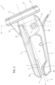
- the support system 1 is advantageously shaped like a peg and therefore comprises a first jaw 2' and a second jaw 2'', each extending along a longitudinal axis A of the support system and connected to each other as described below.
- each jaw 2', 2" comprises a first end portion 2a', 2a" and a second end portion 2b', 2b" facing each other along a vertical axis B perpendicular to the longitudinal axis A.
- the first end portions 2a', 2a" are connected to each other as described below so as to allow the second end portions 2b', 2b" to move away from each other, in particular to rotate around a common rotation axis B, perpendicular to the longitudinal and transversal axes A, B, between a first position, in which they are at a minimum distance from each other, potentially in contact, and a second position of maximum distance from each other.
- the support system comprises engagement portions 3 carried by each of the second end portions 2b', 2b" and configured to cooperate in contact with the aforementioned vehicular portion 2.
- these engagement portions 3 comprise a plurality of teeth 4 carried by projections 5 extending starting from the respective second end portions 2b', 2b".
- the upper jaw 2' has a substantially constant shape along the longitudinal axis A, whereas the lower jaw 2" has a greater thickness in the second end 2b", thus defining an inverted "L" shape.
- the teeth 4 made on the second end portion 2b" of the lower jaw 2" are made on a projection running along this thicker portion and are less along the extension of the longitudinal axis A than the teeth 4 made on the second end portion 2b' of the upper jaw 2'.
- a space 6 is defined between the upper jaw 2' and the lower jaw 2", the space 6 being vertically delimited by the intermediate portions of the same jaws 2', 2" and longitudinally delimited by the first end portions 2a', 2a" and the second end portions 2b', 2b".
- the space 6 is configured to house, on the inside, part of the vehicular portion 2 on which the jaws 2', 2" exert a compressive force suitable to keep the support system 1 fixed thereto.
- the support system 1 further comprises adjustment means 7 housed in the space 6 and configured to vary the free housing space thereof.
- the adjustment means 7 may comprise a protuberance extending from one of the jaws 2', 2" in the space 6, for example as shown by the lower jaw 2".
- the two jaws 2', 2" are connected to each other at the first ends 2a', 2a" via a movable connection, such as a hinge 8.
- a hinge 8 is provided between the first end 2a' and the second end 2a" and also includes elastic means, not shown, configured to exert a force opposing the transition of the jaws 2', 2" from the first position to the second position as mentioned above.
- the first end 2a' of the upper jaw 2' is sized so as to house, on the inside, along the direction of the rotation axis C, the first end 2a' ' of the lower jaw 2".
- the first end 2a' of the upper jaw 2' is U-shaped and contains, within the arms of this "U", the first end 2a" of the lower jaw 2".
- the support system comprises release means 9 configured to bypass the hinge 8 and allow the jaws 2', 2" to open when controlled by the user in order to facilitate the coupling to the vehicular portion 2.
- release means 9 may comprise, as shown, a lever 11 suitable to control, for example, a bayonet fitting designed to take a first operating configuration, where it keeps the operation of the hinge 8 free, and a second operating configuration, where it opens the jaws 8', 8" by-passing the hinge 8.
- a lever 11 suitable to control for example, a bayonet fitting designed to take a first operating configuration, where it keeps the operation of the hinge 8 free, and a second operating configuration, where it opens the jaws 8', 8" by-passing the hinge 8.
- this lever 11 is movably housed through the lower jaw 2" close to the hinge 8.
- the support system 1 further comprises a coupling portion 12 carried by one of the upper jaw 2' and lower jaw 2" and configured to allow the above-mentioned device D to be fixed. in the embodiment described, the coupling portion 12 is carried by the upper jaw 2'.
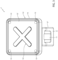
- the coupling portion 12 comprises a support wall 12' fixed to the upper jaw 2'.
- the wall 12' has a substantially quadrangular shape, preferably square, extending along the direction of the vertical B and rotation C axes, i.e., perpendicular to the longitudinal axis A.
- the coupling portion 12 may also include a reinforcing flange 12" extending perpendicular to the support wall 12' relative to the upper jaw 2' and configured to increase the strength of their connection.
- the wall 12' and/or the flange 12" can be made in one piece with the upper jaw 2'.
- the coupling portion 12 also defines a plurality of fixing points 13, such as through holes, made on part of the surface of the wall 12'. In the embodiment shown, there are as many holes as the vertices of the shape of the wall 12'.
- the fixing points 13 allow the fixing of the device D to the support system 1.
- the support system 1 may also comprise magnetic elements 14 carried by the wall 12' and advantageously integrated therewith, which are configured to exert a force for holding the device D on the wall 12.
- the support system 1 may comprise damping elements 15 carried by the wall 12' and interposed in contact with the device D when cooperating in contact therewith in order to reduce the transmission of vehicular vibrations.
- damping elements 15 may comprise a sheath of compressible material placed on at least part of the surface of the wall 12', for example on at least part of its outer perimeter or, as in the embodiment shown, on the inner perimeter thereof.
- the support system 1 can be made of any material, advantageously of a plastic or polymeric type.
- the user may move the jaws 2', 2" to their maximum distance so that a vehicular portion 2 can be housed within the space 6, which pivots between them (or between them and the adjustment means 7).
- the device D can be fixed to the coupling portion 12 ( Figure 4A ).
- the proposed support system makes it possible to provide a firm support for a device D, without drilling holes in the vehicle dashboard. Furthermore, it is possible to arrange this device D in different positions.
- the hinge means 8 equipped with elastic means and the shape of the jaws 2', 2" make it possible to fix the device D firmly to the vehicular portion 2, even to very thick vehicular portions 2 other than the air vents.
- the presence of the magnetic elements 14 and the damping elements 15 also makes it possible to fix the device D firmly, preventing sudden detachments, if the fixing points 13 are not used, or the transmission of vibrations.
- the presence of several fixing points 13 makes it possible to fix different devices D to the vehicular portion 2 without necessarily having to drill holes therein.
- the shape of the jaws 2', 2" or how they couple to each other may vary.
- the engagement portions 3 or the release means 9 can be made in an equivalent way.
- adjustment means, the magnetic elements 14 and the damping elements 15 can be absent or made in a different shape, as can the number and type of fixing points.
Landscapes
- Engineering & Computer Science (AREA)
- Mechanical Engineering (AREA)
- Connection Of Plates (AREA)
Abstract
Description
- This patent application claims priority from
Italian patent application no. 102023000011958 filed on June 12, 2023 - The present invention relates to a vehicular support.
- The present invention finds its preferred, though not exclusive, application in a cab of a vehicle, such as a commercial vehicle. This application will be referred to hereinafter by way of example.
- Commercial vehicles, such as Light Commercial Vehicles (LCV), or heavy-duty vehicles, such as lorries or trucks, are equipped with a cab defining a driving position.
- There is an increasing need to provide cabs which are as comfortable and ergonomic as possible. One element affecting the comfort and ergonomics of cabs is the positioning of control displays controlling the vehicle or parts thereof.
- In the state of the art, such displays are fixed to fixed positions on the dashboard according to the specific type of vehicle and according to the driver's needs.
- Therefore, a substantially artisan operation is needed to modify the dashboard in order to make the holes to fix the control display.
- It is clear that this manual operation is time-consuming, difficult and prone to error. In addition, if the position of the display were to change over time, the dashboard would have to be reworked and the previous holes would have to be repaired or they would be visible.
- Furthermore, once fixed, the display cannot be moved, consequently its position may not be advantageous depending on the height of the driver, which can vary considerably.
- The object of the present invention is to meet the above needs in an optimized and cost-effective manner.
- Said object is achieved by means of a support system and a vehicle as claimed in the appended claims.
- For a better understanding of the present invention, a preferred embodiment is described below by way of nonlimiting example and with reference to the accompanying drawings, wherein:
-
Figure 1 is a perspective view of a support system according to the invention; -
Figure 2 is a side view of the support system inFigure 1 ; -
Figure 3 is a front view of the support system inFigure 1 ; -
Figures 4A and 4B illustrate two different positions of the support system according toFigure 1 on a vehicular portion. - In the figures shown herein, 1 indicates a support system according to the invention, which can be used to fix a device D to a vehicular portion 2 (
Figures 4A-4B ), such as, for example, a portion of a vehicular dashboard. - The support system 1 is advantageously shaped like a peg and therefore comprises a first jaw 2' and a second jaw 2'', each extending along a longitudinal axis A of the support system and connected to each other as described below.
- In particular, each
jaw 2', 2" comprises afirst end portion 2a', 2a" and asecond end portion 2b', 2b" facing each other along a vertical axis B perpendicular to the longitudinal axis A. - The
first end portions 2a', 2a" are connected to each other as described below so as to allow thesecond end portions 2b', 2b" to move away from each other, in particular to rotate around a common rotation axis B, perpendicular to the longitudinal and transversal axes A, B, between a first position, in which they are at a minimum distance from each other, potentially in contact, and a second position of maximum distance from each other. - In particular, the support system comprises
engagement portions 3 carried by each of thesecond end portions 2b', 2b" and configured to cooperate in contact with the aforementionedvehicular portion 2. Advantageously, theseengagement portions 3 comprise a plurality ofteeth 4 carried byprojections 5 extending starting from the respectivesecond end portions 2b', 2b". - In further detail, the upper jaw 2' has a substantially constant shape along the longitudinal axis A, whereas the
lower jaw 2" has a greater thickness in thesecond end 2b", thus defining an inverted "L" shape. - Preferably, the
teeth 4 made on thesecond end portion 2b" of thelower jaw 2" are made on a projection running along this thicker portion and are less along the extension of the longitudinal axis A than theteeth 4 made on thesecond end portion 2b' of the upper jaw 2'. - A
space 6 is defined between the upper jaw 2' and thelower jaw 2", thespace 6 being vertically delimited by the intermediate portions of thesame jaws 2', 2" and longitudinally delimited by thefirst end portions 2a', 2a" and thesecond end portions 2b', 2b". - The
space 6 is configured to house, on the inside, part of thevehicular portion 2 on which thejaws 2', 2" exert a compressive force suitable to keep the support system 1 fixed thereto. - In particular, the support system 1 further comprises adjustment means 7 housed in the
space 6 and configured to vary the free housing space thereof. In detail, the adjustment means 7 may comprise a protuberance extending from one of thejaws 2', 2" in thespace 6, for example as shown by thelower jaw 2". - As mentioned above, the two
jaws 2', 2" are connected to each other at thefirst ends 2a', 2a" via a movable connection, such as ahinge 8. Advantageously, thehinge 8 is provided between thefirst end 2a' and thesecond end 2a" and also includes elastic means, not shown, configured to exert a force opposing the transition of thejaws 2', 2" from the first position to the second position as mentioned above. - In detail, the
first end 2a' of the upper jaw 2' is sized so as to house, on the inside, along the direction of the rotation axis C, thefirst end 2a' ' of thelower jaw 2". For this purpose, in the embodiment described, thefirst end 2a' of the upper jaw 2' is U-shaped and contains, within the arms of this "U", thefirst end 2a" of thelower jaw 2". - Advantageously, the support system comprises release means 9 configured to bypass the
hinge 8 and allow thejaws 2', 2" to open when controlled by the user in order to facilitate the coupling to thevehicular portion 2. - These release means 9 may comprise, as shown, a
lever 11 suitable to control, for example, a bayonet fitting designed to take a first operating configuration, where it keeps the operation of thehinge 8 free, and a second operating configuration, where it opens thejaws 8', 8" by-passing thehinge 8. - Advantageously, in the embodiment described, this
lever 11 is movably housed through thelower jaw 2" close to thehinge 8. - The support system 1 further comprises a
coupling portion 12 carried by one of the upper jaw 2' andlower jaw 2" and configured to allow the above-mentioned device D to be fixed. in the embodiment described, thecoupling portion 12 is carried by the upper jaw 2'. - In particular, the
coupling portion 12 comprises a support wall 12' fixed to the upper jaw 2'. In the embodiment shown, the wall 12' has a substantially quadrangular shape, preferably square, extending along the direction of the vertical B and rotation C axes, i.e., perpendicular to the longitudinal axis A. - The
coupling portion 12 may also include a reinforcingflange 12" extending perpendicular to the support wall 12' relative to the upper jaw 2' and configured to increase the strength of their connection. - Advantageously, the wall 12' and/or the
flange 12" can be made in one piece with the upper jaw 2'. - The
coupling portion 12 also defines a plurality offixing points 13, such as through holes, made on part of the surface of the wall 12'. In the embodiment shown, there are as many holes as the vertices of the shape of the wall 12'. Thefixing points 13 allow the fixing of the device D to the support system 1. - In addition, the support system 1 may also comprise
magnetic elements 14 carried by the wall 12' and advantageously integrated therewith, which are configured to exert a force for holding the device D on thewall 12. - Furthermore, the support system 1 may comprise
damping elements 15 carried by the wall 12' and interposed in contact with the device D when cooperating in contact therewith in order to reduce the transmission of vehicular vibrations.Such damping elements 15 may comprise a sheath of compressible material placed on at least part of the surface of the wall 12', for example on at least part of its outer perimeter or, as in the embodiment shown, on the inner perimeter thereof. - The support system 1 can be made of any material, advantageously of a plastic or polymeric type.
- The operation of the above-described embodiment of the support system according to the invention is as follows.
- By acting on the release means 9, the user may move the
jaws 2', 2" to their maximum distance so that avehicular portion 2 can be housed within thespace 6, which pivots between them (or between them and the adjustment means 7). Once the desired position has been reached, the device D can be fixed to the coupling portion 12 (Figure 4A ). - If the device D is changed or there is a desire to change its position (
Figure 4B ), it is sufficient to act on the release means 9 again in order to reposition thejaws 2, 2' differently on thevehicular portion 2. - The advantages of a support system according to the invention are clear from the foregoing.
- The proposed support system makes it possible to provide a firm support for a device D, without drilling holes in the vehicle dashboard. Furthermore, it is possible to arrange this device D in different positions.
- The hinge means 8 equipped with elastic means and the shape of the
jaws 2', 2" make it possible to fix the device D firmly to thevehicular portion 2, even to very thickvehicular portions 2 other than the air vents. - The presence of the
magnetic elements 14 and the dampingelements 15 also makes it possible to fix the device D firmly, preventing sudden detachments, if the fixing points 13 are not used, or the transmission of vibrations. - Also, the presence of several fixing points 13 makes it possible to fix different devices D to the
vehicular portion 2 without necessarily having to drill holes therein. - Lastly, it is clear that modifications and variations may be made to the support system according to the present invention, without however departing from the scope of protection defined by the claims.
- For example, the shape of the
jaws 2', 2" or how they couple to each other may vary. Similarly, theengagement portions 3 or the release means 9 can be made in an equivalent way. - In addition, the adjustment means, the
magnetic elements 14 and the dampingelements 15 can be absent or made in a different shape, as can the number and type of fixing points.
Claims (14)
- A support system (1) for fixing a device (D) to a vehicular portion (2), said support system (1) comprising a first jaw (2') and a second jaw (2'') each provided with a first end (2a', 2a") and a second end (2b', 2b'') opposite along a longitudinal axis (A) of said support system (1), said first and second jaws (2', 2'') being connected via a movable connection made between said first ends (2a', 2a") so as to allow the movement of said second ends (2b', 2b'') between a first position of minimum distance from each other along a vertical axis (B) perpendicular to said longitudinal axis (A) and a second position of maximum distance from each other along said vertical axis (B), said second ends (2b', 2b") being provided with engagement portions (3) adapted to cooperate in contact with said vehicular portion (2), said support system (1) comprising a coupling portion (12) carried by one of said first and second jaws (2', 2'') and configured to allow said device (D) to be rigidly connected thereto, wherein said coupling portion (12) comprises a wall (12') defining a plurality of fixing points (13) to allow the fixing of said device (D),
said system further comprising damping elements (15) carried by said wall (12') and configured to cooperate interposed between said wall (12') and said device (D) when fixed to said wall (12') in order to dampen vehicular vibrations. - The system according to Claim 1, wherein said fixing points (13) comprise holes passing through said wall (12').
- The system according to claim 1 or 2, further comprising magnetic elements (14) carried by said wall (12').
- The system according to one of claims 1 to 3, comprising a flange (12'') connecting said wall (12') to said one of said first and second jaws (2', 2").
- The support system according to one of the preceding claims, comprising release means (9) carried by one of said first and second jaws (2', 2'') and configured to carry said first and second jaws (2', 2'') in said second position.
- The support system according to one of the preceding claims, wherein said jaws (2', 2' ') are each made in one piece.
- The support system according to one of the preceding claims, wherein said jaws (2', 2'') are each made of polymeric/plastic material.
- The system according to any one of the preceding claims, wherein said movable connection comprises a hinge (8) able to allow rotation around an axis (C) perpendicular to said longitudinal and vertical axes (A, B).
- The system according to one of the preceding claims, wherein said engagement portions (3) comprise a plurality of teeth (4) extending from the respective first and second jaws (2', 2'').
- The system according to claim 9, wherein said plurality of teeth (4) extend starting from a projection extending starting from the respective first and second jaws (2', 2").
- The system according to one of the preceding claims, wherein one of said first ends (2a', 2a") is housed inside the other of said first ends (2a', 2a").
- The system according to one of the preceding claims, wherein a space (6) is delimited between said first and second jaws (2', 2'') suitable for housing, in use, said vehicular portion (2), said support system (1) comprising adjustment means (7) housed in said space (6) and carried by one of said first and second jaws (2', 2'') and configured to cooperate in contact with said vehicular portion (2).
- The system according to Claim 12, wherein said adjustment means (7) comprise a protuberance extending from said second jaw (2'') towards said first jaw (2').
- The system according to one of the preceding claims, wherein said first jaw (2') has a substantially constant thickness between said first end (2a') and said second end (2b'), said second jaw (2") having a greater thickness in said second end (2b') than in said first end (2a') .
Applications Claiming Priority (1)
| Application Number | Priority Date | Filing Date | Title |
|---|---|---|---|
| IT102023000011958A IT202300011958A1 (en) | 2023-06-12 | 2023-06-12 | IMPROVED VEHICLE SUPPORT SYSTEM |
Publications (2)
| Publication Number | Publication Date |
|---|---|
| EP4477473A1 true EP4477473A1 (en) | 2024-12-18 |
| EP4477473B1 EP4477473B1 (en) | 2026-02-25 |
Family
ID=87889620
Family Applications (1)
| Application Number | Title | Priority Date | Filing Date |
|---|---|---|---|
| EP24179895.8A Active EP4477473B1 (en) | 2023-06-12 | 2024-06-04 | Improved vehicular support system |
Country Status (2)
| Country | Link |
|---|---|
| EP (1) | EP4477473B1 (en) |
| IT (1) | IT202300011958A1 (en) |
Citations (7)
| Publication number | Priority date | Publication date | Assignee | Title |
|---|---|---|---|---|
| CA2505344A1 (en) * | 2005-04-28 | 2006-10-28 | Zhi Xiong Huo | Portable and car-borne dual-purpose lcd screen holding device |
| US20140103087A1 (en) * | 2012-10-12 | 2014-04-17 | Eagle Fan | Fixture apparatus for automotive air-conditioning outlet |
| US20160288731A1 (en) * | 2013-12-12 | 2016-10-06 | Joonho Oh | Mounting device for vehicle |
| DE202017003554U1 (en) * | 2017-07-06 | 2017-10-19 | Eagle Fan | CD slot compatible connection platform |
| CN207466532U (en) * | 2017-08-23 | 2018-06-08 | 王慧超 | A kind of Automobile handset stent |
| CN109131136A (en) * | 2018-10-11 | 2019-01-04 | 东莞市北扬工业设计有限公司 | Clamp of automobile air outlet |
| KR20220081952A (en) * | 2020-12-09 | 2022-06-16 | 주식회사아리움 | Potable Holder |
Family Cites Families (1)
| Publication number | Priority date | Publication date | Assignee | Title |
|---|---|---|---|---|
| NL2002690C2 (en) * | 2009-03-31 | 2010-10-04 | Amaiak Khatchatrian | UNIVERSAL HOLDER FOR A NAVIGATION SYSTEM. |
-
2023
- 2023-06-12 IT IT102023000011958A patent/IT202300011958A1/en unknown
-
2024
- 2024-06-04 EP EP24179895.8A patent/EP4477473B1/en active Active
Patent Citations (7)
| Publication number | Priority date | Publication date | Assignee | Title |
|---|---|---|---|---|
| CA2505344A1 (en) * | 2005-04-28 | 2006-10-28 | Zhi Xiong Huo | Portable and car-borne dual-purpose lcd screen holding device |
| US20140103087A1 (en) * | 2012-10-12 | 2014-04-17 | Eagle Fan | Fixture apparatus for automotive air-conditioning outlet |
| US20160288731A1 (en) * | 2013-12-12 | 2016-10-06 | Joonho Oh | Mounting device for vehicle |
| DE202017003554U1 (en) * | 2017-07-06 | 2017-10-19 | Eagle Fan | CD slot compatible connection platform |
| CN207466532U (en) * | 2017-08-23 | 2018-06-08 | 王慧超 | A kind of Automobile handset stent |
| CN109131136A (en) * | 2018-10-11 | 2019-01-04 | 东莞市北扬工业设计有限公司 | Clamp of automobile air outlet |
| KR20220081952A (en) * | 2020-12-09 | 2022-06-16 | 주식회사아리움 | Potable Holder |
Also Published As
| Publication number | Publication date |
|---|---|
| EP4477473B1 (en) | 2026-02-25 |
| IT202300011958A1 (en) | 2024-12-12 |
Similar Documents
| Publication | Publication Date | Title |
|---|---|---|
| US4903541A (en) | Anchoring and adjusting assembly for a control cable | |
| US6270158B1 (en) | Lumbar support locking apparatus for a car seat | |
| US4690432A (en) | Automobile instrument cluster tiltable with a steering column | |
| KR101469465B1 (en) | Adjustment device for motor vehicle seats and an adjustable motor vehicle seat | |
| CN112141009A (en) | Fastening device for adjustable attachments | |
| US4508385A (en) | Seat track assembly | |
| JPH0242276A (en) | Shifting device for car transmission | |
| US6923490B2 (en) | Slidable sun visor assembly | |
| EP4477473B1 (en) | Improved vehicular support system | |
| EP1982865B1 (en) | Height adjustment device for heavy equipment console box having weight balancing | |
| JPH05505995A (en) | automotive sun visor | |
| EP0894671B1 (en) | Vehicle mirror apparatus | |
| EP3012490A1 (en) | Shift device | |
| EP1174301B1 (en) | A transmission control apparatus for an automobile | |
| US6409246B1 (en) | Snap-in hinged visor extender | |
| EP4238819B1 (en) | Improved armrest arrangement for a work vehicle | |
| EP3950473B1 (en) | Windshield device for saddle-ride type vehicle | |
| EP0908347B1 (en) | Arrangement for attaching gearshift assembly and method of assembling the same | |
| EP0001478A1 (en) | Gear ratio changing mechanism | |
| US5737972A (en) | Rearview mirror for motor vehicles | |
| EP0598882A1 (en) | Device for fixing sun visors of motor vehicles | |
| KR101925458B1 (en) | Seat supporting device for heavy vehicle | |
| JP2009101759A (en) | Mounting structure for vehicle height sensor | |
| DE102019126755B4 (en) | Holding device for storing and positioning a portable mobile device, system and motor vehicle | |
| KR20180122503A (en) | Seat supporting device for heavy vehicle |
Legal Events
| Date | Code | Title | Description |
|---|---|---|---|
| PUAI | Public reference made under article 153(3) epc to a published international application that has entered the european phase |
Free format text: ORIGINAL CODE: 0009012 |
|
| STAA | Information on the status of an ep patent application or granted ep patent |
Free format text: STATUS: THE APPLICATION HAS BEEN PUBLISHED |
|
| AK | Designated contracting states |
Kind code of ref document: A1 Designated state(s): AL AT BE BG CH CY CZ DE DK EE ES FI FR GB GR HR HU IE IS IT LI LT LU LV MC ME MK MT NL NO PL PT RO RS SE SI SK SM TR |
|
| STAA | Information on the status of an ep patent application or granted ep patent |
Free format text: STATUS: REQUEST FOR EXAMINATION WAS MADE |
|
| 17P | Request for examination filed |
Effective date: 20250521 |
|
| GRAP | Despatch of communication of intention to grant a patent |
Free format text: ORIGINAL CODE: EPIDOSNIGR1 |
|
| STAA | Information on the status of an ep patent application or granted ep patent |
Free format text: STATUS: GRANT OF PATENT IS INTENDED |
|
| INTG | Intention to grant announced |
Effective date: 20250925 |
|
| GRAS | Grant fee paid |
Free format text: ORIGINAL CODE: EPIDOSNIGR3 |
|
| GRAA | (expected) grant |
Free format text: ORIGINAL CODE: 0009210 |
|
| STAA | Information on the status of an ep patent application or granted ep patent |
Free format text: STATUS: THE PATENT HAS BEEN GRANTED |
|
| P01 | Opt-out of the competence of the unified patent court (upc) registered |
Free format text: CASE NUMBER: UPC_APP_0019120_4477473/2025 Effective date: 20251222 |
|
| AK | Designated contracting states |
Kind code of ref document: B1 Designated state(s): AL AT BE BG CH CY CZ DE DK EE ES FI FR GB GR HR HU IE IS IT LI LT LU LV MC ME MK MT NL NO PL PT RO RS SE SI SK SM TR |
|
| REG | Reference to a national code |
Ref country code: CH Ref legal event code: F10 Free format text: ST27 STATUS EVENT CODE: U-0-0-F10-F00 (AS PROVIDED BY THE NATIONAL OFFICE) Effective date: 20260225 Ref country code: GB Ref legal event code: FG4D |
|
| REG | Reference to a national code |
Ref country code: DE Ref legal event code: R096 Ref document number: 602024002767 Country of ref document: DE |
|
| REG | Reference to a national code |
Ref country code: IE Ref legal event code: FG4D |