EP4477441A1 - Vehicle with side ducts for the confinement of a central hot flow - Google Patents
Vehicle with side ducts for the confinement of a central hot flow Download PDFInfo
- Publication number
- EP4477441A1 EP4477441A1 EP24181307.0A EP24181307A EP4477441A1 EP 4477441 A1 EP4477441 A1 EP 4477441A1 EP 24181307 A EP24181307 A EP 24181307A EP 4477441 A1 EP4477441 A1 EP 4477441A1
- Authority
- EP
- European Patent Office
- Prior art keywords
- vehicle
- compartment
- vehicle according
- air
- mouths
- Prior art date
- Legal status (The legal status is an assumption and is not a legal conclusion. Google has not performed a legal analysis and makes no representation as to the accuracy of the status listed.)
- Granted
Links
Images


Classifications
-
- B—PERFORMING OPERATIONS; TRANSPORTING
- B60—VEHICLES IN GENERAL
- B60K—ARRANGEMENT OR MOUNTING OF PROPULSION UNITS OR OF TRANSMISSIONS IN VEHICLES; ARRANGEMENT OR MOUNTING OF PLURAL DIVERSE PRIME-MOVERS IN VEHICLES; AUXILIARY DRIVES FOR VEHICLES; INSTRUMENTATION OR DASHBOARDS FOR VEHICLES; ARRANGEMENTS IN CONNECTION WITH COOLING, AIR INTAKE, GAS EXHAUST OR FUEL SUPPLY OF PROPULSION UNITS IN VEHICLES
- B60K11/00—Arrangement in connection with cooling of propulsion units
- B60K11/02—Arrangement in connection with cooling of propulsion units with liquid cooling
- B60K11/04—Arrangement or mounting of radiators, radiator shutters, or radiator blinds
-
- B—PERFORMING OPERATIONS; TRANSPORTING
- B60—VEHICLES IN GENERAL
- B60H—ARRANGEMENTS OF HEATING, COOLING, VENTILATING OR OTHER AIR-TREATING DEVICES SPECIALLY ADAPTED FOR PASSENGER OR GOODS SPACES OF VEHICLES
- B60H1/00—Heating, cooling or ventilating devices
- B60H1/24—Ventilating devices where the heating or cooling is irrelevant
- B60H1/26—Ventilating openings in vehicle exterior; Ducts for conveying ventilating air
- B60H1/30—Air scoops
-
- B—PERFORMING OPERATIONS; TRANSPORTING
- B60—VEHICLES IN GENERAL
- B60H—ARRANGEMENTS OF HEATING, COOLING, VENTILATING OR OTHER AIR-TREATING DEVICES SPECIALLY ADAPTED FOR PASSENGER OR GOODS SPACES OF VEHICLES
- B60H1/00—Heating, cooling or ventilating devices
- B60H1/24—Ventilating devices where the heating or cooling is irrelevant
- B60H1/26—Ventilating openings in vehicle exterior; Ducts for conveying ventilating air
- B60H1/28—Ventilating openings in vehicle exterior; Ducts for conveying ventilating air the openings being situated directly in front of vehicle front window
-
- B—PERFORMING OPERATIONS; TRANSPORTING
- B60—VEHICLES IN GENERAL
- B60K—ARRANGEMENT OR MOUNTING OF PROPULSION UNITS OR OF TRANSMISSIONS IN VEHICLES; ARRANGEMENT OR MOUNTING OF PLURAL DIVERSE PRIME-MOVERS IN VEHICLES; AUXILIARY DRIVES FOR VEHICLES; INSTRUMENTATION OR DASHBOARDS FOR VEHICLES; ARRANGEMENTS IN CONNECTION WITH COOLING, AIR INTAKE, GAS EXHAUST OR FUEL SUPPLY OF PROPULSION UNITS IN VEHICLES
- B60K13/00—Arrangement in connection with combustion air intake or gas exhaust of propulsion units
- B60K13/02—Arrangement in connection with combustion air intake or gas exhaust of propulsion units concerning intake
-
- B—PERFORMING OPERATIONS; TRANSPORTING
- B60—VEHICLES IN GENERAL
- B60K—ARRANGEMENT OR MOUNTING OF PROPULSION UNITS OR OF TRANSMISSIONS IN VEHICLES; ARRANGEMENT OR MOUNTING OF PLURAL DIVERSE PRIME-MOVERS IN VEHICLES; AUXILIARY DRIVES FOR VEHICLES; INSTRUMENTATION OR DASHBOARDS FOR VEHICLES; ARRANGEMENTS IN CONNECTION WITH COOLING, AIR INTAKE, GAS EXHAUST OR FUEL SUPPLY OF PROPULSION UNITS IN VEHICLES
- B60K11/00—Arrangement in connection with cooling of propulsion units
- B60K11/02—Arrangement in connection with cooling of propulsion units with liquid cooling
-
- B—PERFORMING OPERATIONS; TRANSPORTING
- B60—VEHICLES IN GENERAL
- B60K—ARRANGEMENT OR MOUNTING OF PROPULSION UNITS OR OF TRANSMISSIONS IN VEHICLES; ARRANGEMENT OR MOUNTING OF PLURAL DIVERSE PRIME-MOVERS IN VEHICLES; AUXILIARY DRIVES FOR VEHICLES; INSTRUMENTATION OR DASHBOARDS FOR VEHICLES; ARRANGEMENTS IN CONNECTION WITH COOLING, AIR INTAKE, GAS EXHAUST OR FUEL SUPPLY OF PROPULSION UNITS IN VEHICLES
- B60K11/00—Arrangement in connection with cooling of propulsion units
- B60K11/08—Air inlets for cooling; Shutters or blinds therefor
-
- B—PERFORMING OPERATIONS; TRANSPORTING
- B60—VEHICLES IN GENERAL
- B60K—ARRANGEMENT OR MOUNTING OF PROPULSION UNITS OR OF TRANSMISSIONS IN VEHICLES; ARRANGEMENT OR MOUNTING OF PLURAL DIVERSE PRIME-MOVERS IN VEHICLES; AUXILIARY DRIVES FOR VEHICLES; INSTRUMENTATION OR DASHBOARDS FOR VEHICLES; ARRANGEMENTS IN CONNECTION WITH COOLING, AIR INTAKE, GAS EXHAUST OR FUEL SUPPLY OF PROPULSION UNITS IN VEHICLES
- B60K13/00—Arrangement in connection with combustion air intake or gas exhaust of propulsion units
- B60K13/06—Arrangement in connection with combustion air intake or gas exhaust of propulsion units using structural parts of the vehicle as ducts, e.g. frame parts
Definitions
- the invention relates to a vehicle.
- the invention particularly advantageously applies to a hybrid vehicle provided with an internal combustion engine and with an electric motor, to which explicit reference will be made in the description below without because of this lacking generality.
- a vehicle which comprises a support frame defining part of a lower floor of the vehicle; a passenger compartment mounted on the support frame and projecting upwards from the lower floor; an outer body; a front compartment obtained within the outer body and delimited by a front bumper and by a front hood; and a rear compartment obtained within the outer body.
- the vehicle is further provided with a main internal combustion engine accommodated in the rear compartment, with a compressor to supply compressed air to the main engine, with a heat exchanger to cool the air supplied by the compressor to the main engine and with a pair of intake mouths to supply air coming from the outside to the heat exchanger.
- the vehicle further comprises at least one pair of additional intake mouths to connect the outside and the passenger compartment to one another; an air heating/conditioning system to heat/condition the air supplied to the passenger compartment through the additional intake mouths; and an auxiliary electric motor accommodated in the front compartment and associated with a front radiator mounted along a supply duct communicating with the outside.
- the vehicle further comprises an aerodynamic bottom, which is fixed to the support frame, defines part of the lower floor and comprises, in turn, a front bottom, which is mounted in the area of the front compartment, a rear bottom, which is mounted in the area of the rear compartment, and a central bottom, which is mounted in the area of the passenger compartment.
- an aerodynamic bottom which is fixed to the support frame, defines part of the lower floor and comprises, in turn, a front bottom, which is mounted in the area of the front compartment, a rear bottom, which is mounted in the area of the rear compartment, and a central bottom, which is mounted in the area of the passenger compartment.
- the front bottom Since the vehicle must be subject to a relatively large vertical load, the front bottom must be closed and the supply duct must extend through the front hood starting from the front bumper.
- the object of the invention is to provide a vehicle that is not affected by the aforementioned drawbacks and can be manufactured in a simple and economic fashion.
- number 1 indicates, as a whole, a vehicle, specifically a hybrid vehicle, comprising a support frame 2 defining at least part of a lower floor 3 of the vehicle 1, a passenger compartment 4 mounted on the frame 2 and projecting upwards from the floor 3 and an outer body 5.
- the vehicle 1 further comprises a front compartment 6 obtained within the body 5 and a rear compartment 7 obtained within the body 5.
- the front compartment 6 is delimited by a front bumper 8 and by a front hood 9 and accommodates, on the inside, a first motor 10, specifically an electric motor, and a front radiator 11 to cool the motor 10.
- the radiator 11 is arranged along a central duct 12, which extends inside the compartment 6 between the bumper 8 and the hood 9 and opens outwards both through the bumper 8 and through the hood 9.
- the compartment 6 also houses, on the inside, two side ducts 13, which are arranged on opposite sides of the duct 12, extend between the bumper 8 and the hood 9, are S-shaped and open outwards both through the bumper 8 and through the hood 9.
- the hood 9 has, in this case, two openings 14, each provided with a dividing partition 15 defining two outlet mouths 16, 17, the mouth 16 being an inner mouth communicating with the duct 12 and the mouth 17 being an outer mouth communicating with a duct 13.
- the air flow F flowing into the compartment 6 during the normal running of the vehicle 1 is divided into a central air flow F1, which is supplied along the duct 12, through the radiator 11 and to the mouths 16, and into two side air flows F2, which are supplied along the relative ducts 13 and to the relative mouths 17.
- the central air flow F1 When flowing out of the hood 9, the central air flow F1 is laterally delimited by the two side air flows F2, which do not flow through the radiator 11 and, therefore, have a lower temperature than a temperature of the central air flow F1.
- the rear compartment 7 houses, on the inside, a second engine 18, specifically an internal combustion engine, a known and not shown turbocharger to supply compressed air to the engine 18 and at least one heat exchanger (not shown), commonly known as “intercooler”, to cool the compressed air supplied by the turbocharger (not shown) to the engine 18.
- a second engine 18 specifically an internal combustion engine
- a known and not shown turbocharger to supply compressed air to the engine 18
- at least one heat exchanger commonly known as "intercooler”
- the vehicle 1 is further provided with a pair of intake mouths 19, which are obtained between the passenger compartment 4 and the rear compartment 7 and open outwards through the body 5 in the area of the side flanks of the vehicle 1 to supply air to the heat exchanger (not shown).
- the vehicle 1 further comprises a known air heating/conditioning system, which is not shown herein, to supply hot/conditioned air into the passenger compartment 4, a first pair of intake mouths 20 obtained under the hood 9 to supply air into the passenger compartment 4 through the air heating/conditioning system and a second pair of intake mouths 21 obtained along a lower edge of a front windshield 22 to supply air into the passenger compartment 4 through the air heating/conditioning system.
- a known air heating/conditioning system which is not shown herein, to supply hot/conditioned air into the passenger compartment 4, a first pair of intake mouths 20 obtained under the hood 9 to supply air into the passenger compartment 4 through the air heating/conditioning system and a second pair of intake mouths 21 obtained along a lower edge of a front windshield 22 to supply air into the passenger compartment 4 through the air heating/conditioning system.
- the mouths 19, 20, 21 of each pair of mouths 19, 20, 21 are substantially symmetrical relative to a longitudinal symmetry plane of the vehicle and are arranged so that the distance between the mouths 17, measured crosswise to a forward moving direction 23 of the vehicle 1, is smaller than the distance between the mouths 19, the distance between the mouths 20 and the distance between the mouths 21, which are also measured crosswise to the direction 23.
- the air flows F2 namely the air flows at a lower temperature
- the air flows F1 namely the air flow at a higher temperature
- the vehicle 1 finally comprises an aerodynamic bottom 24, which is fixed to the frame 2, defines part of the floor 3 and comprises, in turn, a front bottom 25, which is mounted in the area of the front compartment 6, a rear bottom 26, which is mounted in the area of the rear compartment 7, and a central bottom 27, which is mounted in the area of the passenger compartment 4.
- At least the front bottom 25 is closed so as to exert a relatively high vertical load upon the vehicle 1.
Landscapes
- Engineering & Computer Science (AREA)
- Mechanical Engineering (AREA)
- Chemical & Material Sciences (AREA)
- Combustion & Propulsion (AREA)
- Transportation (AREA)
- Physics & Mathematics (AREA)
- Thermal Sciences (AREA)
- Cooling, Air Intake And Gas Exhaust, And Fuel Tank Arrangements In Propulsion Units (AREA)
Abstract
Description
- This patent application claims priority from
Italian patent application no. 102023000012393 filed on June 16, 2023 - The invention relates to a vehicle.
- The invention particularly advantageously applies to a hybrid vehicle provided with an internal combustion engine and with an electric motor, to which explicit reference will be made in the description below without because of this lacking generality.
- In the field of hybrid vehicles, a vehicle is known, which comprises a support frame defining part of a lower floor of the vehicle; a passenger compartment mounted on the support frame and projecting upwards from the lower floor; an outer body; a front compartment obtained within the outer body and delimited by a front bumper and by a front hood; and a rear compartment obtained within the outer body.
- The vehicle is further provided with a main internal combustion engine accommodated in the rear compartment, with a compressor to supply compressed air to the main engine, with a heat exchanger to cool the air supplied by the compressor to the main engine and with a pair of intake mouths to supply air coming from the outside to the heat exchanger.
- The vehicle further comprises at least one pair of additional intake mouths to connect the outside and the passenger compartment to one another; an air heating/conditioning system to heat/condition the air supplied to the passenger compartment through the additional intake mouths; and an auxiliary electric motor accommodated in the front compartment and associated with a front radiator mounted along a supply duct communicating with the outside.
- The vehicle further comprises an aerodynamic bottom, which is fixed to the support frame, defines part of the lower floor and comprises, in turn, a front bottom, which is mounted in the area of the front compartment, a rear bottom, which is mounted in the area of the rear compartment, and a central bottom, which is mounted in the area of the passenger compartment.
- Since the vehicle must be subject to a relatively large vertical load, the front bottom must be closed and the supply duct must extend through the front hood starting from the front bumper.
- Known vehicles of the type described above suffer from some drawbacks, which are mainly due to the fact that the flow of air heated by the front radiator and supplied along the supply duct and through the front hood causes the heating of the air supplied through the aforesaid intake mouths and jeopardizes the correct operation of the heat exchanger and of the heating/conditioning system.
- The object of the invention is to provide a vehicle that is not affected by the aforementioned drawbacks and can be manufactured in a simple and economic fashion.
- According to the invention, there is provided a vehicle as claimed in the appended claims.
- The invention will now be described with reference to the accompanying drawings showing a non-limiting embodiment thereof, wherein:
-
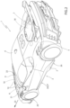
figures 1 and2 are two schematic perspective views, with parts removed for greater clarity, of a preferred embodiment of the vehicle according to the invention; and -
figure 3 is a schematic perspective view, with parts removed for greater clarity, of a detail of the vehicle offigures 1 and2 . - With reference to
figures 1 ,2 and3 ,number 1 indicates, as a whole, a vehicle, specifically a hybrid vehicle, comprising asupport frame 2 defining at least part of alower floor 3 of thevehicle 1, apassenger compartment 4 mounted on theframe 2 and projecting upwards from thefloor 3 and anouter body 5. - The
vehicle 1 further comprises a front compartment 6 obtained within thebody 5 and arear compartment 7 obtained within thebody 5. - The front compartment 6 is delimited by a
front bumper 8 and by afront hood 9 and accommodates, on the inside, afirst motor 10, specifically an electric motor, and afront radiator 11 to cool themotor 10. - The
radiator 11 is arranged along acentral duct 12, which extends inside the compartment 6 between thebumper 8 and thehood 9 and opens outwards both through thebumper 8 and through thehood 9. - The compartment 6 also houses, on the inside, two
side ducts 13, which are arranged on opposite sides of theduct 12, extend between thebumper 8 and thehood 9, are S-shaped and open outwards both through thebumper 8 and through thehood 9. - The
hood 9 has, in this case, twoopenings 14, each provided with a dividingpartition 15 defining twooutlet mouths mouth 16 being an inner mouth communicating with theduct 12 and themouth 17 being an outer mouth communicating with aduct 13. - In use, the air flow F flowing into the compartment 6 during the normal running of the
vehicle 1 is divided into a central air flow F1, which is supplied along theduct 12, through theradiator 11 and to themouths 16, and into two side air flows F2, which are supplied along therelative ducts 13 and to therelative mouths 17. - When flowing out of the
hood 9, the central air flow F1 is laterally delimited by the two side air flows F2, which do not flow through theradiator 11 and, therefore, have a lower temperature than a temperature of the central air flow F1. - The
rear compartment 7 houses, on the inside, asecond engine 18, specifically an internal combustion engine, a known and not shown turbocharger to supply compressed air to theengine 18 and at least one heat exchanger (not shown), commonly known as "intercooler", to cool the compressed air supplied by the turbocharger (not shown) to theengine 18. - The
vehicle 1 is further provided with a pair ofintake mouths 19, which are obtained between thepassenger compartment 4 and therear compartment 7 and open outwards through thebody 5 in the area of the side flanks of thevehicle 1 to supply air to the heat exchanger (not shown). - The
vehicle 1 further comprises a known air heating/conditioning system, which is not shown herein, to supply hot/conditioned air into thepassenger compartment 4, a first pair ofintake mouths 20 obtained under thehood 9 to supply air into thepassenger compartment 4 through the air heating/conditioning system and a second pair ofintake mouths 21 obtained along a lower edge of afront windshield 22 to supply air into thepassenger compartment 4 through the air heating/conditioning system. - The
mouths mouths mouths 17, measured crosswise to a forward movingdirection 23 of thevehicle 1, is smaller than the distance between themouths 19, the distance between themouths 20 and the distance between themouths 21, which are also measured crosswise to thedirection 23. - As a consequence, the air flows F2, namely the air flows at a lower temperature, extend between the
mouths mouths radiator 11 and of the aforesaid heat exchanger (not shown). - The
vehicle 1 finally comprises an aerodynamic bottom 24, which is fixed to theframe 2, defines part of thefloor 3 and comprises, in turn, afront bottom 25, which is mounted in the area of the front compartment 6, arear bottom 26, which is mounted in the area of therear compartment 7, and a central bottom 27, which is mounted in the area of thepassenger compartment 4. - At least the
front bottom 25 is closed so as to exert a relatively high vertical load upon thevehicle 1.
Claims (10)
- A vehicle comprising a support frame (2); a passenger compartment (4); an outer body (5); a front compartment (6) obtained within the outer body (5) and delimited by a front bumper (8) and by a front hood (9); a rear compartment (7) obtained within the outer body (5); a central duct (12), which extends between the front bumper (8) and the front hood (9) and opens outwards both through the front bumper (8) and through the front hood (9); and a front radiator (11) mounted in the front compartment (6) and along the central duct (12); and characterized in that it further comprises two side ducts (13), which are arranged on opposite sides of the central duct (12), extend between the front bumper (8) and the front hood (9) and open outwards both through the front bumper (8) and through the front hood (9) so as to confine a central air flow (F1) flowing along the central duct (12) between two side air flows (F2) flowing along the side ducts (13).
- The vehicle according to claim 1, wherein the two side ducts (13) are arranged on opposite sides of the front radiator (11).
- The vehicle according to claim 1 or 2, wherein each side duct (13) is substantially S-shaped.
- The vehicle according to any one of the preceding claims and further comprising at least one pair of first intake mouths (20, 21) to connect the passenger compartment (4) and the outside to one another and to allow environment air to flow into the passenger compartment (4); the first intake mouths (20, 21) of each pair of first intake mouths (20, 21) being obtained on the outside of the side ducts (13) .
- The vehicle according to claim 4 and further comprising an air heating/conditioning system interposed between the first intake mouths (20, 21) and the passenger compartment (4) in order to heat/condition the air flowing through the first intake mouths (20, 21).
- The vehicle according to any one of the preceding claims and further comprising a main engine (18), in particular an internal combustion engine, housed in the rear compartment (7), a compressor to supply compressed air to the main engine (18), at least one heat exchanger to cool the air supplied by the compressor to the main engine (18) and at least one pair of second intake mouths (19) obtained between the passenger compartment (4) and the rear compartment (7) in order to connect the heat exchanger and the outside to one another; the second intake mouths (19) of each pair of second intake mouths (19) being obtained on the outside of the side ducts (13).
- The vehicle according to any one of the preceding claims, wherein the front hood (9) has at least one central opening (16) for the passage of the central air flow (F1) and, for each side duct (13), a respective side opening (17) for the passage of the relative side air flow (F2).
- The vehicle according to claim 7, when it depends on claim 4 and/or 6, wherein the intake mouths (19, 20, 21) of each pair of intake mouths (19, 20, 21) are substantially symmetrical relative to a longitudinal symmetry plane of the vehicle and are arranged at a distance from one another, measured crosswise to a forward moving direction (23) of the vehicle, that is greater than a distance between the side openings (17), which is also measured crosswise to the forward moving direction (23).
- The vehicle according to any one of the preceding claims and further comprising an auxiliary motor (10), in particular an electric motor, associated with and cooled by the front radiator (11).
- The vehicle according to any one of the preceding claims, wherein the central duct (12) and the side ducts (13) extend through the front compartment (6).
Applications Claiming Priority (1)
| Application Number | Priority Date | Filing Date | Title |
|---|---|---|---|
| IT102023000012393A IT202300012393A1 (en) | 2023-06-16 | 2023-06-16 | VEHICLE WITH SIDE DUCTS FOR THE CONFINEMENT OF CENTRAL HOT FLOW |
Publications (2)
| Publication Number | Publication Date |
|---|---|
| EP4477441A1 true EP4477441A1 (en) | 2024-12-18 |
| EP4477441B1 EP4477441B1 (en) | 2026-03-04 |
Family
ID=88097794
Family Applications (1)
| Application Number | Title | Priority Date | Filing Date |
|---|---|---|---|
| EP24181307.0A Active EP4477441B1 (en) | 2023-06-16 | 2024-06-11 | Vehicle with side ducts for the confinement of a central hot flow |
Country Status (4)
| Country | Link |
|---|---|
| US (1) | US20240416743A1 (en) |
| EP (1) | EP4477441B1 (en) |
| CN (1) | CN119142109A (en) |
| IT (1) | IT202300012393A1 (en) |
Citations (3)
| Publication number | Priority date | Publication date | Assignee | Title |
|---|---|---|---|---|
| JP2005178427A (en) * | 2003-12-16 | 2005-07-07 | Calsonic Kansei Corp | Brake cooling structure for automobile |
| US20120318476A1 (en) * | 2011-06-20 | 2012-12-20 | GM Global Technology Operations LLC | Combined condensation radiator fan module and brake cooling duct shutter system |
| US10569643B2 (en) * | 2014-06-27 | 2020-02-25 | Compagnie Plastic Omnium | Motor vehicle front surface with central air inlet and side outlets |
Family Cites Families (12)
| Publication number | Priority date | Publication date | Assignee | Title |
|---|---|---|---|---|
| US5184832A (en) * | 1984-12-07 | 1993-02-09 | Tsutomu Miwa | Aerodynamic motorcar |
| FR2703632B1 (en) * | 1993-04-09 | 1995-05-24 | Valeo Thermique Habitacle | Heating-ventilation and / or air conditioning apparatus for a motor vehicle interior. |
| EP1348845A3 (en) * | 2002-03-26 | 2005-05-11 | Honda Giken Kogyo Kabushiki Kaisha | Engine cooling system for rear-engine vehicle |
| DE10242788B4 (en) * | 2002-09-14 | 2004-09-16 | Dr.Ing.H.C. F. Porsche Ag | Cooler arrangement with air ducts |
| DE102009031746A1 (en) * | 2009-07-06 | 2011-01-13 | GM Global Technology Operations, Inc., Detroit | Cooling air guiding device for a motor vehicle |
| US8479853B2 (en) * | 2011-05-17 | 2013-07-09 | GM Global Technology Operations LLC | Control of an airstream flow rate through a covered compartment by an adjustable shutter |
| IT201800002048A1 (en) * | 2018-01-26 | 2019-07-26 | Ferrari Spa | CAR WITH INCREASED FRONT AERODYNAMIC LOAD |
| JP7124559B2 (en) * | 2018-08-27 | 2022-08-24 | トヨタ自動車株式会社 | vehicle duct structure |
| USD918123S1 (en) * | 2019-02-27 | 2021-05-04 | Ferrari S.P.A. | Dashboard |
| JP7644893B2 (en) * | 2021-05-25 | 2025-03-13 | マツダ株式会社 | Vehicle front body structure |
| EP4328418B1 (en) * | 2022-08-25 | 2024-11-06 | FERRARI S.p.A. | Turbine assembly for an internal combustion engine |
| IT202300005865A1 (en) * | 2023-03-28 | 2024-09-28 | Ferrari Spa | MOTOR VEHICLE WITH AN IMPROVED ARRANGEMENT OF INTER-REFRIGERATORS FOR THE INTAKE AIR |
-
2023
- 2023-06-16 IT IT102023000012393A patent/IT202300012393A1/en unknown
-
2024
- 2024-06-10 US US18/738,611 patent/US20240416743A1/en active Pending
- 2024-06-11 EP EP24181307.0A patent/EP4477441B1/en active Active
- 2024-06-13 CN CN202410757300.8A patent/CN119142109A/en active Pending
Patent Citations (3)
| Publication number | Priority date | Publication date | Assignee | Title |
|---|---|---|---|---|
| JP2005178427A (en) * | 2003-12-16 | 2005-07-07 | Calsonic Kansei Corp | Brake cooling structure for automobile |
| US20120318476A1 (en) * | 2011-06-20 | 2012-12-20 | GM Global Technology Operations LLC | Combined condensation radiator fan module and brake cooling duct shutter system |
| US10569643B2 (en) * | 2014-06-27 | 2020-02-25 | Compagnie Plastic Omnium | Motor vehicle front surface with central air inlet and side outlets |
Also Published As
| Publication number | Publication date |
|---|---|
| CN119142109A (en) | 2024-12-17 |
| US20240416743A1 (en) | 2024-12-19 |
| IT202300012393A1 (en) | 2024-12-16 |
| EP4477441B1 (en) | 2026-03-04 |
Similar Documents
| Publication | Publication Date | Title |
|---|---|---|
| US11890923B2 (en) | Upper body heat exchanger for vehicles | |
| EP2602143B1 (en) | Cooling structure for vehicles | |
| US9738152B2 (en) | Airflow guiding system for vehicle | |
| EP2572918B1 (en) | Structure for introducing cooling air | |
| US11602985B2 (en) | Continuous cooling assembly | |
| US20090088062A1 (en) | Vehicle Body Pressure Relief System | |
| US11981195B2 (en) | Duct surface heat exchanger for vehicles | |
| US8701811B2 (en) | Battery cooling system and method | |
| EP2781390B1 (en) | Cooling wind introduction structure | |
| US20120318476A1 (en) | Combined condensation radiator fan module and brake cooling duct shutter system | |
| US10059193B2 (en) | Grille for a vehicle, in particular a commercial vehicle as well as a vehicle | |
| US20120222833A1 (en) | Active Louver System for Controlled Airflow in a Multi-Function Automotive Radiator and Condenser System | |
| JP2015160461A (en) | Air conditioner for vehicle | |
| US20180264912A1 (en) | Condenser unit of a roof-mounted air conditioning system | |
| EP4477441A1 (en) | Vehicle with side ducts for the confinement of a central hot flow | |
| CN117177873A (en) | Vehicles equipped with improved aerodynamic systems | |
| CN103963603A (en) | Heating, ventilation and air conditioning blowers | |
| US20220332171A1 (en) | Vehicle with air blowing vents carried by the front seats | |
| KR102518553B1 (en) | Aerodynamic apparatus for vehicle | |
| CN106159372B (en) | Battery pack temperature-adjusting device | |
| JP7524749B2 (en) | Vehicle front structure | |
| KR20250014397A (en) | Rear Seat Air Conditioning System for Electric Vehicles | |
| JP2008508459A (en) | Cooling system | |
| CN120792412A (en) | Vehicle HVAC system for operating with passenger cabin heat | |
| CN111070995A (en) | Air intake device for vehicle HVAC system |
Legal Events
| Date | Code | Title | Description |
|---|---|---|---|
| PUAI | Public reference made under article 153(3) epc to a published international application that has entered the european phase |
Free format text: ORIGINAL CODE: 0009012 |
|
| STAA | Information on the status of an ep patent application or granted ep patent |
Free format text: STATUS: THE APPLICATION HAS BEEN PUBLISHED |
|
| AK | Designated contracting states |
Kind code of ref document: A1 Designated state(s): AL AT BE BG CH CY CZ DE DK EE ES FI FR GB GR HR HU IE IS IT LI LT LU LV MC ME MK MT NL NO PL PT RO RS SE SI SK SM TR |
|
| STAA | Information on the status of an ep patent application or granted ep patent |
Free format text: STATUS: REQUEST FOR EXAMINATION WAS MADE |
|
| 17P | Request for examination filed |
Effective date: 20250527 |
|
| GRAP | Despatch of communication of intention to grant a patent |
Free format text: ORIGINAL CODE: EPIDOSNIGR1 |
|
| STAA | Information on the status of an ep patent application or granted ep patent |
Free format text: STATUS: GRANT OF PATENT IS INTENDED |
|
| RIC1 | Information provided on ipc code assigned before grant |
Ipc: B60K 13/02 20060101AFI20250915BHEP Ipc: B60K 11/02 20060101ALI20250915BHEP Ipc: B60K 13/06 20060101ALI20250915BHEP Ipc: B60K 11/08 20060101ALN20250915BHEP |
|
| INTG | Intention to grant announced |
Effective date: 20250929 |
|
| GRAS | Grant fee paid |
Free format text: ORIGINAL CODE: EPIDOSNIGR3 |
|
| GRAA | (expected) grant |
Free format text: ORIGINAL CODE: 0009210 |
|
| STAA | Information on the status of an ep patent application or granted ep patent |
Free format text: STATUS: THE PATENT HAS BEEN GRANTED |
|
| AK | Designated contracting states |
Kind code of ref document: B1 Designated state(s): AL AT BE BG CH CY CZ DE DK EE ES FI FR GB GR HR HU IE IS IT LI LT LU LV MC ME MK MT NL NO PL PT RO RS SE SI SK SM TR |
|
| REG | Reference to a national code |
Ref country code: CH Ref legal event code: F10 Free format text: ST27 STATUS EVENT CODE: U-0-0-F10-F00 (AS PROVIDED BY THE NATIONAL OFFICE) Effective date: 20260304 Ref country code: GB Ref legal event code: FG4D |
|
| REG | Reference to a national code |
Ref country code: IE Ref legal event code: FG4D |
|
| REG | Reference to a national code |
Ref country code: DE Ref legal event code: R096 Ref document number: 602024002948 Country of ref document: DE |