EP4477432A1 - Tire with a set of printed sensors - Google Patents
Tire with a set of printed sensors Download PDFInfo
- Publication number
- EP4477432A1 EP4477432A1 EP24181535.6A EP24181535A EP4477432A1 EP 4477432 A1 EP4477432 A1 EP 4477432A1 EP 24181535 A EP24181535 A EP 24181535A EP 4477432 A1 EP4477432 A1 EP 4477432A1
- Authority
- EP
- European Patent Office
- Prior art keywords
- sensors
- tire
- sidewall
- printed
- previous
- Prior art date
- Legal status (The legal status is an assumption and is not a legal conclusion. Google has not performed a legal analysis and makes no representation as to the accuracy of the status listed.)
- Granted
Links
Images




Classifications
-
- B—PERFORMING OPERATIONS; TRANSPORTING
- B60—VEHICLES IN GENERAL
- B60C—VEHICLE TYRES; TYRE INFLATION; TYRE CHANGING; CONNECTING VALVES TO INFLATABLE ELASTIC BODIES IN GENERAL; DEVICES OR ARRANGEMENTS RELATED TO TYRES
- B60C23/00—Devices for measuring, signalling, controlling, or distributing tyre pressure or temperature, specially adapted for mounting on vehicles; Arrangement of tyre inflating devices on vehicles, e.g. of pumps or of tanks; Tyre cooling arrangements
- B60C23/02—Signalling devices actuated by tyre pressure
- B60C23/04—Signalling devices actuated by tyre pressure mounted on the wheel or tyre
- B60C23/0408—Signalling devices actuated by tyre pressure mounted on the wheel or tyre transmitting the signals by non-mechanical means from the wheel or tyre to a vehicle body mounted receiver
- B60C23/0422—Signalling devices actuated by tyre pressure mounted on the wheel or tyre transmitting the signals by non-mechanical means from the wheel or tyre to a vehicle body mounted receiver characterised by the type of signal transmission means
-
- B—PERFORMING OPERATIONS; TRANSPORTING
- B60—VEHICLES IN GENERAL
- B60C—VEHICLE TYRES; TYRE INFLATION; TYRE CHANGING; CONNECTING VALVES TO INFLATABLE ELASTIC BODIES IN GENERAL; DEVICES OR ARRANGEMENTS RELATED TO TYRES
- B60C23/00—Devices for measuring, signalling, controlling, or distributing tyre pressure or temperature, specially adapted for mounting on vehicles; Arrangement of tyre inflating devices on vehicles, e.g. of pumps or of tanks; Tyre cooling arrangements
- B60C23/06—Signalling devices actuated by deformation of the tyre, e.g. tyre mounted deformation sensors or indirect determination of tyre deformation based on wheel speed, wheel-centre to ground distance or inclination of wheel axle
- B60C23/064—Signalling devices actuated by deformation of the tyre, e.g. tyre mounted deformation sensors or indirect determination of tyre deformation based on wheel speed, wheel-centre to ground distance or inclination of wheel axle comprising tyre mounted deformation sensors, e.g. to determine road contact area
-
- G—PHYSICS
- G01—MEASURING; TESTING
- G01L—MEASURING FORCE, STRESS, TORQUE, WORK, MECHANICAL POWER, MECHANICAL EFFICIENCY, OR FLUID PRESSURE
- G01L17/00—Devices or apparatus for measuring tyre pressure or the pressure in other inflated bodies
- G01L17/005—Devices or apparatus for measuring tyre pressure or the pressure in other inflated bodies using a sensor contacting the exterior surface, e.g. for measuring deformation
-
- B—PERFORMING OPERATIONS; TRANSPORTING
- B60—VEHICLES IN GENERAL
- B60C—VEHICLE TYRES; TYRE INFLATION; TYRE CHANGING; CONNECTING VALVES TO INFLATABLE ELASTIC BODIES IN GENERAL; DEVICES OR ARRANGEMENTS RELATED TO TYRES
- B60C23/00—Devices for measuring, signalling, controlling, or distributing tyre pressure or temperature, specially adapted for mounting on vehicles; Arrangement of tyre inflating devices on vehicles, e.g. of pumps or of tanks; Tyre cooling arrangements
- B60C23/02—Signalling devices actuated by tyre pressure
- B60C23/04—Signalling devices actuated by tyre pressure mounted on the wheel or tyre
- B60C23/0491—Constructional details of means for attaching the control device
- B60C23/0493—Constructional details of means for attaching the control device for attachment on the tyre
Definitions
- the invention relates to tires. More particularly, the invention relates to tires with sensors that sense various conditions within a tire. Specifically, the invention is directed to a tire that includes a set of sensors (e.g. shear and/or strain sensors) which are arranged on the innerliner of the tire that enables accurate determination of e.g. vertical load, longitudinal force, lateral force, dynamic rolling and/or cornering conditions on/of the tire.
- sensors e.g. shear and/or strain sensors
- the tire In the manufacture of a pneumatic tire, the tire is typically built on the drum of a tire-building machine, which is known in the art as a tire building drum. Numerous tire components are wrapped about and/or applied to the drum in sequence, forming a cylindrical-shaped tire carcass. The tire carcass is then expanded into a toroidal shape for receipt of the remaining components of the tire, such as a belt package and a rubber tread. The completed toroidally-shaped unvulcanized tire carcass, which is known in the art at that stage as a green tire, is then inserted into a mold or press for forming of the tread pattern and curing or vulcanization.
- Such electronic components enable certain tire parameters to be monitored.
- discrete electronic sensor units have been attached to the inside surface of the pneumatic tire, which is known as the tire innerliner, using an adhesive.
- Such sensors measure deformation of the sidewall of the tire to provide data which can be used to determine the load on the tire.
- data can be communicated to vehicle stability and/or braking systems to provide improved control of the vehicle, and can be used for monitoring or tracking driving behavior.
- prior art discrete electronic sensor units are acceptable for their intended purpose, it is desirable to improve the accuracy of measurements of tire sidewall deformation to determine different (e.g. load) conditions on the tire in a more precise and repeatable manner.
- typical prior art deformation sensor units include a long, thin strip of conductive material arranged to form a zig-zag pattern of parallel lines, which is attached to a substrate material. An excitation voltage is applied to terminal ends of the strip and electrical resistance is then measured. The deformation of the tire at the location of the sensor may be calculated from the measured resistance, as known to those skilled in the art.
- Other deformation sensors known in the art involve measuring electrical capacitance of the conductive material or using optical fibers.
- a first preferred aspect of the invention relates to a tire with printed sensors, comprising a pair of bead areas, a ground-contacting tread disposed radially outwardly of the pair of bead areas, a pair of sidewalls, including an inboard sidewall extending from a first one of the bead areas to the tread, and an outboard sidewall extending from a second one of the bead areas to the tread.
- the tire further comprises a carcass extending toroidally between each of the bead areas radially inwardly of the tread and an innerliner formed on an inside surface of the carcass.
- the tire comprises a set of sensors consisting of a plurality of sensors printed on the innerliner, wherein the plurality of sensors are printed in a sidewall zone of the inboard sidewall or in a sidewall zone of the outboard sidewall, the plurality of sensors being configured to measure deformation in the sidewall zone, the plurality of sensors being daisy-chained so that the set of sensors provides a single deformation signal, the single deformation signal being based on the measured deformations of the plurality of sensors.
- a second preferred aspect of the present invention relates to a tire with printed sensors comprising a pair of bead areas, a ground-contacting tread disposed radially outwardly of the pair of bead areas, a pair of sidewalls, including an inboard sidewall extending from a first one of the bead areas to the tread, and an outboard sidewall extending from a second one of the bead areas to the tread.
- the tire further comprises a carcass extending toroidally between each of the bead areas radially inwardly of the tread and an innerliner formed on an inside surface of the carcass.
- the tire comprises a first set of sensors consisting of a plurality of sensors printed on the innerliner, wherein the plurality of sensors are printed in a sidewall zone of the inboard sidewall, a second set of sensors consisting of a plurality of sensors printed on the innerliner, wherein the plurality of sensors are printed in a sidewall zone of the outboard sidewall.
- the plurality of sensors of both the first and second set of sensors are configured to measure deformation in the respective sidewall zones of the inboard sidewall and of the outboard sidewall, and the plurality of sensors of each of the first and second set of sensors are daisy-chained so that the respective set of sensors provide first and second single deformation signals, the single deformation signals being the combination of the measured deformations of the respective plurality of sensors.
- rubber is intended to include both natural rubber compositions and synthetic rubber compositions.
- specific examples of rubbers include neoprene (polychloroprene), polybutadiene (e.g., cis-1,4-polybutadiene), polyisoprene (e.g., cis-1,4-polyisoprene), butyl rubber, halobutyl rubber (such as, e.g., chlorobutyl rubber or bromobutyl rubber), styrene/isoprene/butadiene rubber, copolymers of 1,3-butadiene or isoprene with monomers such as, e.g., styrene, acrylonitrile and methyl methacrylate.
- Other types of rubber include carboxylated rubber, silicon-coupled rubber, or tin-coupled star-branched polymers. Rubber may include (or consist of) green rubber.
- Axial and “axially” mean lines or directions that are parallel to the axis of rotation of the tire.
- Bead means that part of the tire comprising an annular tensile member wrapped by ply cords and shaped, with or without other reinforcement elements such as flippers, chippers, apexes, toe guards and chafers, to fit the design rim.
- Carcass means the tire structure apart from the belt structure, tread, undertread, and sidewall rubber over the plies, but including the beads.
- “Circumferential” means lines or directions extending along the perimeter of the surface of the annular tread perpendicular to the axial direction.
- Core means one of the reinforcement strands of which the plies in the tire are comprised.
- Equatorial plane means the plane perpendicular to the tire's axis of rotation and passing through the center of its tread.
- Innerliner means the layer or layers of elastomer or other material that form the inside surface of a tubeless tire and that contain the inflating fluid within the tire.
- Ring and radially mean lines or directions that are perpendicular to the axis of rotation of the tire.
- Ring-ply tire means a belted or circumferentially-restricted pneumatic tire in which the ply cords which extend from bead to bead are laid at cord angles between about 65 to about 90 degrees with respect to the equatorial plane of the tire.
- TPMS means a tire pressure monitoring system, which is an electronic system that measures the internal pressure of a tire and is capable of communicating the pressure to a processor that is mounted on the vehicle and/or is in electronic communication with electronic systems of the vehicle.
- “Daisy chaining” means connecting (e.g. wiring) multiple devices are wired together in sequence (in series).
- FIG. 1 An exemplary embodiment of a tire 10 is shown in FIG. 1 .
- the tire 10 includes a pair of bead areas 12, each one of which is formed with a bead core 14 that is embedded in the respective bead areas.
- Each one of a pair of sidewalls 16 extends radially outward from a respective bead area 12 to a ground-contacting tread 18.
- the tire 10 is reinforced by a carcass 20 that toroidally extends from one bead area, such as an inboard bead area 12a, to the other bead area, such as an outboard bead area 12b, also as known to those skilled in the art.
- the carcass includes multiple layers or plies, as known to those skilled in the art.
- An innerliner 22 is formed on the inner or inside surface of the carcass 20.
- the tire 10 is mounted on the flange 24 of a wheel or rim 26, as known in the art.
- the tire 10 includes an inboard surface (i.e. non serial side) indicated generally by the letter "a” and an outboard surface (i.e. serial side) indicated generally by the letter "b".
- components at the tire inboard surface are denoted with an "a” designation and components at the tire outboard surface are denoted with a "b” designation.
- the sidewall 16 at the inboard surface "a” of the tire 10 is an inboard sidewall 16a
- the sidewall at the outboard surface "b" of the tire is an outboard sidewall 16b.
- the tire 10 includes three perpendicular axes upon which forces act, including a "Y" axis extending in the axial or lateral direction, a “Z” axis extending in the radial or vertical direction, and an "X" axis extending in the longitudinal direction or direction of the travel of the tire.
- the tire 10 also includes three zones with different levels of rigidity.
- a first or apex zone 28 is disposed at each respective bead area 12
- a second or crown zone 30 is disposed at the tread 18, and
- a third or sidewall zone 32 is disposed at each respective sidewall 16 between the apex and crown zones.
- the sidewall zone 32 typically is less rigid and thus deforms more during rotation of the tire 10 than the apex zone 28 and the crown zone 30. As a result, measurement of deformation at the sidewall zone 32 is important.
- the tire 10 in order to provide accurate and repeatable measurement of deformation at the sidewall zone 32, the tire 10 includes a first or inboard sensor 34.
- the inboard sensor 34 preferably is printed on the innerliner 22 at the sidewall zone 32 of the inboard sidewall 16a.
- the tire 10 also includes a second or outboard sensor 36.
- the outboard sensor 36 preferably is printed on the innerliner 22 at the sidewall zone 32 of the outboard sidewall 16b.
- the sensors 34 and 36 measure the deformation of the innerliner 22 at the sidewall zone 32 of each respective sidewall 16a and 16b, enabling the vertical loading of the tire 10 as well as the lateral force and the longitudinal force acting on the tire 10 to be determined.
- the sensors 34 and 36 may be disposed in the same horizontal plane 38 extending laterally across the tire 10, and preferably are in (wired or wireless) communication with a TPMS unit 40, e.g. via wires or an antenna.
- the TPMS unit 40 preferably is attached to the innerliner 22 by an adhesive or other means known to those skilled in the art.
- the TPMS unit 40 typically includes an internal processor and an antenna or other communication means for communicating data to an external processor and/or to the local electronic device network or Controller Area Network (CAN bus) of the vehicle on which the tire 10 is mounted.
- CAN bus Controller Area Network
- tire 10 includes a plurality of sensors indicated at 34a through 34p arranged, preferably printed, on the tire innerliner 22 ( FIG. 1 ) in the sidewall zone 32 of the inboard sidewall 16a about the circumference of the tire 10.
- the sensors 34a through 34p preferably are evenly spaced apart, with an angular step or distance 130 between them.
- the sensors 34a-34p may cover the (substantially) entire surface of the sidewall zone 32.
- the tire also includes another plurality of sensors 36a through 36p arranged, preferably printed, on the tire innerliner 22 in the sidewall zone 32 of the outboard sidewall 16b about the circumference of the tire 10.
- the sensors of the other plurality of sensors may equally be evenly spaced apart, with an angular step or distance between them.
- the characteristics of the plurality of sensors34a to 34p may equally be applicable to the other plurality of sensors.
- the plurality of sensors 34a to 34p are daisy-chained (e.g. by wires) so that the set of sensors provides a single (electrical) deformation signal between terminals 37 and 39.
- the single deformation signal is, by design, based on the measured deformations of the plurality of sensors, in particular, it is the sum of the measured deformations of the plurality of sensors.
- the TPMS unit 40 may thus receive the single (electrical) deformation signals from the sensors 34a-p and 36a-p and employ its processor to calculate the vertical loading, the lateral force and the longitudinal force acting on or of the tire 10, and transmit the calculated data to the vehicle control systems through the CAN bus (Controller Area Network bus).
- the TPMS unit 40 may transmit the single (electrical) deformation signal from the sensors 34a-p and 36a-p to an external processor for the calculation of the vertical loading, the lateral force and the longitudinal force acting on or of the tire 10, followed by transmission of the calculated data to the vehicle control systems through the CAN bus.
- Each sensor preferably is directly printed on the innerliner 22 at the sidewall zone 32 of each respective inboard sidewall 16a and outboard sidewall 16b by ink-jet printing or by three-dimensional (3D) printing.
- the specific configuration and location of each sensor in the sidewall zone 32 depends upon the construction and size of the tire 10.
- Each sensor may be printed using a conductive ink 42 with a known electrical resistance, and which is flexible.
- the printing of each of the sensors 34a-p and 36a-p on the innerliner 22 is performed according to inkjet printing or 3D printing techniques that are known to those skilled in the art.
- each sensor may be printed on a discrete substrate such as foil, rubber, plastic or a combination thereof.
- the substrate is of a flexible and soft rubber-foil compound that has a short relaxation time, which enables each sensor to sense deformation of the tire 10.
- the combination substrate and the sensor may be attached to the innerliner at the sidewall zone 32 of each respective inboard sidewall 16a and outboard sidewall 16b using an adhesive, ultrasonic welding, or other techniques known to those skilled in the art. Stability of the conductive ink 42 over a range of temperatures enables attachment of the substrate and sensor 34 and 36 to the innerliner 22 before curing of the tire 10 or after curing of the tire. Installing a substrate and the sensor on an after-cured tire 10 enables each sensor to be manufactured independently of the tire and provides independent quality control for the sensors separate from the tire.
- the sensors may be shear sensors or strain sensors.
- FIG. 5 shows such a shear sensor.
- the conductive ink 42 is deposited in a long, thin strip arranged to form a first set of parallel elements 44, a second set of parallel elements 46 and a plurality of terminals 48A through 48D.
- the first set of parallel elements 44 is oriented at a first angle 50 relative to the Z axis
- the second set of parallel elements 46 is oriented at a second angle 52 relative to the Z axis that is the opposite or negative of the first angle.
- the first angle 50 is about 45 degrees relative to the Z axis and the second angle 52 is about -45 degrees relative to the Z axis.
- a first terminal 48A provides a connection to the first set of parallel elements 44 and a fourth terminal 48D provides a connection to the second set of parallel elements 46.
- a second terminal 48B is disposed parallel to the Z axis between the first set of parallel elements 44 and the second set of parallel elements 46, and a third terminal 48C is disposed parallel to the Z axis between the second terminal and the fourth terminal 48D.
- the first set of parallel elements 44 provides a signal in a positive direction along the X axis and Z axis direction, which is referred to as positive shear.
- the second set of parallel elements 46 provides a signal in a negative direction along the X axis and Z axis direction, which is referred to as negative shear.
- Each shear sensor is capable of delivering at least three signals.
- a first signal, 48A:48B is a positive shear signal, which is a measurement of shear strain between the first terminal 48A and the second terminal 48B.
- a second signal, 48B:48D is a negative shear strain signal, which is a measurement of shear strain between the second terminal 48B and the fourth terminal 48D.
- a third signal, 48B:48C is a reference signal that is a measurement between the second terminal 48B and the third terminal 48C, which are both parallel to the Z axis.
- the shear sensors may be daisy-chained in such a way that terminal 48A of a first sensor is connected to terminal 48D of an adjacent sensor. All the sensors of a set of sensors are connected in such way so that only one terminal 48A and only one terminal 48D remain unconnected to another sensor.
- the two remaining terminals provide the single deformation signal being a single shear deformation signal.
- Such single deformation signal may be provided to the TPMS via wires or possible wireless communication (e.g. RF or Bluetooth low energy).
- daisy-chaining terminals 48B and 48C in the same way as for terminals 48A and 48D is also possible so as to provide a reference signal.
- strain sensors In case of strain sensors being used, strain sensors disclosed e.g. in US 10,953,710 re suitable.
- conductive ink 54 is deposited in a long, thin strip arranged to form a zigzag pattern of parallel elements 56 with a plurality of terminals 58 and a perpendicular element 60.
- the arrangement of parallel elements 56 increases the sensitivity of each sensor 34 and 36 in a specific direction or axis indicated by arrow D, which extends parallel to the parallel elements and is referred to herein as the sensitive axis.
- the plurality of terminals 58 preferably includes a first terminal 58A, a second terminal 58B and a third terminal 58C.
- the perpendicular element 60 extends from the first terminal 58A in a direction perpendicular to the sensitive axis D.
- the zigzag pattern of elements 56 extends between the second terminal 58B and the third terminal 58C.
- each sensor 34 and 36 provides or delivers signals as determined by the arrangement of the elements 56 and the terminals 58.
- the first signal of each sensor 34 and 36 referred to herein as 58B:58C, is a measurement of strain between a first end of the zigzag pattern of elements 56 at the second terminal 58B and a second end of the zigzag pattern of elements at the third terminal 58C.
- the second signal of each sensor 34 and 36 referred to as 58A:58B, is a reference signal, which is a measurement between the perpendicular element 60 the first terminal 58A and the first end of the zigzag pattern of elements at the second terminal 58B.
- the first signal 58B:58C and the second signal 58A:58B are both proportional to the resistivity of the ink 54.
- the strain sensors may be daisy-chained in such a way that terminal 58B of a first sensor is connected to terminal 58C of an adjacent sensor. All the sensors of a set of sensors are connected in such way so that only one terminal 58B and only one terminal 58C remain unconnected to another sensors.
- the two remaining terminals provide the single deformation signal being a single shear deformation signal.
- Such single deformation signal may be provided to the TPMS via wires or possible wireless communication (e.g. RF or Bluetooth low energy).
- the TPMS may be configured to compute a dynamic vertical tire load based on a sum of the first and second single deformation signals. Also the TPMS may be configured to compute a cornering condition based on a difference between the first and second single deformation signals. Alternatively or additionally, as explained above, the single deformation signals may be transmitted remotely for a remote processing of the signals in order to determine said dynamic vertical tire load and/or said cornering condition.
Landscapes
- Engineering & Computer Science (AREA)
- Mechanical Engineering (AREA)
- Chemical & Material Sciences (AREA)
- Analytical Chemistry (AREA)
- Physics & Mathematics (AREA)
- General Physics & Mathematics (AREA)
- Tires In General (AREA)
Abstract
Description
- The invention relates to tires. More particularly, the invention relates to tires with sensors that sense various conditions within a tire. Specifically, the invention is directed to a tire that includes a set of sensors (e.g. shear and/or strain sensors) which are arranged on the innerliner of the tire that enables accurate determination of e.g. vertical load, longitudinal force, lateral force, dynamic rolling and/or cornering conditions on/of the tire.
- In the manufacture of a pneumatic tire, the tire is typically built on the drum of a tire-building machine, which is known in the art as a tire building drum. Numerous tire components are wrapped about and/or applied to the drum in sequence, forming a cylindrical-shaped tire carcass. The tire carcass is then expanded into a toroidal shape for receipt of the remaining components of the tire, such as a belt package and a rubber tread. The completed toroidally-shaped unvulcanized tire carcass, which is known in the art at that stage as a green tire, is then inserted into a mold or press for forming of the tread pattern and curing or vulcanization.
- It may often be desirable to mount electronic components to the tires either before or after curing. Such electronic components enable certain tire parameters to be monitored. For example, in the prior art, discrete electronic sensor units have been attached to the inside surface of the pneumatic tire, which is known as the tire innerliner, using an adhesive. Such sensors measure deformation of the sidewall of the tire to provide data which can be used to determine the load on the tire. Such data can be communicated to vehicle stability and/or braking systems to provide improved control of the vehicle, and can be used for monitoring or tracking driving behavior.
- While prior art discrete electronic sensor units are acceptable for their intended purpose, it is desirable to improve the accuracy of measurements of tire sidewall deformation to determine different (e.g. load) conditions on the tire in a more precise and repeatable manner. By way of background, typical prior art deformation sensor units include a long, thin strip of conductive material arranged to form a zig-zag pattern of parallel lines, which is attached to a substrate material. An excitation voltage is applied to terminal ends of the strip and electrical resistance is then measured. The deformation of the tire at the location of the sensor may be calculated from the measured resistance, as known to those skilled in the art. Other deformation sensors known in the art involve measuring electrical capacitance of the conductive material or using optical fibers.
- The present invention is defined by the scope of the independent claim. Preferred embodiments are defined by the dependent claims.
- A first preferred aspect of the invention relates to a tire with printed sensors, comprising a pair of bead areas, a ground-contacting tread disposed radially outwardly of the pair of bead areas, a pair of sidewalls, including an inboard sidewall extending from a first one of the bead areas to the tread, and an outboard sidewall extending from a second one of the bead areas to the tread. The tire further comprises a carcass extending toroidally between each of the bead areas radially inwardly of the tread and an innerliner formed on an inside surface of the carcass. In addition, the tire comprises a set of sensors consisting of a plurality of sensors printed on the innerliner, wherein the plurality of sensors are printed in a sidewall zone of the inboard sidewall or in a sidewall zone of the outboard sidewall, the plurality of sensors being configured to measure deformation in the sidewall zone, the plurality of sensors being daisy-chained so that the set of sensors provides a single deformation signal, the single deformation signal being based on the measured deformations of the plurality of sensors.
- A second preferred aspect of the present invention relates to a tire with printed sensors comprising a pair of bead areas, a ground-contacting tread disposed radially outwardly of the pair of bead areas, a pair of sidewalls, including an inboard sidewall extending from a first one of the bead areas to the tread, and an outboard sidewall extending from a second one of the bead areas to the tread. The tire further comprises a carcass extending toroidally between each of the bead areas radially inwardly of the tread and an innerliner formed on an inside surface of the carcass. In addition, the tire comprises a first set of sensors consisting of a plurality of sensors printed on the innerliner, wherein the plurality of sensors are printed in a sidewall zone of the inboard sidewall, a second set of sensors consisting of a plurality of sensors printed on the innerliner, wherein the plurality of sensors are printed in a sidewall zone of the outboard sidewall. The plurality of sensors of both the first and second set of sensors are configured to measure deformation in the respective sidewall zones of the inboard sidewall and of the outboard sidewall, and the plurality of sensors of each of the first and second set of sensors are daisy-chained so that the respective set of sensors provide first and second single deformation signals, the single deformation signals being the combination of the measured deformations of the respective plurality of sensors.
- In the present documents, several embodiments are described. It is worthwhile noting that each feature described for a particular embodiment of an aspect of the invention may be equally applied to another aspect of the invention.
- As used herein, the term "rubber" is intended to include both natural rubber compositions and synthetic rubber compositions. Specific examples of rubbers include neoprene (polychloroprene), polybutadiene (e.g., cis-1,4-polybutadiene), polyisoprene (e.g., cis-1,4-polyisoprene), butyl rubber, halobutyl rubber (such as, e.g., chlorobutyl rubber or bromobutyl rubber), styrene/isoprene/butadiene rubber, copolymers of 1,3-butadiene or isoprene with monomers such as, e.g., styrene, acrylonitrile and methyl methacrylate. Other types of rubber include carboxylated rubber, silicon-coupled rubber, or tin-coupled star-branched polymers. Rubber may include (or consist of) green rubber.
- "Axial" and "axially" mean lines or directions that are parallel to the axis of rotation of the tire.
- "Axially inward" and "axially inwardly" refer to an axial direction that is toward the axial center of the tire.
- "Axially outward" and "axially outwardly" refer to an axial direction that is away from the axial center of the tire.
- "Bead" means that part of the tire comprising an annular tensile member wrapped by ply cords and shaped, with or without other reinforcement elements such as flippers, chippers, apexes, toe guards and chafers, to fit the design rim.
- "Carcass" means the tire structure apart from the belt structure, tread, undertread, and sidewall rubber over the plies, but including the beads.
- "Circumferential" means lines or directions extending along the perimeter of the surface of the annular tread perpendicular to the axial direction.
- "Cord" means one of the reinforcement strands of which the plies in the tire are comprised.
- "Equatorial plane (EP)" means the plane perpendicular to the tire's axis of rotation and passing through the center of its tread.
- "Innerliner" means the layer or layers of elastomer or other material that form the inside surface of a tubeless tire and that contain the inflating fluid within the tire.
- "Radial" and "radially" mean lines or directions that are perpendicular to the axis of rotation of the tire.
- "Radially inward" and "radially inwardly" refer to a radial direction that is toward the central axis of rotation of the tire.
- "Radially outward" and "radially outwardly" refer to a radial direction that is away from the central axis of rotation of the tire.
- "Radial-ply tire" means a belted or circumferentially-restricted pneumatic tire in which the ply cords which extend from bead to bead are laid at cord angles between about 65 to about 90 degrees with respect to the equatorial plane of the tire.
- "TPMS" means a tire pressure monitoring system, which is an electronic system that measures the internal pressure of a tire and is capable of communicating the pressure to a processor that is mounted on the vehicle and/or is in electronic communication with electronic systems of the vehicle.
- "Daisy chaining" means connecting (e.g. wiring) multiple devices are wired together in sequence (in series).
- In the present document, the verb "to comprise" and the expression "to be comprised of" are used as open transitional phrases meaning "to include" or "to consist at least of". Unless otherwise implied by context, the use of singular word form is intended to encompass the plural, except when the cardinal number "one" is used: "one" herein means "exactly one". Ordinal numbers ("first", "second", etc.) are used herein to differentiate between different instances of a generic object; no particular order, importance or hierarchy is intended to be implied by the use of these expressions. Furthermore, when plural instances of an object are referred to by ordinal numbers, this does not necessarily mean that no other instances of that object are present (unless this follows clearly from context). When reference is made to "an embodiment", "one embodiment", "embodiments", etc., this means that these embodiments may be combined with one another. Furthermore, the features of those embodiments can be used in the combination explicitly presented but also that the features can be combined across embodiments without departing from the invention, unless it follows from context that features cannot be combined.
- The invention will be described by way of example and with reference to the accompanying drawings in which:
-
FIG. 1 is a schematic cross-sectional view of a portion of an exemplary embodiment of a tire prior to the forming of sensors on the innerliner, shown mounted on a wheel; -
FIG. 2 s is a schematic cross-sectional view of a portion of the tire shown inFIG. 1 with printed sensors formed on the innerliner, comprising an exemplary embodiment of a tire with printed sensors of the present invention; -
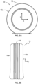
FIG. 3a is a schematic representation of an outboard side of the tire shown inFIG. 2 ; -
FIG. 3b is a schematic representation of an end view of the tire shown inFIG. 3a ; -
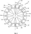
FIG. 4 is a schematic representation of an outboard side of another exemplary embodiment of a tire with printed sensors of the present invention, shown mounted on a wheel; -
FIG. 5 is a schematic representation of an exemplary embodiment of a printed shear sensor for the tire shown inFIG. 2 and/orFIG. 4 ; and -
FIG. 6 is a schematic representation of an exemplary embodiment of a printed strain sensor for the tire shown inFIG. 2 and/orFIG. 4 . - The reader's attention is drawn to the fact that the drawings are not to scale. Furthermore, for the sake of clarity, proportions between height, length and/or width may not have been represented correctly.
- Preferred embodiments of the present inventions are described herebelow.
- An exemplary embodiment of a
tire 10 is shown inFIG. 1 . Thetire 10 includes a pair ofbead areas 12, each one of which is formed with abead core 14 that is embedded in the respective bead areas. Each one of a pair ofsidewalls 16 extends radially outward from arespective bead area 12 to a ground-contactingtread 18. Thetire 10 is reinforced by acarcass 20 that toroidally extends from one bead area, such as an inboard bead area 12a, to the other bead area, such as an outboard bead area 12b, also as known to those skilled in the art. The carcass includes multiple layers or plies, as known to those skilled in the art. Aninnerliner 22 is formed on the inner or inside surface of thecarcass 20. Thetire 10 is mounted on theflange 24 of a wheel orrim 26, as known in the art. - The
tire 10 includes an inboard surface (i.e. non serial side) indicated generally by the letter "a" and an outboard surface (i.e. serial side) indicated generally by the letter "b". As a result, components at the tire inboard surface are denoted with an "a" designation and components at the tire outboard surface are denoted with a "b" designation. For example, thesidewall 16 at the inboard surface "a" of thetire 10 is aninboard sidewall 16a, and the sidewall at the outboard surface "b" of the tire is anoutboard sidewall 16b. - With reference to
Figs. 3a and 3b , thetire 10 includes three perpendicular axes upon which forces act, including a "Y" axis extending in the axial or lateral direction, a "Z" axis extending in the radial or vertical direction, and an "X" axis extending in the longitudinal direction or direction of the travel of the tire. - The
tire 10 also includes three zones with different levels of rigidity. A first orapex zone 28 is disposed at eachrespective bead area 12, a second orcrown zone 30 is disposed at thetread 18, and a third orsidewall zone 32 is disposed at eachrespective sidewall 16 between the apex and crown zones. Thesidewall zone 32 typically is less rigid and thus deforms more during rotation of thetire 10 than theapex zone 28 and thecrown zone 30. As a result, measurement of deformation at thesidewall zone 32 is important. - Turning to
FIG. 2 , in order to provide accurate and repeatable measurement of deformation at thesidewall zone 32, thetire 10 includes a first orinboard sensor 34. Theinboard sensor 34 preferably is printed on theinnerliner 22 at thesidewall zone 32 of theinboard sidewall 16a. Thetire 10 also includes a second oroutboard sensor 36. Theoutboard sensor 36 preferably is printed on theinnerliner 22 at thesidewall zone 32 of theoutboard sidewall 16b. Thesensors innerliner 22 at thesidewall zone 32 of eachrespective sidewall tire 10 as well as the lateral force and the longitudinal force acting on thetire 10 to be determined. - The
sensors horizontal plane 38 extending laterally across thetire 10, and preferably are in (wired or wireless) communication with aTPMS unit 40, e.g. via wires or an antenna. TheTPMS unit 40 preferably is attached to theinnerliner 22 by an adhesive or other means known to those skilled in the art. TheTPMS unit 40 typically includes an internal processor and an antenna or other communication means for communicating data to an external processor and/or to the local electronic device network or Controller Area Network (CAN bus) of the vehicle on which thetire 10 is mounted. - Turning now to
FIG. 4 ,tire 10 includes a plurality of sensors indicated at 34a through 34p arranged, preferably printed, on the tire innerliner 22 (FIG. 1 ) in thesidewall zone 32 of theinboard sidewall 16a about the circumference of thetire 10. Thesensors 34a through 34p preferably are evenly spaced apart, with an angular step ordistance 130 between them. Thesensors 34a-34p may cover the (substantially) entire surface of thesidewall zone 32. The tire also includes another plurality of sensors 36a through 36p arranged, preferably printed, on thetire innerliner 22 in thesidewall zone 32 of theoutboard sidewall 16b about the circumference of thetire 10. The sensors of the other plurality of sensors may equally be evenly spaced apart, with an angular step or distance between them. In the following, the characteristics of the plurality of sensors34a to 34p may equally be applicable to the other plurality of sensors. The plurality ofsensors 34a to 34p are daisy-chained (e.g. by wires) so that the set of sensors provides a single (electrical) deformation signal betweenterminals - The
TPMS unit 40 may thus receive the single (electrical) deformation signals from thesensors 34a-p and 36a-p and employ its processor to calculate the vertical loading, the lateral force and the longitudinal force acting on or of thetire 10, and transmit the calculated data to the vehicle control systems through the CAN bus (Controller Area Network bus). Alternatively, theTPMS unit 40 may transmit the single (electrical) deformation signal from thesensors 34a-p and 36a-p to an external processor for the calculation of the vertical loading, the lateral force and the longitudinal force acting on or of thetire 10, followed by transmission of the calculated data to the vehicle control systems through the CAN bus. - Each sensor preferably is directly printed on the
innerliner 22 at thesidewall zone 32 of each respectiveinboard sidewall 16a andoutboard sidewall 16b by ink-jet printing or by three-dimensional (3D) printing. The specific configuration and location of each sensor in thesidewall zone 32 depends upon the construction and size of thetire 10. Each sensor may be printed using aconductive ink 42 with a known electrical resistance, and which is flexible. The printing of each of thesensors 34a-p and 36a-p on theinnerliner 22 is performed according to inkjet printing or 3D printing techniques that are known to those skilled in the art. - Alternatively, each sensor may be printed on a discrete substrate such as foil, rubber, plastic or a combination thereof. Preferably, the substrate is of a flexible and soft rubber-foil compound that has a short relaxation time, which enables each sensor to sense deformation of the
tire 10. The combination substrate and the sensor may be attached to the innerliner at thesidewall zone 32 of each respectiveinboard sidewall 16a andoutboard sidewall 16b using an adhesive, ultrasonic welding, or other techniques known to those skilled in the art. Stability of theconductive ink 42 over a range of temperatures enables attachment of the substrate andsensor innerliner 22 before curing of thetire 10 or after curing of the tire. Installing a substrate and the sensor on an after-curedtire 10 enables each sensor to be manufactured independently of the tire and provides independent quality control for the sensors separate from the tire. - The sensors may be shear sensors or strain sensors.
- In case of shear sensors being used, shear sensors disclosed e.g. in
US 10,960,714 FIG. 5 shows such a shear sensor. In particular, theconductive ink 42 is deposited in a long, thin strip arranged to form a first set ofparallel elements 44, a second set ofparallel elements 46 and a plurality ofterminals 48A through 48D. The first set ofparallel elements 44 is oriented at afirst angle 50 relative to the Z axis, while the second set ofparallel elements 46 is oriented at asecond angle 52 relative to the Z axis that is the opposite or negative of the first angle. Preferably, thefirst angle 50 is about 45 degrees relative to the Z axis and thesecond angle 52 is about -45 degrees relative to the Z axis. Afirst terminal 48A provides a connection to the first set ofparallel elements 44 and afourth terminal 48D provides a connection to the second set ofparallel elements 46. Asecond terminal 48B is disposed parallel to the Z axis between the first set ofparallel elements 44 and the second set ofparallel elements 46, and athird terminal 48C is disposed parallel to the Z axis between the second terminal and thefourth terminal 48D. The first set ofparallel elements 44 provides a signal in a positive direction along the X axis and Z axis direction, which is referred to as positive shear. The second set ofparallel elements 46 provides a signal in a negative direction along the X axis and Z axis direction, which is referred to as negative shear. - Each shear sensor is capable of delivering at least three signals. A first signal, 48A:48B, is a positive shear signal, which is a measurement of shear strain between the
first terminal 48A and thesecond terminal 48B. A second signal, 48B:48D, is a negative shear strain signal, which is a measurement of shear strain between thesecond terminal 48B and thefourth terminal 48D. A third signal, 48B:48C, is a reference signal that is a measurement between thesecond terminal 48B and thethird terminal 48C, which are both parallel to the Z axis. - The shear sensors may be daisy-chained in such a way that terminal 48A of a first sensor is connected to terminal 48D of an adjacent sensor. All the sensors of a set of sensors are connected in such way so that only one terminal 48A and only one
terminal 48D remain unconnected to another sensor. The two remaining terminals provide the single deformation signal being a single shear deformation signal. Such single deformation signal may be provided to the TPMS via wires or possible wireless communication (e.g. RF or Bluetooth low energy). Of course, in parallel, daisy-chainingterminals terminals - In case of strain sensors being used, strain sensors disclosed e.g. in
US 10,953,710 - Turning now to
FIG. 6 showing such a strain sensor,conductive ink 54 is deposited in a long, thin strip arranged to form a zigzag pattern ofparallel elements 56 with a plurality ofterminals 58 and aperpendicular element 60. The arrangement ofparallel elements 56 increases the sensitivity of eachsensor - The plurality of
terminals 58 preferably includes afirst terminal 58A, asecond terminal 58B and athird terminal 58C. Theperpendicular element 60 extends from thefirst terminal 58A in a direction perpendicular to the sensitive axis D. The zigzag pattern ofelements 56 extends between thesecond terminal 58B and thethird terminal 58C. - Preferably, each
sensor elements 56 and theterminals 58. The first signal of eachsensor elements 56 at thesecond terminal 58B and a second end of the zigzag pattern of elements at thethird terminal 58C. The second signal of eachsensor perpendicular element 60 thefirst terminal 58A and the first end of the zigzag pattern of elements at thesecond terminal 58B. Thefirst signal 58B:58C and thesecond signal 58A:58B are both proportional to the resistivity of theink 54. - The strain sensors may be daisy-chained in such a way that terminal 58B of a first sensor is connected to terminal 58C of an adjacent sensor. All the sensors of a set of sensors are connected in such way so that only one
terminal 58B and only one terminal 58C remain unconnected to another sensors. The two remaining terminals provide the single deformation signal being a single shear deformation signal. Such single deformation signal may be provided to the TPMS via wires or possible wireless communication (e.g. RF or Bluetooth low energy). - The TPMS may be configured to compute a dynamic vertical tire load based on a sum of the first and second single deformation signals. Also the TPMS may be configured to compute a cornering condition based on a difference between the first and second single deformation signals. Alternatively or additionally, as explained above, the single deformation signals may be transmitted remotely for a remote processing of the signals in order to determine said dynamic vertical tire load and/or said cornering condition.
Claims (15)
- A tire with printed sensors, the tire comprising:a pair of bead areas;a ground-contacting tread disposed radially outwardly of the pair of bead areas;a pair of sidewalls, including an inboard sidewall extending from a first one of the bead areas to the tread, and an outboard sidewall extending from a second one of the bead areas to the tread;a carcass extending toroidally between each of the bead areas radially inwardly of the tread;an innerliner formed on an inside surface of the carcass;a set of sensors consisting of a plurality of sensors printed on the innerliner, wherein the plurality of sensors are printed in a sidewall zone of the inboard sidewall and/or in a sidewall zone of the outboard sidewall;the plurality of sensors being configured to measure deformation in the sidewall zone;the plurality of sensors being daisy-chained so that the set of sensors provides a single deformation signal, the single deformation signal being based on the measured deformations of the plurality of sensors.
- The tire of claim 1 wherein the set of sensors is a first set of sensors consisting of a plurality of sensors printed on the innerliner, wherein the plurality of sensors are printed in a sidewall zone of the inboard sidewall, and a second set of sensors consisting of a plurality of sensors printed on the innerliner, wherein the plurality of sensors are printed in a sidewall zone of the outboard sidewall, wherein the plurality of sensors of both the first and second set of sensors are configured to measure deformation in the respective sidewall zones of the inboard sidewall and of the outboard sidewall, and wherein the plurality of sensors of each of the first and second set of sensors are daisy-chained so that the respective set of sensors provide first and second single deformation signals, the single deformation signals being the combination of the measured deformations of the respective plurality of sensors.
- The tire according to claim 1 or 2, wherein the single deformation signal is the sum of the measured deformations of the plurality of sensors.
- The tire according to claim 1, 2 or 3, wherein each sensor is printed on the innerliner by at least one of ink-jet and three-dimensional printing.
- The tire according to at least one of the previous claims, wherein each sensor is printed directly on the innerliner.
- The tire according to at least one of the previous claims 1 to 4, wherein each sensor is printed on a substrate that is attached to the innerliner.
- The tire according to at least one of the previous claims, wherein the plurality of sensors is a plurality of shear sensors, the measured deformations being shear deformation, the single deformation signal being a single shear deformation signal.
- The tire according to at least one of the previous claims 1 to 6, wherein the plurality of sensors is a plurality of strain sensors, the measured deformations being strain deformation, the single deformation signal being a single strain deformation signal.
- The tire according to at least one of the previous claims, wherein the plurality of sensors includes a conductive ink with a known electrical resistance.
- The tire according to at least one of the previous claims, wherein the plurality of printed sensors are arranged about the circumference of the tire.
- The tire according to at least one of the previous claims, wherein the sensors of the plurality of printed sensors are substantially evenly spaced apart along the circumference of the tire.
- The tire according to at least one of the previous claims, wherein each of the plurality of sensors comprises a first and a second terminal, the first terminal of each sensor of the plurality of sensors being electrically connected to the second terminal of the following sensor of the plurality of sensors so as to daisy-chain the plurality of sensors, except a first terminal of a first sensor of the plurality of sensors that is not connected to a second terminal of a second sensor of the plurality of sensors, the first and second terminals being configured to provide the single deformation signal.
- The tire according to at least one of the previous claims, wherein the set of sensors or the first and the second set of sensors is in electronic or wireless communication with a tire pressure monitoring system.
- The tire according to at least one of the previous claims, wherein the tire pressure monitoring system is configured to compute (i) a static tire load based on the single deformation signal; and/or (ii) a dynamic vertical tire load based on a sum of the first and second single deformation signals; and/or (iii) a cornering condition based on a difference between the first and second single deformation signals.
- The tire according to at least one of the previous claims, wherein the tire pressure monitoring system is configured to compute a dynamic rolling condition based one the first and second single deformation signals and other first and second single deformation signals stored in tire pressure monitoring system, the other first and second single deformation signals being obtained without said dynamic rolling condition, the dynamic rolling condition being at least one of braking and acceleration.
Applications Claiming Priority (2)
| Application Number | Priority Date | Filing Date | Title |
|---|---|---|---|
| US202363508054P | 2023-06-14 | 2023-06-14 | |
| US18/636,385 US20240416689A1 (en) | 2023-06-14 | 2024-04-16 | Tire with a set of printed sensors |
Publications (2)
| Publication Number | Publication Date |
|---|---|
| EP4477432A1 true EP4477432A1 (en) | 2024-12-18 |
| EP4477432B1 EP4477432B1 (en) | 2026-02-25 |
Family
ID=91482007
Family Applications (1)
| Application Number | Title | Priority Date | Filing Date |
|---|---|---|---|
| EP24181535.6A Active EP4477432B1 (en) | 2023-06-14 | 2024-06-11 | Tire with a set of printed sensors |
Country Status (2)
| Country | Link |
|---|---|
| US (1) | US20240416689A1 (en) |
| EP (1) | EP4477432B1 (en) |
Citations (5)
| Publication number | Priority date | Publication date | Assignee | Title |
|---|---|---|---|---|
| US10953710B2 (en) | 2018-09-26 | 2021-03-23 | The Goodyear Tire & Rubber Company | Tire with printed strain sensors |
| US10960714B2 (en) | 2018-09-26 | 2021-03-30 | The Goodyear Tire & Rubber Company | Tire with printed shear sensors |
| US20210252924A1 (en) * | 2020-02-17 | 2021-08-19 | Hankook Tire & Technology Co., Ltd | Tire abnormality detection device and its detection mehtod |
| US11285766B2 (en) * | 2018-07-25 | 2022-03-29 | Hankook Tire & Technology Co., Ltd. | Systematized multi-point sensors unit for tire and tire having the same |
| US20230008775A1 (en) * | 2020-02-21 | 2023-01-12 | Nitto, Inc. | Tire and tire sensor |
-
2024
- 2024-04-16 US US18/636,385 patent/US20240416689A1/en active Pending
- 2024-06-11 EP EP24181535.6A patent/EP4477432B1/en active Active
Patent Citations (5)
| Publication number | Priority date | Publication date | Assignee | Title |
|---|---|---|---|---|
| US11285766B2 (en) * | 2018-07-25 | 2022-03-29 | Hankook Tire & Technology Co., Ltd. | Systematized multi-point sensors unit for tire and tire having the same |
| US10953710B2 (en) | 2018-09-26 | 2021-03-23 | The Goodyear Tire & Rubber Company | Tire with printed strain sensors |
| US10960714B2 (en) | 2018-09-26 | 2021-03-30 | The Goodyear Tire & Rubber Company | Tire with printed shear sensors |
| US20210252924A1 (en) * | 2020-02-17 | 2021-08-19 | Hankook Tire & Technology Co., Ltd | Tire abnormality detection device and its detection mehtod |
| US20230008775A1 (en) * | 2020-02-21 | 2023-01-12 | Nitto, Inc. | Tire and tire sensor |
Also Published As
| Publication number | Publication date |
|---|---|
| US20240416689A1 (en) | 2024-12-19 |
| EP4477432B1 (en) | 2026-02-25 |
Similar Documents
| Publication | Publication Date | Title |
|---|---|---|
| US10960714B2 (en) | Tire with printed shear sensors | |
| US10953710B2 (en) | Tire with printed strain sensors | |
| CN1307064C (en) | A method and system for monitoring the condition of tires during operation of a motor vehicle | |
| EP1978345B1 (en) | Method for estimating magnitude of force acting on rolling tire | |
| JP7502171B2 (en) | Flexible tire sensor unit | |
| US11964515B2 (en) | Integrated tread wear sensor and TPMS container for a tire | |
| US20240343073A1 (en) | Tire with polymer plug for tread wear sensing | |
| US11738604B2 (en) | Sensor retaining system for vehicle tire | |
| US11639077B2 (en) | Tire with tread wear sensor plug | |
| EP4706996A1 (en) | Tire, method and system integrating a sensor at a rim flange transition area of a tire by cavity formation | |
| EP4477432B1 (en) | Tire with a set of printed sensors | |
| US20220185043A1 (en) | Tire sensor container system | |
| CN119142076A (en) | Tyre with a set of print sensors | |
| EP4197820B1 (en) | Integrated tread wear sensor and tpms container for a tire | |
| EP4480719B1 (en) | Detection of uneven or irregular treadwear | |
| EP4474170B1 (en) | System and method for tire treadwear sensing | |
| CN121625677A (en) | Systems and methods for integrating sensors into the rim flange transition area of a tire during the manufacturing process. |
Legal Events
| Date | Code | Title | Description |
|---|---|---|---|
| PUAI | Public reference made under article 153(3) epc to a published international application that has entered the european phase |
Free format text: ORIGINAL CODE: 0009012 |
|
| STAA | Information on the status of an ep patent application or granted ep patent |
Free format text: STATUS: THE APPLICATION HAS BEEN PUBLISHED |
|
| AK | Designated contracting states |
Kind code of ref document: A1 Designated state(s): AL AT BE BG CH CY CZ DE DK EE ES FI FR GB GR HR HU IE IS IT LI LT LU LV MC ME MK MT NL NO PL PT RO RS SE SI SK SM TR |
|
| STAA | Information on the status of an ep patent application or granted ep patent |
Free format text: STATUS: REQUEST FOR EXAMINATION WAS MADE |
|
| 17P | Request for examination filed |
Effective date: 20250429 |
|
| RIC1 | Information provided on ipc code assigned before grant |
Ipc: B60C 23/06 20060101AFI20250818BHEP Ipc: B60C 23/04 20060101ALN20250818BHEP |
|
| GRAP | Despatch of communication of intention to grant a patent |
Free format text: ORIGINAL CODE: EPIDOSNIGR1 |
|
| STAA | Information on the status of an ep patent application or granted ep patent |
Free format text: STATUS: GRANT OF PATENT IS INTENDED |
|
| INTG | Intention to grant announced |
Effective date: 20251001 |
|
| GRAS | Grant fee paid |
Free format text: ORIGINAL CODE: EPIDOSNIGR3 |
|
| GRAA | (expected) grant |
Free format text: ORIGINAL CODE: 0009210 |
|
| STAA | Information on the status of an ep patent application or granted ep patent |
Free format text: STATUS: THE PATENT HAS BEEN GRANTED |
|
| AK | Designated contracting states |
Kind code of ref document: B1 Designated state(s): AL AT BE BG CH CY CZ DE DK EE ES FI FR GB GR HR HU IE IS IT LI LT LU LV MC ME MK MT NL NO PL PT RO RS SE SI SK SM TR |
|
| REG | Reference to a national code |
Ref country code: CH Ref legal event code: F10 Free format text: ST27 STATUS EVENT CODE: U-0-0-F10-F00 (AS PROVIDED BY THE NATIONAL OFFICE) Effective date: 20260225 Ref country code: GB Ref legal event code: FG4D |
|
| REG | Reference to a national code |
Ref country code: DE Ref legal event code: R096 Ref document number: 602024002771 Country of ref document: DE |
|
| REG | Reference to a national code |
Ref country code: IE Ref legal event code: FG4D |
|
| REG | Reference to a national code |
Ref country code: NL Ref legal event code: MP Effective date: 20260225 |
|
| PG25 | Lapsed in a contracting state [announced via postgrant information from national office to epo] |
Ref country code: RS Free format text: LAPSE BECAUSE OF FAILURE TO SUBMIT A TRANSLATION OF THE DESCRIPTION OR TO PAY THE FEE WITHIN THE PRESCRIBED TIME-LIMIT Effective date: 20260525 |
|
| PG25 | Lapsed in a contracting state [announced via postgrant information from national office to epo] |
Ref country code: ES Free format text: LAPSE BECAUSE OF FAILURE TO SUBMIT A TRANSLATION OF THE DESCRIPTION OR TO PAY THE FEE WITHIN THE PRESCRIBED TIME-LIMIT Effective date: 20260225 |
|
| PG25 | Lapsed in a contracting state [announced via postgrant information from national office to epo] |
Ref country code: PL Free format text: LAPSE BECAUSE OF FAILURE TO SUBMIT A TRANSLATION OF THE DESCRIPTION OR TO PAY THE FEE WITHIN THE PRESCRIBED TIME-LIMIT Effective date: 20260225 |
|
| PG25 | Lapsed in a contracting state [announced via postgrant information from national office to epo] |
Ref country code: GR Free format text: LAPSE BECAUSE OF FAILURE TO SUBMIT A TRANSLATION OF THE DESCRIPTION OR TO PAY THE FEE WITHIN THE PRESCRIBED TIME-LIMIT Effective date: 20260526 |
|
| REG | Reference to a national code |
Ref country code: LT Ref legal event code: MG9D |
|
| PG25 | Lapsed in a contracting state [announced via postgrant information from national office to epo] |
Ref country code: LT Free format text: LAPSE BECAUSE OF FAILURE TO SUBMIT A TRANSLATION OF THE DESCRIPTION OR TO PAY THE FEE WITHIN THE PRESCRIBED TIME-LIMIT Effective date: 20260225 |
|
| PGFP | Annual fee paid to national office [announced via postgrant information from national office to epo] |
Ref country code: DE Payment date: 20260520 Year of fee payment: 3 |
|
| PG25 | Lapsed in a contracting state [announced via postgrant information from national office to epo] |
Ref country code: NO Free format text: LAPSE BECAUSE OF FAILURE TO SUBMIT A TRANSLATION OF THE DESCRIPTION OR TO PAY THE FEE WITHIN THE PRESCRIBED TIME-LIMIT Effective date: 20260525 |
|
| PG25 | Lapsed in a contracting state [announced via postgrant information from national office to epo] |
Ref country code: SE Free format text: LAPSE BECAUSE OF FAILURE TO SUBMIT A TRANSLATION OF THE DESCRIPTION OR TO PAY THE FEE WITHIN THE PRESCRIBED TIME-LIMIT Effective date: 20260225 Ref country code: AT Free format text: LAPSE BECAUSE OF FAILURE TO SUBMIT A TRANSLATION OF THE DESCRIPTION OR TO PAY THE FEE WITHIN THE PRESCRIBED TIME-LIMIT Effective date: 20260225 Ref country code: FI Free format text: LAPSE BECAUSE OF FAILURE TO SUBMIT A TRANSLATION OF THE DESCRIPTION OR TO PAY THE FEE WITHIN THE PRESCRIBED TIME-LIMIT Effective date: 20260225 |
|
| REG | Reference to a national code |
Ref country code: AT Ref legal event code: MK05 Ref document number: 1890463 Country of ref document: AT Kind code of ref document: T Effective date: 20260225 |
|
| PG25 | Lapsed in a contracting state [announced via postgrant information from national office to epo] |
Ref country code: HR Free format text: LAPSE BECAUSE OF FAILURE TO SUBMIT A TRANSLATION OF THE DESCRIPTION OR TO PAY THE FEE WITHIN THE PRESCRIBED TIME-LIMIT Effective date: 20260225 |
|
| PG25 | Lapsed in a contracting state [announced via postgrant information from national office to epo] |
Ref country code: PT Free format text: LAPSE BECAUSE OF FAILURE TO SUBMIT A TRANSLATION OF THE DESCRIPTION OR TO PAY THE FEE WITHIN THE PRESCRIBED TIME-LIMIT Effective date: 20260625 Ref country code: IS Free format text: LAPSE BECAUSE OF FAILURE TO SUBMIT A TRANSLATION OF THE DESCRIPTION OR TO PAY THE FEE WITHIN THE PRESCRIBED TIME-LIMIT Effective date: 20260625 |
|
| PG25 | Lapsed in a contracting state [announced via postgrant information from national office to epo] |
Ref country code: NL Free format text: LAPSE BECAUSE OF FAILURE TO SUBMIT A TRANSLATION OF THE DESCRIPTION OR TO PAY THE FEE WITHIN THE PRESCRIBED TIME-LIMIT Effective date: 20260225 |
|
| PGFP | Annual fee paid to national office [announced via postgrant information from national office to epo] |
Ref country code: FR Payment date: 20260520 Year of fee payment: 3 |
|
| PG25 | Lapsed in a contracting state [announced via postgrant information from national office to epo] |
Ref country code: LV Free format text: LAPSE BECAUSE OF FAILURE TO SUBMIT A TRANSLATION OF THE DESCRIPTION OR TO PAY THE FEE WITHIN THE PRESCRIBED TIME-LIMIT Effective date: 20260225 |
|
| PG25 | Lapsed in a contracting state [announced via postgrant information from national office to epo] |
Ref country code: BG Free format text: LAPSE BECAUSE OF FAILURE TO SUBMIT A TRANSLATION OF THE DESCRIPTION OR TO PAY THE FEE WITHIN THE PRESCRIBED TIME-LIMIT Effective date: 20260225 |