EP4477391A1 - Packaging assembly for forming and sealing a plurality of packs containing a pourable product - Google Patents
Packaging assembly for forming and sealing a plurality of packs containing a pourable product Download PDFInfo
- Publication number
- EP4477391A1 EP4477391A1 EP24181370.8A EP24181370A EP4477391A1 EP 4477391 A1 EP4477391 A1 EP 4477391A1 EP 24181370 A EP24181370 A EP 24181370A EP 4477391 A1 EP4477391 A1 EP 4477391A1
- Authority
- EP
- European Patent Office
- Prior art keywords
- packaging assembly
- sealing
- tube
- fluid flow
- sealing member
- Prior art date
- Legal status (The legal status is an assumption and is not a legal conclusion. Google has not performed a legal analysis and makes no representation as to the accuracy of the status listed.)
- Pending
Links
Images




Classifications
-
- B—PERFORMING OPERATIONS; TRANSPORTING
- B29—WORKING OF PLASTICS; WORKING OF SUBSTANCES IN A PLASTIC STATE IN GENERAL
- B29C—SHAPING OR JOINING OF PLASTICS; SHAPING OF MATERIAL IN A PLASTIC STATE, NOT OTHERWISE PROVIDED FOR; AFTER-TREATMENT OF THE SHAPED PRODUCTS, e.g. REPAIRING
- B29C65/00—Joining or sealing of preformed parts, e.g. welding of plastics materials; Apparatus therefor
- B29C65/02—Joining or sealing of preformed parts, e.g. welding of plastics materials; Apparatus therefor by heating, with or without pressure
-
- B—PERFORMING OPERATIONS; TRANSPORTING
- B29—WORKING OF PLASTICS; WORKING OF SUBSTANCES IN A PLASTIC STATE IN GENERAL
- B29C—SHAPING OR JOINING OF PLASTICS; SHAPING OF MATERIAL IN A PLASTIC STATE, NOT OTHERWISE PROVIDED FOR; AFTER-TREATMENT OF THE SHAPED PRODUCTS, e.g. REPAIRING
- B29C65/00—Joining or sealing of preformed parts, e.g. welding of plastics materials; Apparatus therefor
- B29C65/78—Means for handling the parts to be joined, e.g. for making containers or hollow articles, e.g. means for handling sheets, plates, web-like materials, tubular articles, hollow articles or elements to be joined therewith; Means for discharging the joined articles from the joining apparatus
- B29C65/7858—Means for handling the parts to be joined, e.g. for making containers or hollow articles, e.g. means for handling sheets, plates, web-like materials, tubular articles, hollow articles or elements to be joined therewith; Means for discharging the joined articles from the joining apparatus characterised by the feeding movement of the parts to be joined
- B29C65/7888—Means for handling of moving sheets or webs
- B29C65/7894—Means for handling of moving sheets or webs of continuously moving sheets or webs
-
- B—PERFORMING OPERATIONS; TRANSPORTING
- B29—WORKING OF PLASTICS; WORKING OF SUBSTANCES IN A PLASTIC STATE IN GENERAL
- B29C—SHAPING OR JOINING OF PLASTICS; SHAPING OF MATERIAL IN A PLASTIC STATE, NOT OTHERWISE PROVIDED FOR; AFTER-TREATMENT OF THE SHAPED PRODUCTS, e.g. REPAIRING
- B29C66/00—General aspects of processes or apparatus for joining preformed parts
- B29C66/004—Preventing sticking together, e.g. of some areas of the parts to be joined
- B29C66/0046—Preventing sticking together, e.g. of some areas of the parts to be joined by the use of a lubricant, e.g. fluid, powder
-
- B—PERFORMING OPERATIONS; TRANSPORTING
- B29—WORKING OF PLASTICS; WORKING OF SUBSTANCES IN A PLASTIC STATE IN GENERAL
- B29C—SHAPING OR JOINING OF PLASTICS; SHAPING OF MATERIAL IN A PLASTIC STATE, NOT OTHERWISE PROVIDED FOR; AFTER-TREATMENT OF THE SHAPED PRODUCTS, e.g. REPAIRING
- B29C66/00—General aspects of processes or apparatus for joining preformed parts
- B29C66/004—Preventing sticking together, e.g. of some areas of the parts to be joined
- B29C66/0046—Preventing sticking together, e.g. of some areas of the parts to be joined by the use of a lubricant, e.g. fluid, powder
- B29C66/00461—Preventing sticking together, e.g. of some areas of the parts to be joined by the use of a lubricant, e.g. fluid, powder being liquid, e.g. oil based
-
- B—PERFORMING OPERATIONS; TRANSPORTING
- B29—WORKING OF PLASTICS; WORKING OF SUBSTANCES IN A PLASTIC STATE IN GENERAL
- B29C—SHAPING OR JOINING OF PLASTICS; SHAPING OF MATERIAL IN A PLASTIC STATE, NOT OTHERWISE PROVIDED FOR; AFTER-TREATMENT OF THE SHAPED PRODUCTS, e.g. REPAIRING
- B29C66/00—General aspects of processes or apparatus for joining preformed parts
- B29C66/006—Preventing damaging, e.g. of the parts to be joined
- B29C66/0062—Preventing damaging, e.g. of the parts to be joined of the joining tool, e.g. avoiding wear of the joining tool
-
- B—PERFORMING OPERATIONS; TRANSPORTING
- B29—WORKING OF PLASTICS; WORKING OF SUBSTANCES IN A PLASTIC STATE IN GENERAL
- B29C—SHAPING OR JOINING OF PLASTICS; SHAPING OF MATERIAL IN A PLASTIC STATE, NOT OTHERWISE PROVIDED FOR; AFTER-TREATMENT OF THE SHAPED PRODUCTS, e.g. REPAIRING
- B29C66/00—General aspects of processes or apparatus for joining preformed parts
- B29C66/01—General aspects dealing with the joint area or with the area to be joined
- B29C66/05—Particular design of joint configurations
- B29C66/10—Particular design of joint configurations particular design of the joint cross-sections
- B29C66/11—Joint cross-sections comprising a single joint-segment, i.e. one of the parts to be joined comprising a single joint-segment in the joint cross-section
- B29C66/112—Single lapped joints
- B29C66/1122—Single lap to lap joints, i.e. overlap joints
-
- B—PERFORMING OPERATIONS; TRANSPORTING
- B29—WORKING OF PLASTICS; WORKING OF SUBSTANCES IN A PLASTIC STATE IN GENERAL
- B29C—SHAPING OR JOINING OF PLASTICS; SHAPING OF MATERIAL IN A PLASTIC STATE, NOT OTHERWISE PROVIDED FOR; AFTER-TREATMENT OF THE SHAPED PRODUCTS, e.g. REPAIRING
- B29C66/00—General aspects of processes or apparatus for joining preformed parts
- B29C66/40—General aspects of joining substantially flat articles, e.g. plates, sheets or web-like materials; Making flat seams in tubular or hollow articles; Joining single elements to substantially flat surfaces
- B29C66/41—Joining substantially flat articles ; Making flat seams in tubular or hollow articles
- B29C66/43—Joining a relatively small portion of the surface of said articles
- B29C66/431—Joining the articles to themselves
- B29C66/4312—Joining the articles to themselves for making flat seams in tubular or hollow articles, e.g. transversal seams
-
- B—PERFORMING OPERATIONS; TRANSPORTING
- B29—WORKING OF PLASTICS; WORKING OF SUBSTANCES IN A PLASTIC STATE IN GENERAL
- B29C—SHAPING OR JOINING OF PLASTICS; SHAPING OF MATERIAL IN A PLASTIC STATE, NOT OTHERWISE PROVIDED FOR; AFTER-TREATMENT OF THE SHAPED PRODUCTS, e.g. REPAIRING
- B29C66/00—General aspects of processes or apparatus for joining preformed parts
- B29C66/80—General aspects of machine operations or constructions and parts thereof
- B29C66/81—General aspects of the pressing elements, i.e. the elements applying pressure on the parts to be joined in the area to be joined, e.g. the welding jaws or clamps
- B29C66/818—General aspects of the pressing elements, i.e. the elements applying pressure on the parts to be joined in the area to be joined, e.g. the welding jaws or clamps characterised by the cooling constructional aspects, or by the thermal or electrical insulating or conducting constructional aspects of the welding jaws or of the clamps ; comprising means for compensating for the thermal expansion of the welding jaws or of the clamps
- B29C66/8181—General aspects of the pressing elements, i.e. the elements applying pressure on the parts to be joined in the area to be joined, e.g. the welding jaws or clamps characterised by the cooling constructional aspects, or by the thermal or electrical insulating or conducting constructional aspects of the welding jaws or of the clamps ; comprising means for compensating for the thermal expansion of the welding jaws or of the clamps characterised by the cooling constructional aspects
- B29C66/81811—General aspects of the pressing elements, i.e. the elements applying pressure on the parts to be joined in the area to be joined, e.g. the welding jaws or clamps characterised by the cooling constructional aspects, or by the thermal or electrical insulating or conducting constructional aspects of the welding jaws or of the clamps ; comprising means for compensating for the thermal expansion of the welding jaws or of the clamps characterised by the cooling constructional aspects of the welding jaws
- B29C66/81812—General aspects of the pressing elements, i.e. the elements applying pressure on the parts to be joined in the area to be joined, e.g. the welding jaws or clamps characterised by the cooling constructional aspects, or by the thermal or electrical insulating or conducting constructional aspects of the welding jaws or of the clamps ; comprising means for compensating for the thermal expansion of the welding jaws or of the clamps characterised by the cooling constructional aspects of the welding jaws the welding jaws being cooled from the outside, e.g. by blowing a gas or spraying a liquid
-
- B—PERFORMING OPERATIONS; TRANSPORTING
- B29—WORKING OF PLASTICS; WORKING OF SUBSTANCES IN A PLASTIC STATE IN GENERAL
- B29C—SHAPING OR JOINING OF PLASTICS; SHAPING OF MATERIAL IN A PLASTIC STATE, NOT OTHERWISE PROVIDED FOR; AFTER-TREATMENT OF THE SHAPED PRODUCTS, e.g. REPAIRING
- B29C66/00—General aspects of processes or apparatus for joining preformed parts
- B29C66/80—General aspects of machine operations or constructions and parts thereof
- B29C66/83—General aspects of machine operations or constructions and parts thereof characterised by the movement of the joining or pressing tools
- B29C66/834—General aspects of machine operations or constructions and parts thereof characterised by the movement of the joining or pressing tools moving with the parts to be joined
- B29C66/8351—Jaws mounted on rollers, cylinders, drums, bands, belts or chains; Flying jaws
- B29C66/83541—Jaws mounted on rollers, cylinders, drums, bands, belts or chains; Flying jaws flying jaws, e.g. jaws mounted on crank mechanisms or following a hand over hand movement
- B29C66/83543—Jaws mounted on rollers, cylinders, drums, bands, belts or chains; Flying jaws flying jaws, e.g. jaws mounted on crank mechanisms or following a hand over hand movement cooperating flying jaws
-
- B—PERFORMING OPERATIONS; TRANSPORTING
- B29—WORKING OF PLASTICS; WORKING OF SUBSTANCES IN A PLASTIC STATE IN GENERAL
- B29C—SHAPING OR JOINING OF PLASTICS; SHAPING OF MATERIAL IN A PLASTIC STATE, NOT OTHERWISE PROVIDED FOR; AFTER-TREATMENT OF THE SHAPED PRODUCTS, e.g. REPAIRING
- B29C66/00—General aspects of processes or apparatus for joining preformed parts
- B29C66/80—General aspects of machine operations or constructions and parts thereof
- B29C66/84—Specific machine types or machines suitable for specific applications
- B29C66/849—Packaging machines
-
- B—PERFORMING OPERATIONS; TRANSPORTING
- B29—WORKING OF PLASTICS; WORKING OF SUBSTANCES IN A PLASTIC STATE IN GENERAL
- B29C—SHAPING OR JOINING OF PLASTICS; SHAPING OF MATERIAL IN A PLASTIC STATE, NOT OTHERWISE PROVIDED FOR; AFTER-TREATMENT OF THE SHAPED PRODUCTS, e.g. REPAIRING
- B29C66/00—General aspects of processes or apparatus for joining preformed parts
- B29C66/80—General aspects of machine operations or constructions and parts thereof
- B29C66/87—Auxiliary operations or devices
- B29C66/876—Maintenance or cleaning
-
- B—PERFORMING OPERATIONS; TRANSPORTING
- B29—WORKING OF PLASTICS; WORKING OF SUBSTANCES IN A PLASTIC STATE IN GENERAL
- B29C—SHAPING OR JOINING OF PLASTICS; SHAPING OF MATERIAL IN A PLASTIC STATE, NOT OTHERWISE PROVIDED FOR; AFTER-TREATMENT OF THE SHAPED PRODUCTS, e.g. REPAIRING
- B29C66/00—General aspects of processes or apparatus for joining preformed parts
- B29C66/80—General aspects of machine operations or constructions and parts thereof
- B29C66/87—Auxiliary operations or devices
- B29C66/876—Maintenance or cleaning
- B29C66/8762—Cleaning of the joining tools
-
- B—PERFORMING OPERATIONS; TRANSPORTING
- B65—CONVEYING; PACKING; STORING; HANDLING THIN OR FILAMENTARY MATERIAL
- B65B—MACHINES, APPARATUS OR DEVICES FOR, OR METHODS OF, PACKAGING ARTICLES OR MATERIALS; UNPACKING
- B65B51/00—Devices for, or methods of, sealing or securing package folds or closures; Devices for gathering or twisting wrappers, or necks of bags
- B65B51/10—Applying or generating heat or pressure or combinations thereof
- B65B51/22—Applying or generating heat or pressure or combinations thereof by friction or ultrasonic or high-frequency electrical means
- B65B51/225—Applying or generating heat or pressure or combinations thereof by friction or ultrasonic or high-frequency electrical means by ultrasonic welding
-
- B—PERFORMING OPERATIONS; TRANSPORTING
- B65—CONVEYING; PACKING; STORING; HANDLING THIN OR FILAMENTARY MATERIAL
- B65B—MACHINES, APPARATUS OR DEVICES FOR, OR METHODS OF, PACKAGING ARTICLES OR MATERIALS; UNPACKING
- B65B51/00—Devices for, or methods of, sealing or securing package folds or closures; Devices for gathering or twisting wrappers, or necks of bags
- B65B51/10—Applying or generating heat or pressure or combinations thereof
- B65B51/26—Devices specially adapted for producing transverse or longitudinal seams in webs or tubes
- B65B51/30—Devices, e.g. jaws, for applying pressure and heat, e.g. for subdividing filled tubes
- B65B51/306—Counter-rotating devices
-
- B—PERFORMING OPERATIONS; TRANSPORTING
- B65—CONVEYING; PACKING; STORING; HANDLING THIN OR FILAMENTARY MATERIAL
- B65B—MACHINES, APPARATUS OR DEVICES FOR, OR METHODS OF, PACKAGING ARTICLES OR MATERIALS; UNPACKING
- B65B9/00—Enclosing successive articles, or quantities of material, e.g. liquids or semiliquids, in flat, folded, or tubular webs of flexible sheet material; Subdividing filled flexible tubes to form packages
- B65B9/10—Enclosing successive articles, or quantities of material, in preformed tubular webs, or in webs formed into tubes around filling nozzles, e.g. extruded tubular webs
- B65B9/12—Subdividing filled tubes to form two or more packages by sealing or securing involving displacement of contents
-
- B—PERFORMING OPERATIONS; TRANSPORTING
- B65—CONVEYING; PACKING; STORING; HANDLING THIN OR FILAMENTARY MATERIAL
- B65B—MACHINES, APPARATUS OR DEVICES FOR, OR METHODS OF, PACKAGING ARTICLES OR MATERIALS; UNPACKING
- B65B9/00—Enclosing successive articles, or quantities of material, e.g. liquids or semiliquids, in flat, folded, or tubular webs of flexible sheet material; Subdividing filled flexible tubes to form packages
- B65B9/10—Enclosing successive articles, or quantities of material, in preformed tubular webs, or in webs formed into tubes around filling nozzles, e.g. extruded tubular webs
- B65B9/20—Enclosing successive articles, or quantities of material, in preformed tubular webs, or in webs formed into tubes around filling nozzles, e.g. extruded tubular webs the webs being formed into tubes in situ around the filling nozzles
- B65B9/207—Enclosing successive articles, or quantities of material, in preformed tubular webs, or in webs formed into tubes around filling nozzles, e.g. extruded tubular webs the webs being formed into tubes in situ around the filling nozzles the web advancing continuously
-
- B—PERFORMING OPERATIONS; TRANSPORTING
- B29—WORKING OF PLASTICS; WORKING OF SUBSTANCES IN A PLASTIC STATE IN GENERAL
- B29C—SHAPING OR JOINING OF PLASTICS; SHAPING OF MATERIAL IN A PLASTIC STATE, NOT OTHERWISE PROVIDED FOR; AFTER-TREATMENT OF THE SHAPED PRODUCTS, e.g. REPAIRING
- B29C65/00—Joining or sealing of preformed parts, e.g. welding of plastics materials; Apparatus therefor
- B29C65/02—Joining or sealing of preformed parts, e.g. welding of plastics materials; Apparatus therefor by heating, with or without pressure
- B29C65/34—Joining or sealing of preformed parts, e.g. welding of plastics materials; Apparatus therefor by heating, with or without pressure using heated elements which remain in the joint, e.g. "verlorenes Schweisselement"
- B29C65/36—Joining or sealing of preformed parts, e.g. welding of plastics materials; Apparatus therefor by heating, with or without pressure using heated elements which remain in the joint, e.g. "verlorenes Schweisselement" heated by induction
- B29C65/3604—Joining or sealing of preformed parts, e.g. welding of plastics materials; Apparatus therefor by heating, with or without pressure using heated elements which remain in the joint, e.g. "verlorenes Schweisselement" heated by induction characterised by the type of elements heated by induction which remain in the joint
- B29C65/3656—Joining or sealing of preformed parts, e.g. welding of plastics materials; Apparatus therefor by heating, with or without pressure using heated elements which remain in the joint, e.g. "verlorenes Schweisselement" heated by induction characterised by the type of elements heated by induction which remain in the joint being a layer of a multilayer part to be joined, e.g. for joining plastic-metal laminates
-
- B—PERFORMING OPERATIONS; TRANSPORTING
- B29—WORKING OF PLASTICS; WORKING OF SUBSTANCES IN A PLASTIC STATE IN GENERAL
- B29C—SHAPING OR JOINING OF PLASTICS; SHAPING OF MATERIAL IN A PLASTIC STATE, NOT OTHERWISE PROVIDED FOR; AFTER-TREATMENT OF THE SHAPED PRODUCTS, e.g. REPAIRING
- B29C65/00—Joining or sealing of preformed parts, e.g. welding of plastics materials; Apparatus therefor
- B29C65/02—Joining or sealing of preformed parts, e.g. welding of plastics materials; Apparatus therefor by heating, with or without pressure
- B29C65/34—Joining or sealing of preformed parts, e.g. welding of plastics materials; Apparatus therefor by heating, with or without pressure using heated elements which remain in the joint, e.g. "verlorenes Schweisselement"
- B29C65/36—Joining or sealing of preformed parts, e.g. welding of plastics materials; Apparatus therefor by heating, with or without pressure using heated elements which remain in the joint, e.g. "verlorenes Schweisselement" heated by induction
- B29C65/3672—Joining or sealing of preformed parts, e.g. welding of plastics materials; Apparatus therefor by heating, with or without pressure using heated elements which remain in the joint, e.g. "verlorenes Schweisselement" heated by induction characterised by the composition of the elements heated by induction which remain in the joint
- B29C65/3676—Joining or sealing of preformed parts, e.g. welding of plastics materials; Apparatus therefor by heating, with or without pressure using heated elements which remain in the joint, e.g. "verlorenes Schweisselement" heated by induction characterised by the composition of the elements heated by induction which remain in the joint being metallic
- B29C65/368—Joining or sealing of preformed parts, e.g. welding of plastics materials; Apparatus therefor by heating, with or without pressure using heated elements which remain in the joint, e.g. "verlorenes Schweisselement" heated by induction characterised by the composition of the elements heated by induction which remain in the joint being metallic with a polymer coating
-
- B—PERFORMING OPERATIONS; TRANSPORTING
- B29—WORKING OF PLASTICS; WORKING OF SUBSTANCES IN A PLASTIC STATE IN GENERAL
- B29C—SHAPING OR JOINING OF PLASTICS; SHAPING OF MATERIAL IN A PLASTIC STATE, NOT OTHERWISE PROVIDED FOR; AFTER-TREATMENT OF THE SHAPED PRODUCTS, e.g. REPAIRING
- B29C66/00—General aspects of processes or apparatus for joining preformed parts
- B29C66/40—General aspects of joining substantially flat articles, e.g. plates, sheets or web-like materials; Making flat seams in tubular or hollow articles; Joining single elements to substantially flat surfaces
- B29C66/41—Joining substantially flat articles ; Making flat seams in tubular or hollow articles
- B29C66/43—Joining a relatively small portion of the surface of said articles
- B29C66/432—Joining a relatively small portion of the surface of said articles for making tubular articles or closed loops, e.g. by joining several sheets ; for making hollow articles or hollow preforms
- B29C66/4322—Joining a relatively small portion of the surface of said articles for making tubular articles or closed loops, e.g. by joining several sheets ; for making hollow articles or hollow preforms by joining a single sheet to itself
-
- B—PERFORMING OPERATIONS; TRANSPORTING
- B29—WORKING OF PLASTICS; WORKING OF SUBSTANCES IN A PLASTIC STATE IN GENERAL
- B29C—SHAPING OR JOINING OF PLASTICS; SHAPING OF MATERIAL IN A PLASTIC STATE, NOT OTHERWISE PROVIDED FOR; AFTER-TREATMENT OF THE SHAPED PRODUCTS, e.g. REPAIRING
- B29C66/00—General aspects of processes or apparatus for joining preformed parts
- B29C66/70—General aspects of processes or apparatus for joining preformed parts characterised by the composition, physical properties or the structure of the material of the parts to be joined; Joining with non-plastics material
- B29C66/72—General aspects of processes or apparatus for joining preformed parts characterised by the composition, physical properties or the structure of the material of the parts to be joined; Joining with non-plastics material characterised by the structure of the material of the parts to be joined
- B29C66/723—General aspects of processes or apparatus for joining preformed parts characterised by the composition, physical properties or the structure of the material of the parts to be joined; Joining with non-plastics material characterised by the structure of the material of the parts to be joined being multi-layered
- B29C66/7232—General aspects of processes or apparatus for joining preformed parts characterised by the composition, physical properties or the structure of the material of the parts to be joined; Joining with non-plastics material characterised by the structure of the material of the parts to be joined being multi-layered comprising a non-plastics layer
- B29C66/72321—General aspects of processes or apparatus for joining preformed parts characterised by the composition, physical properties or the structure of the material of the parts to be joined; Joining with non-plastics material characterised by the structure of the material of the parts to be joined being multi-layered comprising a non-plastics layer consisting of metals or their alloys
-
- B—PERFORMING OPERATIONS; TRANSPORTING
- B29—WORKING OF PLASTICS; WORKING OF SUBSTANCES IN A PLASTIC STATE IN GENERAL
- B29C—SHAPING OR JOINING OF PLASTICS; SHAPING OF MATERIAL IN A PLASTIC STATE, NOT OTHERWISE PROVIDED FOR; AFTER-TREATMENT OF THE SHAPED PRODUCTS, e.g. REPAIRING
- B29C66/00—General aspects of processes or apparatus for joining preformed parts
- B29C66/70—General aspects of processes or apparatus for joining preformed parts characterised by the composition, physical properties or the structure of the material of the parts to be joined; Joining with non-plastics material
- B29C66/72—General aspects of processes or apparatus for joining preformed parts characterised by the composition, physical properties or the structure of the material of the parts to be joined; Joining with non-plastics material characterised by the structure of the material of the parts to be joined
- B29C66/723—General aspects of processes or apparatus for joining preformed parts characterised by the composition, physical properties or the structure of the material of the parts to be joined; Joining with non-plastics material characterised by the structure of the material of the parts to be joined being multi-layered
- B29C66/7232—General aspects of processes or apparatus for joining preformed parts characterised by the composition, physical properties or the structure of the material of the parts to be joined; Joining with non-plastics material characterised by the structure of the material of the parts to be joined being multi-layered comprising a non-plastics layer
- B29C66/72327—General aspects of processes or apparatus for joining preformed parts characterised by the composition, physical properties or the structure of the material of the parts to be joined; Joining with non-plastics material characterised by the structure of the material of the parts to be joined being multi-layered comprising a non-plastics layer consisting of natural products or their composites, not provided for in B29C66/72321 - B29C66/72324
- B29C66/72328—Paper
-
- B—PERFORMING OPERATIONS; TRANSPORTING
- B29—WORKING OF PLASTICS; WORKING OF SUBSTANCES IN A PLASTIC STATE IN GENERAL
- B29C—SHAPING OR JOINING OF PLASTICS; SHAPING OF MATERIAL IN A PLASTIC STATE, NOT OTHERWISE PROVIDED FOR; AFTER-TREATMENT OF THE SHAPED PRODUCTS, e.g. REPAIRING
- B29C66/00—General aspects of processes or apparatus for joining preformed parts
- B29C66/70—General aspects of processes or apparatus for joining preformed parts characterised by the composition, physical properties or the structure of the material of the parts to be joined; Joining with non-plastics material
- B29C66/72—General aspects of processes or apparatus for joining preformed parts characterised by the composition, physical properties or the structure of the material of the parts to be joined; Joining with non-plastics material characterised by the structure of the material of the parts to be joined
- B29C66/723—General aspects of processes or apparatus for joining preformed parts characterised by the composition, physical properties or the structure of the material of the parts to be joined; Joining with non-plastics material characterised by the structure of the material of the parts to be joined being multi-layered
- B29C66/7234—General aspects of processes or apparatus for joining preformed parts characterised by the composition, physical properties or the structure of the material of the parts to be joined; Joining with non-plastics material characterised by the structure of the material of the parts to be joined being multi-layered comprising a barrier layer
-
- B—PERFORMING OPERATIONS; TRANSPORTING
- B29—WORKING OF PLASTICS; WORKING OF SUBSTANCES IN A PLASTIC STATE IN GENERAL
- B29K—INDEXING SCHEME ASSOCIATED WITH SUBCLASSES B29B, B29C OR B29D, RELATING TO MOULDING MATERIALS OR TO MATERIALS FOR MOULDS, REINFORCEMENTS, FILLERS OR PREFORMED PARTS, e.g. INSERTS
- B29K2705/00—Use of metals, their alloys or their compounds, for preformed parts, e.g. for inserts
- B29K2705/02—Aluminium
-
- B—PERFORMING OPERATIONS; TRANSPORTING
- B29—WORKING OF PLASTICS; WORKING OF SUBSTANCES IN A PLASTIC STATE IN GENERAL
- B29L—INDEXING SCHEME ASSOCIATED WITH SUBCLASS B29C, RELATING TO PARTICULAR ARTICLES
- B29L2031/00—Other particular articles
- B29L2031/712—Containers; Packaging elements or accessories, Packages
-
- B—PERFORMING OPERATIONS; TRANSPORTING
- B29—WORKING OF PLASTICS; WORKING OF SUBSTANCES IN A PLASTIC STATE IN GENERAL
- B29L—INDEXING SCHEME ASSOCIATED WITH SUBCLASS B29C, RELATING TO PARTICULAR ARTICLES
- B29L2031/00—Other particular articles
- B29L2031/712—Containers; Packaging elements or accessories, Packages
- B29L2031/7162—Boxes, cartons, cases
- B29L2031/7166—Cartons of the fruit juice or milk type, i.e. containers of polygonal cross sections formed by folding blanks into a tubular body with end-closing or contents-supporting elements, e.g. gable type containers
Definitions
- the present invention relates to a packaging assembly for forming and sealing a plurality of packages containing a pourable product, preferably a pourable food product.
- the present invention relates to a packaging assembly configured to fill, form, seal, cut and fold packages containing the pourable product starting from a tube of packaging material.
- pourable food products such as fruit juice, UHT (ultra-high temperature-treated) milk, wine, tomato sauce, etc.
- UHT ultra-high temperature-treated milk
- wine tomato sauce
- etc. are sold in packages made of sterilized packaging material.
- a typical example is the parallelepiped-shaped package for pourable food products known as Tetra Brik Aseptic (registered trademark), which is made by folding and sealing a laminated web of packaging material.
- the packaging material has a multilayer structure comprising a base layer, e.g. made of paper, covered on both sides with layers of heat-seal plastic material, e.g. polyethylene.
- the packaging material also comprises a layer of oxygen-barrier material, e.g. an aluminum foil, which is superimposed on a layer of heat-seal plastic material, and is in turn covered with another layer of heat-seal plastic material forming the inner face of the package eventually contacting the food product.
- a layer of oxygen-barrier material e.g. an aluminum foil
- Such packages are usually produced in fully automatic packaging assemblies, in which a continuous tube is formed starting from a web of packaging material.
- a packaging assembly of the above type is known from WO-A-2007114752 .
- the web can be sterilized by means of a hydrogen peroxide bath. Downstream of the sterilization device, the web can be folded into a tubular shape, filled with pourable food product and sealed by means of a sealing device comprising a sealing member and a countersealing member cooperating to perform a transversal seal of the tube of packaging material.
- Such packaging assembly may achieve one or more advantages, e.g.:
- number 1 indicates as a whole a packaging assembly for producing a plurality of sealed packages 2 containing a pourable product, preferably a pourable food product such as pasteurized or UHT milk, water, fruit juice, wine, peas, beans, etc. starting from a tube 3 of packaging material.
- a pourable product preferably a pourable food product such as pasteurized or UHT milk, water, fruit juice, wine, peas, beans, etc. starting from a tube 3 of packaging material.
- packaging assembly 1 is configured to form tube 3 starting from a web-like sheet 4 of packaging material, which is unwound off a reel 5 and fed along a forming path.
- the packaging assembly 1 is configured to form and seal a plurality of pillow packs 2a containing the pourable product starting from tube 3 and then to fold pillow packs 2a for obtaining the aforementioned formed, sealed and folded packages 2 containing the pourable product.
- sheet 4 of packaging material is sterilized, e.g. by applying a chemical sterilizing agent, such as hydrogen peroxide solution, which, once sterilization is completed, is removed from the surfaces of the packaging material, e.g. evaporated by heating.
- a chemical sterilizing agent such as hydrogen peroxide solution
- packaging assembly 1 is configured to perform, sequentially, the following operations:
- the packaging assembly 1 comprises a forming and sealing apparatus configured for performing one or more of:
- the packaging assembly 1 for forming and sealing the plurality of packages 2 comprises:
- the fluid flow 80 by hitting the sealing member 70, may cyclically rinse at least a portion of the sealing member 70.
- rinse comprises the act of cleansing by flushing with liquid (such as water), e.g. to remove corrosive elements on the sealing member 70.
- the dispensing device 8 is a static (non-moving) component during operation of the packaging assembly 1, i.e. the dispensing device 8 is a fixed component (e.g. to a support structure) of the packaging assembly 1 during operation thereof.
- the dispensing device 8 may be fixed with respect to the longitudinal axis A. This may be opposed to the sealing member 70 and countersealing member 72 which cyclically move with respect to the longitudinal axis A.
- the fluid flow 80 may follow a stationary (unchanging) and/or constant flow direction F. That is, during operation, the fluid flow 80 is maintained along the (fixed) flow direction F.
- the fluid flow 80 may be directed to a certain region of the packaging assembly 1 and the sealing member 70 may pass through the flow 80 at predetermined moments of its cycle, see e.g. figures 3, 4 and 5 which exemplify part of a cycle of the sealing member 70 according to the instant invention.
- the flushing of the sealing member 70 during operation may improve a lifetime of the sealing member 70.
- sealing member 70 and the counter sealing member 72 are configured to cyclically move during operation of the packaging assembly 1.
- the tube 3 may advance along the longitudinal axis parallel to a first direction Z.
- the sealing member 70 and the countersealing member 72 are repeatedly movable towards and away from one another, e.g. along a second direction X orthogonal to the first direction Z, to cyclically cooperate with one another thereby clamping tube 3 in a jaw-like manner at said cross-sections for sealing tube 3 and defining transversal sealing bands which extend along a third direction Y orthogonal to both first direction Z and second direction X.
- the sealing member 70 and the countersealing member 72 may move towards the tube 3.
- the sealing member 70 and the countersealing member 72 may touch the tube at opposite sides of thereof.
- the sealing member 70 and the countersealing member 72 may release the tube 3 and move away therefrom.
- Figure 6 exemplifies a sealing member 70 that may be present in the packaging assembly 1.
- the sealing member 70 comprises a sealing surface 74 configured to touch (or contact) an external surface of the tube 3 at a sealing region R.
- the fluid flow 80 may hit (rinse or flush) the sealing surface 74 before and/or after the sealing surface 74 touches the tube 3.
- the sealing member 70 may pass through the fluid flow 80 before or after the sealing member 70 passes at the sealing region R.
- the sealing member 70 in particular the sealing surface 74, may be rinsed or flushed before and/or after contact with the tube 3, thereby minimizing or eliminating any possible residual corrosive agents received from the external surface of the tube 3.
- the sealing member 70 may comprise a recess 76.
- the fluid flow 80 may hit (rinse or flush) the recess 76.
- the recess 76 may be configured to receive a cap (not shown) attached to the tube 3 and the fluid flow 80 may hit the recess 76 before the recess 76 receives the cap or after the cap leaves the recess 76.
- the sealing member 70 in particular the recess 76, may be rinsed or flushed before and/or after interacting with the cap, thereby minimizing or eliminating any possible residual corrosive agents received from the cap.
- the cap may be flushed with hydrogen peroxide.
- a minimal amount of hydrogen peroxide may remain that may fall on the sealing member 70, and especially in the recess 76, during operation.
- any residual agent in the recess 76, that may be corrosive for the sealing member 70 may be diluted or eliminated.
- the counter sealing member 72 may similarly comprise a counter sealing surface configured to touch (or contact) an external surface of the tube 3 at the sealing region R at the opposite side of the tube 3 with respect to the sealing surface 74.
- the dispensing device 8 is configured to release a fluid, e.g. a liquid, preferably water.
- the fluid flow 80 may cyclically flush the sealing member 70. In other words, the fluid flow 80 may wash the sealing member 70.
- the provided fluid may comprise an anticorrosion fluid, preferably an anticorrosion liquid such as water.
- the anticorrosion fluid may be used to reduce or prevent corrosion of exposed surfaces of the sealing member 70, such as the sealing surface 74.
- the provided fluid may thus comprise water, preferably cold water.
- the cold water may allow cooling down the sealing member 70 in addition to avoiding a corrosion thereof.
- the provided fluid may comprise process water.
- process water may allow a reduction of water waste or a waste of similar products.
- FIGS 7 and 8 illustrate further details of the dispensing device 8 according to one or more embodiments.
- the dispensing device 8 may be arranged on the same side of the sealing member 70 with respect to the longitudinal axis A (and the tube 3).
- the sealing member 70 may be directly hit by the fluid flow 80.
- the fluid provided by the dispensing device 8 may fail to contact further surfaces before hitting the sealing member 70.
- the tube of packaging material may avoid being hit by the fluid flow 80 and the sealing member 70 may avoid being indirectly hit by the fluid flow 80 ricocheting from the tube 3. Accordingly, any possible residues that may be present on the packaging material forming the tube 3 may avoid being transported by the fluid flow 80 from the tube 3 towards the sealing member 70.
- the dispensing device 8 may be positioned upstream of the sealing device 7 with respect to the advancing direction of the tube 3, e.g. parallel to the longitudinal axis A.
- the fluid flow 80 may be directed vertically and downwards.
- the dispensing device 8 may comprise a nozzle 82 for spraying the fluid flow 80.
- An aperture of the nozzle may face the sealing device 7, in particular the sealing member 70.
- the packaging assembly 1 may further comprise a component, positioned (immediately) upstream of the sealing device 7 with respect to the advancing direction of the tube 3 to which the dispensing device 8 may be fixed.
- the component may be static (i.e. non-moving) during operation of the packaging assembly 1.
- the component may comprise a support structure, e.g. a support ring, configured to support the advancing tube 3 during advancement.
- a support structure e.g. a support ring
- Figure 8 shows an example of the dispensing device 8.
- the dispensing device 8 may comprise an inlet pipe 84 configured to receive the fluid.
- the dispensing device 8 may then be configured to redirect the fluid towards the nozzle 82 by means of a second pipe 86 for dispensing the fluid flow 80.
- the dispensing device 8 may comprise further connectors 87 (only one connector visible in the figure) configured to provide a further fluid flow hitting (only) the tube 3, during operation of the packaging assembly 1. The flow may be used to minimize friction between the tube 3 and the components of the packaging assembly 1.
- the further connectors 87 may receive the fluid from a further pipe 88 receiving the fluid and may direct the fluid through a further nozzle (not shown in the figures).
- the fluid exiting the nozzle 82 and the further nozzle may be the same.
- the fluid flow 80 and the further fluid flow may be synchronized.
- the fluid flow 80 may define a flat spray, in particular non-conic.
- the fluid flow 80 may substantially extend in a (e.g. single) direction orthogonal to the longitudinal axis A, e.g. a direction parallel to the second axis Y. That is, the fluid flow 80 may resemble a lamina or a blade. In particular, the flow 80 may extend in the same direction as the sealing surface 74.
- the dispensing device 8 may be configured to hit (rinse or flush) at least an entire width of the sealing surface 74, preferably at least an entire width of the sealing member 70.
- the dispensing device 8 may be configured to continuously provide the fluid flow 80 during operation. That is, the fluid flow 80 may be a continuous flow.
- the flow direction F of the fluid flow 80 may be parallel with respect to the longitudinal axis A or the first direction Z as shown in fig. 2 .
- this way it is possible to minimize a possibility of the tube being hit by the fluid flow 80.
- the flow direction F may be oblique, i.e. not parallel nor perpendicular, with respect to the longitudinal axis A.
- the flow direction F may be inclined towards the tube 3 and the fluid flow 80 may directly hit the sealing member 70.
- the sealing member 70 may be hit by the fluid flow without the flow ricocheting from the tube 3.
- this way it is possible to facilitate a flushing of the sealing member 70, e.g. of the sealing surface 74, after the sealing member passes through the sealing region R.
- the dispensing device 8 may be configured to maintain the fluid flow 80 at a distance from the tube 3. That is, the fluid flow 80 may be kept away from the tube 3. This way the fluid flow 80 may avoid collecting residual elements, corrosive for the sealing member 70 and in particular for the sealing element 74, from the external surface of the tube 3.
- the fluid flow 80 may hit (rinse or flush) the sealing member 70 away from the sealing region R, e.g. away from the tube 3.
Landscapes
- Engineering & Computer Science (AREA)
- Mechanical Engineering (AREA)
- Chemical & Material Sciences (AREA)
- Oil, Petroleum & Natural Gas (AREA)
- Physics & Mathematics (AREA)
- Thermal Sciences (AREA)
- Containers And Plastic Fillers For Packaging (AREA)
Abstract
- a longitudinal axis (A) along which the tube (3) advances;
- a sealing device (7) configured for cyclically sealing the tube (3) at successive cross-sections thereof and having a sealing member (70) and a countersealing member (72) arranged at opposite sides of the longitudinal axis (A); and
- a dispensing device (8) configured to provide a fluid flow (80) cyclically hitting the sealing member (70).
Description
- The present invention relates to a packaging assembly for forming and sealing a plurality of packages containing a pourable product, preferably a pourable food product.
- In particular, the present invention relates to a packaging assembly configured to fill, form, seal, cut and fold packages containing the pourable product starting from a tube of packaging material.
- As it is generally known, many pourable food products, such as fruit juice, UHT (ultra-high temperature-treated) milk, wine, tomato sauce, etc., are sold in packages made of sterilized packaging material.
- A typical example is the parallelepiped-shaped package for pourable food products known as Tetra Brik Aseptic (registered trademark), which is made by folding and sealing a laminated web of packaging material. The packaging material has a multilayer structure comprising a base layer, e.g. made of paper, covered on both sides with layers of heat-seal plastic material, e.g. polyethylene.
- In the case of aseptic packages for long-storage products, such as UHT milk, the packaging material also comprises a layer of oxygen-barrier material, e.g. an aluminum foil, which is superimposed on a layer of heat-seal plastic material, and is in turn covered with another layer of heat-seal plastic material forming the inner face of the package eventually contacting the food product.
- Such packages are usually produced in fully automatic packaging assemblies, in which a continuous tube is formed starting from a web of packaging material. A packaging assembly of the above type is known from
WO-A-2007114752 . - In particular, the web can be sterilized by means of a hydrogen peroxide bath. Downstream of the sterilization device, the web can be folded into a tubular shape, filled with pourable food product and sealed by means of a sealing device comprising a sealing member and a countersealing member cooperating to perform a transversal seal of the tube of packaging material.
- Although the known packaging assemblies are functionally valid, the Applicant has observed that they are prone to further improvements. A need is thus felt to extend the lifespan of the components in the sealing device, in particular the sealing member comprising the heating element.
- A need is felt for a packaging assembly facilitating reducing the amount of maintenance of the components, e.g. the components in the sealing device.
- It is therefore an object of the present invention to provide a packaging assembly, which can facilitate achieving one or more of the above-mentioned needs in a straightforward and low-cost manner. Such an object is achieved by means of a packaging assembly having the features set forth in the claims that follow.
- Such packaging assembly may achieve one or more advantages, e.g.:
- a reduction in the corrosion of the sealing member can be achieved,
- the lifetime of the components of the sealing member is prolonged, in particular of the sealing surface,
- a maintenance of the components in the packaging assembly, e.g. in the sealing device, is reduced.
- Embodiments of the present invention will be described by way of example with reference to the accompanying drawings, in which:
-
figure 1 is a perspective view, with parts removed for clarity, of a packaging assembly for producing packages filled with pourable product according to the present invention; -
figure 2 is a larger-scale perspective view, with parts removed for clarity, of a forming and sealing apparatus of the packaging assembly according to one or more embodiments; -
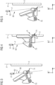
figures 3, 4 and 5 are larger-scale side-views of details of the apparatus according to the invention, during respective distinct operative conditions; -
figure 6 is a perspective view of a sealing member of the apparatus according to the present invention; -
figure 7 is a larger-scale perspective view, with parts removed for clarity, of a detail of the apparatus according to the invention; and -
figure 8 is a schematic side view, with parts removed for clarity, of a detail of the apparatus according to the invention. - With reference to
figure 1 ,number 1 indicates as a whole a packaging assembly for producing a plurality of sealed packages 2 containing a pourable product, preferably a pourable food product such as pasteurized or UHT milk, water, fruit juice, wine, peas, beans, etc. starting from atube 3 of packaging material. - In detail,
packaging assembly 1 is configured to formtube 3 starting from a web-like sheet 4 of packaging material, which is unwound off a reel 5 and fed along a forming path. - The
packaging assembly 1 is configured to form and seal a plurality ofpillow packs 2a containing the pourable product starting fromtube 3 and then to foldpillow packs 2a for obtaining the aforementioned formed, sealed and folded packages 2 containing the pourable product. - After being unwound off reel 5 and before being formed into
tube 3, sheet 4 of packaging material is sterilized, e.g. by applying a chemical sterilizing agent, such as hydrogen peroxide solution, which, once sterilization is completed, is removed from the surfaces of the packaging material, e.g. evaporated by heating. - Then,
packaging assembly 1 is configured to perform, sequentially, the following operations: - longitudinally folding sheet 4 of packaging material to obtain
tube 3 by means of folding means 6, known per se and not described in detail, and longitudinally sealingtube 3 to form a longitudinal sealing band; and - filling tube 3 (from above) with the pourable product.
- The
packaging assembly 1 comprises a forming and sealing apparatus configured for performing one or more of: - forming
tube 3 at successive portions thereof to impart (give) a predetermined external shape to such portions; - transversally sealing
tube 3 at equally spaced cross sections, so thatpillow packs 2a are obtained; - cutting
tube 3 at the above-mentioned cross sections to separatepillow packs 2a from one another; and - folding
pillow packs 2a to obtain fully folded packages 2. - As shown in the figures, the
packaging assembly 1 for forming and sealing the plurality of packages 2 comprises: - a longitudinal axis A along which the
tube 3 advances, that is an advancement direction of thetube 3 is parallel with respect to the longitudinal axis A; - a sealing device 7 configured for cyclically sealing the
tube 3 at successive cross-sections thereof and having a sealingmember 70 and acountersealing member 72 arranged at opposite sides of the longitudinal axis A; and - a
dispensing device 8 configured to provide afluid flow 80, e.g. a liquid flow, cyclically hitting (at least a portion of) thesealing member 70 during operation of thepackaging assembly 1. - The fluid flow 80, by hitting the sealing
member 70, may cyclically rinse at least a portion of the sealingmember 70. As considered herein, rinse comprises the act of cleansing by flushing with liquid (such as water), e.g. to remove corrosive elements on the sealingmember 70. - In particular, the
dispensing device 8 is a static (non-moving) component during operation of thepackaging assembly 1, i.e. thedispensing device 8 is a fixed component (e.g. to a support structure) of thepackaging assembly 1 during operation thereof. Thedispensing device 8 may be fixed with respect to the longitudinal axis A. This may be opposed to the sealingmember 70 andcountersealing member 72 which cyclically move with respect to the longitudinal axis A. - Similarly, the
fluid flow 80 may follow a stationary (unchanging) and/or constant flow direction F. That is, during operation, thefluid flow 80 is maintained along the (fixed) flow direction F. - Advantageously, the
fluid flow 80 may be directed to a certain region of thepackaging assembly 1 and the sealingmember 70 may pass through theflow 80 at predetermined moments of its cycle, see e.g.figures 3, 4 and 5 which exemplify part of a cycle of the sealingmember 70 according to the instant invention. - Advantageously, the flushing of the sealing
member 70 during operation may improve a lifetime of the sealingmember 70. - As previously anticipated, the sealing
member 70 and thecounter sealing member 72 are configured to cyclically move during operation of thepackaging assembly 1. - According to a known manner, the
tube 3 may advance along the longitudinal axis parallel to a first direction Z. The sealingmember 70 and thecountersealing member 72 are repeatedly movable towards and away from one another, e.g. along a second direction X orthogonal to the first direction Z, to cyclically cooperate with one another thereby clampingtube 3 in a jaw-like manner at said cross-sections forsealing tube 3 and defining transversal sealing bands which extend along a third direction Y orthogonal to both first direction Z and second direction X. - In particular, as shown in
figure 3 , thesealing member 70 and the countersealing member 72 (not shown in the figure) may move towards thetube 3. As shown infigure 4 , thesealing member 70 and the countersealing member 72 (not shown in the figure) may touch the tube at opposite sides of thereof. Finally, as shown infigure 5 , thesealing member 70 and the countersealing member 72 (not shown in the figure) may release thetube 3 and move away therefrom. -
Figure 6 exemplifies a sealingmember 70 that may be present in thepackaging assembly 1. The sealingmember 70 comprises asealing surface 74 configured to touch (or contact) an external surface of thetube 3 at a sealing region R. - In particular, the
fluid flow 80 may hit (rinse or flush) thesealing surface 74 before and/or after the sealingsurface 74 touches thetube 3. The sealingmember 70 may pass through thefluid flow 80 before or after the sealingmember 70 passes at the sealing region R. - Advantageously, the sealing
member 70, in particular the sealingsurface 74, may be rinsed or flushed before and/or after contact with thetube 3, thereby minimizing or eliminating any possible residual corrosive agents received from the external surface of thetube 3. - The sealing
member 70 may comprise arecess 76. In particular, thefluid flow 80 may hit (rinse or flush) therecess 76. - The
recess 76 may be configured to receive a cap (not shown) attached to thetube 3 and thefluid flow 80 may hit therecess 76 before therecess 76 receives the cap or after the cap leaves therecess 76. - Advantageously, the sealing
member 70, in particular therecess 76, may be rinsed or flushed before and/or after interacting with the cap, thereby minimizing or eliminating any possible residual corrosive agents received from the cap. - For example, during sterilization, the cap may be flushed with hydrogen peroxide. After the bath, on the external surface of the tube, where the cap is positioned, a minimal amount of hydrogen peroxide may remain that may fall on the sealing
member 70, and especially in therecess 76, during operation. Advantageously, by flushing therecess 76, any residual agent in therecess 76, that may be corrosive for the sealingmember 70, may be diluted or eliminated. - The
counter sealing member 72 may similarly comprise a counter sealing surface configured to touch (or contact) an external surface of thetube 3 at the sealing region R at the opposite side of thetube 3 with respect to the sealingsurface 74. - According to the instant invention, the
dispensing device 8 is configured to release a fluid, e.g. a liquid, preferably water. Thefluid flow 80 may cyclically flush the sealingmember 70. In other words, thefluid flow 80 may wash the sealingmember 70. - In particular, the provided fluid may comprise an anticorrosion fluid, preferably an anticorrosion liquid such as water. The anticorrosion fluid may be used to reduce or prevent corrosion of exposed surfaces of the sealing
member 70, such as the sealingsurface 74. - The provided fluid may thus comprise water, preferably cold water. Advantageously, the cold water may allow cooling down the sealing
member 70 in addition to avoiding a corrosion thereof. - The provided fluid may comprise process water. Advantageously, the use of process water may allow a reduction of water waste or a waste of similar products.
-
Figures 7 and8 illustrate further details of thedispensing device 8 according to one or more embodiments. - In particular, the
dispensing device 8 may be arranged on the same side of the sealingmember 70 with respect to the longitudinal axis A (and the tube 3). - The sealing
member 70 may be directly hit by thefluid flow 80. The fluid provided by the dispensingdevice 8 may fail to contact further surfaces before hitting the sealingmember 70. - Advantageously, this way the tube of packaging material may avoid being hit by the
fluid flow 80 and the sealingmember 70 may avoid being indirectly hit by thefluid flow 80 ricocheting from thetube 3. Accordingly, any possible residues that may be present on the packaging material forming thetube 3 may avoid being transported by thefluid flow 80 from thetube 3 towards the sealingmember 70. - As shown in
figure 7 , thedispensing device 8 may be positioned upstream of the sealing device 7 with respect to the advancing direction of thetube 3, e.g. parallel to the longitudinal axis A. In particular, thefluid flow 80 may be directed vertically and downwards. - The
dispensing device 8 may comprise anozzle 82 for spraying thefluid flow 80. An aperture of the nozzle may face the sealing device 7, in particular the sealingmember 70. - The
packaging assembly 1 may further comprise a component, positioned (immediately) upstream of the sealing device 7 with respect to the advancing direction of thetube 3 to which thedispensing device 8 may be fixed. The component may be static (i.e. non-moving) during operation of thepackaging assembly 1. - The component may comprise a support structure, e.g. a support ring, configured to support the advancing
tube 3 during advancement. -
Figure 8 shows an example of thedispensing device 8. Thedispensing device 8 may comprise aninlet pipe 84 configured to receive the fluid. Thedispensing device 8 may then be configured to redirect the fluid towards thenozzle 82 by means of asecond pipe 86 for dispensing thefluid flow 80. - The
dispensing device 8 may comprise further connectors 87 (only one connector visible in the figure) configured to provide a further fluid flow hitting (only) thetube 3, during operation of thepackaging assembly 1. The flow may be used to minimize friction between thetube 3 and the components of thepackaging assembly 1. Thefurther connectors 87 may receive the fluid from afurther pipe 88 receiving the fluid and may direct the fluid through a further nozzle (not shown in the figures). - In particular, the fluid exiting the
nozzle 82 and the further nozzle may be the same. Also, thefluid flow 80 and the further fluid flow may be synchronized. - As shown in the figures, the
fluid flow 80 may define a flat spray, in particular non-conic. Thefluid flow 80 may substantially extend in a (e.g. single) direction orthogonal to the longitudinal axis A, e.g. a direction parallel to the second axis Y. That is, thefluid flow 80 may resemble a lamina or a blade. In particular, theflow 80 may extend in the same direction as the sealingsurface 74. - Optionally, the
dispensing device 8 may be configured to hit (rinse or flush) at least an entire width of the sealingsurface 74, preferably at least an entire width of the sealingmember 70. - According to the instant invention, the
dispensing device 8 may be configured to continuously provide thefluid flow 80 during operation. That is, thefluid flow 80 may be a continuous flow. - The flow direction F of the
fluid flow 80 may be parallel with respect to the longitudinal axis A or the first direction Z as shown infig. 2 . Advantageously, this way it is possible to minimize a possibility of the tube being hit by thefluid flow 80. - The flow direction F may be oblique, i.e. not parallel nor perpendicular, with respect to the longitudinal axis A. The flow direction F may be inclined towards the
tube 3 and thefluid flow 80 may directly hit the sealingmember 70. - It will be appreciated that, even in case of an inclined flow, the sealing
member 70 may be hit by the fluid flow without the flow ricocheting from thetube 3. - Advantageously, this way it is possible to facilitate a flushing of the sealing
member 70, e.g. of the sealingsurface 74, after the sealing member passes through the sealing region R. - Generally, the
dispensing device 8 may be configured to maintain thefluid flow 80 at a distance from thetube 3. That is, thefluid flow 80 may be kept away from thetube 3. This way thefluid flow 80 may avoid collecting residual elements, corrosive for the sealingmember 70 and in particular for the sealingelement 74, from the external surface of thetube 3. - The
fluid flow 80 may hit (rinse or flush) the sealingmember 70 away from the sealing region R, e.g. away from thetube 3.
Claims (15)
- A packaging assembly (1) for forming and sealing a plurality of packages (2) containing a pourable product starting from a tube (3) of packaging material, the packaging assembly (1) comprising:- a longitudinal axis (A) along which the tube (3) advances;- a sealing device (7) configured for cyclically sealing the tube (3) at successive cross-sections thereof and having a sealing member (70) and a countersealing member (72) arranged at opposite sides of the longitudinal axis (A); and- a dispensing device (8) configured to provide a fluid flow (80) cyclically hitting the sealing member (70).
- The packaging assembly (1) according to claim 1, wherein the dispensing device (8) is a static component during operation of the packaging assembly (1).
- The packaging assembly (1) according to claim 1 or claim 2, wherein the dispensing device (8) is arranged on the same side of sealing member (70) with respect to the longitudinal axis (A).
- The packaging assembly (1) according to any of the previous claims, wherein the sealing member (70) is directly hit by the fluid flow (80).
- The packaging assembly (1) according to any of the previous claims, wherein the dispensing device (8) is positioned upstream of the sealing device (7) with respect to an advancing direction of the tube (3).
- The packaging assembly (1) according to any of the previous claims, comprising a component positioned upstream of the sealing device (7) with respect to an advancing direction of the tube (3), wherein the dispensing device (8) is fixed to said component.
- The packaging assembly (1) according to claim 6, wherein said component is a support structure configured to support the tube (3).
- The packaging assembly (1) according to any of the previous claims, wherein the provided fluid is an anticorrosion fluid, preferably an anticorrosion liquid such as water.
- The packaging assembly (1) according to any of the previous claims, wherein the sealing member (70) comprises a sealing surface (74) configured to cyclically touch the tube (3), wherein the fluid flow (80) hits said sealing surface (74) before and/or after the sealing surface (74) touches the tube (3).
- The packaging assembly (1) according to any of the previous claims, wherein the sealing member (70) comprises a recess (76), wherein the fluid flow (80) is further configured to flush the recess (76).
- The packaging assembly (1) according to any of the previous claims, wherein the fluid flow (80) defines a flat spray, preferably the fluid flow (80) extends in a direction (Y) orthogonal to the longitudinal axis, even more preferably the fluid flow (80) extends in a same direction as a sealing surface (74) of the sealing member (70).
- The packaging assembly (1) according to any of the previous claims, wherein the dispensing device (8) is configured to continuously provide the fluid flow (80).
- The packaging assembly (1) according to any of the previous claims, wherein a direction (F) of the fluid flow (80) is parallel with respect to the longitudinal axis (A) or a direction (F) of the fluid flow (80) is oblique with respect to the longitudinal axis (A).
- The packaging assembly (1) according to any of the previous claims, wherein the dispensing device (8) is configured to maintain the fluid flow (80) at a distance from the tube (3).
- The packaging assembly (1) according to any of the previous claims, wherein the fluid flow (80) hits the sealing member (70) away from a sealing region (R).
Applications Claiming Priority (1)
| Application Number | Priority Date | Filing Date | Title |
|---|---|---|---|
| IT102023000012438A IT202300012438A1 (en) | 2023-06-16 | 2023-06-16 | PACKAGING ASSEMBLY TO FORM AND SEAL A NUMBER OF PACKAGES CONTAINING A VERSABLE PRODUCT |
Publications (1)
| Publication Number | Publication Date |
|---|---|
| EP4477391A1 true EP4477391A1 (en) | 2024-12-18 |
Family
ID=87801631
Family Applications (1)
| Application Number | Title | Priority Date | Filing Date |
|---|---|---|---|
| EP24181370.8A Pending EP4477391A1 (en) | 2023-06-16 | 2024-06-11 | Packaging assembly for forming and sealing a plurality of packs containing a pourable product |
Country Status (4)
| Country | Link |
|---|---|
| EP (1) | EP4477391A1 (en) |
| CN (1) | CN120769796A (en) |
| IT (1) | IT202300012438A1 (en) |
| WO (1) | WO2024256380A1 (en) |
Citations (3)
| Publication number | Priority date | Publication date | Assignee | Title |
|---|---|---|---|---|
| US4129976A (en) * | 1976-09-30 | 1978-12-19 | Sig Schweizerische Industrie-Gesellschaft | Apparatus for forming, filling and closing bags |
| WO2007114752A1 (en) | 2006-03-31 | 2007-10-11 | Tetra Laval Holdings & Finance S.A. | Forming device, machine, packaging laminate web, forming method and process in producing packages |
| US10343800B2 (en) * | 2015-07-30 | 2019-07-09 | Toppan Printing Co., Ltd. | Ultrasonic sealing apparatus |
-
2023
- 2023-06-16 IT IT102023000012438A patent/IT202300012438A1/en unknown
-
2024
- 2024-06-11 WO PCT/EP2024/066059 patent/WO2024256380A1/en not_active Ceased
- 2024-06-11 EP EP24181370.8A patent/EP4477391A1/en active Pending
- 2024-06-11 CN CN202480014436.8A patent/CN120769796A/en active Pending
Patent Citations (3)
| Publication number | Priority date | Publication date | Assignee | Title |
|---|---|---|---|---|
| US4129976A (en) * | 1976-09-30 | 1978-12-19 | Sig Schweizerische Industrie-Gesellschaft | Apparatus for forming, filling and closing bags |
| WO2007114752A1 (en) | 2006-03-31 | 2007-10-11 | Tetra Laval Holdings & Finance S.A. | Forming device, machine, packaging laminate web, forming method and process in producing packages |
| US10343800B2 (en) * | 2015-07-30 | 2019-07-09 | Toppan Printing Co., Ltd. | Ultrasonic sealing apparatus |
Also Published As
| Publication number | Publication date |
|---|---|
| CN120769796A (en) | 2025-10-10 |
| IT202300012438A1 (en) | 2024-12-16 |
| WO2024256380A1 (en) | 2024-12-19 |
Similar Documents
| Publication | Publication Date | Title |
|---|---|---|
| RU2726545C1 (en) | Support for transverse sealing of tube from packing material and welding clamping jaws with support | |
| EP2284084B1 (en) | Folding unit for pourable food product packaging machines | |
| EP3053834B1 (en) | Forming assembly and method for forming a plurality of sealed packs for pourable food products starting from a tube of packaging material | |
| CN113710581B (en) | Packaging machine and method for producing sealed packages | |
| CN104781147B (en) | Folding unit for pourable food products packing machine | |
| RU2374153C2 (en) | Folding assembly of machine to pack fluid foodstuffs | |
| JP7787871B2 (en) | Package forming unit, packaging device having package forming unit, and package forming method | |
| RU2671154C2 (en) | Feeding unit for feeding sealed packs of pourable food products | |
| US7104028B2 (en) | Forming jaw for producing a succession of sealed packages from a tube of sheet packaging material | |
| RU2671468C2 (en) | Feeding node for feeding packages of liquid foodstuffs | |
| EP3009359B1 (en) | Feeding unit for feeding sealed packs of pourable food products | |
| WO2024256380A1 (en) | Packaging assembly for forming and sealing a plurality of packs containing a pourable product | |
| EP4197751A1 (en) | Packaging assembly for forming and sealing a plurality of packs containing a pourable product | |
| JP2024541816A (en) | Buffer unit for packaging device, packaging device, and method for manufacturing sealed package | |
| JP2001114222A (en) | Packaging unit for continuously producing sealed packages of injectable food products | |
| EP4289750A1 (en) | Forming device for a packaging assembly for forming and sealing a plurality of packages containing a pourable product and packaging assembly | |
| RU2588187C2 (en) | Packing machine and method of producing sealed packages for food products from packing material web | |
| WO2025185932A1 (en) | Nozzle unit, sterilizing agent removal assembly for a sterilization unit and packaging machine configured for the production of sealed packages containing a pourable product | |
| CN121469950A (en) | Kits for packaging machines and packaging machines for forming packages filled with pourable products. | |
| HK1086801A1 (en) | Packaging machine for producing sealed packages of pourable food products, and featuring an improved package fill device | |
| MXPA01002416A (en) | Method of producing sealed packages containing pourable food products from a tube of packing material, and packing unit implementing such a method | |
| HK1170990A (en) | Folding unit for pourable food product packaging machines |
Legal Events
| Date | Code | Title | Description |
|---|---|---|---|
| PUAI | Public reference made under article 153(3) epc to a published international application that has entered the european phase |
Free format text: ORIGINAL CODE: 0009012 |
|
| STAA | Information on the status of an ep patent application or granted ep patent |
Free format text: STATUS: THE APPLICATION HAS BEEN PUBLISHED |
|
| AK | Designated contracting states |
Kind code of ref document: A1 Designated state(s): AL AT BE BG CH CY CZ DE DK EE ES FI FR GB GR HR HU IE IS IT LI LT LU LV MC ME MK MT NL NO PL PT RO RS SE SI SK SM TR |
|
| STAA | Information on the status of an ep patent application or granted ep patent |
Free format text: STATUS: REQUEST FOR EXAMINATION WAS MADE |
|
| 17P | Request for examination filed |
Effective date: 20250618 |
|
| STAA | Information on the status of an ep patent application or granted ep patent |
Free format text: STATUS: EXAMINATION IS IN PROGRESS |
|
| 17Q | First examination report despatched |
Effective date: 20260331 |