EP4477301A1 - Stock mixing method and stock mixing system - Google Patents
Stock mixing method and stock mixing system Download PDFInfo
- Publication number
- EP4477301A1 EP4477301A1 EP24178128.5A EP24178128A EP4477301A1 EP 4477301 A1 EP4477301 A1 EP 4477301A1 EP 24178128 A EP24178128 A EP 24178128A EP 4477301 A1 EP4477301 A1 EP 4477301A1
- Authority
- EP
- European Patent Office
- Prior art keywords
- stock
- mixing
- scn
- components
- manifold
- Prior art date
- Legal status (The legal status is an assumption and is not a legal conclusion. Google has not performed a legal analysis and makes no representation as to the accuracy of the status listed.)
- Pending
Links
Images


Classifications
-
- D—TEXTILES; PAPER
- D21—PAPER-MAKING; PRODUCTION OF CELLULOSE
- D21B—FIBROUS RAW MATERIALS OR THEIR MECHANICAL TREATMENT
- D21B1/00—Fibrous raw materials or their mechanical treatment
- D21B1/04—Fibrous raw materials or their mechanical treatment by dividing raw materials into small particles, e.g. fibres
- D21B1/12—Fibrous raw materials or their mechanical treatment by dividing raw materials into small particles, e.g. fibres by wet methods, by the use of steam
- D21B1/30—Defibrating by other means
- D21B1/34—Kneading or mixing; Pulpers
- D21B1/342—Mixing apparatus
-
- D—TEXTILES; PAPER
- D21—PAPER-MAKING; PRODUCTION OF CELLULOSE
- D21C—PRODUCTION OF CELLULOSE BY REMOVING NON-CELLULOSE SUBSTANCES FROM CELLULOSE-CONTAINING MATERIALS; REGENERATION OF PULPING LIQUORS; APPARATUS THEREFOR
- D21C3/00—Pulping cellulose-containing materials
- D21C3/22—Other features of pulping processes
-
- B—PERFORMING OPERATIONS; TRANSPORTING
- B01—PHYSICAL OR CHEMICAL PROCESSES OR APPARATUS IN GENERAL
- B01F—MIXING, e.g. DISSOLVING, EMULSIFYING OR DISPERSING
- B01F23/00—Mixing according to the phases to be mixed, e.g. dispersing or emulsifying
- B01F23/50—Mixing liquids with solids
- B01F23/565—Mixing liquids with solids by introducing liquids in solid material, e.g. to obtain slurries
-
- B—PERFORMING OPERATIONS; TRANSPORTING
- B01—PHYSICAL OR CHEMICAL PROCESSES OR APPARATUS IN GENERAL
- B01F—MIXING, e.g. DISSOLVING, EMULSIFYING OR DISPERSING
- B01F23/00—Mixing according to the phases to be mixed, e.g. dispersing or emulsifying
- B01F23/50—Mixing liquids with solids
- B01F23/58—Mixing liquids with solids characterised by the nature of the liquid
- B01F23/581—Mixing liquids with solids, slurries or sludge, for obtaining a diluted slurry
-
- B—PERFORMING OPERATIONS; TRANSPORTING
- B01—PHYSICAL OR CHEMICAL PROCESSES OR APPARATUS IN GENERAL
- B01F—MIXING, e.g. DISSOLVING, EMULSIFYING OR DISPERSING
- B01F25/00—Flow mixers; Mixers for falling materials, e.g. solid particles
- B01F25/30—Injector mixers
- B01F25/31—Injector mixers in conduits or tubes through which the main component flows
- B01F25/311—Injector mixers in conduits or tubes through which the main component flows for mixing more than two components; Devices specially adapted for generating foam
-
- B—PERFORMING OPERATIONS; TRANSPORTING
- B01—PHYSICAL OR CHEMICAL PROCESSES OR APPARATUS IN GENERAL
- B01F—MIXING, e.g. DISSOLVING, EMULSIFYING OR DISPERSING
- B01F25/00—Flow mixers; Mixers for falling materials, e.g. solid particles
- B01F25/30—Injector mixers
- B01F25/31—Injector mixers in conduits or tubes through which the main component flows
- B01F25/314—Injector mixers in conduits or tubes through which the main component flows wherein additional components are introduced at the circumference of the conduit
- B01F25/3141—Injector mixers in conduits or tubes through which the main component flows wherein additional components are introduced at the circumference of the conduit with additional mixing means other than injector mixers
-
- B—PERFORMING OPERATIONS; TRANSPORTING
- B01—PHYSICAL OR CHEMICAL PROCESSES OR APPARATUS IN GENERAL
- B01F—MIXING, e.g. DISSOLVING, EMULSIFYING OR DISPERSING
- B01F25/00—Flow mixers; Mixers for falling materials, e.g. solid particles
- B01F25/40—Static mixers
-
- B—PERFORMING OPERATIONS; TRANSPORTING
- B01—PHYSICAL OR CHEMICAL PROCESSES OR APPARATUS IN GENERAL
- B01F—MIXING, e.g. DISSOLVING, EMULSIFYING OR DISPERSING
- B01F25/00—Flow mixers; Mixers for falling materials, e.g. solid particles
- B01F25/40—Static mixers
- B01F25/42—Static mixers in which the mixing is affected by moving the components jointly in changing directions, e.g. in tubes provided with baffles or obstructions
- B01F25/43—Mixing tubes, e.g. wherein the material is moved in a radial or partly reversed direction
- B01F25/431—Straight mixing tubes with baffles or obstructions that do not cause substantial pressure drop; Baffles therefor
- B01F25/4317—Profiled elements, e.g. profiled blades, bars, pillars, columns or chevrons
- B01F25/43172—Profiles, pillars, chevrons, i.e. long elements having a polygonal cross-section
-
- B—PERFORMING OPERATIONS; TRANSPORTING
- B01—PHYSICAL OR CHEMICAL PROCESSES OR APPARATUS IN GENERAL
- B01F—MIXING, e.g. DISSOLVING, EMULSIFYING OR DISPERSING
- B01F25/00—Flow mixers; Mixers for falling materials, e.g. solid particles
- B01F25/40—Static mixers
- B01F25/42—Static mixers in which the mixing is affected by moving the components jointly in changing directions, e.g. in tubes provided with baffles or obstructions
- B01F25/43—Mixing tubes, e.g. wherein the material is moved in a radial or partly reversed direction
- B01F25/431—Straight mixing tubes with baffles or obstructions that do not cause substantial pressure drop; Baffles therefor
- B01F25/43197—Straight mixing tubes with baffles or obstructions that do not cause substantial pressure drop; Baffles therefor characterised by the mounting of the baffles or obstructions
- B01F25/431971—Mounted on the wall
-
- B—PERFORMING OPERATIONS; TRANSPORTING
- B01—PHYSICAL OR CHEMICAL PROCESSES OR APPARATUS IN GENERAL
- B01F—MIXING, e.g. DISSOLVING, EMULSIFYING OR DISPERSING
- B01F33/00—Other mixers; Mixing plants; Combinations of mixers
- B01F33/80—Mixing plants; Combinations of mixers
-
- D—TEXTILES; PAPER
- D21—PAPER-MAKING; PRODUCTION OF CELLULOSE
- D21D—TREATMENT OF THE MATERIALS BEFORE PASSING TO THE PAPER-MAKING MACHINE
- D21D5/00—Purification of the pulp suspension by mechanical means; Apparatus therefor
- D21D5/28—Tanks for storing or agitating pulp
-
- D—TEXTILES; PAPER
- D21—PAPER-MAKING; PRODUCTION OF CELLULOSE
- D21F—PAPER-MAKING MACHINES; METHODS OF PRODUCING PAPER THEREON
- D21F1/00—Wet end of machines for making continuous webs of paper
- D21F1/08—Regulating consistency
-
- D—TEXTILES; PAPER
- D21—PAPER-MAKING; PRODUCTION OF CELLULOSE
- D21F—PAPER-MAKING MACHINES; METHODS OF PRODUCING PAPER THEREON
- D21F1/00—Wet end of machines for making continuous webs of paper
- D21F1/66—Pulp catching, de-watering, or recovering; Re-use of pulp-water
-
- B—PERFORMING OPERATIONS; TRANSPORTING
- B01—PHYSICAL OR CHEMICAL PROCESSES OR APPARATUS IN GENERAL
- B01F—MIXING, e.g. DISSOLVING, EMULSIFYING OR DISPERSING
- B01F2101/00—Mixing characterised by the nature of the mixed materials or by the application field
- B01F2101/47—Mixing of ingredients for making paper pulp, e.g. wood fibres or wood pulp
Definitions
- the present invention relates to stock mixing, especially in connection with pulp, textile and fiber web production. More especially the invention relates to a stock mixing method according to the preamble part of the independent method claim and to a stock mixing system according to the preamble part of the independent system claim.
- a typical production and treatment line comprises a forming section comprising a head box and a forming unit and a press section as well as a subsequent drying section and a reel-up.
- the fiber web production line can further comprise other devices and sections for finishing the fiber web, for example, a size press, a calender, a coating section, and typically at least one slitter-winder for forming customer rolls as well as a roll packaging apparatus.
- the fiber web production line is preceded by a system in which the fiber suspension, called stock, is prepared.
- stock a stock preparation system
- various stock components for example virgin and/or recycled pulp and/or broke are mixed together with dilution water, fillers and other desired additives are mixed with the stock and the stock or one or more of its components are, if considered necessary, de-aerated.
- the stock is fed into the fiber web production line via a mixing tank/-s and a machine tank/-s.
- the various component stocks included in the stock i.e.
- component stocks containing different kinds of fibers constitute the first raw material of the stock, i.e. the fibrous raw material of the stock.
- different fillers, additives or chemicals are added to the stock or the component stocks to improve the quality and printability of finished paper or the operability of the manufacturing process.
- the component stocks, fillers, additives and chemicals are stored in large storage tanks.
- the composition of the stock conveyed to the fiber web production line is adjusted in a dosing system at the stock preparation, where the different stock components included in the stock are blended with each other both in a pipe leading to the mixing tank and in the mixing tank itself, from where the stock is conveyed to the machine tank and from there further to the fiber web production line.
- the consistency of the stock to be fed into the paper machine is adjusted by changing the amount of dilution water fed into the stock, i.e. the adjustment of the consistency of the stock relates to the addition of dilution water to the stock in a suitable ratio to the amount and consistency of the stock.
- the mixing systems comprise separate mixing tanks and machine tanks in order to provide uniform and homogenous consistency of the stock.
- the mixing system comprises two tanks, two pumps, two mixers and piping system between the tanks. This makes the system rather complicated and cumbersome, as well as space and energy consuming. Additionally, the system has high carbon-dioxide discharges.
- patent application publication DE102008000256A1 is disclosed a system for diluting a fiber suspension in a dilution device and for adding several fluids via at least one feed device into the stream of the fiber suspension, in which at least one feed device is arranged before and at least one after a mixing device and the dilution device is arranged before the first feed device.
- a slurry mixing system comprising distribution ports, a static mixer, a dynamic mixer and a slurry tank, in which slurry is conveyed to a channel, which, in turn, passes through the static mixer and the dynamic mixer which, in turn, mixes the slurry conveyed by the plurality of slurry distribution ports to complete the mixed slurry into the slurry tank.
- EP2690216A1 is disclosed a system for producing a cellulose web or sheet from an aqueous suspension of cellulose fibers, comprising a mixing section for a slurry of cellulose fibers, a dilution section, wherein the slurry of cellulose fibers, coming from said mixing section, is diluted with water coming from the paper machine, to form the aqueous suspension of cellulose fibers,
- the mixing section for the slurry of cellulose fibers comprises a mixer with a vertically extending tubular body, which tubular body is in fluid connection with a machine tank below, equipped with a mechanical mixer; and the machine tank is in fluid connection with said dilution section, in which between said machine tank and the dilution section no further intermediate tanks are present and the mixer is connected to the machine tank below through a curved connection pipe.
- An object of the invention is to create a stock mixing method and system, in which the disadvantages and problems of prior art are eliminated or at least minimized.
- an object of the invention is to create an improved stock mixing method and system, in particular in respect of space and energy requirements.
- the stock mixing method according to the invention is mainly characterized by the features of the characterizing part of the independent method claim.
- the stock mixing system according to the invention is mainly characterized by the features of the characterizing part of the independent system claim.
- a stock is mixed of dilution water and of at least two stock components and the stock mixing method is performed in a stock mixing system, whereby in the method the stock components are mixed in an assembly of a mixing manifold for premixing of the stock components and a static mixer, which assembly is part of the stock mixing system, the stock components are fed to the mixing manifold and the dilution water is fed to the mixing manifold at the latest as a second last addition and at least one stock component is fed as last addition to the stock mixture of the stock components in the mixing manifold.
- the stock mixture of the stock components and the dilution water is mixed in the static mixer.
- the method components comprise stock components, which stock components SC1, SC2, SC3, SCN can be non-synthetic and/or synthetic fiber-based stock.
- the consistencies and amounts of the stock components can vary.
- the stock components may comprise water and/or chemicals and/or natural fibers and/or synthetic fibers and/or fillers.
- the stock components are added in consistency up to 5%.
- the stock mixing system comprises at least one pipe line for dilution water and at least two pipe lines for stock components to be mixed, wherein the stock mixing system comprises an assembly of a mixing manifold and a static mixer for mixing the dilution water and the stock components, and only one tank for the stock of the mixed the dilution water and the stock components located in flow direction after the static mixer, wherein the pipe lines for the dilution water and the stock components are connected to feed branches of the mixing manifold and in the flow direction after the feed branch for the dilution water at least one feed branch for at least one stock component of the stock components is located.
- the only one tank is a mixing or machine tank.
- the static mixer is connected by at least one straight or curved outlet pipe to the machine tank.
- degree of curvature of the curved outlet pipe is 0-180 decrees, advantageously 0-90 degrees.
- the mixing manifold has substantially a conical shape.
- shape of the mixing manifold flow dynamics in the mixing manifold are optimized such, that preferably an accelerating flow is provided.
- the mixing manifold comprises pipe parts and at least one cone pipe part.
- diameter of the pipe parts increases in flow direction of the mixing manifold such, that a pipe part upstream in the flow direction of the mixing manifold has a smaller diameter than a pipe part downstream in the flow direction of the mixing manifold. This provides that velocity of the flow remains at desired level during the flow or the stock through the mixing manifold.
- coning angle of the cone pipe parts is constant in flow direction of the mixing manifold and length of the cone pipe parts varies in flow direction of the mixing manifold.
- coning angle of the cone pipe parts increases in flow direction of the mixing manifold and length of the cone pipe parts is constant in flow direction of the mixing manifold.
- the static mixer comprises streamlined wedges attached to the inner surface of the static mixer.
- the mixing system comprises an assembly of a mixing manifold and a static mixer.
- the mixing system comprises only one tank.
- the tank is a mixing or machine tank.
- a homogenous and uniform stock is achieved by premixing the stock components in the mixing manifold and by following mixing treatment in the static mixer. This also provides for suitable stock for consistency measurement, as the stock is very even, and no significant consistency variations occur after the stock components have been passed through the assembly of the mixing manifold and the static mixer.
- the dimensioning of the mixing manifold is configured to provide velocity ration over 1 after a stock component addition.
- the dimensioning of the mixing manifold is configured to provide velocity of the flow in the range of 0,5 - 4 m/s such, that turbulence of the stock flow is at desired level in view of consistency measurement requirements.
- the system and the method according to the invention is applicable in mixing of textile fiber stocks.
- the mixing system according to the invention requires less tanks, less pumps and related equipment, less pipes and related instrumentation, thus, less space is needed and less energy is needed as well as the carbon-dioxide discharges are decreased. Additionally, a uniform, even and homogenous stock is mixed of stock components and dilution water.
- the invention also provides, that reliable consistency measurement of the stock flow at a desired location in connection with the mixing or machine tank as good, turbulent flow of the stock is provided by the assembly of the mixing manifold and the static mixer.
- FIG 1 is schematically shown an example of a stock mixing system 100.
- the mixing system 100 comprises pipelines LD, L1, L2, L3, LN: more than one pipelines L1, L2, L3, LN to guide stock components SC1, SC2, SC3, SCN to be mixed and at least one pipeline LD to guide dilution water DW to adjust the consistency of stock S formed of the mixed stock components SC1, SC2, SC3, SCN and dilution water DW.
- the mixing system 100 comprises a mixing manifold 10, to which the dilution water DW via the pipeline LD and the stock components SC1, SC2, SC3, SCN via the pipelines L1, L2, L3, LN are guided for premixing and for adjusting the consistency of the stock S.
- the dilution water DW is provided by the pipeline LD to the mixing manifold 10 at a location before at least one location of providing a stock component SCN.
- last component to be provided to the mixing manifold is not dilution water DW but a stock component SCN.
- the mixing manifold 10 is formed as an assembly with a static mixer for mixing of the stock S.
- the mixed stock S is guide via a pipeline L40 to a mixing or machine tank 50 for finalizing and storing the stock S to be guided further through a pipeline L50 via further systems for treating the stock towards a head box of a fiber web production line for producing a fiber web.
- the mixing system 100 comprises only one mixing or machine tank 50.
- Flow direction in the pipelines LD, L1, L2, L3, LN, L40, L50 is indicated by an arrow sign in connection with the pipeline LD, L1, L2, L3, LN, L40, L50.
- stock components SC1, SC2, SC3, SCN for the stock S are selected and dosed to the mixing manifold 10 to be premixed.
- the amount of dilution water DW is dosed to the mixing manifold.
- the stock components SC1, SC2, SC3, SCN can be non-synthetic and/or synthetic fiber-based stock.
- the consistencies and amounts of the stock components SC1, SC2, SC3, SCN can vary.
- the stock components may comprise water and/or chemicals and/or natural fibers and/or synthetic fibers and/or fillers.
- the stock components are advantageously added in consistency up to 5%. The consistency of the stock component mixture is adjusted by the addition of the dilution water DW.
- the dilution water DW is added to the stock component mixture in the mixing manifold 10 at the latest as second last addition and thus, the last addition to the mixing manifold 10 is a stock component.
- the stock components SC1, SC2, SC3, SCN are premixed in the mixing manifold 10 and thereafter fed to the static mixer 40 for mixing and then the consistency of the stock component mixture is determined, advantageously by measurement.
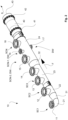
- FIG 2 is schematically shown an example of a stock mixing manifold 10 and static mixer 40 assembly of a mixing system 100.
- the mixing manifold 10 is connectable to eight pipelines for providing stock components SC1, SC2, SC3, SCN-1, SCN and dilution water DW to form stock S.
- the mixing manifold 10 comprises feed branches 11, 12, 13, 14, 15, 16, 17, 18 connectable to the pipelines for providing stock components SC1, SC2, SC3, SCN-1, SCN and dilution water DW.
- the dilution water DW is provided by the pipeline to the mixing manifold 10 at a location before at least one location of providing a stock component SCN-1, SCN i.e. advantageously via the second last or the third last feed branch 16, 17.
- last component to be provided to the mixing manifold is not dilution water DW but a stock component SCN provided via the last feed branch 18.
- the feed branches 11, 12, 13, 14, 15, 16, 17, 18 can be located around main circumference of the mixing manifold 10 at desired angular positions, i.e. not only as shown in the example of the figure 2 mainly same angular position. At least two of the feed branches 11, 12, 13, 14, 15, 16, 17, 18 can also be located at same length position but at different angular position.
- the mixing manifold 10 comprises pipe parts 21, 22, 23, 24 and cone pipe part 31, 32.
- the pipe parts 21, 22, 23, 24 are substantially cylindrical i.e. along length of a pipe part the diameter is same.
- the cone pipe parts 31, 32 are conical in flow direction F of stock components in the mixing manifold i.e. have an increasing diameter along length of a cone pipe part.
- the mixing manifold 10 can be constructed of releasable pipe and/or cone pipe parts attached to each other.
- the mixing manifold 10 has in flow direction F of the stock components in the mixing manifold 10 increasing diameter to control velocity of the flow of the stock components in the mixing manifold 10.
- the diameter of pipe parts 21, 22, 23, 24 and conicalness of the cone pipe parts 31, 32 is selected such, that the flow velocity in the mixing manifold 10 is in range of 0,5-4 m/s.
- the static mixer 40 is connected to the mixing manifold 10 with a flange connection 41.
- the static mixer 40 is also connected with another flange connection 42 to an outlet pipe 43, which leads the stock to outlet end of the mixing manifold 10 is to the mixing or machine tank 50 ( fig. 1 ).
- FIG 3 is schematically shown another example of a stock mixing manifold 10 and static mixer 40 assembly of a mixing system 100.
- the mixing manifold 10 is connectable to eight pipelines for providing stock components SC1, SC2, SC3, SCN and dilution water DW to form stock S.
- the mixing manifold 10 comprises feed branches 11, 12, 13, 14, 15, 16, 17 connectable to the pipelines for providing stock components SC1, SC2, SC3, SCN and dilution water DW.
- the dilution water DW is provided by the pipeline to the mixing manifold 10 at a location before at least one location of providing a stock component SCN i.e. advantageously via the second last feed branch 16.
- last component to be provided to the mixing manifold is not dilution water DW but a stock component SCN provided via the last feed branch 17.
- the feed branches 11, 12, 13, 14, 15, 16, 17 can be located around main circumference of the mixing manifold 10 at desired angular positions, i.e. not only as shown in the example of the figure 2 mainly same angular position. At least two of the feed branches 11, 12, 13, 14, 15, 16, 17 can also be located at same length position but at different angular position.
- the mixing manifold 10 comprises pipe parts 21, 22, 23, 24 and cone pipe part 31, 32.
- the pipe parts 21, 22, 23, 24 are substantially cylindrical i.e. along length of a pipe part the diameter is same.
- the cone pipe parts 31, 32 are conical in flow direction F of stock components in the mixing manifold i.e. have an increasing diameter along length of a cone pipe part.
- the mixing manifold 10 can be constructed of releasable pipe and/or cone pipe parts attached to each other.
- the mixing manifold 10 has in flow direction F of the stock components in the mixing manifold 10 increasing diameter to control velocity of the flow of the stock components in the mixing manifold 10.
- the diameter of pipe parts 21, 22, 23, 24 and conicalness of the cone pipe parts 31, 32 is selected such, that the flow velocity in the mixing manifold 10 is 0,5-4 m/s.
- the static mixer 40 is connected to the mixing manifold 10 with a flange connection 41.
- the static mixer 40 is also connected with another flange connection 42 to a curved outlet pipe 44 for providing increased uniformity of the stock S.
- the curved outlet pipe 44 is attached to an outlet pipe 43, which leads the stock to outlet end of the mixing manifold 10 is to the mixing or machine tank 50 ( fig. 1 ).
- the pipe parts 21, 22, 23, 24 and the cone pipe parts 31, 32 may have same or different imaginary center axis.
- the curved form of the curved outlet pipe 44 further improves the mixing of the stock S.
- the configuration of the assembly of the mixing manifold 10 and the static mixer 40 provide turbulent flow of the stock components SC1, SC2, SC3, SCN-1, SCN and the dilution water DW in the mixing manifold 10 improving the uniformness and evenness of the stock mixture of the stock components SC1, SC2, SC3, SCN-1, SCN and the dilution water DW and the following mixing treatment in the static mixer 40 further improves the uniformity and evenness of the stock S.
- very good stock S is achieved for further treatment and especially suitable in respect of consistency measurement properties of the stock S.
- the form of the mixing manifold 10 is substantially conical.
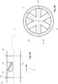
- Figs 4A-4B is schematically shown an example of a static mixer 40 provided with flange connections 41; 42 for attachment of the static mixer 40 to inlet and outlet pipes.
- the static mixer 40 comprises streamlined wedges of the static mixer 45 attached to the inner surface of the static mixer 40 and are axially located over at least partially over the length of the static mixer 40.
- the static mixer 40 comprises at least three wedges, advantageously at least six wedges.
- the streamlined wedges 45 are substantially triangular, peak of the triangular form pointing towards the center C of the static mixer 40.
- the flow direction F in the static mixer 40 is indicated by an arrow in figure 4A .
Landscapes
- Chemical & Material Sciences (AREA)
- Chemical Kinetics & Catalysis (AREA)
- Dispersion Chemistry (AREA)
- Engineering & Computer Science (AREA)
- Mechanical Engineering (AREA)
- Life Sciences & Earth Sciences (AREA)
- Wood Science & Technology (AREA)
Abstract
The invention relates to a stock mixing method, in which stock mixing method a stock (S) is mixed of dilution water (DW) and of at least two stock components (SC1, SC2, SC3, SCN-1, SCN) and which stock mixing method is performed in a stock mixing system (100). In the method the stock components (SC1, SC2, SC3, SCN-1, SCN) are mixed in an assembly of a mixing manifold (10) and a static mixer (40), which assembly is part of the stock mixing system (100). The stock components (SC1, SC2, SC3, SCN-1, SCN) are fed to the mixing manifold (10), that the dilution water (DW) is fed to the mixing manifold (10) at the latest as a second last addition and at least one stock component (SCN) is fed as last addition to the stock mixture of the stock components (SC1, SC2, SC3, SCN-1) in the mixing manifold (10). The invention also relates to a stock mixing system (100).
Description
- The present invention relates to stock mixing, especially in connection with pulp, textile and fiber web production. More especially the invention relates to a stock mixing method according to the preamble part of the independent method claim and to a stock mixing system according to the preamble part of the independent system claim.
- As known from the prior art in fiber web production lines, especially in paper and board production lines, the fiber web is produced and treated in an assembly formed by a number of apparatuses arranged consecutively in a process line. A typical production and treatment line comprises a forming section comprising a head box and a forming unit and a press section as well as a subsequent drying section and a reel-up. The fiber web production line can further comprise other devices and sections for finishing the fiber web, for example, a size press, a calender, a coating section, and typically at least one slitter-winder for forming customer rolls as well as a roll packaging apparatus.
- Before the head box stock formed of fiber suspension comprising fibers are treated to be fed into the head box and to be used to produce the fiber webs in a fiber web production line. Thus, the fiber web production line is preceded by a system in which the fiber suspension, called stock, is prepared. At this system, a stock preparation system, various stock components, for example virgin and/or recycled pulp and/or broke are mixed together with dilution water, fillers and other desired additives are mixed with the stock and the stock or one or more of its components are, if considered necessary, de-aerated. The stock is fed into the fiber web production line via a mixing tank/-s and a machine tank/-s. The various component stocks included in the stock, i.e. component stocks containing different kinds of fibers, constitute the first raw material of the stock, i.e. the fibrous raw material of the stock. Also, different fillers, additives or chemicals are added to the stock or the component stocks to improve the quality and printability of finished paper or the operability of the manufacturing process. Typically, the component stocks, fillers, additives and chemicals are stored in large storage tanks. The composition of the stock conveyed to the fiber web production line is adjusted in a dosing system at the stock preparation, where the different stock components included in the stock are blended with each other both in a pipe leading to the mixing tank and in the mixing tank itself, from where the stock is conveyed to the machine tank and from there further to the fiber web production line. The consistency of the stock to be fed into the paper machine is adjusted by changing the amount of dilution water fed into the stock, i.e. the adjustment of the consistency of the stock relates to the addition of dilution water to the stock in a suitable ratio to the amount and consistency of the stock.
- It is known from prior art that different types of stock mixing systems are used to mix different stock components and dilution water in the stock preparation system. The mixing systems comprise separate mixing tanks and machine tanks in order to provide uniform and homogenous consistency of the stock. Typically the mixing system comprises two tanks, two pumps, two mixers and piping system between the tanks. This makes the system rather complicated and cumbersome, as well as space and energy consuming. Additionally, the system has high carbon-dioxide discharges.
- In patent application publication
DE102008000256A1 is disclosed a system for diluting a fiber suspension in a dilution device and for adding several fluids via at least one feed device into the stream of the fiber suspension, in which at least one feed device is arranged before and at least one after a mixing device and the dilution device is arranged before the first feed device. - In patent application publication
US2005269051A1 is disclosed an apparatus for blending diverse liquid flows in a paper making machine, comprising a mixing pipe into which the diverse flows are discharged, and a degassing rotor situated in the mixing pipe, in which there is at least three feed pipes carrying a respective three diverse liquid flows, discharge into said mixing pipe and one of the feed pipes discharges dilution water into the mixing pipe and at least two of the feed pipes discharge a respective two pulp components into the mixing pipe. - In utility model publication
CN206661107U is disclosed a slurry mixing system comprising distribution ports, a static mixer, a dynamic mixer and a slurry tank, in which slurry is conveyed to a channel, which, in turn, passes through the static mixer and the dynamic mixer which, in turn, mixes the slurry conveyed by the plurality of slurry distribution ports to complete the mixed slurry into the slurry tank. - In patent application publication
EP2690216A1 is disclosed a system for producing a cellulose web or sheet from an aqueous suspension of cellulose fibers, comprising a mixing section for a slurry of cellulose fibers, a dilution section, wherein the slurry of cellulose fibers, coming from said mixing section, is diluted with water coming from the paper machine, to form the aqueous suspension of cellulose fibers, in which the mixing section for the slurry of cellulose fibers comprises a mixer with a vertically extending tubular body, which tubular body is in fluid connection with a machine tank below, equipped with a mechanical mixer; and the machine tank is in fluid connection with said dilution section, in which between said machine tank and the dilution section no further intermediate tanks are present and the mixer is connected to the machine tank below through a curved connection pipe. - An object of the invention is to create a stock mixing method and system, in which the disadvantages and problems of prior art are eliminated or at least minimized.
- In particular an object of the invention is to create an improved stock mixing method and system, in particular in respect of space and energy requirements.
- In order to achieve the above objects and those that will come apparent later the stock mixing method according to the invention is mainly characterized by the features of the characterizing part of the independent method claim. The stock mixing system according to the invention, in turn, is mainly characterized by the features of the characterizing part of the independent system claim. Advantageous aspects and features of the invention are presented in the dependent claims.
- According to the invention in the stock mixing method a stock is mixed of dilution water and of at least two stock components and the stock mixing method is performed in a stock mixing system, whereby in the method the stock components are mixed in an assembly of a mixing manifold for premixing of the stock components and a static mixer, which assembly is part of the stock mixing system, the stock components are fed to the mixing manifold and the dilution water is fed to the mixing manifold at the latest as a second last addition and at least one stock component is fed as last addition to the stock mixture of the stock components in the mixing manifold.
- According to the invention in the method after premixing the stock components and the dilution water in the mixing manifold, the stock mixture of the stock components and the dilution water is mixed in the static mixer.
- According to an advantageous feature of the invention in the method components comprise stock components, which stock components SC1, SC2, SC3, SCN can be non-synthetic and/or synthetic fiber-based stock. The consistencies and amounts of the stock components can vary. The stock components may comprise water and/or chemicals and/or natural fibers and/or synthetic fibers and/or fillers.
- According to an advantageous feature of the invention the stock components are added in consistency up to 5%.
- According to the invention the stock mixing system comprises at least one pipe line for dilution water and at least two pipe lines for stock components to be mixed, wherein the stock mixing system comprises an assembly of a mixing manifold and a static mixer for mixing the dilution water and the stock components, and only one tank for the stock of the mixed the dilution water and the stock components located in flow direction after the static mixer, wherein the pipe lines for the dilution water and the stock components are connected to feed branches of the mixing manifold and in the flow direction after the feed branch for the dilution water at least one feed branch for at least one stock component of the stock components is located. Advantageously, the only one tank is a mixing or machine tank.
- According to an advantageous feature of the invention the static mixer is connected by at least one straight or curved outlet pipe to the machine tank.
- According to an advantageous feature of the invention degree of curvature of the curved outlet pipe is 0-180 decrees, advantageously 0-90 degrees.
- According to an advantageous feature of the invention the mixing manifold has substantially a conical shape. By the shape of the mixing manifold flow dynamics in the mixing manifold are optimized such, that preferably an accelerating flow is provided.
- According to an advantageous feature of the invention the mixing manifold comprises pipe parts and at least one cone pipe part.
- According to an advantageous feature of the invention diameter of the pipe parts increases in flow direction of the mixing manifold such, that a pipe part upstream in the flow direction of the mixing manifold has a smaller diameter than a pipe part downstream in the flow direction of the mixing manifold. This provides that velocity of the flow remains at desired level during the flow or the stock through the mixing manifold.
- According to an advantageous feature of the invention coning angle of the cone pipe parts is constant in flow direction of the mixing manifold and length of the cone pipe parts varies in flow direction of the mixing manifold.
- According to an advantageous feature of the invention coning angle of the cone pipe parts increases in flow direction of the mixing manifold and length of the cone pipe parts is constant in flow direction of the mixing manifold.
- According to an advantageous feature of the invention the static mixer comprises streamlined wedges attached to the inner surface of the static mixer.
- According to an advantageous aspect of the invention the mixing system comprises an assembly of a mixing manifold and a static mixer. The mixing system comprises only one tank. Advantageously, the tank is a mixing or machine tank. Thus, improved space and energy requirements are achieved compared to prior art systems as several tanks are no more needed. Additionally, a homogenous and uniform stock is achieved by premixing the stock components in the mixing manifold and by following mixing treatment in the static mixer. This also provides for suitable stock for consistency measurement, as the stock is very even, and no significant consistency variations occur after the stock components have been passed through the assembly of the mixing manifold and the static mixer.
- According to an advantageous aspect of the invention the dimensioning of the mixing manifold is configured to provide velocity ration over 1 after a stock component addition.
- According to an advantageous aspect of the invention the dimensioning of the mixing manifold is configured to provide velocity of the flow in the range of 0,5 - 4 m/s such, that turbulence of the stock flow is at desired level in view of consistency measurement requirements.
- In addition to methods and systems relating to stock mixing in connection with fiber web production, such as paper and board webs, the system and the method according to the invention is applicable in mixing of textile fiber stocks.
- By the invention and its advantageous features several advantages are achieved: Compared to stock mixing systems known from prior art for providing a stock with corresponding properties the mixing system according to the invention requires less tanks, less pumps and related equipment, less pipes and related instrumentation, thus, less space is needed and less energy is needed as well as the carbon-dioxide discharges are decreased. Additionally, a uniform, even and homogenous stock is mixed of stock components and dilution water. The invention also provides, that reliable consistency measurement of the stock flow at a desired location in connection with the mixing or machine tank as good, turbulent flow of the stock is provided by the assembly of the mixing manifold and the static mixer.
- Aspects of the invention, however, together with additional objects and advantages thereof, will be best understood from the following description of some example embodiments when read in connection with the accompanying drawings and in the following the invention is described in more detail referring to the accompanying drawing, in which
- In
figure 1 is schematically shown an advantageous example of a stock mixing system according to the invention. - In
figure 2 is schematically shown an advantageous example of a stock mixing manifold and static mixer assembly according to the invention. - In
figure 3 is schematically shown another advantageous example of a stock mixing manifold and static mixer assembly according to the invention. - In
figures 4A-4B is schematically shown an advantageous example of a static mixer. - During the course of this description like numbers and signs will be used to identify like elements according to the different views which illustrate the invention. Repetition of some reference signs may have been omitted in the figures for clarity reasons.
- In
figure 1 is schematically shown an example of astock mixing system 100. Themixing system 100 comprises pipelines LD, L1, L2, L3, LN: more than one pipelines L1, L2, L3, LN to guide stock components SC1, SC2, SC3, SCN to be mixed and at least one pipeline LD to guide dilution water DW to adjust the consistency of stock S formed of the mixed stock components SC1, SC2, SC3, SCN and dilution water DW. Themixing system 100 comprises a mixingmanifold 10, to which the dilution water DW via the pipeline LD and the stock components SC1, SC2, SC3, SCN via the pipelines L1, L2, L3, LN are guided for premixing and for adjusting the consistency of the stock S. The dilution water DW is provided by the pipeline LD to the mixingmanifold 10 at a location before at least one location of providing a stock component SCN. Thus, last component to be provided to the mixing manifold is not dilution water DW but a stock component SCN. The mixingmanifold 10 is formed as an assembly with a static mixer for mixing of the stock S. The mixed stock S is guide via a pipeline L40 to a mixing ormachine tank 50 for finalizing and storing the stock S to be guided further through a pipeline L50 via further systems for treating the stock towards a head box of a fiber web production line for producing a fiber web. Themixing system 100 comprises only one mixing ormachine tank 50. Flow direction in the pipelines LD, L1, L2, L3, LN, L40, L50 is indicated by an arrow sign in connection with the pipeline LD, L1, L2, L3, LN, L40, L50. - In stock mixing method stock components SC1, SC2, SC3, SCN for the stock S are selected and dosed to the mixing
manifold 10 to be premixed. In the method the amount of dilution water DW is dosed to the mixing manifold. The stock components SC1, SC2, SC3, SCN can be non-synthetic and/or synthetic fiber-based stock. The consistencies and amounts of the stock components SC1, SC2, SC3, SCN can vary. The stock components may comprise water and/or chemicals and/or natural fibers and/or synthetic fibers and/or fillers. The stock components are advantageously added in consistency up to 5%. The consistency of the stock component mixture is adjusted by the addition of the dilution water DW. In the stock mixing method the dilution water DW is added to the stock component mixture in the mixingmanifold 10 at the latest as second last addition and thus, the last addition to the mixingmanifold 10 is a stock component. The stock components SC1, SC2, SC3, SCN are premixed in the mixingmanifold 10 and thereafter fed to thestatic mixer 40 for mixing and then the consistency of the stock component mixture is determined, advantageously by measurement. - In
figure 2 is schematically shown an example of astock mixing manifold 10 andstatic mixer 40 assembly of amixing system 100. In this example the mixingmanifold 10 is connectable to eight pipelines for providing stock components SC1, SC2, SC3, SCN-1, SCN and dilution water DW to form stock S. The mixingmanifold 10 comprisesfeed branches manifold 10 at a location before at least one location of providing a stock component SCN-1, SCN i.e. advantageously via the second last or the thirdlast feed branch last feed branch 18. Thefeed branches manifold 10 at desired angular positions, i.e. not only as shown in the example of thefigure 2 mainly same angular position. At least two of thefeed branches manifold 10 comprisespipe parts cone pipe part pipe parts cone pipe parts manifold 10 can be constructed of releasable pipe and/or cone pipe parts attached to each other. The mixingmanifold 10 has in flow direction F of the stock components in the mixingmanifold 10 increasing diameter to control velocity of the flow of the stock components in the mixingmanifold 10. The diameter ofpipe parts cone pipe parts manifold 10 is in range of 0,5-4 m/s. To form the assembly of the mixingmanifold 10 and thestatic mixer 40, thestatic mixer 40 is connected to the mixingmanifold 10 with aflange connection 41. Thestatic mixer 40 is also connected with anotherflange connection 42 to anoutlet pipe 43, which leads the stock to outlet end of the mixingmanifold 10 is to the mixing or machine tank 50 (fig. 1 ). - In
figure 3 is schematically shown another example of astock mixing manifold 10 andstatic mixer 40 assembly of amixing system 100. In this example the mixingmanifold 10 is connectable to eight pipelines for providing stock components SC1, SC2, SC3, SCN and dilution water DW to form stock S. The mixingmanifold 10 comprisesfeed branches manifold 10 at a location before at least one location of providing a stock component SCN i.e. advantageously via the secondlast feed branch 16. Thus, last component to be provided to the mixing manifold is not dilution water DW but a stock component SCN provided via thelast feed branch 17. Thefeed branches manifold 10 at desired angular positions, i.e. not only as shown in the example of thefigure 2 mainly same angular position. At least two of thefeed branches manifold 10 comprisespipe parts cone pipe part pipe parts cone pipe parts manifold 10 can be constructed of releasable pipe and/or cone pipe parts attached to each other. The mixingmanifold 10 has in flow direction F of the stock components in the mixingmanifold 10 increasing diameter to control velocity of the flow of the stock components in the mixingmanifold 10. The diameter ofpipe parts cone pipe parts manifold 10 is 0,5-4 m/s. To form the assembly of the mixingmanifold 10 and thestatic mixer 40, thestatic mixer 40 is connected to the mixingmanifold 10 with aflange connection 41. Thestatic mixer 40 is also connected with anotherflange connection 42 to acurved outlet pipe 44 for providing increased uniformity of the stock S. Thecurved outlet pipe 44 is attached to anoutlet pipe 43, which leads the stock to outlet end of the mixingmanifold 10 is to the mixing or machine tank 50 (fig. 1 ). Thepipe parts cone pipe parts curved outlet pipe 44 further improves the mixing of the stock S. - The configuration of the assembly of the mixing
manifold 10 and thestatic mixer 40 provide turbulent flow of the stock components SC1, SC2, SC3, SCN-1, SCN and the dilution water DW in the mixingmanifold 10 improving the uniformness and evenness of the stock mixture of the stock components SC1, SC2, SC3, SCN-1, SCN and the dilution water DW and the following mixing treatment in thestatic mixer 40 further improves the uniformity and evenness of the stock S. Thus very good stock S is achieved for further treatment and especially suitable in respect of consistency measurement properties of the stock S. - Advantageously, the form of the mixing
manifold 10 is substantially conical. -
Figs 4A-4B is schematically shown an example of astatic mixer 40 provided withflange connections 41; 42 for attachment of thestatic mixer 40 to inlet and outlet pipes. Thestatic mixer 40 comprises streamlined wedges of thestatic mixer 45 attached to the inner surface of thestatic mixer 40 and are axially located over at least partially over the length of thestatic mixer 40. Thestatic mixer 40 comprises at least three wedges, advantageously at least six wedges. Thestreamlined wedges 45 are substantially triangular, peak of the triangular form pointing towards the center C of thestatic mixer 40. The flow direction F in thestatic mixer 40 is indicated by an arrow infigure 4A . - In the description in the foregoing, although some functions have been described with reference to certain features, those functions may be performable by other features whether described or not. Although features have been described with reference to certain embodiments or examples, those features may also be present in other embodiments or examples whether described or not. Above the invention has been described by referring to some advantageous examples only to which the invention is not to be narrowly limited. Many modifications and alterations are possible within the invention as defined in the following claims.
- Reference signs used in the drawing:
- 10 mixing manifold
- 11, 12, 13, 14, 15, 16, 17, 18 feed branch
- 21, 22, 23, 24 pipe part
- 31, 32 cone pipe part
- 40 static mixer
- 41, 42 flange connection
- 43, 44 outlet pipe
- 45 streamlined wedges
- 50 mixing or machine tank
- 100 mixing system
- C center
- DW dilution water
- F flow direction
- LD, L1, L2, L3, LN, L40, L50 pipeline
- S stock
- SC1, SC2, SC3, SCN-1, SCN stock component
Claims (10)
- Stock mixing method, in which stock mixing method a stock (S) is mixed of dilution water (DW) and of at least two stock components (SC1, SC2, SC3, SCN-1, SCN) and which stock mixing method is performed in a stock mixing system (100), in which method the stock components (SC1, SC2, SC3, SCN-1, SCN) are mixed in an assembly of a mixing manifold (10) and a static mixer (40), which assembly is part of the stock mixing system (100), in which stock components (SC1, SC2, SC3, SCN-1, SCN) are fed to the mixing manifold (10), in which dilution water (DW) is fed to the mixing manifold (10) at the latest as a second last addition and at least one stock component (SCN) is fed as last addition to the stock mixture of the stock components (SC1, SC2, SC3, SCN-1) in the mixing manifold (10), characterized in that in the method after premixing the stock components (SC1, SC2, SC3, SCN-1, SCN) and the dilution water (DW) in the mixing manifold (10), the stock mixture of the stock components (SC1, SC2, SC3, SCN-1, SCN) and the dilution water (DW) is mixed in the static mixer (40).
- Stock mixing method according to claim 1, characterized in that in the method components (SC1, SC2, SC3, SCN-1, SCN) comprise stock components of non-synthetic and/or synthetic fiber-based stock.
- Stock mixing method according to claim 1 or 2, characterized in that the stock components are added in consistency up to 5%.
- Stock mixing system (100), comprising at least one pipe line (LD) for dilution water (DW) and at least two pipe lines (L1, L2, L3, LN) for stock components (SC1, SC2, SC3, SCN-1, SCN) to be mixed, which stock mixing system (100) comprises a mixing manifold (10), characterized in that the stock mixing system (100) comprises an assembly formed of the mixing manifold (10) and a static mixer (40) for mixing the dilution water (DW) and the stock components (SC1, SC2, SC3, SCN-1, SCN), and only one tank (50) for the stock (S) of the mixed the dilution water (DW) and the stock components (SC1, SC2, SC3, SCN-1, SCN) located in flow direction after the static mixer (40), that the pipe lines (LD, L1, L2, L3, LN) for the dilution water (DW) and the stock components (SC1, SC2, SC3, SCN-1, SCN) are connected to feed branches (11, 12, 13, 14, 15, 16, 17, 18) of the mixing manifold (10) and that in the flow direction (F) after the feed branch (16; 17) for the dilution water (DW) at least one feed branch (18) for at least one stock component (SCN) of the stock components (SC1, SC2, SC3, SCN-1, SCN) is located.
- Stock mixing system according to claim 4, characterized in that the static mixer (40) is connected by at least one straight or curved outlet pipe (44) to the machine tank (50).
- Stock mixing system according to claim 5, characterized in that degree of curvature of the curved outlet pipe (44) is 0-180 degrees, advantageously 0-90 degrees.
- Stock mixing system according to any of the claims 4-6, characterized in that the mixing manifold (10) has substantially a conical shape.
- Stock mixing system according to any of the claims 4-7, characterized in that the mixing manifold (10) comprises pipe parts (21, 22, 23, 24) and at least one cone pipe part (31, 32).
- Stock mixing system according to claim 8, characterized in that diameter of the pipe parts (21,22, 23, 24) increases in flow direction (F) of the mixing manifold (10) such, that a pipe part upstream in the flow direction (F) of the mixing manifold (10) has a smaller diameter than a pipe part downstream in the flow direction (F) of the mixing manifold (10).
- Stock mixing system according to any of claims 4-9, characterized in that the static mixer (40) comprises streamlined wedges (45) attached to the inner surface of the static mixer (40).
Applications Claiming Priority (1)
| Application Number | Priority Date | Filing Date | Title |
|---|---|---|---|
| FI20235648A FI131615B1 (en) | 2023-06-09 | 2023-06-09 | Pulp mixing system |
Publications (1)
| Publication Number | Publication Date |
|---|---|
| EP4477301A1 true EP4477301A1 (en) | 2024-12-18 |
Family
ID=91276893
Family Applications (1)
| Application Number | Title | Priority Date | Filing Date |
|---|---|---|---|
| EP24178128.5A Pending EP4477301A1 (en) | 2023-06-09 | 2024-05-27 | Stock mixing method and stock mixing system |
Country Status (3)
| Country | Link |
|---|---|
| EP (1) | EP4477301A1 (en) |
| CN (1) | CN119098084A (en) |
| FI (1) | FI131615B1 (en) |
Citations (6)
| Publication number | Priority date | Publication date | Assignee | Title |
|---|---|---|---|---|
| US4880447A (en) * | 1988-11-22 | 1989-11-14 | Naylor Industrial Services, Inc. | Method and apparatus for steam flow venting incorporating air educting means |
| EP1126077A2 (en) * | 2000-02-09 | 2001-08-22 | Voith Paper Patent GmbH | Method and device for stock preparation |
| US20050269051A1 (en) | 2004-05-13 | 2005-12-08 | Josef Glawogger | Process and device for blending fluid flows |
| DE102008000256A1 (en) | 2008-02-08 | 2009-08-13 | Voith Patent Gmbh | Mixing and dilution arrangement |
| EP2690216A1 (en) | 2012-07-25 | 2014-01-29 | Toscotec S.P.A. | System for producing a cellulose web from an acqueous suspension of cellulose fibers |
| CN206661107U (en) | 2017-04-27 | 2017-11-24 | 玖龙纸业(太仓)有限公司 | A kind of stock mixing system |
-
2023
- 2023-06-09 FI FI20235648A patent/FI131615B1/en active
-
2024
- 2024-05-27 EP EP24178128.5A patent/EP4477301A1/en active Pending
- 2024-06-07 CN CN202410736631.3A patent/CN119098084A/en active Pending
Patent Citations (6)
| Publication number | Priority date | Publication date | Assignee | Title |
|---|---|---|---|---|
| US4880447A (en) * | 1988-11-22 | 1989-11-14 | Naylor Industrial Services, Inc. | Method and apparatus for steam flow venting incorporating air educting means |
| EP1126077A2 (en) * | 2000-02-09 | 2001-08-22 | Voith Paper Patent GmbH | Method and device for stock preparation |
| US20050269051A1 (en) | 2004-05-13 | 2005-12-08 | Josef Glawogger | Process and device for blending fluid flows |
| DE102008000256A1 (en) | 2008-02-08 | 2009-08-13 | Voith Patent Gmbh | Mixing and dilution arrangement |
| EP2690216A1 (en) | 2012-07-25 | 2014-01-29 | Toscotec S.P.A. | System for producing a cellulose web from an acqueous suspension of cellulose fibers |
| CN206661107U (en) | 2017-04-27 | 2017-11-24 | 玖龙纸业(太仓)有限公司 | A kind of stock mixing system |
Also Published As
| Publication number | Publication date |
|---|---|
| CN119098084A (en) | 2024-12-10 |
| FI20235648A1 (en) | 2024-12-10 |
| FI131615B1 (en) | 2025-08-07 |
Similar Documents
| Publication | Publication Date | Title |
|---|---|---|
| US7981251B2 (en) | Method and arrangement for feeding chemicals into a process stream | |
| US11554353B2 (en) | Apparatus, system and method for emulsifying oil and water | |
| JP5350401B2 (en) | Method and arrangement for blending rich raw material into short circuit of fiber web machine | |
| US7938934B2 (en) | ASA emulsification with ultrasound | |
| EP2167729B1 (en) | Method and arrangement for feeding chemicals into a papermaking process | |
| JP4571718B2 (en) | Apparatus and method for metering auxiliary material in a paper machine flow box | |
| US6210535B1 (en) | Stock feed system for a multi-layer headbox and method in the operation of a multi-layer headbox | |
| EP4477301A1 (en) | Stock mixing method and stock mixing system | |
| EP2830749B1 (en) | A method and an apparatus for mixing chemicals having opposite electric charges into a process liquid flow | |
| CN112144317B (en) | Method and installation for adding chemicals to the flow system of a fiber web machine | |
| CN113005803B (en) | Method and device for adding additional raw material components to the approach flow system of a fiber web machine | |
| EP4484642A1 (en) | Stock deaeration system | |
| JPH08170291A (en) | Apparatus and method for segmented introduction of pulp suspension into the header of a paper machine | |
| FI111397B (en) | A method and apparatus for feeding a chemical to a fiber suspension | |
| CN101755090B (en) | Method for the processing of pulp | |
| RU2200217C2 (en) | Apparatus for introducing polymeric additives into pulp | |
| EP1885942B2 (en) | An apparatus for distruibuting a pulp flow |
Legal Events
| Date | Code | Title | Description |
|---|---|---|---|
| PUAI | Public reference made under article 153(3) epc to a published international application that has entered the european phase |
Free format text: ORIGINAL CODE: 0009012 |
|
| STAA | Information on the status of an ep patent application or granted ep patent |
Free format text: STATUS: THE APPLICATION HAS BEEN PUBLISHED |
|
| AK | Designated contracting states |
Kind code of ref document: A1 Designated state(s): AL AT BE BG CH CY CZ DE DK EE ES FI FR GB GR HR HU IE IS IT LI LT LU LV MC ME MK MT NL NO PL PT RO RS SE SI SK SM TR |
|
| STAA | Information on the status of an ep patent application or granted ep patent |
Free format text: STATUS: REQUEST FOR EXAMINATION WAS MADE |
|
| 17P | Request for examination filed |
Effective date: 20250306 |
|
| STAA | Information on the status of an ep patent application or granted ep patent |
Free format text: STATUS: EXAMINATION IS IN PROGRESS |