EP4477290A1 - Adsorption segment for direct air capture unit - Google Patents
Adsorption segment for direct air capture unit Download PDFInfo
- Publication number
- EP4477290A1 EP4477290A1 EP23179375.3A EP23179375A EP4477290A1 EP 4477290 A1 EP4477290 A1 EP 4477290A1 EP 23179375 A EP23179375 A EP 23179375A EP 4477290 A1 EP4477290 A1 EP 4477290A1
- Authority
- EP
- European Patent Office
- Prior art keywords
- mesh
- roller
- circumferential edge
- sorbent
- Prior art date
- Legal status (The legal status is an assumption and is not a legal conclusion. Google has not performed a legal analysis and makes no representation as to the accuracy of the status listed.)
- Withdrawn
Links
Images







Classifications
-
- B—PERFORMING OPERATIONS; TRANSPORTING
- B01—PHYSICAL OR CHEMICAL PROCESSES OR APPARATUS IN GENERAL
- B01D—SEPARATION
- B01D53/00—Separation of gases or vapours; Recovering vapours of volatile solvents from gases; Chemical or biological purification of waste gases, e.g. engine exhaust gases, smoke, fumes, flue gases, aerosols
- B01D53/02—Separation of gases or vapours; Recovering vapours of volatile solvents from gases; Chemical or biological purification of waste gases, e.g. engine exhaust gases, smoke, fumes, flue gases, aerosols by adsorption, e.g. preparative gas chromatography
- B01D53/04—Separation of gases or vapours; Recovering vapours of volatile solvents from gases; Chemical or biological purification of waste gases, e.g. engine exhaust gases, smoke, fumes, flue gases, aerosols by adsorption, e.g. preparative gas chromatography with stationary adsorbents
- B01D53/0407—Constructional details of adsorbing systems
- B01D53/0415—Beds in cartridges
-
- B—PERFORMING OPERATIONS; TRANSPORTING
- B01—PHYSICAL OR CHEMICAL PROCESSES OR APPARATUS IN GENERAL
- B01D—SEPARATION
- B01D53/00—Separation of gases or vapours; Recovering vapours of volatile solvents from gases; Chemical or biological purification of waste gases, e.g. engine exhaust gases, smoke, fumes, flue gases, aerosols
- B01D53/02—Separation of gases or vapours; Recovering vapours of volatile solvents from gases; Chemical or biological purification of waste gases, e.g. engine exhaust gases, smoke, fumes, flue gases, aerosols by adsorption, e.g. preparative gas chromatography
- B01D53/04—Separation of gases or vapours; Recovering vapours of volatile solvents from gases; Chemical or biological purification of waste gases, e.g. engine exhaust gases, smoke, fumes, flue gases, aerosols by adsorption, e.g. preparative gas chromatography with stationary adsorbents
- B01D53/0407—Constructional details of adsorbing systems
-
- B—PERFORMING OPERATIONS; TRANSPORTING
- B01—PHYSICAL OR CHEMICAL PROCESSES OR APPARATUS IN GENERAL
- B01D—SEPARATION
- B01D2253/00—Adsorbents used in seperation treatment of gases and vapours
- B01D2253/30—Physical properties of adsorbents
- B01D2253/34—Specific shapes
-
- B—PERFORMING OPERATIONS; TRANSPORTING
- B01—PHYSICAL OR CHEMICAL PROCESSES OR APPARATUS IN GENERAL
- B01D—SEPARATION
- B01D2257/00—Components to be removed
- B01D2257/50—Carbon oxides
- B01D2257/504—Carbon dioxide
-
- Y—GENERAL TAGGING OF NEW TECHNOLOGICAL DEVELOPMENTS; GENERAL TAGGING OF CROSS-SECTIONAL TECHNOLOGIES SPANNING OVER SEVERAL SECTIONS OF THE IPC; TECHNICAL SUBJECTS COVERED BY FORMER USPC CROSS-REFERENCE ART COLLECTIONS [XRACs] AND DIGESTS
- Y02—TECHNOLOGIES OR APPLICATIONS FOR MITIGATION OR ADAPTATION AGAINST CLIMATE CHANGE
- Y02C—CAPTURE, STORAGE, SEQUESTRATION OR DISPOSAL OF GREENHOUSE GASES [GHG]
- Y02C20/00—Capture or disposal of greenhouse gases
- Y02C20/40—Capture or disposal of greenhouse gases of CO2
Definitions
- Gas separation by adsorption is an industrial method for the removal of a specific gaseous component from a gas mixture.
- One application is removal of carbon dioxide (CO 2 ) from gas streams such as, flue or exhaust gases, industrial waste gases, biogas, or even atmospheric air.
- CO 2 carbon dioxide
- the process for CO 2 capturing from air is known as direct air capture.
- the direct air capture process is to have a solid sorbent to which the CO 2 molecules can adsorb through reactions with amine groups.
- air needs to be moved around a sorbent to provide the CO 2 that can be adsorbed.
- the sorbent needs to be enclosed in a container so that the released CO 2 can be captured.
- the temperature of the sorbent container is raised, and the partial pressure of the CO 2 is lowered. The latter can be done by purging with another medium and/or lowering the absolute pressure in the sorbent container.
- an adsorption segment includes a filter plate including a filter layer, the filter layer including a first mesh having a first thickness, the first mesh defining a plurality of first flow passages through the first thickness, the plurality of first flow passages selected to allow passing through an air flow, a second mesh having a second thickness, the second mesh defining a plurality of second flow passages through the second thickness, the plurality of second flow passages selected to allow passing through the air flow, the second mesh bonded with the first mesh to define a plurality of pockets, each pocket separated from the remaining pockets, a sorbent positioned in each pocket and selected to adsorb carbon dioxide from the air flow, and a frame, the filter plate being folded in the frame.
- a device for manufacturing a filter layer including a first roller having a first circumferential edge and a first circumferential region that has a smaller diameter than the first circumferential edge, a second roller having a second circumferential edge and a second circumferential region that has a smaller diameter than the second circumferential edge, the first roller and the second roller positioned adjacent one another such that the first circumferential edge and the second circumferential edge and the first circumferential region and the second circumferential region are aligned to one another, and a sealer positioned at a distance from the first roller and the second roller.
- a method for manufacturing a filter plate including feeding a first mesh and a second mesh between a first roller and a second roller to bond the first mesh with the second mesh forming a first seal, a pocket formed between the first mesh and the second mesh, injecting a sorbent into the pocket by a tube arranged between the first roller and the second roller, and sealing the pocket by a sealer forming a second seal that is not parallel to the first seal.
- phrases "associated with” and “associated therewith” as well as derivatives thereof, may mean to include, be included within, interconnect with, contain, be contained within, connect to or with, couple to or with, be communicable with, cooperate with, interleave, juxtapose, be proximate to, be bound to or with, have, have a property of, or the like.
- any features, methods, steps, components, etc. described with regard to one embodiment are equally applicable to other embodiments absent a specific statement to the contrary.
- first, second, third and so forth may be used herein to refer to various elements, information, functions, or acts, these elements, information, functions, or acts should not be limited by these terms. Rather these numeral adjectives are used to distinguish different elements, information, functions or acts from each other. For example, a first element, information, function, or act could be termed a second element, information, function, or act, and, similarly, a second element, information, function, or act could be termed a first element, information, function, or act, without departing from the scope of the present disclosure.
- adjacent to may mean that an element is relatively near to but not in contact with a further element or that the element is in contact with the further portion, unless the context clearly indicates otherwise.
- phrase “based on” is intended to mean “based, at least in part, on” unless explicitly stated otherwise. Terms “about” or “substantially” or like terms are intended to cover variations in a value that are within normal industry manufacturing tolerances for that dimension. If no industry standard is available, a variation of twenty percent would fall within the meaning of these terms unless otherwise stated.
- FIG. 1 illustrates a perspective external view of a direct air capture unit 100.
- the direct air capture unit 100 includes a housing 102 that encloses a plurality of internal components which are shown in FIG. 2 .
- the direct air capture unit 100 is a cuboid.
- the direct air capture unit 100 may have shapes other than cuboid, such as cube, pentagonal prism, hexagonal prism, cylinder, etc.
- the housing 102 has a bottom surface 104, a top surface 106 opposite to the bottom surface 104, and a side surface 108 extending between the bottom surface 104 and the top surface 106.
- the bottom surface 104 is placed on a ground surface 110.
- the top surface 106 has an opening 112 in which a fan 114 is placed.
- a louver panel 116 is also placed in the opening 112 to inhibit water from entering the housing 102.
- the side surface 108 has a plurality of louvered sidings 118 that are placed adjacent to each other. Each louvered siding 118 of the plurality of louvered sidings 118 has a plurality of gaps 120 to allow an air flow 122 entering the housing 102.
- the air flow 122 includes ambient air.
- FIG. 2 illustrates a perspective internal view of the direct air capture unit 100 of FIG. 1 with the housing 102 being removed for illustration purpose.
- the direct air capture unit 100 has a sorbent bed 202.
- a central axis 206 extends from a center of the sorbent bed 202.
- the sorbent bed 202 has a circular shape, with other configurations possible, such as rectangular, square, oval, etc.
- the sorbent bed 202 has a plurality of holes 204 circumferentially distributed in the sorbent bed 202 with respect to the central axis 206.
- Each hole 204 of the plurality of holes 204 has a cylindrical shape, with other configurations possible, such as cuboid, cube, pentagonal prism, hexagonal prism, etc.
- the plurality of holes 204 are circumferentially arranged in two distinct circles in the sorbent bed 202. In other embodiments, the plurality of holes 204 may be circumferentially arranged in one circle or more than circles in the sorbent bed 202.
- An adsorption container 300 (shown in FIG. 3 ) can be installed in each hole 204 for adsorbing carbon dioxide in the air flow 122 when the air flow 122 flows through the adsorption container 300.
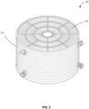
- FIG. 3 illustrates a perspective view of an adsorption container 300 of the direct air capture unit 100 of FIG. 1 .
- the adsorption container 300 has a shell 302.
- the shell 302 is a solid structure.
- the shell 302 is made from corrugated steel, with other materials possible.
- the adsorption container 300 has a cylindrical shape. In other embodiments, the adsorption container 300 may have different shapes, such as cuboid, cube, pentagonal prism, hexagonal prism, etc.
- the adsorption container 300 has a plurality of adsorption segments 304 that are arranged within the shell 302. In the illustrated embodiment, the adsorption container 300 has twenty adsorption segments 304. In other embodiments, the adsorption container 300 may have more or less than twenty adsorption segments 304 as desired.
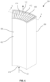
- FIG. 4 illustrates a perspective view of one adsorption segment 304 of the plurality of adsorption segments 304 of FIG. 3 .
- the adsorption segment 304 includes a frame 402.
- the frame 402 has a first closed side 404 and a second closed side 406 that is opposite to the first closed side 404.
- a hollow interior 408 is defined between the first closed side 404 and the second closed side 406.
- the frame 402 has a first open side 410 and a second open side 412 that is opposite to the first open side 410 for the air flow 122 passing through the adsorption segment 304.
- a filter plate 414 is installed in the hollow interior 408 of the frame 402.
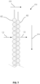
- FIG. 5 illustrates a section view of the adsorption segment 304 of FIG. 4 along a direction of A-A.
- the adsorption segment 304 has a plurality of first rods 502 that are disposed at the first open side 410 between the first closed side 404 and the second closed side 406 and a plurality of second rods 504 that are disposed at the second open side 412 between the first closed side 404 and the second closed side 406.
- the plurality of first rods 502 and the plurality of second rods 504 are offset from one another along the first open side 410 and the second open side 412.
- the filter plate 414 is a single continues plate.
- the filter plate 414 is folded alternatively over the plurality of first rods 502 and the plurality of second rods 504 forming an undulating profile along the first open side 410 and the second open side 412.
- Two adjacent portions of the filter plate 414 form a V shape between the first open side 410 and the second open side 412.
- the filter plate 414 has a thickness between 5 mm to 25 mm, preferably between 5 mm to 15 mm, with other dimensions possible.
- FIG. 6 illustrates a section view of the filter plate 414 of the adsorption segment 304 of FIG. 4 .
- the filter plate 414 is installed in the frame 402 in a vertical direction.
- the filter plate 414 includes a filter layer 602 having a first mesh 604 and a second mesh 606.
- the first mesh 604 has a first thickness and the second mesh 606 has a second thickness.
- the first mesh 604 is made of a first porous material having a plurality of first apertures across the first thickness which define a plurality of first flow passages.
- the second mesh 606 is made of a second porous material having a plurality of second apertures across the second thickness that define a plurality of second flow passages.
- the first mesh 604 and the second mesh 606 include wires to define the plurality of first apertures and the plurality of second apertures.
- the wire has a diameter between 0.05 mm to 0.2 mm, the plurality of first apertures and the plurality of second apertures have a diameter between 0.2 mm to 0.5 mm, with other dimensions possible.
- the first mesh 604 and the second mesh 606 may be made from the same material, such as synthetic fibers of polyamide mesh, stainless steel mesh, aluminum mesh, etc.
- the first mesh 604 and the second mesh 606 may be made from different materials.
- the first mesh 604 and the second mesh 606 are bonded together at a plurality of separated bonding locations 616 along a length direction 614.
- a plurality of pockets 608 are defined between the first mesh 604 and second mesh 606 and are separated from each other by the plurality of bonding locations 616.
- the first mesh 604 and the second mesh 606 may be bonded together by any suitable methods, such as ultrasound welding, heat wedge welding, sewing, or glue.
- Each pocket 608 of the plurality of pockets 608 is filled with a quantity of sorbent 610.
- the sorbent 610 fills a first volume within the pocket 608 when the sorbent 610 has not adsorbed water.
- the sorbent 610 swells when the sorbent 610 has adsorbed water.
- the sorbent 610 then fills a second volume within the pocket 608.
- the second volume is larger than the first volume.
- the sorbent 610 is fully filled within the pocket 608.
- a volume of the pocket 608 changes in response to the volume change of the sorbent 610 which changes with the water content.
- the first mesh 604 and the second mesh 606 are made of stretching materials that allow the volume change of the pocket 608.
- the sorbent 610 includes granular materials and amine-based materials, with other materials possible.
- the sorbent 610 is formed in bead type, such as spherical bead type, with other types possible.
- a diameter of the spherical bead type is between 0.1 mm to 1.5 mm, with other dimensions possible.
- the filter layer 602 has a width defined between the first mesh 604 and the second mesh 606 in a width direction 618.
- the air flow 122 passes through the filter layer 602 in the width direction 618.
- the width varies along the length direction 614 having a plurality of minimums and a plurality of maximums in an alternative manner.
- the plurality of minimums are at the plurality of bonding locations 616.
- the plurality of maximums are between adjacent minimums.
- a peripheral border 612 is defined at a peripheral area of the filter layer 602.
- the peripheral border 612 are formed by bonding the first mesh 604 and the second mesh 606 together in a designed length without pocket 608 therebetween.
- the peripheral border 612 can be used for embedment of structural elements, such as steel wires.
- FIG. 7 illustrates a section view of a further filter plate 414 of the adsorption segment 304 of FIG. 4 .
- the filter plate 414 is installed in the frame 402 in a vertical direction.
- the filter plate 414 includes a first filter layer 602 and a second filter layer 602.
- the first filter layer 602 and the second filter layer 602 are the same, with other configurations possible.
- the second filter layer 602 is attached to the first filter layer 602 with the plurality of minimums of the filter layer 602 align with the plurality of maximums of the first filter layer 602 in the width direction 618.
- the filter plate 414 thus has a substantial even width along the length direction 614 compared with the filter plate 414 having a single filter layer 602 in FIG. 6 .
- the filter plate 414 of FIG. 7 reduces the chance of the air flow 122 bypassing the sorbent 610.
- the plurality of walls 802 have a linear shape between the first mesh 604 and the second mesh 606 and are perpendicular to the first mesh 604 and the second mesh 606.
- the plurality of walls 802 may have non-linear shape between the first mesh 604 and the second mesh 606 and/or have an oblique angle with respect to the first mesh 604 and the second mesh 606, respectively.
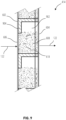
- FIG. 9 illustrates a section view of yet another further filter plate 414 of the adsorption segment 304 of FIG. 4 .
- the filter plate 414 is installed in the frame 402 in a vertical direction.
- the filter plate 414 has a filter layer 602.
- the filter layer 602 includes a plurality of pockets 608 between a first mesh 604 and a second mesh 606. Each pocket 608 of the plurality of pockets 608 is filled with the sorbent 610.
- the air flow 122 passes through the sorbent 610 from the first mesh 604 to the second mesh 606.
- the pocket 608 is partially filled with the sorbent 610 which defines a cavity 902 within the pocket 608.
- the sorbent 610 swells when the sorbent 610 has adsorbed water.
- the cavity 902 allows the sorbent 610 to swell.
- a volume of the pocket 608 is not changed in response to the volume change of the sorbent 610. This feature brings benefit when the first mesh 604 and the second mesh 606 are made of stiffer materials.
- a portion of the pocket 608 is coved by a solid plate 904.
- the portion is a part of the first mesh 604 that is an edge of the cavity 902.
- the solid plate 904 inhibits the air flow 122 flowing through the cavity 902 and forces the air flow 122 to pass through the sorbent 610.
- the solid plate 904 is installed on an inner surface of the first mesh 604 inside the pocket 608. It is possible that the solid plate 904 may be installed on an outer surface of the first mesh 604 outside of the pocket 608.
- FIG. 6 to FIG. 9 illustrate the filter plate 414 is installed in the frame 402 in either a vertical direction or a horizontal direction.
- the filter plate 414 may be oriented in an oblique direction, or any desired directions.
- the plurality of pockets 608 forms a pattern on the filter plate 414.
- FIG. 10 illustrates the plurality of pockets 608 forms a horizontal pattern.
- FIG. 11 illustrates the plurality of pockets 608 forms a vertical pattern.
- FIG. 12 illustrates the plurality of pockets 608 forms a cross pattern.
- FIG. 13 illustrates the plurality of pockets 608 forms a fish bone pattern.
- FIG. 14 illustrates the plurality of pockets 608 forms a honeycomb pattern.
- FIG. 15 illustrates the plurality of pockets 608 forms an elongated honeycomb pattern. It is possible that the pockets 608 may form any other patterns that are desired.
- FIG. 16 illustrates a perspective view of a device 1600 for manufacturing a filter plate 414 of the adsorption segment 304 of FIG. 4 .
- the device 1600 includes a plurality of first rollers 1602 and a plurality of second rollers 1604.
- the plurality of first rollers 1602 are separated from and arranged next to each other.
- the plurality of second rollers 1604 are separated from and arranged next to each other.
- Each first roller 1602 of the plurality of first rollers 1602 includes a first circumferential edge 1606 and a first circumferential region 1608 that has a smaller diameter than the first circumferential edge 1606.
- the first circumferential region 1608 is located between the first circumferential regions 1608 of adjacent first rollers 1602.
- Each second roller 1604 of the plurality of second rollers 1604 includes a second circumferential edge 1610 and a second circumferential region 1612 that has a smaller diameter than the second circumferential edge 1610.
- the second circumferential region 1612 is located between the second circumferential edges 1610 of adjacent second rollers 1604.
- the plurality of first rollers 1602 and the plurality of second roller 1604 are positioned adjacent one another such that each first circumferential edge 1606 is aligned with a respective second circumferential edge 1610 and each first circumferential region 1608 is aligned with a respective second circumferential region 1612.
- the plurality of first rollers 1602 and the plurality of second rollers 1604 are V-shaped rollers, with other configurations possible.
- a plurality of tubes 1614 are positioned between the plurality of first rollers 1602 and the plurality of second rollers 1604. Each tube 1614 of the plurality of tubes 1614 is positioned at one first circumferential region 1608 of the plurality of first circumferential regions 1608 and one second circumferential region 1612 of the plurality of second circumferential regions 1612.
- a sealer 1616 is positioned at a distance from the plurality of first rollers 1602 and the plurality of second rollers 1604.
- the sealer 1616 can be any suitable sealing machines to seal the first mesh 604 and the second mesh 606.
- a first mesh 604 and a second mesh 606 are fed between the plurality of first rollers 1602 and the plurality of second rollers 1604.
- the plurality of first circumferential edge 1606 and the plurality of second circumferential edge 1610 bond the first mesh 604 with the second mesh 606 forming a plurality of first seals.
- a plurality of pockets 608 are formed between the first mesh 604, the second mesh 606, and the plurality of first seals.
- the sorbent 610 is filled into the plurality of pockets 608 through the plurality of tubes 1614.
- the sealer 1616 seals the first mesh 604 and the second mesh 606 forming a second seal when a designed length of the pockets 608 reaches.
- the second seal is not parallel to the first seals.
- the filter plate 414 is cut when a designed length of the filter plate 414 reaches.
- the third roller 1702 includes a third circumferential edge 1706.
- the fourth roller 1704 includes a fourth circumferential edge 1708.
- the third roller 1702 and the fourth roller 1704 are positioned adjacent one another such that the third circumferential edge 1706 and the fourth circumferential edge 1708 are aligned to one another.
- the third roller 1702 and the fourth roller 1704 are V-shaped rollers, with other configurations possible.
- a mesh 1710 is fed between the third roller 1702 and the fourth roller 1704.
- the mesh 1710 is folded by the third circumferential edge 1706 and the fourth circumferential edge 1708 to a first mesh 604 and second mesh 606.
- the first roller 1602 and the second roller 1604 bonds the first mesh 604 with the second mesh 606 forming a first seal.
- a pocket 608 is formed between the first mesh 604, the second mesh 606, and the first seal.
- the sorbent is filled into the pocket 608 through the tube 1614.
- the sealer 1616 seals the first mesh 604 and the second mesh 606 forming a second seal when a designed length of the pocket 608 reaches.
- the second seal is not parallel to the first seal.
- the filter plate 414 is cut when a designed length of the filter plate 414 reaches.
- the device 1700 includes one first roller 1602 and one second roller 1604 to form a single pocket 608 in a row. It is possible that the device 1700 may have a plurality of first rollers 1602 and a plurality of second rollers 1604 to form a plurality of pockets 608 in a row.
- the air flow 122 is drawn by the fan 114 into the housing 102 of the direct air capture unit 100 through the louvered sidings 118.
- the air flow 122 is then drawn by the fan 114 into the plurality of frames 402 of the plurality of adsorption segments 304.
- the air flow 122 contacts the sorbent 610 in the filter plate 414 installed in the plurality of adsorption segments 304 to adsorb the CO 2 .
- the air flow 122 is drawn by the fan 114 to exit the direct air capture unit 100 through the opening 112.
- Each frame 402 of the plurality of frames 402 allows the filter plate 414 to be easily installed inside the adsorption container 300 and rapidly replaced when needed. During replacement, the filter plate 414 is removed from the frame 402 and a new filter plate 414 is installed into the frame 402 so that the frame 402 is reused. The rapid replacement of the filter plate 414 reduces the downtime of the direct air capture unit 100 and reduces installation time of a new or refurbished direct air capture unit 100.
- the filter plate 414 can be changed in some adsorption segments 304 or some adsorption containers 300 while the adsorption process is performing in the remaining adsorption segments 304 or the remaining adsorption containers 300.
- the filter plate 414 is installed in the frame 402 around the plurality of first rods 502 and the plurality of second rods 504 in an undulating profile which allows more mass of sorbent 610 being contained within the frame 402 and at the same time the less thickness of the filter plate 414 and less pressure drop.
- the thickness of the filter plate 414 is between 5 mm to 15 mm
- the pressure drop through the filter plate 414 is between 100 Pa to 350 Pa, preferably between 100 Pa to 250 Pa
- the area of the filter plate 414 and mass of the sorbent 610 within the frame 402 are increased due to the undulating profile.
- the electrical power that is needed to operate the direct air capture unit 100 is reduced which is based on the area and the thickness of the filter plate 414.
- the undulating profile of the filter plate 414 also allows a higher sorbent 610 to frame 402 mass ratio which reduces thermal mass inside of the frame 402. This allows more energy savings during the desorption process.
- the design of the filter plate 414 allows the filter plate 414 operating under a harsh conditions and withstanding medias, such as water, steam, CO 2 , ambient air, etc., in a cyclic process.
- the cyclic process may repeat many thousands of times per year, for example, over 8000 cycles per year.
- the operation temperature of the filter plate 414 can be between -20°C to 100°C, the absolute operation pressure can be between 0.02 Bar to 1 Bar.
- the sorbent 610 may be replaced in a shorter period of time, such as every one to three years.
- the frame 402, the first mesh 604, and the second mesh 606 may be replaced in a longer period of time, such as every twenty to twenty five years.
- the device 1600 and device 1700 allow an automated and continues filling the sorbent 610 and manufacturing the filter plate 414. A production cost of the filter plate 414 is thus reduced.
Landscapes
- Chemical & Material Sciences (AREA)
- Engineering & Computer Science (AREA)
- Analytical Chemistry (AREA)
- General Chemical & Material Sciences (AREA)
- Oil, Petroleum & Natural Gas (AREA)
- Chemical Kinetics & Catalysis (AREA)
- Separation Of Gases By Adsorption (AREA)
Abstract
An adsorption segment (304) includes a filter plate (414) including a filter layer (602), the filter layer (602) including a first mesh (604) having a first thickness, the first mesh (604) defining a plurality of first flow passages through the first thickness, the plurality of first flow passages selected to allow passing through an air flow (122), a second mesh (606) having a second thickness, the second mesh (606) defining a plurality of second flow passages through the second thickness, the plurality of second flow passages selected to allow passing through the air flow (122), the second mesh (606) bonded with the first mesh (604) to define a plurality of pockets (608), each pocket (608) separated from the remaining pockets (608), a sorbent (610) positioned in each pocket (608) and selected to adsorb carbon dioxide from the air flow (122), and a frame (402), the filter plate (414) being folded in the frame (402).
Description
- Gas separation by adsorption is an industrial method for the removal of a specific gaseous component from a gas mixture. One application is removal of carbon dioxide (CO2) from gas streams such as, flue or exhaust gases, industrial waste gases, biogas, or even atmospheric air. The process for CO2 capturing from air is known as direct air capture. The direct air capture process is to have a solid sorbent to which the CO2 molecules can adsorb through reactions with amine groups. During adsorption, air needs to be moved around a sorbent to provide the CO2 that can be adsorbed. During desorption, the sorbent needs to be enclosed in a container so that the released CO2 can be captured. To desorb, the temperature of the sorbent container is raised, and the partial pressure of the CO2 is lowered. The latter can be done by purging with another medium and/or lowering the absolute pressure in the sorbent container.
- Typically, steam is used for both purging and heating of the sorbent. At the start of the desorption phase, the air pressure in the sorbent container is lower by use of a vacuum pump, thereby lowering the amount of air that is mixed with the CO2 to be delivered by the direct air capture unit. Fan which is needed for moving air flow, such as ambient air, is one of the major power consumers. The other major consumer is the power needed to supply the heat needed for desorption. The service cost for exchange of sorbent is the other one of the major frequent recurrent operational expenses, both in terms of labor and downtime of the direct air capture unit.
- In one aspect, an adsorption segment includes a filter plate including a filter layer, the filter layer including a first mesh having a first thickness, the first mesh defining a plurality of first flow passages through the first thickness, the plurality of first flow passages selected to allow passing through an air flow, a second mesh having a second thickness, the second mesh defining a plurality of second flow passages through the second thickness, the plurality of second flow passages selected to allow passing through the air flow, the second mesh bonded with the first mesh to define a plurality of pockets, each pocket separated from the remaining pockets, a sorbent positioned in each pocket and selected to adsorb carbon dioxide from the air flow, and a frame, the filter plate being folded in the frame.
- In one aspect, a device for manufacturing a filter layer, the device including a first roller having a first circumferential edge and a first circumferential region that has a smaller diameter than the first circumferential edge, a second roller having a second circumferential edge and a second circumferential region that has a smaller diameter than the second circumferential edge, the first roller and the second roller positioned adjacent one another such that the first circumferential edge and the second circumferential edge and the first circumferential region and the second circumferential region are aligned to one another, and a sealer positioned at a distance from the first roller and the second roller.
- In one aspect, a method for manufacturing a filter plate, the method including feeding a first mesh and a second mesh between a first roller and a second roller to bond the first mesh with the second mesh forming a first seal, a pocket formed between the first mesh and the second mesh, injecting a sorbent into the pocket by a tube arranged between the first roller and the second roller, and sealing the pocket by a sealer forming a second seal that is not parallel to the first seal.
- To easily identify the discussion of any particular element or act, the most significant digit or digits in a reference number refer to the figure number in which that element is first introduced.
-
FIG. 1 illustrates a perspective external view of a direct air capture unit. -
FIG. 2 illustrates a perspective internal view of the direct air capture unit ofFIG. 1 . -
FIG. 3 illustrates a perspective view of an adsorption container of the direct air capture unit ofFIG. 1 . -
FIG. 4 illustrates a perspective view of an adsorption segment of the adsorption container ofFIG. 3 . -
FIG. 5 illustrates a section view of the adsorption segment ofFIG. 4 . -
FIG. 6 illustrates a section view of a filter plate of the adsorption segment ofFIG. 4 . -
FIG. 7 illustrates a section view of a further filter plate of the adsorption segment ofFIG. 4 . -
FIG. 8 illustrates a section view of another further filter plate of the adsorption segment ofFIG. 4 . -
FIG. 9 illustrates a section view of yet another further filter plate of the adsorption segment ofFIG. 4 . -
FIG. 10 illustrates a pattern of pockets of the filter plate of the adsorption segment ofFIG. 4 . -
FIG. 11 illustrates a pattern of pockets of the filter plate of the adsorption segment ofFIG. 4 . -
FIG. 12 illustrates a pattern of pockets of the filter plate of the adsorption segment ofFIG. 4 . -
FIG. 13 illustrates a pattern of pockets of the filter plate of the adsorption segment ofFIG. 4 . -
FIG. 14 illustrates a pattern of pockets of the filter plate of the adsorption segment ofFIG. 4 . -
FIG. 15 illustrates a pattern of pockets of the filter plate of the adsorption segment ofFIG. 4 . -
FIG. 16 illustrates a perspective view of a device for manufacturing the filter plate. -
FIG. 17 illustrates a perspective view of a device for manufacturing the filter plate. - Before any embodiments of the invention are explained in detail, it is to be understood that the invention is not limited in its application to the details of construction and the arrangement of components set forth in this description or illustrated in the following drawings. The invention is capable of other embodiments and of being practiced or of being carried out in various ways. Also, it is to be understood that the phraseology and terminology used herein is for the purpose of description and should not be regarded as limiting.
- Various technologies that pertain to systems and methods will now be described with reference to the drawings, where like reference numerals represent like elements throughout. The drawings discussed below, and the various embodiments used to describe the principles of the present disclosure in this patent document are by way of illustration only and should not be construed in any way to limit the scope of the disclosure. Those skilled in the art will understand that the principles of the present disclosure may be implemented in any suitably arranged apparatus. It is to be understood that functionality that is described as being carried out by certain system elements may be performed by multiple elements. Similarly, for instance, an element may be configured to perform functionality that is described as being carried out by multiple elements. The numerous innovative teachings of the present application will be described with reference to exemplary non-limiting embodiments.
- Also, it should be understood that the words or phrases used herein should be construed broadly, unless expressly limited in some examples. For example, the terms "including", "having", and "comprising", as well as derivatives thereof, mean inclusion without limitation. The singular forms "a", "an", and "the" are intended to include the plural forms as well, unless the context clearly indicates otherwise. Further, the term "and/or" as used herein refers to and encompasses any and all possible combinations of one or more of the associated listed items. The term "or" is inclusive, meaning and/or, unless the context clearly indicates otherwise. The phrases "associated with" and "associated therewith" as well as derivatives thereof, may mean to include, be included within, interconnect with, contain, be contained within, connect to or with, couple to or with, be communicable with, cooperate with, interleave, juxtapose, be proximate to, be bound to or with, have, have a property of, or the like. Furthermore, while multiple embodiments or constructions may be described herein, any features, methods, steps, components, etc. described with regard to one embodiment are equally applicable to other embodiments absent a specific statement to the contrary.
- Also, although the terms "first", "second", "third" and so forth may be used herein to refer to various elements, information, functions, or acts, these elements, information, functions, or acts should not be limited by these terms. Rather these numeral adjectives are used to distinguish different elements, information, functions or acts from each other. For example, a first element, information, function, or act could be termed a second element, information, function, or act, and, similarly, a second element, information, function, or act could be termed a first element, information, function, or act, without departing from the scope of the present disclosure.
- In addition, the term "adjacent to" may mean that an element is relatively near to but not in contact with a further element or that the element is in contact with the further portion, unless the context clearly indicates otherwise. Further, the phrase "based on" is intended to mean "based, at least in part, on" unless explicitly stated otherwise. Terms "about" or "substantially" or like terms are intended to cover variations in a value that are within normal industry manufacturing tolerances for that dimension. If no industry standard is available, a variation of twenty percent would fall within the meaning of these terms unless otherwise stated.
-
FIG. 1 illustrates a perspective external view of a directair capture unit 100. The directair capture unit 100 includes ahousing 102 that encloses a plurality of internal components which are shown inFIG. 2 . In the illustrated embodiment, the directair capture unit 100 is a cuboid. In other embodiments, the directair capture unit 100 may have shapes other than cuboid, such as cube, pentagonal prism, hexagonal prism, cylinder, etc. - The
housing 102 has abottom surface 104, atop surface 106 opposite to thebottom surface 104, and aside surface 108 extending between thebottom surface 104 and thetop surface 106. Thebottom surface 104 is placed on aground surface 110. Thetop surface 106 has anopening 112 in which afan 114 is placed. Alouver panel 116 is also placed in theopening 112 to inhibit water from entering thehousing 102. Theside surface 108 has a plurality oflouvered sidings 118 that are placed adjacent to each other. Eachlouvered siding 118 of the plurality oflouvered sidings 118 has a plurality ofgaps 120 to allow anair flow 122 entering thehousing 102. Theair flow 122 includes ambient air. -
FIG. 2 illustrates a perspective internal view of the directair capture unit 100 ofFIG. 1 with thehousing 102 being removed for illustration purpose. The directair capture unit 100 has asorbent bed 202. Acentral axis 206 extends from a center of thesorbent bed 202. Thesorbent bed 202 has a circular shape, with other configurations possible, such as rectangular, square, oval, etc. - The
sorbent bed 202 has a plurality ofholes 204 circumferentially distributed in thesorbent bed 202 with respect to thecentral axis 206. Eachhole 204 of the plurality ofholes 204 has a cylindrical shape, with other configurations possible, such as cuboid, cube, pentagonal prism, hexagonal prism, etc. The plurality ofholes 204 are circumferentially arranged in two distinct circles in thesorbent bed 202. In other embodiments, the plurality ofholes 204 may be circumferentially arranged in one circle or more than circles in thesorbent bed 202. An adsorption container 300 (shown inFIG. 3 ) can be installed in eachhole 204 for adsorbing carbon dioxide in theair flow 122 when theair flow 122 flows through theadsorption container 300. -
FIG. 3 illustrates a perspective view of anadsorption container 300 of the directair capture unit 100 ofFIG. 1 . Theadsorption container 300 has ashell 302. Theshell 302 is a solid structure. Theshell 302 is made from corrugated steel, with other materials possible. Theadsorption container 300 has a cylindrical shape. In other embodiments, theadsorption container 300 may have different shapes, such as cuboid, cube, pentagonal prism, hexagonal prism, etc. - The
adsorption container 300 has a plurality ofadsorption segments 304 that are arranged within theshell 302. In the illustrated embodiment, theadsorption container 300 has twentyadsorption segments 304. In other embodiments, theadsorption container 300 may have more or less than twentyadsorption segments 304 as desired. -
FIG. 4 illustrates a perspective view of oneadsorption segment 304 of the plurality ofadsorption segments 304 ofFIG. 3 . Theadsorption segment 304 includes aframe 402. Theframe 402 has a firstclosed side 404 and a secondclosed side 406 that is opposite to the firstclosed side 404. Ahollow interior 408 is defined between the firstclosed side 404 and the secondclosed side 406. - The
frame 402 has a firstopen side 410 and a secondopen side 412 that is opposite to the firstopen side 410 for theair flow 122 passing through theadsorption segment 304. Afilter plate 414 is installed in thehollow interior 408 of theframe 402. -
FIG. 5 illustrates a section view of theadsorption segment 304 ofFIG. 4 along a direction of A-A. Theadsorption segment 304 has a plurality offirst rods 502 that are disposed at the firstopen side 410 between the firstclosed side 404 and the secondclosed side 406 and a plurality ofsecond rods 504 that are disposed at the secondopen side 412 between the firstclosed side 404 and the secondclosed side 406. The plurality offirst rods 502 and the plurality ofsecond rods 504 are offset from one another along the firstopen side 410 and the secondopen side 412. - The
filter plate 414 is a single continues plate. Thefilter plate 414 is folded alternatively over the plurality offirst rods 502 and the plurality ofsecond rods 504 forming an undulating profile along the firstopen side 410 and the secondopen side 412. Two adjacent portions of thefilter plate 414 form a V shape between the firstopen side 410 and the secondopen side 412. Thefilter plate 414 has a thickness between 5 mm to 25 mm, preferably between 5 mm to 15 mm, with other dimensions possible. -
FIG. 6 illustrates a section view of thefilter plate 414 of theadsorption segment 304 ofFIG. 4 . Thefilter plate 414 is installed in theframe 402 in a vertical direction. Thefilter plate 414 includes afilter layer 602 having afirst mesh 604 and asecond mesh 606. Thefirst mesh 604 has a first thickness and thesecond mesh 606 has a second thickness. Thefirst mesh 604 is made of a first porous material having a plurality of first apertures across the first thickness which define a plurality of first flow passages. Thesecond mesh 606 is made of a second porous material having a plurality of second apertures across the second thickness that define a plurality of second flow passages. Thefirst mesh 604 and thesecond mesh 606 include wires to define the plurality of first apertures and the plurality of second apertures. The wire has a diameter between 0.05 mm to 0.2 mm, the plurality of first apertures and the plurality of second apertures have a diameter between 0.2 mm to 0.5 mm, with other dimensions possible. Thefirst mesh 604 and thesecond mesh 606 may be made from the same material, such as synthetic fibers of polyamide mesh, stainless steel mesh, aluminum mesh, etc. Thefirst mesh 604 and thesecond mesh 606 may be made from different materials. - The
first mesh 604 and thesecond mesh 606 are bonded together at a plurality of separatedbonding locations 616 along alength direction 614. A plurality ofpockets 608 are defined between thefirst mesh 604 andsecond mesh 606 and are separated from each other by the plurality ofbonding locations 616. Thefirst mesh 604 and thesecond mesh 606 may be bonded together by any suitable methods, such as ultrasound welding, heat wedge welding, sewing, or glue. - Each
pocket 608 of the plurality ofpockets 608 is filled with a quantity ofsorbent 610. Thesorbent 610 fills a first volume within thepocket 608 when thesorbent 610 has not adsorbed water. Thesorbent 610 swells when thesorbent 610 has adsorbed water. Thesorbent 610 then fills a second volume within thepocket 608. The second volume is larger than the first volume. In the embodiment illustrated inFIG. 6 , thesorbent 610 is fully filled within thepocket 608. A volume of thepocket 608 changes in response to the volume change of thesorbent 610 which changes with the water content. Thefirst mesh 604 and thesecond mesh 606 are made of stretching materials that allow the volume change of thepocket 608. Thesorbent 610 includes granular materials and amine-based materials, with other materials possible. Thesorbent 610 is formed in bead type, such as spherical bead type, with other types possible. A diameter of the spherical bead type is between 0.1 mm to 1.5 mm, with other dimensions possible. - The
filter layer 602 has a width defined between thefirst mesh 604 and thesecond mesh 606 in awidth direction 618. Theair flow 122 passes through thefilter layer 602 in thewidth direction 618. The width varies along thelength direction 614 having a plurality of minimums and a plurality of maximums in an alternative manner. The plurality of minimums are at the plurality ofbonding locations 616. The plurality of maximums are between adjacent minimums. - A
peripheral border 612 is defined at a peripheral area of thefilter layer 602. Theperipheral border 612 are formed by bonding thefirst mesh 604 and thesecond mesh 606 together in a designed length withoutpocket 608 therebetween. Theperipheral border 612 can be used for embedment of structural elements, such as steel wires. -
FIG. 7 illustrates a section view of afurther filter plate 414 of theadsorption segment 304 ofFIG. 4 . Thefilter plate 414 is installed in theframe 402 in a vertical direction. Thefilter plate 414 includes afirst filter layer 602 and asecond filter layer 602. Thefirst filter layer 602 and thesecond filter layer 602 are the same, with other configurations possible. Thesecond filter layer 602 is attached to thefirst filter layer 602 with the plurality of minimums of thefilter layer 602 align with the plurality of maximums of thefirst filter layer 602 in thewidth direction 618. Thefilter plate 414 thus has a substantial even width along thelength direction 614 compared with thefilter plate 414 having asingle filter layer 602 inFIG. 6 . Thefilter plate 414 ofFIG. 7 reduces the chance of theair flow 122 bypassing thesorbent 610. -
FIG. 8 illustrates a section view of anotherfurther filter plate 414 of theadsorption segment 304 ofFIG. 4 . Thefilter plate 414 is installed in theframe 402 in a horizontal direction. thefilter plate 414 has afilter layer 602. Thefilter layer 602 includes afirst mesh 604 and asecond mesh 606 that are bonded together by a plurality ofwalls 802 disposed between thefirst mesh 604 and thesecond mesh 606. The plurality ofpockets 608 are defined between thefirst mesh 604, thesecond mesh 606, and the plurality ofwalls 802. The plurality ofwalls 802 make thefilter layer 602 having a substantial even width along thelength direction 614. In the embodiment illustrated inFIG. 8 , the plurality ofwalls 802 have a linear shape between thefirst mesh 604 and thesecond mesh 606 and are perpendicular to thefirst mesh 604 and thesecond mesh 606. In other embodiments, the plurality ofwalls 802 may have non-linear shape between thefirst mesh 604 and thesecond mesh 606 and/or have an oblique angle with respect to thefirst mesh 604 and thesecond mesh 606, respectively. -
FIG. 9 illustrates a section view of yet anotherfurther filter plate 414 of theadsorption segment 304 ofFIG. 4 . Thefilter plate 414 is installed in theframe 402 in a vertical direction. Thefilter plate 414 has afilter layer 602. Thefilter layer 602 includes a plurality ofpockets 608 between afirst mesh 604 and asecond mesh 606. Eachpocket 608 of the plurality ofpockets 608 is filled with thesorbent 610. Theair flow 122 passes through thesorbent 610 from thefirst mesh 604 to thesecond mesh 606. - The
pocket 608 is partially filled with thesorbent 610 which defines acavity 902 within thepocket 608. Thesorbent 610 swells when thesorbent 610 has adsorbed water. Thecavity 902 allows thesorbent 610 to swell. A volume of thepocket 608 is not changed in response to the volume change of thesorbent 610. This feature brings benefit when thefirst mesh 604 and thesecond mesh 606 are made of stiffer materials. - A portion of the
pocket 608 is coved by asolid plate 904. The portion is a part of thefirst mesh 604 that is an edge of thecavity 902. Thesolid plate 904 inhibits theair flow 122 flowing through thecavity 902 and forces theair flow 122 to pass through thesorbent 610. In the embodiment illustrated inFIG. 9 , thesolid plate 904 is installed on an inner surface of thefirst mesh 604 inside thepocket 608. It is possible that thesolid plate 904 may be installed on an outer surface of thefirst mesh 604 outside of thepocket 608. -
FIG. 6 to FIG. 9 illustrate thefilter plate 414 is installed in theframe 402 in either a vertical direction or a horizontal direction. In other embodiments, thefilter plate 414 may be oriented in an oblique direction, or any desired directions. - The plurality of
pockets 608 forms a pattern on thefilter plate 414.FIG. 10 illustrates the plurality ofpockets 608 forms a horizontal pattern.FIG. 11 illustrates the plurality ofpockets 608 forms a vertical pattern.FIG. 12 illustrates the plurality ofpockets 608 forms a cross pattern.FIG. 13 illustrates the plurality ofpockets 608 forms a fish bone pattern.FIG. 14 illustrates the plurality ofpockets 608 forms a honeycomb pattern.FIG. 15 illustrates the plurality ofpockets 608 forms an elongated honeycomb pattern. It is possible that thepockets 608 may form any other patterns that are desired. -
FIG. 16 illustrates a perspective view of adevice 1600 for manufacturing afilter plate 414 of theadsorption segment 304 ofFIG. 4 . Thedevice 1600 includes a plurality offirst rollers 1602 and a plurality ofsecond rollers 1604. The plurality offirst rollers 1602 are separated from and arranged next to each other. The plurality ofsecond rollers 1604 are separated from and arranged next to each other. - Each
first roller 1602 of the plurality offirst rollers 1602 includes a firstcircumferential edge 1606 and a firstcircumferential region 1608 that has a smaller diameter than the firstcircumferential edge 1606. The firstcircumferential region 1608 is located between the firstcircumferential regions 1608 of adjacentfirst rollers 1602. Eachsecond roller 1604 of the plurality ofsecond rollers 1604 includes a secondcircumferential edge 1610 and a secondcircumferential region 1612 that has a smaller diameter than the secondcircumferential edge 1610. The secondcircumferential region 1612 is located between the secondcircumferential edges 1610 of adjacentsecond rollers 1604. The plurality offirst rollers 1602 and the plurality ofsecond roller 1604 are positioned adjacent one another such that each firstcircumferential edge 1606 is aligned with a respective secondcircumferential edge 1610 and each firstcircumferential region 1608 is aligned with a respective secondcircumferential region 1612. The plurality offirst rollers 1602 and the plurality ofsecond rollers 1604 are V-shaped rollers, with other configurations possible. - A plurality of
tubes 1614 are positioned between the plurality offirst rollers 1602 and the plurality ofsecond rollers 1604. Eachtube 1614 of the plurality oftubes 1614 is positioned at one firstcircumferential region 1608 of the plurality of firstcircumferential regions 1608 and one secondcircumferential region 1612 of the plurality of secondcircumferential regions 1612. - A
sealer 1616 is positioned at a distance from the plurality offirst rollers 1602 and the plurality ofsecond rollers 1604. Thesealer 1616 can be any suitable sealing machines to seal thefirst mesh 604 and thesecond mesh 606. - In manufacturing process, a
first mesh 604 and asecond mesh 606 are fed between the plurality offirst rollers 1602 and the plurality ofsecond rollers 1604. The plurality of firstcircumferential edge 1606 and the plurality of secondcircumferential edge 1610 bond thefirst mesh 604 with thesecond mesh 606 forming a plurality of first seals. A plurality ofpockets 608 are formed between thefirst mesh 604, thesecond mesh 606, and the plurality of first seals. Thesorbent 610 is filled into the plurality ofpockets 608 through the plurality oftubes 1614. Thesealer 1616 seals thefirst mesh 604 and thesecond mesh 606 forming a second seal when a designed length of thepockets 608 reaches. The second seal is not parallel to the first seals. Thefilter plate 414 is cut when a designed length of thefilter plate 414 reaches. -
FIG. 17 illustrates a perspective view of adevice 1700 for manufacturing afilter plate 414 of theadsorption segment 304 ofFIG. 4 . Thedevice 1700 includes athird roller 1702 and afourth roller 1704 that are disposed at a distance from thefirst roller 1602 and thesecond roller 1604. Thethird roller 1702 andfourth roller 1704 are oriented perpendicular to thefirst roller 1602 and thesecond roller 1604. Thetube 1614 is disposed between thethird roller 1702 and thefourth roller 1704 and thefirst roller 1602 and thesecond roller 1604. - The
third roller 1702 includes a thirdcircumferential edge 1706. Thefourth roller 1704 includes a fourthcircumferential edge 1708. Thethird roller 1702 and thefourth roller 1704 are positioned adjacent one another such that the thirdcircumferential edge 1706 and the fourthcircumferential edge 1708 are aligned to one another. Thethird roller 1702 and thefourth roller 1704 are V-shaped rollers, with other configurations possible. - In manufacturing process, a
mesh 1710 is fed between thethird roller 1702 and thefourth roller 1704. Themesh 1710 is folded by the thirdcircumferential edge 1706 and the fourthcircumferential edge 1708 to afirst mesh 604 andsecond mesh 606. Thefirst roller 1602 and thesecond roller 1604 bonds thefirst mesh 604 with thesecond mesh 606 forming a first seal. Apocket 608 is formed between thefirst mesh 604, thesecond mesh 606, and the first seal. The sorbent is filled into thepocket 608 through thetube 1614. Thesealer 1616 seals thefirst mesh 604 and thesecond mesh 606 forming a second seal when a designed length of thepocket 608 reaches. The second seal is not parallel to the first seal. Thefilter plate 414 is cut when a designed length of thefilter plate 414 reaches. - The
device 1700 includes onefirst roller 1602 and onesecond roller 1604 to form asingle pocket 608 in a row. It is possible that thedevice 1700 may have a plurality offirst rollers 1602 and a plurality ofsecond rollers 1604 to form a plurality ofpockets 608 in a row. - During operation, the
air flow 122 is drawn by thefan 114 into thehousing 102 of the directair capture unit 100 through thelouvered sidings 118. Theair flow 122 is then drawn by thefan 114 into the plurality offrames 402 of the plurality ofadsorption segments 304. Theair flow 122 contacts thesorbent 610 in thefilter plate 414 installed in the plurality ofadsorption segments 304 to adsorb the CO2. After adsorption, theair flow 122 is drawn by thefan 114 to exit the directair capture unit 100 through theopening 112. - Each
frame 402 of the plurality offrames 402 allows thefilter plate 414 to be easily installed inside theadsorption container 300 and rapidly replaced when needed. During replacement, thefilter plate 414 is removed from theframe 402 and anew filter plate 414 is installed into theframe 402 so that theframe 402 is reused. The rapid replacement of thefilter plate 414 reduces the downtime of the directair capture unit 100 and reduces installation time of a new or refurbished directair capture unit 100. Thefilter plate 414 can be changed in someadsorption segments 304 or someadsorption containers 300 while the adsorption process is performing in the remainingadsorption segments 304 or the remainingadsorption containers 300. - The
filter plate 414 is installed in theframe 402 around the plurality offirst rods 502 and the plurality ofsecond rods 504 in an undulating profile which allows more mass ofsorbent 610 being contained within theframe 402 and at the same time the less thickness of thefilter plate 414 and less pressure drop. For example, the thickness of thefilter plate 414 is between 5 mm to 15 mm, the pressure drop through thefilter plate 414 is between 100 Pa to 350 Pa, preferably between 100 Pa to 250 Pa, the area of thefilter plate 414 and mass of thesorbent 610 within theframe 402 are increased due to the undulating profile. As such, the electrical power that is needed to operate the directair capture unit 100 is reduced which is based on the area and the thickness of thefilter plate 414. The undulating profile of thefilter plate 414 also allows ahigher sorbent 610 to frame 402 mass ratio which reduces thermal mass inside of theframe 402. This allows more energy savings during the desorption process. - The design of the
filter plate 414 allows thefilter plate 414 operating under a harsh conditions and withstanding medias, such as water, steam, CO2, ambient air, etc., in a cyclic process. The cyclic process may repeat many thousands of times per year, for example, over 8000 cycles per year. The operation temperature of thefilter plate 414 can be between -20°C to 100°C, the absolute operation pressure can be between 0.02 Bar to 1 Bar. - During operation, the
sorbent 610 may be replaced in a shorter period of time, such as every one to three years. Theframe 402, thefirst mesh 604, and thesecond mesh 606 may be replaced in a longer period of time, such as every twenty to twenty five years. - The
device 1600 anddevice 1700 allow an automated and continues filling thesorbent 610 and manufacturing thefilter plate 414. A production cost of thefilter plate 414 is thus reduced. - Although an exemplary embodiment of the present disclosure has been described in detail, those skilled in the art will understand that various changes, substitutions, variations, and improvements disclosed herein may be made without departing from the spirit and scope of the disclosure in its broadest form.
- None of the description in the present application should be read as implying that any particular element, step, act, or function is an essential element, which must be included in the claim scope: the scope of patented subject matter is defined only by the allowed claims. Moreover, none of these claims are intended to invoke a means plus function claim construction unless the exact words "means for" are followed by a participle.
Claims (15)
- An adsorption segment (304) comprising:a filter plate (414) comprising a filter layer (602), the filter layer (602) comprising:a first mesh (604) having a first thickness, the first mesh (604) defining a plurality of first flow passages through the first thickness, the plurality of first flow passages selected to allow passing through an air flow (122);a second mesh (606) having a second thickness, the second mesh (606) defining a plurality of second flow passages through the second thickness, the plurality of second flow passages selected to allow passing through the air flow (122), the second mesh (606) bonded with the first mesh (604) to define a plurality of pockets (608), each pocket (608) separated from the remaining pockets (608);a sorbent (610) positioned in each pocket (608) and selected to adsorb carbon dioxide from the air flow (122); anda frame (402), the filter plate (414) being folded in the frame (402).
- The adsorption segment (304) of claim 1, wherein the air flow (122) passes through the filter layer (602) in a width direction (618), wherein a width of the filter layer (602) varies along a length direction (614) to define a plurality of minimums and a plurality of maximums, and wherein the filter plate (414) further comprises a second filter layer (602) that is attached to the filter layer (602) with the plurality of minimums of the second filter layer (602) align with the plurality of maximums of the first filter layer (602).
- The adsorption segment (304) of claim 1 or 2, wherein the filter layer (602) comprises a plurality of walls (802) that are disposed between the first mesh (604) and the second mesh (606) to bond the first mesh (604) with the second mesh (606) and to define the plurality of pockets (608).
- The adsorption segment (304) of any one of claims 1 to 3, wherein the plurality of pockets (608) forms a pattern, and wherein the pattern is selected from the group consisting of a horizontal pattern, a vertical pattern, a cross pattern, a fish bone pattern, a honeycomb pattern, and an elongated honeycomb pattern.
- The adsorption segment (304) of any one of claims 1 to 4, wherein each pocket (608) contains a quantity of sorbent (610) that fills a first volume when the sorbent (610) has not adsorbed water, wherein the sorbent (610) fills a second volume when the sorbent (610) has adsorbed water, and where the second volume is larger than the first volume.
- The adsorption segment (304) of claim 5, wherein a volume of the pocket (608) changes in response to a volume change of the sorbent (610) from the first volume to the second volume.
- The adsorption segment (304) of any one of claims 1 to 6, wherein a portion of each pocket (608) of the plurality of pockets (608) is covered by a solid plate (904).
- The adsorption segment (304) of any one of claims 1 to 7, wherein the filter layer (602) comprises a peripheral border (612) formed by solidly bonding a peripheral area of the first mesh (604) and the second mesh (606).
- The adsorption segment (304) of any one of claims 1 to 8, wherein the frame (402) comprises:a first closed side (404),a second closed side (406) opposite to the first closed side (404),a first open side (410),a second open side (412) opposite to the first open side (410),a plurality of first rods (502) disposed at the first open side (410) between the first closed side (404) and the second closed side (406),a plurality of second rods (504) disposed at the second open side (412) between the first closed side (404) and the second closed side (406), wherein the filter plate (414) is a single continues plate and is folded alternatively over the plurality of first rods (502) and the plurality of second rods (504) forming an undulating profile.
- The adsorption segment (304) of claim 9, wherein the plurality of first rods (502) and the plurality of second rods (504) are offset from one another along the first open side (410) and the second open side (412).
- A device (1600, 1700) for manufacturing a filter plate (414), the device (1600, 1700) comprising:a first roller (1602) having a first circumferential edge (1606) and a first circumferential region (1608) that has a smaller diameter than the first circumferential edge (1606);a second roller (1604) having a second circumferential edge (1610) and a second circumferential region (1612) that has a smaller diameter than the second circumferential edge (1610), the first roller (1602) and the second roller (1604) positioned adjacent one another such that the first circumferential edge (1606) and the second circumferential edge (1610) and the first circumferential region (1608) and the second circumferential region (1612) are aligned to one another, wherein the first circumferential edge (1606) and the second circumferential edge (1610) form a first seal;a tube (1614) arranged between the first roller (1602) and the second roller (1604); anda sealer (1616) positioned at a distance from the first roller (1602) and the second roller (1604), wherein the sealer (1616) forms a second seal that is not parallel to the first seal.
- The device (1600, 1700) of claim 11, wherein the first roller (1602) comprises a plurality of separated first rollers (1602) arranged next to each other, wherein each of the separated first rollers (1602) comprises a first circumferential edge (1606) and a first circumferential region (1608) that has a smaller diameter than the first circumferential edge (1606), wherein the second roller (1604) comprises a plurality of separated second rollers (1604) arranged next to each, and wherein each of the separated second rollers (1604) comprises a second circumferential edge (1610) and a second circumferential region (1612) that has a smaller diameter than the second circumferential edge (1610).
- The device (1600, 1700) of claim 11 or 12, further comprising a third roller (1702) and a fourth roller (1704) disposed at a distance from the first roller (1602) and the second roller (1604) and oriented perpendicular to the first roller (1602) and the second roller (1604), wherein the third roller (1702) comprises a third circumferential edge (1706) and the fourth roller (1704) comprises a fourth circumferential edge (1708), and wherein the third roller (1702) and the fourth roller (1704) are positioned adjacent one another such that the third circumferential edge (1706) and the fourth circumferential edge (1708) are aligned to one another.
- A method for operating the device (1600, 1700) of any one of claims 11 to 13, the method comprising:feeding a first mesh (604) and a second mesh (606) between the first roller (1602) and the second roller (1604) to bond the first mesh (604) with the second mesh (606) forming the first seal, a pocket (608) formed between the first mesh (604) and the second mesh (606);injecting a sorbent (610) into the pocket (608) by the tube (1614) arranged between the first roller (1602) and the second roller (1604); andsealing the pocket (608) by the sealer (1616) forming the second seal that is not parallel to the first seal.
- The method of claim 14, further comprising feeding a mesh (1710) between the third roller (1702) and the fourth roller (1704) to fold the mesh (1710) into the first mesh (604) and the second mesh (606).
Priority Applications (6)
| Application Number | Priority Date | Filing Date | Title |
|---|---|---|---|
| EP23179375.3A EP4477290A1 (en) | 2023-06-15 | 2023-06-15 | Adsorption segment for direct air capture unit |
| PCT/EP2024/064694 WO2024256168A1 (en) | 2023-06-15 | 2024-05-29 | Adsorption segment for direct air capture unit |
| AU2024305007A AU2024305007A1 (en) | 2023-06-15 | 2024-05-29 | Adsorption segment for direct air capture unit |
| EP24730279.7A EP4705004A1 (en) | 2023-06-15 | 2024-05-29 | Adsorption segment for direct air capture unit |
| CN202480039431.0A CN121311291A (en) | 2023-06-15 | 2024-05-29 | Adsorption section for direct air capture unit |
| CL2025003916A CL2025003916A1 (en) | 2023-06-15 | 2025-12-12 | Adsorption segment for direct air capture unit. |
Applications Claiming Priority (1)
| Application Number | Priority Date | Filing Date | Title |
|---|---|---|---|
| EP23179375.3A EP4477290A1 (en) | 2023-06-15 | 2023-06-15 | Adsorption segment for direct air capture unit |
Publications (1)
| Publication Number | Publication Date |
|---|---|
| EP4477290A1 true EP4477290A1 (en) | 2024-12-18 |
Family
ID=86851391
Family Applications (2)
| Application Number | Title | Priority Date | Filing Date |
|---|---|---|---|
| EP23179375.3A Withdrawn EP4477290A1 (en) | 2023-06-15 | 2023-06-15 | Adsorption segment for direct air capture unit |
| EP24730279.7A Pending EP4705004A1 (en) | 2023-06-15 | 2024-05-29 | Adsorption segment for direct air capture unit |
Family Applications After (1)
| Application Number | Title | Priority Date | Filing Date |
|---|---|---|---|
| EP24730279.7A Pending EP4705004A1 (en) | 2023-06-15 | 2024-05-29 | Adsorption segment for direct air capture unit |
Country Status (5)
| Country | Link |
|---|---|
| EP (2) | EP4477290A1 (en) |
| CN (1) | CN121311291A (en) |
| AU (1) | AU2024305007A1 (en) |
| CL (1) | CL2025003916A1 (en) |
| WO (1) | WO2024256168A1 (en) |
Families Citing this family (1)
| Publication number | Priority date | Publication date | Assignee | Title |
|---|---|---|---|---|
| WO2026112261A2 (en) | 2024-11-22 | 2026-05-28 | Parker-Hannifin Corporation | Low pressure drop sorbents, filtration medias, filters & filtration systems |
Citations (5)
| Publication number | Priority date | Publication date | Assignee | Title |
|---|---|---|---|---|
| WO1999015259A1 (en) * | 1997-09-19 | 1999-04-01 | Valtion Teknillinen Tutkimuskeskus | Filter for gases |
| US6402811B1 (en) * | 1999-12-30 | 2002-06-11 | Anthony E. Shanks | Non-dusting sorbent material filter |
| US20170326494A1 (en) * | 2013-04-18 | 2017-11-16 | Climeworks Ag | Low-pressure drop structure of particle adsorbent bed for adsorption gas separation process |
| CN110575731A (en) * | 2019-09-03 | 2019-12-17 | 中国辐射防护研究院 | A fiber material drawer type iodine adsorber |
| US20200001224A9 (en) * | 2013-04-18 | 2020-01-02 | Climeworks Ag | Low-pressure drop structure of particle adsorbent bed for improved adsorption gas separation process |
-
2023
- 2023-06-15 EP EP23179375.3A patent/EP4477290A1/en not_active Withdrawn
-
2024
- 2024-05-29 CN CN202480039431.0A patent/CN121311291A/en active Pending
- 2024-05-29 WO PCT/EP2024/064694 patent/WO2024256168A1/en not_active Ceased
- 2024-05-29 EP EP24730279.7A patent/EP4705004A1/en active Pending
- 2024-05-29 AU AU2024305007A patent/AU2024305007A1/en active Pending
-
2025
- 2025-12-12 CL CL2025003916A patent/CL2025003916A1/en unknown
Patent Citations (5)
| Publication number | Priority date | Publication date | Assignee | Title |
|---|---|---|---|---|
| WO1999015259A1 (en) * | 1997-09-19 | 1999-04-01 | Valtion Teknillinen Tutkimuskeskus | Filter for gases |
| US6402811B1 (en) * | 1999-12-30 | 2002-06-11 | Anthony E. Shanks | Non-dusting sorbent material filter |
| US20170326494A1 (en) * | 2013-04-18 | 2017-11-16 | Climeworks Ag | Low-pressure drop structure of particle adsorbent bed for adsorption gas separation process |
| US20200001224A9 (en) * | 2013-04-18 | 2020-01-02 | Climeworks Ag | Low-pressure drop structure of particle adsorbent bed for improved adsorption gas separation process |
| CN110575731A (en) * | 2019-09-03 | 2019-12-17 | 中国辐射防护研究院 | A fiber material drawer type iodine adsorber |
Also Published As
| Publication number | Publication date |
|---|---|
| AU2024305007A1 (en) | 2025-12-18 |
| CL2025003916A1 (en) | 2026-03-27 |
| WO2024256168A1 (en) | 2024-12-19 |
| CN121311291A (en) | 2026-01-09 |
| EP4705004A1 (en) | 2026-03-11 |
Similar Documents
| Publication | Publication Date | Title |
|---|---|---|
| US12268983B2 (en) | Adsorber structure for gas separation processes | |
| US10427086B2 (en) | Low-pressure drop structure of particle adsorbent bed for adsorption gas separation process | |
| EP2986357B1 (en) | Low-pressure drop structure of particle adsorbent bed for gas adsorption separation process | |
| JP2024518973A (en) | Gas-liquid contactor with packing for capturing carbon dioxide | |
| WO2018083109A1 (en) | Low-pressure drop structure of particle adsorbent bed for improved adsorption gas separation process | |
| CN102166499A (en) | Radial flow reactor | |
| WO2024256168A1 (en) | Adsorption segment for direct air capture unit | |
| US20250312726A1 (en) | A process for capture of carbon dioxide | |
| AU2012223554A1 (en) | Rapid temperature swing adsorption contactors for gas separation | |
| EP4477291A1 (en) | Adsorption segment for direct air capture unit | |
| GB2551310A (en) | A Gas treatment element and a method of forming a gas treatment element | |
| US8906140B2 (en) | Filtration module | |
| EP4378564A1 (en) | Adsorber structure for capturing gaseous components from a gas mixture | |
| US20250360451A1 (en) | A system for capture of carbon dioxide | |
| US11701601B2 (en) | Monolithic assembly integrating open cell structure with retaining partition | |
| US20240269601A1 (en) | Hot gas filtration with enhanced compartmental flow distribution via dual filter configurations | |
| WO2025031905A1 (en) | Modular adsorber structure for gas separation processes |
Legal Events
| Date | Code | Title | Description |
|---|---|---|---|
| PUAI | Public reference made under article 153(3) epc to a published international application that has entered the european phase |
Free format text: ORIGINAL CODE: 0009012 |
|
| STAA | Information on the status of an ep patent application or granted ep patent |
Free format text: STATUS: THE APPLICATION HAS BEEN PUBLISHED |
|
| AK | Designated contracting states |
Kind code of ref document: A1 Designated state(s): AL AT BE BG CH CY CZ DE DK EE ES FI FR GB GR HR HU IE IS IT LI LT LU LV MC ME MK MT NL NO PL PT RO RS SE SI SK SM TR |
|
| STAA | Information on the status of an ep patent application or granted ep patent |
Free format text: STATUS: THE APPLICATION IS DEEMED TO BE WITHDRAWN |
|
| 18D | Application deemed to be withdrawn |
Effective date: 20250619 |