EP4477282A1 - Mass displacement device in a racket for the practice of sports - Google Patents
Mass displacement device in a racket for the practice of sports Download PDFInfo
- Publication number
- EP4477282A1 EP4477282A1 EP24159940.6A EP24159940A EP4477282A1 EP 4477282 A1 EP4477282 A1 EP 4477282A1 EP 24159940 A EP24159940 A EP 24159940A EP 4477282 A1 EP4477282 A1 EP 4477282A1
- Authority
- EP
- European Patent Office
- Prior art keywords
- racket
- main tube
- central rod
- cap
- internal
- Prior art date
- Legal status (The legal status is an assumption and is not a legal conclusion. Google has not performed a legal analysis and makes no representation as to the accuracy of the status listed.)
- Granted
Links
Images


Classifications
-
- A—HUMAN NECESSITIES
- A63—SPORTS; GAMES; AMUSEMENTS
- A63B—APPARATUS FOR PHYSICAL TRAINING, GYMNASTICS, SWIMMING, CLIMBING, OR FENCING; BALL GAMES; TRAINING EQUIPMENT
- A63B60/00—Details or accessories of golf clubs, bats, rackets or the like
- A63B60/52—Details or accessories of golf clubs, bats, rackets or the like with slits
-
- A—HUMAN NECESSITIES
- A63—SPORTS; GAMES; AMUSEMENTS
- A63B—APPARATUS FOR PHYSICAL TRAINING, GYMNASTICS, SWIMMING, CLIMBING, OR FENCING; BALL GAMES; TRAINING EQUIPMENT
- A63B49/00—Stringed rackets, e.g. for tennis
- A63B49/02—Frames
- A63B49/035—Frames with easily dismountable parts, e.g. heads, shafts or grips
-
- A—HUMAN NECESSITIES
- A63—SPORTS; GAMES; AMUSEMENTS
- A63B—APPARATUS FOR PHYSICAL TRAINING, GYMNASTICS, SWIMMING, CLIMBING, OR FENCING; BALL GAMES; TRAINING EQUIPMENT
- A63B49/00—Stringed rackets, e.g. for tennis
- A63B49/02—Frames
- A63B49/08—Frames with special construction of the handle
-
- A—HUMAN NECESSITIES
- A63—SPORTS; GAMES; AMUSEMENTS
- A63B—APPARATUS FOR PHYSICAL TRAINING, GYMNASTICS, SWIMMING, CLIMBING, OR FENCING; BALL GAMES; TRAINING EQUIPMENT
- A63B60/00—Details or accessories of golf clubs, bats, rackets or the like
- A63B60/06—Handles
- A63B60/16—Caps; Ferrules
-
- A—HUMAN NECESSITIES
- A63—SPORTS; GAMES; AMUSEMENTS
- A63B—APPARATUS FOR PHYSICAL TRAINING, GYMNASTICS, SWIMMING, CLIMBING, OR FENCING; BALL GAMES; TRAINING EQUIPMENT
- A63B60/00—Details or accessories of golf clubs, bats, rackets or the like
- A63B60/06—Handles
- A63B60/22—Adjustable handles
- A63B60/24—Weighted handles
-
- A—HUMAN NECESSITIES
- A63—SPORTS; GAMES; AMUSEMENTS
- A63B—APPARATUS FOR PHYSICAL TRAINING, GYMNASTICS, SWIMMING, CLIMBING, OR FENCING; BALL GAMES; TRAINING EQUIPMENT
- A63B60/00—Details or accessories of golf clubs, bats, rackets or the like
- A63B60/42—Devices for measuring, verifying, correcting or customising the inherent characteristics of golf clubs, bats, rackets or the like, e.g. measuring the maximum torque a batting shaft can withstand
-
- A—HUMAN NECESSITIES
- A63—SPORTS; GAMES; AMUSEMENTS
- A63B—APPARATUS FOR PHYSICAL TRAINING, GYMNASTICS, SWIMMING, CLIMBING, OR FENCING; BALL GAMES; TRAINING EQUIPMENT
- A63B60/00—Details or accessories of golf clubs, bats, rackets or the like
- A63B60/48—Details or accessories of golf clubs, bats, rackets or the like with corrugated cross-section
-
- A—HUMAN NECESSITIES
- A63—SPORTS; GAMES; AMUSEMENTS
- A63B—APPARATUS FOR PHYSICAL TRAINING, GYMNASTICS, SWIMMING, CLIMBING, OR FENCING; BALL GAMES; TRAINING EQUIPMENT
- A63B2209/00—Characteristics of used materials
- A63B2209/10—Characteristics of used materials with adhesive type surfaces, i.e. hook and loop-type fastener
-
- A—HUMAN NECESSITIES
- A63—SPORTS; GAMES; AMUSEMENTS
- A63B—APPARATUS FOR PHYSICAL TRAINING, GYMNASTICS, SWIMMING, CLIMBING, OR FENCING; BALL GAMES; TRAINING EQUIPMENT
- A63B60/00—Details or accessories of golf clubs, bats, rackets or the like
- A63B60/50—Details or accessories of golf clubs, bats, rackets or the like with through-holes
Definitions
- the present disclosure refers to a patent application for a mass device applied to a racket for the practice of sports.
- rackets are required for the practice of many sports, and the user seeks the use of a racket that enhances their game and is easy to handle.
- Rackets for practicing sports are manufactured from a graphite module, or carbon fiber or glass fiber, or Kevlar (synthetic para-aramid fiber, very heat resistant), or are even composed of 100% 3K carbon with the new high-density soft EVA, with characteristics appropriate to each type of sport, with more or fewer holes in the body of the racket.
- the weight of the racket and the decrease of this weight also has an influence on the performance of the user, since the balance of said racket is fundamental to the dynamics of the game.
- the user then makes adaptations to the racket in order to optimize its performance during the sport.
- the applicant of the present invention has developed a mass displacement device, to provide rackets for any sporting modality, which is introduced into the racket handle, constituting an integrated system, which allows the adjustment of the balance point of the racket, providing the user with the best adjustment according to their convenience, before or during the match.
- the device consists of a main tube, which is housed inside the handle, according to the size and type of racket, and said tube is equipped with internal guides, through which a counterweight equipped with symmetrical grooves longitudinally opened on its external side slides, and, in its center, equipped with a through hole, with infinite thread, also longitudinally, through which the central rod passes, and the central rod, when activated in rotational movements, causes the counterweight to move longitudinally along the entire internal extension of the main tube, causing a change in the balance point of the racket.
- This central rod is activated by the user, at any time, before or during the match, through the protruding head on its upper part, thus composing a system for changing the balance point of the racket, towards the tip or handle, allowing the user to change their playing style from smooth to consistent or aggressive and vice versa.
- the central rod has a small smooth upper part and its remaining part is equipped with an infinite thread, to which a counterweight with infinite internal thread is coupled, and this counterweight is coupled, in its external part, to the internal wall of the main tube, through longitudinal symmetrical guides.
- the upper part of the central rod is equipped with a protruding head with grooves, comprising external grooves, or being hexagonal in shape, or having any other arrangement that can generate friction with the hands or fingers of the user, which will promote the rotational movement of the rod on its axis.
- the user by turning the protruding head of the central rod, both clockwise and counterclockwise, rotates the central rod on its axis and, consequently, makes the counterweight, which is attached to the internal symmetrical guides of the main tube, to move longitudinally within the main tube.
- the counterweight as it is attached to the internal symmetrical guides of the main tube, remains immobilized inside the racket handle until the user moves it, changing the balance of the racket as desired.
- the objective of the present patent is to integrate the rackets for the practice of sports with a mass displacement device, in any sport that uses rackets, that are easy to adjust by the user.
- the present patent refers to a "MASS DISPLACEMENT DEVICE IN A RACKET FOR THE PRACTICE OF SPORTS", more precisely, it is a device used to balance the weight of a racket (2) for the practice of sports and shift its balance, in order to improve the performance of the user.
- Said device comprises a hollow main tube (1), which is fixed by glue or any other adhesive means inside the racket handle (2), support flap (3) and internal thread (4) in its upper part, symmetrical guides (8) in high relief on its internal wall and, in its lower internal part, a centralized concave receptacle (9) for the conditioning and fitting of the central rod (10).
- the central rod (10) is composed, in its upper part, of a protruding head (14) comprising external grooves, hexagonal in shape, or having any other arrangement that can generate friction with the hands or fingers of the user, and with the body of said central rod (10) having a small smooth upper part (15), followed by a channel (16) in low relief around its entire circumference and the rest of its body equipped with an infinite thread (17), through which the counterweight (11) with infinite internal thread (12), and the lower part of the central rod (10) is convex in shape (18), so as to be conditioned and fitted into the concave receptacle (9) that exists in the lower internal part of the main tube (1), eliminating the possibility of lateral movement of said central rod (10).
- the counterweight (11), which moves along the entire length of the central rod (10), is equipped with an infinite internal thread (12) and symmetrical grooves (13) on its external part, with these symmetrical grooves (13) being fitted into the symmetrical guides (8) in high relief, located on the inside of the main tube (1).
- a cap (5) fixed or equipped with an external thread (7) is provided, which will be fixed or threaded into the internal thread (4) existing on the part upper part of the main tube (1), this cap (5) being equipped with a central hollow hole (6) with a smooth interior, through which the central rod (10) will be inserted, so that the small upper part (15) on the central rod (10) fits into the central hollow hole (6) of said cap (5), and the central rod (10) is secured to the cap (5) through a clip (19), inserted into the channel (16) in low relief existing on the central rod (10), so as not to allow vertical or lateral movement of said central rod (10) and leaving the part of the central rod (10) equipped with infinite thread (17) free for rotational movements in its axle.
- the main tube (1) is inserted inside the racket handle (2), being fixed by glue or any other adhesive means.
- the central rod (10) is inserted through the central hollow hole (6) in the cap (5), being fixed to said cap (5) by a clip (19) inserted in the channel (16) in the existing low relief in said central rod (10), and the counterweight (11) is threaded into the part of the central rod (10) equipped with infinite thread (17), and this assembly is inserted inside the main tube (1), until the convex-shaped lower part (18) of the central rod (10) is accommodated in the concave receptacle (9) existing in the lower internal part of the main tube (1), with the symmetrical low-relief external grooves (13) existing in said counterweight (11) fit into the symmetrical, high-relief internal guides (8) on the inner wall of the main tube (1), and the installation of the device in the racket is completed by screwing or fixing the cap (5) to the main tube (1), immobilizing the assembly and only allowing the rotational movement of the central rod (10) on its axis, both clockwise and counterclockwise.
- the user With the device fixed to the racket (2), the user, through the protruding head (14) of the central rod (10), can make rotational movements of said central rod (10), clockwise or counterclockwise, in order to move the counterweight (11) along the entire length of the part of the central rod (10) equipped with an infinite thread (17), quickly and effectively controlling the desired balance point for the racket (2).
Landscapes
- Health & Medical Sciences (AREA)
- General Health & Medical Sciences (AREA)
- Physical Education & Sports Medicine (AREA)
- Life Sciences & Earth Sciences (AREA)
- Biophysics (AREA)
- Golf Clubs (AREA)
Abstract
Description
- The present disclosure refers to a patent application for a mass device applied to a racket for the practice of sports.
- The use of rackets are required for the practice of many sports, and the user seeks the use of a racket that enhances their game and is easy to handle.
- Rackets for practicing sports are manufactured from a graphite module, or carbon fiber or glass fiber, or Kevlar (synthetic para-aramid fiber, very heat resistant), or are even composed of 100% 3K carbon with the new high-density soft EVA, with characteristics appropriate to each type of sport, with more or fewer holes in the body of the racket.
- There are rackets for the practice of sports with a technological device on the sides of the handle, which allows a consistent reduction of vibrations caused by the continuous impact of the ball, alleviating trauma in the wrist, elbow and shoulder of the player.
- Users can also change the stringing pressure, on those rackets that have strings, in order to maximize their hits on the ball, increasing or decreasing the speed of the ball.
- The weight of the racket and the decrease of this weight also has an influence on the performance of the user, since the balance of said racket is fundamental to the dynamics of the game.
- As rackets are manufactured in a standardized way, the user is unable to purchase a specific racket, that is already adapted to playing pattern of the user.
- The user then makes adaptations to the racket in order to optimize its performance during the sport.
- These adaptations are made to make the racket lighter or heavier, and are made by adding lead tapes to the head of the racket, or to its sides or throughout the heart of the racket.
- The application of extra weight to the racket seeks to find the best balance between the spinning speed and the weight of the racket, optimizing the performance of the player during the match. However, this practice is empirical and does not allow the user to recalibrate the balance of the racket throughout the match, as the weights are glued to the body of the racket, which makes it difficult to remove and/or adjust positioning.
- Document
US 4179121 teaches the construction of a round tube inside the racket, from the base, circulating throughout the "head" of the racket, this tube being divided into two chambers by valves. In the lower chamber, mercury or another very dense liquid is stored. The lower chamber communicates with the upper chamber through valves, and through centrifugal force and gravity, the liquid is directed between the two chambers, increasing the kinetic force exerted against the ball, providing a more powerful swing and improved play. This procedure also does not ensure better performance for the user, who does not have the option of calibrating the valves to allow the liquid to pass through the racket, altering its balance. Furthermore, the racket must be manufactured with the tube already inside, which restricts the options of the user, as they will not be able to choose their preferred model of racket on the market. - In order to overcome the problem of racket balance and allow the user to quickly make precise adjustments during the use of their racket, the applicant of the present invention, has developed a mass displacement device, to provide rackets for any sporting modality, which is introduced into the racket handle, constituting an integrated system, which allows the adjustment of the balance point of the racket, providing the user with the best adjustment according to their convenience, before or during the match.
- The device consists of a main tube, which is housed inside the handle, according to the size and type of racket, and said tube is equipped with internal guides, through which a counterweight equipped with symmetrical grooves longitudinally opened on its external side slides, and, in its center, equipped with a through hole, with infinite thread, also longitudinally, through which the central rod passes, and the central rod, when activated in rotational movements, causes the counterweight to move longitudinally along the entire internal extension of the main tube, causing a change in the balance point of the racket.
- This central rod is activated by the user, at any time, before or during the match, through the protruding head on its upper part, thus composing a system for changing the balance point of the racket, towards the tip or handle, allowing the user to change their playing style from smooth to consistent or aggressive and vice versa.
- The central rod has a small smooth upper part and its remaining part is equipped with an infinite thread, to which a counterweight with infinite internal thread is coupled, and this counterweight is coupled, in its external part, to the internal wall of the main tube, through longitudinal symmetrical guides.
- The upper part of the central rod is equipped with a protruding head with grooves, comprising external grooves, or being hexagonal in shape, or having any other arrangement that can generate friction with the hands or fingers of the user, which will promote the rotational movement of the rod on its axis.
- The user, by turning the protruding head of the central rod, both clockwise and counterclockwise, rotates the central rod on its axis and, consequently, makes the counterweight, which is attached to the internal symmetrical guides of the main tube, to move longitudinally within the main tube.
- By moving the counterweight through the main tube, making the counterweight to move internally along the entire length of the racket handle, the user quickly and easily chooses the best balance point to play their game.
- The counterweight, as it is attached to the internal symmetrical guides of the main tube, remains immobilized inside the racket handle until the user moves it, changing the balance of the racket as desired.
- Thus, the objective of the present patent is to integrate the rackets for the practice of sports with a mass displacement device, in any sport that uses rackets, that are easy to adjust by the user.
- To complement the present description in order to obtain a better understanding of the characteristics of the mass device applied to a racket and according to a preferred practical embodiment thereof, by way of example only, and not regarded as limiting, a set of drawings accompanies the description, in which:
-
Figure 1 represents a side view of the main tube mounted inside the racket handle. -
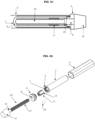
Figure 2 represents a side view of all parts of the mass device, in line. -
Figure 3A represents an internal side view of the main tube with the concave receptacle. -
Figure 3B represents a top view of the main tube with the internal symmetrical guides and flap. -
Figure 4 represents a side view of the central rod. -
Figure 5 represents a side view of the upper part of the central rod. -
Figure 6 represents a side view of the counterweight. -
Figure 07 represents a side view of the cap. - With reference to the illustrated drawings, the present patent [privilege] refers to a "MASS DISPLACEMENT DEVICE IN A RACKET FOR THE PRACTICE OF SPORTS", more precisely, it is a device used to balance the weight of a racket (2) for the practice of sports and shift its balance, in order to improve the performance of the user.
- Said device comprises a hollow main tube (1), which is fixed by glue or any other adhesive means inside the racket handle (2), support flap (3) and internal thread (4) in its upper part, symmetrical guides (8) in high relief on its internal wall and, in its lower internal part, a centralized concave receptacle (9) for the conditioning and fitting of the central rod (10).
- The central rod (10) is composed, in its upper part, of a protruding head (14) comprising external grooves, hexagonal in shape, or having any other arrangement that can generate friction with the hands or fingers of the user, and with the body of said central rod (10) having a small smooth upper part (15), followed by a channel (16) in low relief around its entire circumference and the rest of its body equipped with an infinite thread (17), through which the counterweight (11) with infinite internal thread (12), and the lower part of the central rod (10) is convex in shape (18), so as to be conditioned and fitted into the concave receptacle (9) that exists in the lower internal part of the main tube (1), eliminating the possibility of lateral movement of said central rod (10).
- The counterweight (11), which moves along the entire length of the central rod (10), is equipped with an infinite internal thread (12) and symmetrical grooves (13) on its external part, with these symmetrical grooves (13) being fitted into the symmetrical guides (8) in high relief, located on the inside of the main tube (1).
- To immobilize the central rod (10) in the main tube (1), a cap (5) fixed or equipped with an external thread (7) is provided, which will be fixed or threaded into the internal thread (4) existing on the part upper part of the main tube (1), this cap (5) being equipped with a central hollow hole (6) with a smooth interior, through which the central rod (10) will be inserted, so that the small upper part (15) on the central rod (10) fits into the central hollow hole (6) of said cap (5), and the central rod (10) is secured to the cap (5) through a clip (19), inserted into the channel (16) in low relief existing on the central rod (10), so as not to allow vertical or lateral movement of said central rod (10) and leaving the part of the central rod (10) equipped with infinite thread (17) free for rotational movements in its axle.
- The main tube (1) is inserted inside the racket handle (2), being fixed by glue or any other adhesive means.
- The central rod (10) is inserted through the central hollow hole (6) in the cap (5), being fixed to said cap (5) by a clip (19) inserted in the channel (16) in the existing low relief in said central rod (10), and the counterweight (11) is threaded into the part of the central rod (10) equipped with infinite thread (17), and this assembly is inserted inside the main tube (1), until the convex-shaped lower part (18) of the central rod (10) is accommodated in the concave receptacle (9) existing in the lower internal part of the main tube (1), with the symmetrical low-relief external grooves (13) existing in said counterweight (11) fit into the symmetrical, high-relief internal guides (8) on the inner wall of the main tube (1), and the installation of the device in the racket is completed by screwing or fixing the cap (5) to the main tube (1), immobilizing the assembly and only allowing the rotational movement of the central rod (10) on its axis, both clockwise and counterclockwise.
- With the device fixed to the racket (2), the user, through the protruding head (14) of the central rod (10), can make rotational movements of said central rod (10), clockwise or counterclockwise, in order to move the counterweight (11) along the entire length of the part of the central rod (10) equipped with an infinite thread (17), quickly and effectively controlling the desired balance point for the racket (2).
- Different embodiments and variations can be made to the present mass displacement device for rackets (2) for the practice of sports, including modifications in construction, size, materials, functional configurations, or relating to process steps and parameters, without departing from the scope of the invention, as defined in the appended claims.
Claims (4)
- Mass displacement device in a racket for the practice of sports, equipped with a protruding head (14) with external grooves, with hexagonal shape, or in another arrangement that may generate friction with the hands or fingers of the user,having a main tube (1) fixed by glue or other adhesive means inside the racket handle (2),characterized by having a hollow main tube (1) equipped, in its upper part, with an external support flap (3) and internal thread (4)where the cap (5) equipped with an external thread (7) and central hollow hole (6) will be threaded on,said main tube (1) being equipped on its internal wall and along the entire length of its body, with internal symmetrical guides (8) in high relief, and in its lower internal part, it is equipped with a centralized concave receptacle (9), for having a central rod (10) with counterweight (11) equipped with infinite internal thread (12) and symmetrical grooves (13) at the bottom relief, which will pass through the cap (5), being fixed to said cap (5) through a clip (19),said central rod (10) is composed, in its upper part, of a protruding head (14), being said body of said central rod (10) has a small smooth upper part (15), followed by a channel (16) in low relief throughout its circumference and the remainder of its body is equipped with an infinite thread (17), where the counterweight (11) is threaded, and the lower part of the central rod (10) has a convex shape (18).
- Mass displacement device in a racket for the practice of sports, according to the claim, characterized by the counterweight (11) being equipped with an infinite internal thread (12) and symmetrical grooves (13) in low relief on its external part.
- Mass displacement device in a racket for the practice of sports, according to any of the preceding claims, characterized in that the cap (5) is provided with an external thread (7) that will be threaded onto the internal thread (4) on the main tube (1) or fixed to said main tube (1) and a central hollow hole (6) with a smooth interior, through which the central rod (10) will be inserted.
- Mass displacement device in a racket for the practice of sports, according to any of the preceding claims, characterized in that the central rod (10) is inserted through the central hollow hole (6) in the cap (5), being fixed to the said cap (5) by a clip (19) inserted into the channel (16) in the low relief existing in said central rod (10) equipped with infinite thread (17), this assembly being inserted inside the main tube (1), with the cap (5) being threaded or fixed onto the main tube (1), until the convex-shaped lower part (18) of the central rod (10) fits into the concave receptacle (9) on the inner lower part of the main tube (1), with the external symmetrical grooves (13) of said counterweight (11) fitting into the internal symmetrical guides (8) on the internal wall of the main tube (1).
Applications Claiming Priority (1)
| Application Number | Priority Date | Filing Date | Title |
|---|---|---|---|
| BR102023011971 | 2023-06-16 |
Publications (2)
| Publication Number | Publication Date |
|---|---|
| EP4477282A1 true EP4477282A1 (en) | 2024-12-18 |
| EP4477282B1 EP4477282B1 (en) | 2026-08-19 |
Family
ID=90097547
Family Applications (1)
| Application Number | Title | Priority Date | Filing Date |
|---|---|---|---|
| EP24159940.6A Active EP4477282B1 (en) | 2023-06-16 | 2024-02-27 | Mass displacement device in a racket for the practice of sports |
Country Status (1)
| Country | Link |
|---|---|
| EP (1) | EP4477282B1 (en) |
Citations (5)
| Publication number | Priority date | Publication date | Assignee | Title |
|---|---|---|---|---|
| US4179121A (en) | 1977-11-22 | 1979-12-18 | Pedro Kelmanski | Tennis racket with adjustable weight |
| US5171011A (en) * | 1990-10-17 | 1992-12-15 | Squadroni Elpidio O | Handle with a pneumatic surface capable of being deformed |
| US7704160B2 (en) * | 2004-01-06 | 2010-04-27 | Balance-Certified Golf, Inc. | Apparatus for weighting golf club shaft |
| KR101143265B1 (en) * | 2010-04-30 | 2012-05-11 | 김선겸 | racket having Balance adjusting |
| JP2016518227A (en) * | 2013-05-17 | 2016-06-23 | エスエスジー インターナショナル,エルエルシー | Golf club shaft grip and internal weight system |
-
2024
- 2024-02-27 EP EP24159940.6A patent/EP4477282B1/en active Active
Patent Citations (5)
| Publication number | Priority date | Publication date | Assignee | Title |
|---|---|---|---|---|
| US4179121A (en) | 1977-11-22 | 1979-12-18 | Pedro Kelmanski | Tennis racket with adjustable weight |
| US5171011A (en) * | 1990-10-17 | 1992-12-15 | Squadroni Elpidio O | Handle with a pneumatic surface capable of being deformed |
| US7704160B2 (en) * | 2004-01-06 | 2010-04-27 | Balance-Certified Golf, Inc. | Apparatus for weighting golf club shaft |
| KR101143265B1 (en) * | 2010-04-30 | 2012-05-11 | 김선겸 | racket having Balance adjusting |
| JP2016518227A (en) * | 2013-05-17 | 2016-06-23 | エスエスジー インターナショナル,エルエルシー | Golf club shaft grip and internal weight system |
Also Published As
| Publication number | Publication date |
|---|---|
| EP4477282B1 (en) | 2026-08-19 |
Similar Documents
| Publication | Publication Date | Title |
|---|---|---|
| US6506128B1 (en) | Counterweighted golf club | |
| US6966846B2 (en) | Counterweighted golf club | |
| US8444500B2 (en) | Full swing weight training apparatus | |
| US8702530B2 (en) | Device for changing mass characteristics of a golf club | |
| US6007431A (en) | Golf clubs, and matched sets thereof, with frictionally-dissipative, vibration-damping counterweights | |
| US7758447B2 (en) | Golf club grip | |
| TWI442960B (en) | Golf club and golf club head including a structure that selectively controls the head sound | |
| US9192833B2 (en) | Golf club with improved weight distribution | |
| US7635310B2 (en) | Weighted golf club grips and shafts | |
| US5718643A (en) | Vibration dampening insert for golf clubs | |
| US2002108A (en) | Exercising device | |
| CN103520891B (en) | Golf clubs | |
| US20180290033A1 (en) | Weighted Golf Grip | |
| US7625295B2 (en) | Weighted trainer golf club | |
| EP3646927B1 (en) | Badminton racket | |
| US9861869B2 (en) | Universal lie-balanced putter system | |
| US20080009363A1 (en) | Weighted grip assembly for a golf club | |
| JP2006510395A (en) | Racket shaft and racket with the shaft | |
| US20250177830A1 (en) | Racket mass displacement device for sports practice | |
| US9089750B2 (en) | Butt-mounted shaft extension device | |
| US20130095947A1 (en) | Golf grip | |
| JP2010507429A (en) | Golf club | |
| BR202023011971Y1 (en) | MASS DISPLACEMENT DEVICE IN A RACKET FOR SPORTS PRACTICE | |
| US12605602B1 (en) | Bat swing training aid | |
| CN223601960U (en) | Pike racket capable of adjusting balance point |
Legal Events
| Date | Code | Title | Description |
|---|---|---|---|
| PUAI | Public reference made under article 153(3) epc to a published international application that has entered the european phase |
Free format text: ORIGINAL CODE: 0009012 |
|
| STAA | Information on the status of an ep patent application or granted ep patent |
Free format text: STATUS: THE APPLICATION HAS BEEN PUBLISHED |
|
| AK | Designated contracting states |
Kind code of ref document: A1 Designated state(s): AL AT BE BG CH CY CZ DE DK EE ES FI FR GB GR HR HU IE IS IT LI LT LU LV MC ME MK MT NL NO PL PT RO RS SE SI SK SM TR |
|
| STAA | Information on the status of an ep patent application or granted ep patent |
Free format text: STATUS: REQUEST FOR EXAMINATION WAS MADE |
|
| 17P | Request for examination filed |
Effective date: 20250617 |
|
| GRAP | Despatch of communication of intention to grant a patent |
Free format text: ORIGINAL CODE: EPIDOSNIGR1 |
|
| STAA | Information on the status of an ep patent application or granted ep patent |
Free format text: STATUS: GRANT OF PATENT IS INTENDED |
|
| RIC1 | Information provided on ipc code assigned before grant |
Ipc: A63B 49/035 20150101AFI20260226BHEP Ipc: A63B 49/08 20150101ALI20260226BHEP Ipc: A63B 60/16 20150101ALI20260226BHEP Ipc: A63B 60/24 20150101ALI20260226BHEP Ipc: A63B 60/42 20150101ALI20260226BHEP Ipc: A63B 60/48 20150101ALI20260226BHEP Ipc: A63B 60/52 20150101ALI20260226BHEP Ipc: A63B 60/50 20150101ALI20260226BHEP |
|
| INTG | Intention to grant announced |
Effective date: 20260311 |
|
| GRAS | Grant fee paid |
Free format text: ORIGINAL CODE: EPIDOSNIGR3 |
|
| GRAA | (expected) grant |
Free format text: ORIGINAL CODE: 0009210 |
|
| STAA | Information on the status of an ep patent application or granted ep patent |
Free format text: STATUS: THE PATENT HAS BEEN GRANTED |