EP4477132A1 - Shoe care apparatus - Google Patents
Shoe care apparatus Download PDFInfo
- Publication number
- EP4477132A1 EP4477132A1 EP24765931.1A EP24765931A EP4477132A1 EP 4477132 A1 EP4477132 A1 EP 4477132A1 EP 24765931 A EP24765931 A EP 24765931A EP 4477132 A1 EP4477132 A1 EP 4477132A1
- Authority
- EP
- European Patent Office
- Prior art keywords
- dehumidifying
- module
- care device
- flow path
- shoes
- Prior art date
- Legal status (The legal status is an assumption and is not a legal conclusion. Google has not performed a legal analysis and makes no representation as to the accuracy of the status listed.)
- Pending
Links
Images








Classifications
-
- A—HUMAN NECESSITIES
- A47—FURNITURE; DOMESTIC ARTICLES OR APPLIANCES; COFFEE MILLS; SPICE MILLS; SUCTION CLEANERS IN GENERAL
- A47L—DOMESTIC WASHING OR CLEANING; SUCTION CLEANERS IN GENERAL
- A47L23/00—Cleaning footwear
- A47L23/20—Devices or implements for drying footwear, also with heating arrangements
- A47L23/205—Devices or implements for drying footwear, also with heating arrangements with heating arrangements
-
- F—MECHANICAL ENGINEERING; LIGHTING; HEATING; WEAPONS; BLASTING
- F26—DRYING
- F26B—DRYING SOLID MATERIALS OR OBJECTS BY REMOVING LIQUID THEREFROM
- F26B21/00—Arrangements for supplying or controlling air or other gases for drying solid materials or objects
- F26B21/30—Controlling, e.g. regulating, parameters of gas supply
- F26B21/33—Humidity
- F26B21/331—Humidity by using sorbent or hygroscopic materials, e.g. chemical substances or molecular sieves
-
- A—HUMAN NECESSITIES
- A47—FURNITURE; DOMESTIC ARTICLES OR APPLIANCES; COFFEE MILLS; SPICE MILLS; SUCTION CLEANERS IN GENERAL
- A47B—TABLES; DESKS; OFFICE FURNITURE; CABINETS; DRAWERS; GENERAL DETAILS OF FURNITURE
- A47B61/00—Wardrobes
- A47B61/04—Wardrobes for shoes, hats, umbrellas, or the like
-
- F—MECHANICAL ENGINEERING; LIGHTING; HEATING; WEAPONS; BLASTING
- F26—DRYING
- F26B—DRYING SOLID MATERIALS OR OBJECTS BY REMOVING LIQUID THEREFROM
- F26B21/00—Arrangements for supplying or controlling air or other gases for drying solid materials or objects
- F26B21/006—Arrangements for supplying or controlling air or other gases for drying solid materials or objects with the air or gases passing through hollow spaces or cores within the materials or objects to be dried, e.g. tubes, pipes or bottles
-
- F—MECHANICAL ENGINEERING; LIGHTING; HEATING; WEAPONS; BLASTING
- F26—DRYING
- F26B—DRYING SOLID MATERIALS OR OBJECTS BY REMOVING LIQUID THEREFROM
- F26B21/00—Arrangements for supplying or controlling air or other gases for drying solid materials or objects
- F26B21/20—Circulating air or gases in closed cycles, e.g. wholly within the drying enclosure
- F26B21/202—Circulating air or gases in closed cycles, e.g. wholly within the drying enclosure with means for changing the flow pattern, e.g. by reversing gas flow or by moving the materials or objects through subsequent compartments, at least two of which have a different flow direction
- F26B21/208—Circulating air or gases in closed cycles, e.g. wholly within the drying enclosure with means for changing the flow pattern, e.g. by reversing gas flow or by moving the materials or objects through subsequent compartments, at least two of which have a different flow direction by air valves, movable baffles or nozzle arrangements
-
- F—MECHANICAL ENGINEERING; LIGHTING; HEATING; WEAPONS; BLASTING
- F26—DRYING
- F26B—DRYING SOLID MATERIALS OR OBJECTS BY REMOVING LIQUID THEREFROM
- F26B21/00—Arrangements for supplying or controlling air or other gases for drying solid materials or objects
- F26B21/20—Circulating air or gases in closed cycles, e.g. wholly within the drying enclosure
- F26B21/25—Circulating air or gases in closed cycles, e.g. wholly within the drying enclosure partly outside the drying enclosure
-
- F—MECHANICAL ENGINEERING; LIGHTING; HEATING; WEAPONS; BLASTING
- F26—DRYING
- F26B—DRYING SOLID MATERIALS OR OBJECTS BY REMOVING LIQUID THEREFROM
- F26B21/00—Arrangements for supplying or controlling air or other gases for drying solid materials or objects
- F26B21/30—Controlling, e.g. regulating, parameters of gas supply
- F26B21/35—Temperature; Pressure
-
- F—MECHANICAL ENGINEERING; LIGHTING; HEATING; WEAPONS; BLASTING
- F26—DRYING
- F26B—DRYING SOLID MATERIALS OR OBJECTS BY REMOVING LIQUID THEREFROM
- F26B21/00—Arrangements for supplying or controlling air or other gases for drying solid materials or objects
- F26B21/40—Arrangements for supplying or controlling air or other gases for drying solid materials or objects using gases other than air
- F26B21/45—Arrangements for supplying or controlling air or other gases for drying solid materials or objects using gases other than air using steam
- F26B21/452—Arrangements for supplying or controlling air or other gases for drying solid materials or objects using gases other than air using steam characterised by the steam generating means
-
- F—MECHANICAL ENGINEERING; LIGHTING; HEATING; WEAPONS; BLASTING
- F26—DRYING
- F26B—DRYING SOLID MATERIALS OR OBJECTS BY REMOVING LIQUID THEREFROM
- F26B21/00—Arrangements for supplying or controlling air or other gases for drying solid materials or objects
- F26B21/50—Ducting arrangements from the source of air or other gases to the materials or objects being dried
-
- F—MECHANICAL ENGINEERING; LIGHTING; HEATING; WEAPONS; BLASTING
- F26—DRYING
- F26B—DRYING SOLID MATERIALS OR OBJECTS BY REMOVING LIQUID THEREFROM
- F26B23/00—Heating arrangements
- F26B23/04—Heating arrangements using electric heating
-
- F—MECHANICAL ENGINEERING; LIGHTING; HEATING; WEAPONS; BLASTING
- F26—DRYING
- F26B—DRYING SOLID MATERIALS OR OBJECTS BY REMOVING LIQUID THEREFROM
- F26B25/00—Details of general application not covered by group F26B21/00 or F26B23/00
- F26B25/06—Chambers, containers, or receptacles
- F26B25/08—Parts thereof
- F26B25/12—Walls or sides; Doors
-
- F—MECHANICAL ENGINEERING; LIGHTING; HEATING; WEAPONS; BLASTING
- F26—DRYING
- F26B—DRYING SOLID MATERIALS OR OBJECTS BY REMOVING LIQUID THEREFROM
- F26B9/00—Machines or apparatus for drying solid materials or objects at rest or with only local agitation; Domestic airing cupboards
- F26B9/06—Machines or apparatus for drying solid materials or objects at rest or with only local agitation; Domestic airing cupboards in stationary drums or chambers
-
- A—HUMAN NECESSITIES
- A47—FURNITURE; DOMESTIC ARTICLES OR APPLIANCES; COFFEE MILLS; SPICE MILLS; SUCTION CLEANERS IN GENERAL
- A47F—SPECIAL FURNITURE, FITTINGS, OR ACCESSORIES FOR SHOPS, STOREHOUSES, BARS, RESTAURANTS OR THE LIKE; PAYING COUNTERS
- A47F3/00—Show cases or show cabinets
- A47F3/001—Devices for lighting, humidifying, heating, ventilation
Definitions
- the present invention relates to a shoe care device, and more particular, to a shoe care device that includes a dehumidifier for drying shoes, wherein the dehumidifier is regenerated.
- Shoes may get wet by a wearer's sweat, external contaminants, or rain or snow. Wearing such shoes may make the wearer uncomfortable, and in the condition, germs may also breed or stink in the shoes.
- a dehumidifying material may be used in a shoe care device, and the dehumidifying material may remove moisture to dry shoes.
- CN102131440A discloses a dishwasher including a reversibly dehydratable sorption material to dry washed items, wherein the sorption material, which may be made of silica gel or zeolite, is a particulate solid with a particle size of 1 to 6 mm and is used while filled in a sorption container.
- the sorption material which may be made of silica gel or zeolite, is a particulate solid with a particle size of 1 to 6 mm and is used while filled in a sorption container.
- the dishwasher of CN102131440A is configured to contain a sorption material in the form of particles filled in the sorption container and is capable of drying the items washed by the sorption material.
- a sorption material in the form of particles filled in the sorption container and is capable of drying the items washed by the sorption material.
- the sorption material particles with a particle size of 1 to 6 mm adhere to each other in the sorption container, air volume may decrease when air passes through the sorption material by a fan unit.
- CN102131440A which is related to a dishwasher, has the main purpose of washing dishes, and may not consider the air volume used when drying the washed items as a major factor.
- shoes or the like that are subject to care may be made of a material that absorbs water. Therefore, the inventors of the present disclosure would like to disclose a shoe care device that includes a dehumidifying material and has excellent shoe drying ability by maintaining sufficient air volume.
- the present disclosure is to provide a shoe care device that includes a dehumidifying part that can sufficiently come into contact with air while allowing smooth air flow in a flow path extending through the dehumidifying part so as to ensure smooth drying of shoes and regeneration of the dehumidifying part.
- the present disclosure is to provide a shoe care device in which the dehumidifying part is stably supported and can be easily replaced.
- the present disclosure is to provide a shoe care device in which, when the dehumidifier is placed below the area where shoes are placed, the drying of air by the dehumidifying part and the regeneration of the dehumidifying part are performed smoothly while minimizing the vertical height of the space where the dehumidifying part is disposed, and the temperature of the area where the shoes are placed can be prevented from rising to a predetermined temperature or higher.
- a shoe care device disclosed herein includes: an inner cabinet having an accommodation space configured to accommodate shoes; a module chamber including a first flow path that is in communication with the accommodation space, and a second flow path that is a space spaced apart from the first flow path; a blowing part configured to blow air from the first flow path toward the second flow path; a heating part configured to heat the air in the first flow path; and a dehumidifying part disposed between the first flow path and the second flow path.
- the dehumidifying part includes: a dehumidifying body made of a pulp material impregnated with a dehumidifying material and having an upper surface facing the first flow path and a lower surface facing the second flow path; and a plurality of dehumidifying through-holes provided through the dehumidifying body to allow air introduced into the upper surface to move toward the lower surface.
- the diameter of the dehumidifying through-holes and the interval between the dehumidifying through-holes may be similar in size.
- the diameter of the dehumidifying through-holes and the interval between the dehumidifying through-holes may be about 2 mm.
- the average interval between the dehumidifying through-holes may be 1/2 to 3/2 of the maximum length of the cross-sectional areas of the dehumidifying through-holes.
- the diameter of the dehumidifying through-holes may be 2 mm or more.
- the interval between the dehumidifying through-holes may be 2 mm or less.
- the upper surface is provided on the upper side of the dehumidifying body.
- the lower surface is provided on the lower side of the dehumidifying body.
- the dehumidifying through-holes may be inclined downward from the upper surface toward the lower surface.
- the upper surface and the lower surface may be orthogonal to the direction in which the dehumidifying through-holes extend.
- the blowing part, the heating part, the dehumidifying part provided inside the module chamber may be spaced apart from each other in the horizontal direction so as to reduce the vertical height of the module chamber.
- the angle formed by the upper surface and the lower surface with a horizontal plane may be 10 to 40 degrees.
- the angle formed by the dehumidifying through-holes with the horizontal plane may be 60 to 80 degrees.
- the module chamber may be provided below the accommodation space.
- the shoe care device may include a dehumidifying material housing provided inside the module chamber to support the dehumidifying part.
- the dehumidifying housing may include a support provided in a grid shape and in contact the lower surface; and a support wall extending upward from the edge of the support and surrounding the edge of the dehumidifying part.
- the upper side of the space surrounded by the support wall may be open to allow access to the dehumidifying part.
- the dehumidifying part may include a dehumidifying edge that is made of a sponge with a predetermined thickness and coupled to the edge of the dehumidifying body.
- the dehumidifying edge has an outer surface that is in close contact with the inner surface of the support wall.
- the dehumidifying part may have a maximum moisture content of 30 to 40% when used and a maximum moisture content of 60 to 75% when immersed in water.
- the maximum temperature of the first flow path heated by the heating part may be 95°C.
- the regeneration temperature of the dehumidifier may be 60 to 95°C.
- the dehumidifying part includes: a dehumidifying body made of a pulp material impregnated with a dehumidifying material and having an upper surface facing the first flow path and a lower surface facing the second flow path; and a plurality of dehumidifying through-holes provided through the dehumidifying body to allow air introduced into the upper surface to move toward the lower surface.
- the dehumidifying through-holes may be inclined downward from the upper surface toward the lower surface.
- the dehumidifying part since an increase in the flow path provided through the dehumidifying part is prevented, sufficient contact between the dehumidifying material and air in the dehumidifying part can be made while achieving smooth air flow, smooth drying of shoes and regeneration of the dehumidifying part can be achieved in the shoe care device, and changes in the drying cycle (moisture absorption mode) and regeneration cycle (regeneration mode) can be minimized.
- the dehumidifying part includes a dehumidifying edge coupled to the edge of the dehumidifying body and having an outer surface that is in close contact with the support wall of the dehumidifying housing. According to the embodiment of the present disclosure, the dehumidifying part is stably supported by the dehumidifying housing, smooth air flow through the dehumidifying through-holes in the dehumidifying part is achieved, and the dehumidifying part is easily replaced.
- the module chamber is provided below the receiving space, and the blowing part, the heating part, and the dehumidifying part provided inside the module chamber are spaced apart from each other in the horizontal direction.
- the maximum temperature of the first flow path heated by the heating part may be 95°C
- the regeneration temperature of the dehumidifying part may be 60 to 95°C.
- the present disclosure presents specifications of a dehumidifying material (zeolite) that ensures smooth air flow in a connection path in order to achieve smooth drying and regeneration of objects to be cared for (products made of cloth, fiber, leather, or the like, which may include shoes (including leather shoes, sneakers, and the like), bags, clothing, hats, dolls, and the like).
- zeolite a dehumidifying material that ensures smooth air flow in a connection path.
- the present disclosure constitutes a drying cycle and a regeneration cycle that can ensure a smooth air flow path.
- the present disclosure is to reduce flow path resistance by reflecting the honeycomb structure of zeolite as a dehumidifying material.
- the present disclosure is to ensure sufficient moisture absorption for drying.
- the present disclosure is to minimize drying time by minimizing changes in drying cycle and regeneration cycle.
- the present disclosure is to minimize shoe damage by lowering a regeneration temperature.
- a management device 1 according to an embodiment of the present disclosure will be described, and zeolite as a dehumidifying material will be described.
- a care device 1 of the present invention is commenced.
- the care device 1 may be configured to care the item so that the item becomes clean while the item is accommodated therein or a physical/chemical state of the item accommodated is improved.
- a first direction (X direction), a second direction (Y direction), and a third direction (Z direction) described in one embodiment of the present invention may be directions orthogonal to each other.
- Each of the first direction (X direction) and the second direction (Y direction) may be a direction parallel to the horizontal direction, and the third direction (Z direction) may be a direction parallel to the vertical direction.
- the second direction (Y direction) may be parallel to a front-rear direction.
- the second direction (Y direction) may be parallel to the left-right direction.
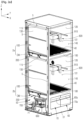
- FIG. 1a is a perspective view illustrating a shoes care device 1 according to one embodiment of the present invention.
- FIG. 1b is a perspective view of the shoes care device of FIG. 1a , when viewed from another direction, illustrating a state in which a door is opened.
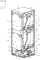
- FIG. 2a is a perspective view illustrating a state in which a part of the door and an outer cabinet are removed from the shoes care device of FIG. 1b .
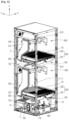
- FIG. 2b is a perspective view illustrating a state in which the shoes care device illustrated in FIG. 2a is viewed from another direction.
- a shoes care device 1 may include an outer cabinet 20, a door 30, an inner cabinet 100, and a machine room 50.
- the shoes care device 1 may include a main frame 5.
- the outer cabinet 20 and the door 30 may form an overall appearance of the shoes care device 1.
- the outside of the shoes care device 1 may be formed in a hexahedral shape. That is, while the outer cabinet 20 and the door 30 are coupled to each other and the door 30 is closed, the appearance of the shoes care device 1 may be formed in a hexahedral shape.
- the shoes care device 1 according to one embodiment of the present invention is not limited to such a shape and may have various three-dimensional shapes.
- the outer cabinet 20 may form an upper side surface, a left-side surface, a right-side surface, a rear surface, and bottom surfaces of the shoes care device 1.
- the main frame 5 may form an overall framework of the shoes care device 1.
- the main frame 5 may have a hexahedral structure.
- the outer cabinet 20 may be detachably fixed to the main frame 5.
- the outer cabinet 20 may include an outer rear plate 21, a first outer side plate 22, and a second outer side plate 23.
- the outer back plate 21, the first outer side plate 22, and the second outer side plate 23 may be formed integrally with each other, or the outer back plate 21, the first outer side plate 22, and the second outer side plate 23 may be individually formed.
- the outer rear plate 21 forms a vertically erected wall surface.
- the outer rear plate 21 may form a surface orthogonal to the first direction (X direction).
- the outer rear plate 21 may form a rear wall surface in the first direction (X direction) on the outer cabinet 20.
- the outer rear plate 21 may form a rear surface in the first direction (X direction) in the shoes care device 1.
- the outer rear plate 21 may form an entire outer rear surface of the shoes care device 1.
- the first outer side plate 22 and the second outer side plate 23 form vertically erected wall surfaces, respectively, and form opposing wall surfaces facing each other.
- the first outer side plate 22 is disposed at any one side with respect to a reference plane RP that is parallel to the first direction (X direction) as a horizontal direction and is a vertical plane.
- the second outer side plate 23 is disposed on the opposite side of the first outer side plate 22 with respect to the reference plane RP.
- the first outer side plate 22 may form a left wall surface of the outer cabinet 20, and the second outer side plate 23 may form a right wall surface of the outer cabinet 20.
- the outer cabinet 20 may be disposed outside the inner cabinet 100 and the machine room 50 to form an outer wall surface of the machine room 50.
- the outer cabinet 20 may form a wall separating the machine room 50 from the outside.
- the door 30 is configured to open and close the inside of the shoes care device 1.
- the door 30 may form any one surface of the shoes care device 1.
- the door 30 may form a left side or a right side of the shoes care device 1, or may form a front side of the shoes care device 1.
- the door 30 may be hinge-coupled.
- the door 30 may be hinge-coupled to the main frame 5. In another embodiment, the door 30 may be hinge-coupled to the outer cabinet 20, and in another embodiment, the door 30 may be hinge-coupled to the inner cabinet 100 and/or the machine room 50.
- a hinge rotation axis 31 of the door 30 may be formed in the vertical direction. That is, in the shoes care device 1, the door 30 may be configured to be rotatable bidirectionally around a rotation axis 31 in the vertical direction.
- the shoes care device 1 may include one door 30. In another embodiment, the shoes care device 1 may include two or more doors.
- each door may be individually rotated around each rotation axis.
- the first direction (X direction) described in one embodiment of the present invention may be parallel to or substantially parallel to the horizontal direction.
- the first direction (X direction) may be a direction from the rear of the shoes care device 1 to the front.
- the door 30 is formed in a front side of the shoes care device 1. That is, a surface on which the door 30 is formed in the shoes care device 1 is described as a front surface of the shoes care device 1.
- first direction is parallel to the front-rear direction
- second direction is parallel to the left-right direction
- third direction is parallel to the vertical direction.
- the inner cabinet 100 and the machine room 50 may be provided inside the outer cabinet 20.
- the inner cabinet 100 may be formed in a box shape, and a predetermined space may be formed therein.
- the space inside the inner cabinet 100 forms an accommodation space 101, and shoes S may be accommodated in the accommodation space 101.
- a plurality of shoes S may be disposed together in the accommodation space 101 of one inner cabinet 100.
- the inner cabinet 100 may be fixed to the main frame 5.
- the inner cabinet 100 has a predetermined size along the first direction (X direction), the second direction (Y direction), and the third direction (Z direction).
- the inner cabinet 100 is formed in the shape of a box opened to any one side.
- the inner cabinet 100 may be formed in a form opened to the front side of the shoes care device 1.
- the inner cabinet 100 may be configured to include a main opening 140.
- the main opening 140 may be provided to open the front side of the inner cabinet 100 in the first direction (X direction).
- the shoes may be disposed inside the inner cabinet 100 or withdrawn from the inner cabinet 100 through the main opening 140.
- the main opening 140 of the inner cabinet 100 may be closed or opened by the door 30.
- the inner cabinet 100 may include an inner rear plate 110, a first inner side plate 120, a second inner side plate 130, and an inner upper plate 115.
- the inner rear plate 110, the first inner side plate 120, the second inner side plate 130, and the inner upper plate 115 may be formed integrally with each other.
- the inner cabinet 100 may be made of a single material and be formed by injection molding.
- the inner rear plate 110 forms a vertically erected wall surface.
- the inner rear plate 110 may form a surface orthogonal to the first direction (X direction).
- the inner rear plate 110 may form a rear wall surface of the inner cabinet 100 in the first direction (X direction).
- the inner rear plate 110 may be formed parallel to the outer rear plate 21.
- the first inner side plate 120 and the second inner side plate 130 form vertically erected wall surfaces, respectively, and form opposing wall surfaces facing each other.
- the first inner side plate 120 is dispose on either side with respect to the reference plane RP that is parallel to the first direction (X direction) as the horizontal direction and is a vertical surface.
- the second inner side plate 130 is disposed on the opposite side of the first inner side plate 120 with respect to the reference plane RP.
- the first inner side plate 120 forms a left wall surface of the inner cabinet 100
- the second inner side plate 130 forms a right wall surface of the inner cabinet 100.
- the first inner side plate 120 may be formed parallel to the first outer side plate 22, and the second inner side plate 130 may be formed parallel to the second outer side plate 23.
- the inner cabinet 100 may have the form where a lower part thereof is opened. Accordingly, the inner cabinet 100 includes a lower opening 150 formed by opening the lower part thereof. When the inner cabinet 100 is formed in a hexahedral shape on the whole, the lower opening 150 may be formed large to form all or most of a lower surface of the inner cabinet 100.
- the shoes care device 1 is not used in a state in which an entire lower part of the inner cabinet 100 is opened, but is used in a state in which the inner cabinet 100 and a module housing 200 are coupled to each other so that the lower opening 150 of the inner cabinet 100 is shielded by the module housing 200. That is, the shoes care device 1 is used so that an upper surface of the module housing 200 forms a bottom surface of the accommodation space 101 of the inner cabinet 100. A further explanation thereof will be described below.
- a main shelf 40 may be provided in the inside 101 of the inner cabinet 100.
- the main shelf 40 may be formed such that the shoes S are settled on an upper surface thereof.
- the main shelf 40 may be formed in the form of a plate with a predetermined area, or may be formed in the form of a grill where multiple bars are spaced apart from each other.
- One main shelf 40 may be provided, or a plurality of main shelves 40 may be provided.
- the main shelf 40 may have a substantially flat plate shape and be disposed on a bottom surface of the inner cabinet 100.
- the main shelf 40 is settled on an upper side of a module cover 202 of the inner cabinet 100.
- the main shelf 40 may be disposed on the upper side of the module cover 202 of the inner cabinet 100 in a stacked form.
- the main shelf 40 is detachable from the inner cabinet 100, and when the main shelf 40 is withdrawn from the inner cabinet 100, the upper surface of the module housing 200 is exposed.
- the main shelf 40 may have a rectangular shape when viewed in a plan view.
- the size of the main shelf 40 may be a size corresponding to the bottom of the accommodation space 101 of the inner cabinet 100. That is, when the main shelf 40 is disposed inside the inner cabinet 100, the main shelf 40 may form all or most of the bottom of the accommodation space 101 of the inner cabinet 100.
- the machine room 50 may be provided in a lower side of the inner cabinet 100.
- some of the components that constitutes the shoes care device 1 may be accommodated, and, in this case, the components that are accommodated in the machine room 50 may be fixed to a main frame 5 or to the inner cabinet 100 or the outer cabinet 20.
- FIG. 3a is a front view illustrating a state in which a door is removed from the shoes care device illustrated in FIG. 1b .
- FIG. 3a illustrates shoes accommodated in an inner cabinet together.
- FIG. 3b is a view illustrating an inner surface of a door 30 with door seals 185a and 185b.
- FIG. 4a is a cross-sectional view taken along line A-A' of the shoes care device illustrated in FIG. 3a
- FIG. 4b is a cross-sectional view taken along line B-B' of the shoes care device illustrated in FIG. 3a
- FIG. 4c is a cross-sectional view taken along line C-C' of the shoes care device illustrated in FIG. 3a
- FIGS. 4a to 4c illustrate a form where a door is included in the shoes care device, and do not illustrate shoes.
- the shoes care device 1 includes management devices 2a and 2b.
- a plurality of management devices 2a and 2b may be provided.
- the shoes care device 1 may include a first management device 2a and a second management device 2b. That is, the shoes care device 1 may include two separate management devices 2a and 2b.
- the 'management device' described in the present invention may refer to a 'first management device 2a' and a 'second management device 2b', respectively, except for a particularly limited case.
- the management devices 2a and 2b include the above-described inner cabinet 100.
- the inner cabinet 100 of the first management device 2a and the inner cabinet 100 of the second management device 2b may be distinguished from each other, the inner cabinet 100a of the first management device 2a may refer to a first inner cabinet 100a, and inner cabinet 100a of the second management device 100b may refer to a second inner cabinet 100b.
- the 'inner cabinet 100' described in one embodiment of the present invention refers to each of the 'first inner cabinet 100a' and the 'second inner cabinet 100b', except for a particularly limited case.
- the door 30 closes the main opening 140 of the first management device 2a and also closes the main opening 140 of the second management device 2b. That is, the door 30 may simultaneously seal the accommodation space 101 of the inner cabinet 100 of the first management device 2a and the accommodation space 101 of the inner cabinet 100 of the second management device 2b.
- the accommodation space 101 of the inner cabinet 100 of the first management device 2a and the accommodation space 101 of the inner cabinet 100 of the second management device 2b may be configured such that they do not communicate with each other.
- the accommodation space 101 of the inner cabinet 100 of the first management device 2a and the accommodation space 101 of the inner cabinet 100 of the second management device 2b may form independent spaces, and may form blocked spaces (not communicating with each other). Accordingly, the temperature and humidity of the accommodation space 101 of the first management device 2a and the temperature and humidity of the accommodation space 101 of the second management device 2b may be controlled differently from each other.
- the shoes care device 1 may simultaneously care two or more different shoes (a first shoe, a second shoe, etc.). Any one of the first shoe and the second shoe may be accommodated and cared in the inner cabinet 100 of the first management device 2a, and the other one may be accommodated and cared in the inner cabinet 100 of the second management device 2b.
- the firs shoe and the second shoe may be made of different materials, or configured to be in different states or to have different features. In this case, the first shoe and the second shoe need to be care in different schemes and/or different conditions.
- the steam may be supplied to the accommodation space 101 of the inner cabinet 100 of the first management device 2a, which accommodates the first shoe, and not supplied to the accommodation space 101 of the inner cabinet 100 of the second management device 2b, which accommodates the second shoe.
- the relatively large amount of steam may be supplied to the accommodation space 101 of the inner cabinet 100 of the first management device 2a, which accommodates the first shoe, and the relatively small amount of steam may be supplied to the accommodation space 101 of the inner cabinet 100 of the second management device 2b, which accommodates the second shoe.
- the second shoe when the first shoe is a sports shoe, the second shoe may be a shoe (a leather shoe).
- the door 30 may close the accommodation space 101 of the first management device 2a and the accommodation space 101 of the second management device 2b not to be in communication with each other, and as a result, the movement of the steam may be interrupted between the inner cabinet 100 of the first management device 2a and the inner cabinet 100 of the second management device 2b.
- a shoe e.g., a first shoe
- a shoe e.g., a second shoe
- the shoe care device 1 may be configured to include a door seal 185.
- the door seal 185 may be made of an elastically transformable material such as rubber.
- the door seal 185 has a rectangular shape as a whole to be coupled to the inner surface of the door 30. When the door 30 is closed, the door seal 185 may be close attached along a border of the main opening 140 of the inner cabinet 100.
- the door seal 185 may be closely attached to a front frame 180 of the inner cabinet 100.
- two door seals 185 may be provided, and one door seal 185a (first door seal) among the door seals 185 may be closely attached to the border of the main opening 140 of the inner cabinet 100 of the first management device 2a, and the other one door seal 185b (second seal) may be closely attached to the border of the main opening 140 of the inner cabinet 100 of the second management device 2b.
- the main opening 140 of the inner cabinet 100 of the first management device 2a and the main opening 140 of the inner cabinet 100 of the second management device 2b may be simultaneously opened/closed.
- a plurality of inner cabinets 100 may be easily opened/closed.
- the plurality of inner cabinets 100 is opened/closed by one door 30, and as a result, generation of a gap depending on provision of a plurality of doors (a gap between the doors), a step between the doors, interference, etc. may be fundamentally prevented and since an entire front surface of the shoes care device 1 may be formed by one door 30, a clean and beautiful external appearance may be formed.
- the first door seal 185a and the second door seal 185b are jointly coupled to the inner surface of one door 30, and as a result, a spacing distance SD between the first door seal 185a and the second door seal 185b may be formed to be comparatively narrow, and as a result, there is an effect that the accommodation space 101 of the first management device 2a and the accommodation space 101 of the second management device 2b may be formed to be wider.(see Fig. 4a )
- the first door seal 185a and the second door seal 185b are jointly coupled to the inner surface of one door 30, and as a result, each of the accommodation space 101 of the first management device 2a and the accommodation space 101 of the second management device 2b may be more effectively sealed.
- the accommodation space 101 of the first management device 2a When the air in the accommodation space 101 of the first management device 2a intends to move downward, the accommodation space is first primarily interrupted by the first door seal 185a, and secondarily interrupted by the second door seal 185b. Further, when the air in the accommodation space 101 of the first management device 2a intends to move upward, the accommodation space is first primarily interrupted by the second door seal 185b, and secondarily interrupted by the first door seal 185a.
- the management devices 2a and 2b may be configured to include a connection path F10.
- the management devices 2a and 2b may be configured to include a blowing part 310 and a dehumidifying part 330.
- the management devices 2a and 2b may include an outlet 203 and a nozzle 820.
- the management devices 2a and 2b may include the module housing 200 forming a connection path F10.
- the module housing 200 forms all or part of the connection path F10
- the management devices 2a and 2b may include a regeneration path F20.
- the management devices 2a and 2b may include a heating part 320.
- the management devices 2a and 2b may include a conversion flow path F10a.
- the management devices 2a and 2b may include a damper 350.
- the shoes care device 1 may include a steam generator 700 and a steam valve 710.
- the shoes care device 1 may include a sump 600, a water supply tank 60, and a drain tank 70.
- a predetermined gap may be formed between the inner cabinet 100 and the outer cabinet 20.
- connection path F10 may be provided between the inner cabinet 100 and the outer cabinet 20
- regeneration path F20 may be provided between the inner cabinet 100 and the outer cabinet 20.
- a dry air duct 370 forming the connection path F10 may be provided between the outer rear plate 21 and the inner rear plate 110. Furthermore, a condenser 400 forming the regeneration path F20 may be provided between the outer rear plate 21 and the inner rear plate 110.
- connection path F10 forms a flow path of a fluid.
- connection path F10 forms a passage through which air and/or condensed water inside the shoes care device 1 moves.
- the dehumidifying part 330 is disposed inside the connection path F10 and includes a dehumidifying material.
- the dehumidifying part 330 may be entirely formed of the dehumidifying material, or a part thereof may be formed of the dehumidifying material. A further explanation of the dehumidifying part 330 will be described below.
- the shoes care device 1 has an air circulation structure in which the air inside the inner cabinet 100 in which the shoes are disposed is sucked into the connection path F10 to dehumidify the air using a dehumidifying material 331 and the dehumidified air may be supplied back into the inner cabinet 100.
- connection path F10 may be used as a means to achieve such an air circulation structure in the shoes care device 1. All or part of the connection path F10 may be formed of a pipe, a hose, a tube, a duct, a housing, or a combination thereof.
- the module housing 200 forms part of the connection path F10.
- the outlet 203 is formed in the module housing 200.
- the outlet 203 communicates with the accommodation space 101 of the inner cabinet 100, and forms an inlet of the module housing 200 through which the air of the accommodation space 101 of the inner cabinet 100 is suctioned into the module housing 200.
- the outlet 203 may be disposed below the main shelf 40.
- the main shelf 40 may be formed so as not to block the air in the accommodation space 101 from being sucked into the outlet 203.
- a plurality of holes 45 penetrating in the vertical direction may be formed in the main shelf 40 so as to move the air.
- the inner cabinet 100 and the machine room 50 may form a space separated from each other. Furthermore, the module housing 200 that is part of the management devices 2a and 2b may be provided between the inner cabinet 100 and the machine room 50.
- the inner cabinet 100, the module housing 200, and the machine room 50 are provided inside the shoes care device 1 according to one embodiment of the present invention.
- the inner cabinet 100, the module housing 200, and the machine room 50 may be continuously arranged from the upper side to the lower side.
- the shoes care device 1 includes the first management device 2a and the second management device 2b
- the first management device 2a may be disposed above the second management device 2b. That is, the first management device 2a, the second management device 2b, and the machine room 50 may be continuously arranged from the upper side to the lower side.
- first management device 2a and the second management device 2b include the inner cabinet 100 and the module housing 200, respectively, they may be continuously arranged in an order of the inner cabinet 100 of the first management device 2a, the module housing 200 of the first management device 2a, the inner cabinet 100 of the second management device 2b, the module housing 200 of the second management device 2b, the machine room 50 from the upper side to the lower side.
- the inner cabinet 100 may form a space that mainly accommodates an article (shoes S) to be managed, and the module housing 200 and the machine room 50 may form a space that mainly accommodates components for an operation of the shoes care device 1.
- the blowing part 310, the dehumidifying part 330 (and the dehumidifying material 331), and the heating part 320 may be accommodated inside the module housing 200.
- the machine room 50 may be configured to accommodate a controller 10, the sump 600, the steam generator 700, and the steam valve 710 therein. Furthermore, the machine room 50 may be configured to accommodate the water supply tank 60 and the drain tank 70.
- components not included in the module housing 200 may be fixedly coupled to the inner cabinet 100 and the outside of the module housing 200 or may be fixedly coupled to the main frame 5.
- Components coupled to or accommodated in the machine room 50 may be fixedly coupled to the machine room 50.
- the machine room 50 may include a first wall 51.
- a first wall 51 forms one wall surface of the machine room 50.
- the first wall 51 may be erected in the vertical direction, or may be erected in the substantially vertical direction.
- the first wall 51 may form a wall surface orthogonal to or inclined with the first direction (X direction).
- the first wall 51 may form a front wall surface of the machine room 50, a left wall of the machine room 50, or a right wall of the machine room 50.
- the machine room 50 may include a second wall 52 and a third wall 53.
- the second wall 52 and the third wall 53 form opposite wall surfaces facing each other in the machine room 50.
- the second wall 52 and the third wall 53 may be erected in the vertical direction, or may be erected in the substantially vertical direction.
- the second wall 52 may form a left wall of the machine room 50
- the third wall 53 may form a right wall of the machine room 50.
- the first wall 51 may be formed integrally with the inner cabinet 100, and the second wall 52 and the third wall 53 may be formed integrally with the outer cabinet 20, respectively.
- Each of the water supply tank 60 and the drain tank 70 may be formed in the form of a container for accommodating water.
- the water supply tank 60 may be configured to store water supplied into the shoes care device 1 inside.
- the water supply tank 60 may be configured to store water supplied into the steam generator 700 inside.
- a water pump 61 may be connected to the water supply tank 60.
- the water supply tank 60 for moving water and the first water pump 61 may be connected by a pipe, a hose, etc.
- the drain tank 70 may be configured to store water discharged from the shoes care device 1 inside.
- the drain tank 70 may store water condensed inside the shoes care device 1.
- the drain tank 70 may be configured to store water drained from the sump 600.
- a water pump 71 (a second water pump) may be connected to the drain tank 70.
- the drain pipe 70 for moving water and the second water pump 71 may be connected by a pipe, a hose, etc.
- the water supply tank 60 and the drain tank 70 may be coupled to the machine room 50 to get exposed from the outside of one wall surface of the machine room 50.
- the water supply tank 60 and the drain tank 70 may be disposed in front of the machine room 50.
- the water supply tank 60 and the drain tank 70 may form one wall surface of the machine room 50 along with the first wall 51.
- the water supply tank 60 and the drain tank 70 may be exposed from a front side of the machine room 50, and may be coupled to the machine room 50 to get exposed from the outside of the first wall 51.
- a user may inject water into the water supply tank 60 or discharge water from the drain tank 70.
- the water supply tank 60 and the drain tank 70 may be configured to be detachable from the machine room 50.
- the water supply tank 60 and the drain tank 70 may be detached from the first wall 51.
- a handle 60a of the water supply tank 60 may be formed on an outer surface of the water supply tank 60
- a handle 70a of the drain tank 70 may be formed on an outer surface of the drain tank 70.
- Each of the water supply tank 60 and the drain tank 70 may be configured to be separated from the machine room 50 in an outer direction of the first wall 51.
- the controller 10 may be configured to control operations of each component in connection with each component constituting the shoes care device 1.
- the shoes care device 1 may be provided with a storage medium in which an application program is stored, and the controller 10 may be configured to control the shoes care device 1 by driving an application program according to information input to the shoes care device 1 and information output from the shoes care device 1.
- the controller 10 may control the first management device 2a and the second management device 2b constituting the shoes care device 1 to operate individually.
- the controller 10 may control the first management device 2a and the second management device 2b to operate in different states, and may control shoes (e.g., sneakers) in the first management device 2a and shoes (e.g., heels) in the second management device 2b to be managed under different conditions.
- the controller 10 may control the first management device 2a and the second management device 2b to interwork with each other.
- the door 30 may be disposed on either the inner cabinet 100 or the machine room 50 on the same side as the first wall 51.
- the first wall 51 forms the front surface of the machine room 50, and the door 30 is disposed directly outside the first wall 51.
- the door 30 may be configured to open and close the inner cabinet 100 and further expose or shield the front surface of the machine room 50.
- the door 30 may be configured to expose or shield the inner cabinet 100, the water supply tank 60, and the drain tank 70.
- the door 30, the water supply tank 60, and the drain tank 70 are formed on the same side, and when the door 30 is opened, the water supply tank 60 and the drain tank 70 may be exposed and separated from the shoes care device 1.
- the door 30 may be opened on a front side of the shoes care device 1, and the water supply tank 60 and the drain tank 70 can be separated from or coupled again to the shoes care device 1.
- a control panel 33 for controlling the shoes care device 1 is provided on an outer side of the door 30.
- the control panel 33 may be formed of a touch screen.
- a controller (controller 10) is provided in the inner space of the door 30 to control each component of the shoes care device 1 in connection with the control panel 33.
- the controller 10 may be provided inside the machine room 50.
- the door 30 may be configured to simultaneously expose or shield the inner cabinet 100 and the machine room 50.
- the door 30 may be configured to open and close only the inner cabinet 100.
- the machine room 50 may not be shielded by the door 30.
- the shoes care device 1 according to one embodiment of the present invention may be further provided with a dedicated door of the machine room 50 to open and close the machine room 50 separately from the door 30.
- FIG. 5 is a perspective view illustrating a state in which the door 30, the outer cabinet 20, and the inner cabinet 100 are removed from the shoes care device 1 according to one embodiment of the present invention.
- FIG. 6 is a perspective view illustrating a machine room part of the shoes care device 1 illustrated in FIG. 5 .
- FIG. 7a is a view illustrating the steam valve 710 according to one embodiment of the present invention, and illustrating a connection relationship considering the movement of steam.
- FIG. 7b is an exploded perspective view illustrating the steam valve illustrated in FIG. 7a .
- the shoes care device 1 is provided with the steam generator 700 as a device configured so as to generate moisture inside the inner cabinet 100.
- the steam generator 700 may be provided inside the machine room 50.
- the steam generator 700 is configured to generate steam and selectively supply moisture and steam to the inside of the inner cabinet 100.
- the shoes care device 1 according to one embodiment may be provided with one steam generator 700, and the shoes care device 1 according to another embodiment may be provided with two or more steam generators 700.
- the steam generator 700 may be configured to supply steam into the inner cabinet 100 of the first management device 2a and/or into the inner cabinet 100 of the second management device 2b.
- one steam generator 700 may be provided with two or more steam generators 700, one of the steam generators 700 may supply steam to the inner cabinet 100 of the first management device 2a, and the other steam generator 700 may supply steam to the inner cabinet 100 of the second management device 2b.
- Moist air formed by the steam generator 700 ('air' described in one embodiment of the present invention may be 'air including moisture') is supplied toward the accommodation space 101 of the inner cabinet 100, and moisture may be circulated in the accommodation space 101 of the inner cabinet 100, and accordingly, the moisture may be supplied to the shoes S.
- the shoes care device 1 may be a refresher device that refreshes the shoes.
- refreshing may refer to a process of removing contaminants, deodorizing, sanitizing, preventing static electricity, or warming by supplying air, heated air, water, mist, steam, etc. to the shoes.
- the steam generator 700 may supply steam to the accommodation space 101 of the inner cabinet 100 in which the shoes S are accommodated, and may perform steam treatment on the shoes, which is further meant to exert a refreshing effect due to swelling of shoes materials as well as sterilization by high-temperature steam.
- the steam generator 700 is provided with a separate heater 700a that heats an inner space and water in the inner space and is configured to heat water to generate steam and supply the heated water to the accommodation space 101 of the inner cabinet 100.
- An external faucet, etc., as a water supply source for supplying water to the steam generator 700, may be used, or a container-type water supply tank provided on one side of the machine room 50 may be used.
- the steam generator 700 may generate steam by receiving water from the water supply tank 60.
- the water supply tank 60 for the movement of water and the steam generator 700 may be connected by a pipe, a hose, etc.
- the steam generator 700 for the movement of steam and the inner cabinet 100 may be connected by a pipe, a hose, etc.
- the steam generated by the steam generator 700 may be supplied into the inner cabinet 100 after passing through the steam valve 710 and a steam separator 720.
- the steam generator 700 and the steam valve 710 may be connected by a pipe, a hose, etc.
- the steam valve 710 and the steam separator 720 may also be connected by a pipe, a hose, etc.
- the steam valve 710 may be disposed adjacent to the steam generator 700, and the steam valve 710 may be provided in the machine room 50.
- the steam generator 700 and the steam valve 710 may be provided below the second management device 2b.
- the steam valve 710 is configured to selectively communicate with each of the accommodation space 101 of the first management device 2a and the accommodation space 101 of the second management device 2b, respectively.
- the steam valve 710 When the steam of the steam generator 700 is supplied to the accommodation space 101 of the first management device 2a and/or the accommodation space 101 of the second management device 2b, the steam valve 710 operates to control whether the stream is supplied or not, and an operation of the stream 710 is driven by the controller 10.
- the steam valve 710 includes a valve housing 711, a valve inlet 712, a first valve outlet 713, a second valve outlet 714, a valve disk 715, and a valve motor 716.
- the other outlets except the valve inlet 712, the first valve outlet 713, and the second valve outlet 714 may be blocked by a stopper and deactivated.
- the valve housing 711 forms a body of the steam valve 710, and has a predetermined inner space formed inside.
- the valve inlet 712 may have a tubular shape and be coupled to the valve housing 711 to communicate with the inner space of the valve housing 711.
- the valve inlet 712 is a part connected to the steam generator 700, and steam may flow into the steam valve 710 (inside the valve housing 711) through the valve inlet 712.
- the first valve outlet 713 and the second valve outlet 714 may be formed in a tubular shape and be coupled to the valve housing 711 to communicate with the inner space of the valve housing 711.
- the first valve outlet 713 and the second valve outlet 714 are outlets through which steam is discharged from the steam valve 710.
- the first valve outlet 713 is connected to the accommodation space 101 of the first management device 2a
- the second valve outlet 714 is connected to the accommodation space 101 of the second management device 2b.
- the valve disk 715 is provided inside the steam valve 710 (inside the valve housing 711) and is configured to open and close a flow path inside the steam valve 710.
- the valve disk 715 may be configured to selectively open and close a flow path of the first valve outlet 713 and a flow path of the second valve outlet 714.
- the valve disk 715 is disposed between the valve inlet 712 and the first valve outlet 713, or between the valve inlet 712 and the second valve outlet 714, inside the valve housing 711.
- the valve disk 715 allows the valve inlet 712 and the first valve outlet 713 to communicate with each other or block the communication therewith, and also allows the valve inlet 712 and the second valve outlet 714 to communicate with each other or block the communication therewith.
- the valve disk 715 may be formed in a circular plate shape and may include a valve hole 715a.
- the valve hole 715a is a hole penetrating the valve disk 715.
- the valve disk 715 may be rotatably coupled to the valve housing 711 around a valve rotation axis 715b, and the valve hole 715a may be formed eccentrically from the valve rotation axis 715b.
- the valve motor 716 is coupled to the valve housing 711, and the valve motor 716 is coupled to the rotation axis 715b of the valve disk 715 to rotate the valve disk 715.
- the controller 10 may control the steam valve 710 by controlling an operation of the valve motor 716.
- valve disk 715 rotates by the operation of the valve motor 716, and the valve disk 715 opens or closes a flow path inside the steam valve 710 (inside the valve housing 711) depending on the degree of rotation of the valve disk 715.
- valve inlet 712 and the second valve outlet 714 are blocked from communicating with each other by the valve disk 715, or when the valve inlet 712 and the second valve outlet 714 communicate with each other through the valve hole 715a, the valve outlet 712 and the first valve outlet 713 may be blocked from communicating with each other by the valve disk 715.
- valve inlet 712 may communicate with both the first valve outlet 713 and the second valve outlet 714, or the valve inlet 712 may be blocked from communicating with both the first valve outlet 713 and the second valve outlet 714.
- the valve disk 715 may close a flow path of the second valve outlet 714 while opening a flow path of the first valve outlet 713, and may also close the flow path of the first valve outlet 713 and open the flow path of the second valve outlet 714.
- the steam valve 710 made as described above may operate such that only the valve inlet 712 and the first valve outlet 713 communicate with each other, or only the valve inlet 712 and the second valve outlet 714 communicate with each other.
- all the steam generated by the steam generator 700 may be supplied to the accommodation space 101 of the first management device 2a, or may be supplied to the accommodation space 101 of the second management device 2b.
- the steam generated by the steam generator 700 may be supplied to the accommodation space 101 of the first management device 2a or the accommodation space 101 of the second management device 2b without a pressure drop, and even when only one steam generator 700 is provided in the shoes care device 1, the steam may be sufficiently and stably supplied to the accommodation spaces 101 of each of the two inner cabinets 100.
- the steam generated in one steam generator 700 is selectively supplied to any one of the respective accommodation spaces 101 of two inner cabinets 100, and as a result, the steam may be stably supplied to the accommodation space 101 of the first management device 2a or the accommodation space 101 of the second management device 2b without pressure drop.
- the steam is configured to be supplied to both the accommodation space 101 of the first management device 2a and the accommodation space 101 of the second management device 2b, if the steam is configured to be supplied to both the accommodation space 101 of the first management device 2a and the accommodation space 101 of the second management device 2b, most steam may be supplied only to any one accommodation space 101 (e.g., the accommodation space 101 of the second management device 2b positioned at the lower side) and the steam is not almost supplied to the other one accommodation space 101 (e.g., the accommodation space 101 of the first management device 2a) or only a small amount of steam may be supplied, but the steam may be supplied in the embodiment of the present invention to prevent such a problem.
- the steam may be supplied in the embodiment of the present invention to prevent such a problem.
- the controller 10 may control the stream valve 710 such that when the heating part 320 of the first management device 2a is turned off (when a heater 321 of the heating part 320 is turned off), the valve disk 715 closes or opens the first valve outlet 713, and when the heating part 320 of the first management device 2a is turned on (when the heater 321 of the heating part 320 is turned on), the valve disk 715 closes the first valve outlet 713.
- the controller 10 may control the stream valve 170 such that when the heating part 320 of the second management device 2b is turned off (when the heater 321 of the heating part 320 is turned off), the valve disk 715 closes or opens the second valve outlet 714, and when the heating part 320 of the second management device 2b is turned on (when the heater 321 of the heating part 320 is turned on), the valve disk 715 closes the second valve outlet 714.
- the steam generated in the steam generator 700 may be selectively or simultaneously supplied to the accommodation space 101 of the first management device 2a and the accommodation space 101 of the second management device 2b, and whether the steam is supplied or not may be controlled according to a use state of the shoes care device 1.
- FIG. 8a is a cross-sectional view taken along line D-D' of the shoes care device 1 illustrated in FIG. 3a .
- FIG. 8b is a view illustrating a state in which the main shelf 40 is removed from the shoes care device 1 illustrated in FIG. 8a .
- FIG. 9 is a cross-sectional view taken along line E-E' of the shoes care device illustrated in FIG. 3a .
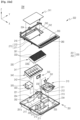
- FIG. 10a is an exploded perspective view illustrating a drying module in the shoes care device 1 according to one embodiment of the present invention.
- FIG. 10b is an exploded perspective view illustrating a partial configuration of the drying module at a part to which the damper 350 is coupled.
- the dehumidifying part 330 may be used as a means that dehumidifies air.
- the dehumidifying part 330 may be provided inside the module housing 200.
- the dehumidifying part 330 is configured to have a predetermined volume.
- the dehumidifying part 330 may be configured to be porous by itself. A plurality of pores may be formed over an entire volume of the dehumidifying part 330, and air may move by penetrating the dehumidifying part 330 through such pores.
- the dehumidifying part 330 When the dehumidifying part 330 is composed of a combination of a plurality of dehumidifying materials, the plurality of dehumidifying materials may be fixed to each other by a separate fixing means, or may be fixed to each other by adhesion.
- the dehumidifying part 330 may be formed of dehumidifying materials, and may be configured to include the dehumidifying materials.
- the dehumidifying material 331 is configured to include a material capable of reducing humidity by absorbing moisture in the air.
- the dehumidifying material 331 may be formed of various materials or a combination of the materials within the range of absorbing or adhering the moisture in the air, and may be formed in various shapes and structures.
- the dehumidifying material 331 may be referred to as a desiccant or an adsorbent.
- the dehumidifying material 331 according to one embodiment of the present invention may be formed of a microporous material.
- the dehumidifying material 331 according to one embodiment of the present invention may include silica gel, activated carbon, activated alumina (AL2O3), diatomaceous earth, etc.
- the dehumidifying material 331 may be formed of zeolite or may be configured to include zeolite.
- the zeolite is a natural and synthetic silicate mineral in which tunnels or open channels having a size of approximately 3 to 10 angstroms (A) are regularly arranged, and may function as dehumidification by adsorbing the moisture in the air.
- the zeolite When the zeolite is heated, moisture adsorbed on the zeolite may be separated into a large amount of steam. According to the characteristics of the zeolite, the zeolite may be regenerated in a state capable of not only performing the dehumidification function to remove the moisture from the air but also performing the dehumidification function by heating the zeolite and separating the moisture adsorbed to the zeolite.
- the dehumidifying part 330 may include a dehumidifying body 330a and the dehumidifying material 331.
- the dehumidifying body 330a may be formed to have a predetermined volume. In one embodiment, the dehumidifying body 330a may be formed in a substantially hexahedral shape.
- the dehumidifying body 330a may be provided with a plurality of dehumidification through holes 332 penetrated in one direction.
- a cross section of the dehumidifying through hole 332 may be formed in a circular shape, a polygonal shape, etc.
- the dehumidifying through hole 332 may have a hexagonal cross section.
- the dehumidifying through hole 332 may all have the same shape and size, or may have different shapes and sizes.
- the dehumidifying body 330a may be formed of or include materials such as synthetic resin, metal, ceramic, etc.
- the dehumidifying body 330a may be formed of a combination of fibers, and may be formed of a nonwoven fabric, etc.
- the dehumidifying material 331 may be coated on the dehumidifying body 330a.
- the dehumidifying material 331 may be coated on the outside and inside of the dehumidifying body 330a. Specifically, the dehumidifying material 331 may be coated on a surface in which the dehumidifying through hole 332 is formed.
- the zeolite When the dehumidifying body 330a is formed of a combination of fibers, the zeolite may be first coated on each fiber as the dehumidifying material 331, and the zeolite-coated fiber may be processed to form the dehumidifying body 330a and simultaneously form the dehumidifying part 330.
- the dehumidifying part 330 may be formed by coating the gelled zeolite precursor on the dehumidifying body 330a or materials constituting the dehumidifying body 330a and then performing heat treatment when the dehumidifying material 331 is formed of the zeolite.
- the coating of the dehumidifying material 331 may be performed by using various known or possible methods, and is not limited to a certain manufacturing method related to the coating of the dehumidifying material 331.
- the blowing part 310 is provided inside the connection path F10.
- a blowing fan 313 may be provided inside the blowing part 310. Since the blowing part 310 is provided in the connection path F10, air flows in the connection path F10 when the blowing part 310 is driven, and since the connection path F10 also communicates with the accommodation space 101 of the inner cabinet 100, the air flows and moves in the accommodation space 101 by driving the blowing part 310.
- connection path F10 the air may be sucked from the inner cabinet 100 into the connection path F10 by the driving of p the ventilation art 310 (a rotation of the blowing fan 313), and the air inside the connection path F10 may be ventilated.
- the blowing part 310 is provided inside the module housing 200 forming the connection path F10, and the blowing part 310 is driven to suction the air inside the inner cabinet 100 into an inlet 203.
- the air inside the connection path F10 passes through the module housing 200 constituting the connection path F10, the dry air duct 370, and a nozzle duct 810 and is then discharged back into the inner cabinet 820.
- the flow of air may be generated in the shoes care device 1 by the driving of the blowing part 310.
- Dry air may be supplied to the inside of the inner cabinet 100 by the blowing part 310.
- the heating part 320 is provided at one side of the dehumidifying part 330 and the blowing part 310 in the connection path F10.
- the heating part 320 may be provided inside the module housing 200. Based on a movement direction of the air inside the module housing 200, the module housing 200 may be arranged in an order of the blowing part 310, the heating part 320, and the dehumidifying part 330. That is, the air introduced into the outlet 203 of the module housing 200 moves along the connection path F10 by passing sequentially through the blowing part 310, the heating part 320, and the dehumidifying part 330.
- the heating part 320 is disposed inside the module housing 200 and is configured to heat the air of the module chamber 210 inside the module housing 200.
- the heating part 320 may be configured to heat the dehumidifying part 330.
- the heating part 320 may be configured to heat the dehumidifying material 331 constituting the dehumidifying part 330.
- the air heated by the heating part 320 by the driving of the blowing part 310 moves directly to the dehumidifying part 330, thus heating the dehumidifying part 330.
- the heating part 320 is disposed inside the module housing 200 adjacent to the dehumidifying part 330.
- the heating part 320 is disposed inside the module housing 200 adjacent to the dehumidifying part 330 based on a movement path of the air inside the module housing 200.
- the dehumidification by the dehumidifying material 331 or the regeneration of the dehumidifying material 331 may be achieved by selectively heating the heating part 320.
- the heating part 320 may be fixedly coupled to the module housing 200 in the module housing 200.
- the heating part 320 may be made up of various devices and structures within a range capable of heating the air inside the module housing 200 or supplying heat to the dehumidifying part 330.
- the heating part 320 may be formed of an electric heater 321.
- the heating part 320 may include the heater 321.
- the heater 321 includes a heating element, and may be configured to supply heat to the periphery while the heating element generates heat by supplied electric energy.
- the heater 321 may include a nichrome wire as the heating element.
- the heater 321 of the heating part 320 may be formed in a ring shape, and the air may move by penetrating the center and surroundings of the ring-shaped heater 321 and be simultaneously heated.
- the heater 321 of the heating part 320 may be repeatedly formed in a second module chamber 213 along the movement direction of air.
- the heater 321 of the heating part 320 may be formed in a circular ring shape or a rectangular ring shape.
- the heating part 320 may include a heater flange 322 to which the heater 321 is fixed.
- the heater flange 322 may be formed in the form of a metallic plate.
- the heater flange 322 may be formed of a combination of flat plates in the second module chamber 213 along the movement direction of air.
- the heater flange 322 has a cross section that may be formed of a plate shape or a combination of plates in the second module chamber 213 along the movement direction of air (the second direction (Y direction)).
- the heater flange 322 may include an outer flange 322a and an inner flange 322b.
- the outer flange 322a may be formed in a tubular shape along the second direction (Y direction). An interior of the outer flange 322a is provided with a space to move air along the movement direction of air (a direction parallel to the second direction (Y direction)) in the second module chamber 213.
- the inner flange 322b is fixed to the interior of the outer flange 322a.
- the inner flange 322b may include two or more plates crossing each other, and the heater 321 of the heating part 320 may be fixed to the inner flange 322b.
- the heater flange 322 may be formed in various forms that fix the heater 321 of the heating part 320 and do not interfere with a flow of air moving through the second module chamber 213.
- the blowing part 310, the heating part 320, the dehumidifying part 330, and the module housing 200 may form one set.
- the set may be provided in a plural form.
- the shoes care device 1 according to one embodiment may be provided with two sets.
- Such a set may be provided in each of the first management device 2a and the second management device 2b.
- Such a set may form a drying module DM in the shoes care device 1 according to one embodiment of the present invention.
- the drying module DM may include the module housing 200, the blowing part 310, the heating part 320, and the dehumidifying part 330. Furthermore, the drying module DM is provided in each of the first management device 2a and the second management device 2b.
- a plurality of drying modules DM may be provided.
- a pair of drying modules DM may be provided.
- one of the drying modules DM may form a 'drying module A (DM1) ' as a drying module of the first management device 2a, and the other may form a 'drying module B (DM2) ' as a drying module of the second management device 2b.
- the 'drying module' described in one embodiment of the present invention may be understood to refer to each of the 'drying module A' and the 'drying module B' except as otherwise particularly limited.
- the drying module A (DM1) and the drying module B (DM2) may operate in different modes.
- the drying module A DM1 operates in a moisture absorption mode
- the drying module B DM2 may operate in a regeneration mode.
- the drying module B DM2 may operate in the moisture absorption mode.
- the 'moisture absorption mode' described in the present invention means a case in which the dehumidifying part 330 adsorbs moisture in the air, and the 'regeneration mode' means a case in which the moisture adsorbed to the dehumidifying part 330 is separated by heating the dehumidifying part 330.
- both the drying module A DM1 and the drying module B DM2 may operate in the moisture absorption mode or may operate in the regeneration mode.
- the module housing 200 may be fixedly coupled to a lower side of the inner cabinet 100.
- the module housing 200 may be detachably coupled to a lower side of the inner cabinet 100.
- the module housing 200 includes the module chamber 210 that is a space having other components accommodated inside. That is, the module chamber 210 is a space inside the module housing 200 distinguished from an external space of the module housing 200. As described above, the module housing 200 forms part of the connection path F10, and accordingly, the module chamber 210 is configured to communicate with a space outside the module housing 200. The module chamber 210 communicates with the accommodation space 101 of the inner cabinet 100.
- the module housing 200 may include a module case 201 and a module cover 202.
- the module case 201 and the module cover 202 may be formed by injection molding, respectively, and may be assembled with each other after manufacturing to form the module housing 200.
- the module case 201 is formed in the form of a container that is concave substantially downwards, and forms the module chamber 210 of the module housing 200.
- the module case 201 may be configured in the form of a container opened upwards, and includes a module opening 201a.
- an area of the module opening 201a may be larger than or equal to an area of the module chamber 210.
- the module chamber 210 may include a first module chamber 212, a second module chamber 213, and a third module chamber 214.
- the module chamber 210 may include a suction module chamber 211.
- a module partition wall 220 may be formed inside the module housing 200. Furthermore, the module partition wall 220 guides the movement of air so that air moves in a predetermined direction inside the module housing 200.
- the suction module chamber 211 is a first space where air is introduced into the module housing 200.
- the first module chamber 212 is a space in which the blowing part 310 is accommodated
- the second module chamber 213 is a space in which the heating part 320 is accommodated
- the third module chamber 214 is a space in which the dehumidifying part 330 is accommodated.
- the suction module chamber 211, the first module chamber 212, the second module chamber 213, and the third module chamber 214 may be formed at different positions in a plan view.
- the air of the module chamber 210 may be configured to move the suction module chamber 211, the first module chamber 212, the second module chamber 213, and the third module chamber 214 sequentially. That is, when the blowing part 310 is driven, air moves sequentially through the suction module chamber 211, the first module chamber 212, the second module chamber 213, and the third module chamber 214 inside the module housing 200.
- the module case 201 may include a dry air outlet 231 and a wet air outlet 232.
- the dry air outlet 231 may be formed in a hole shape opened to allow air in the third module chamber 214 to flow out.
- the dry air outlet 231 is formed adjacent to the third module chamber 214.
- the dry air outlet 231 may be formed on one edge of the module case 201. Furthermore, the dry air outlet 231 may be connected to the accommodation space 101 through the dry air duct 370 and the nozzle duct 810.
- the wet air outlet 232 may be formed in a hole shape opened to allow the air in the third module chamber 214 to flow out.
- the wet air outlet 232 is formed adjacent to the third module chamber 214.
- the wet air outlet 232 may be formed on a frame on one side of the module case 201. Furthermore, the wet air outlet 232 may be connected to the condenser 400.
- the dry air outlet 231 and the wet air outlet 232 may be formed adjacent to each other.
- the dry air outlet 231 and the wet air outlet 232 may be formed adjacent to any one vertex part of the module housing 200.
- the suction module chamber 211 is formed adjacent to the first module chamber 212, and a bottom surface of the suction module chamber 211 may be inclined downwardly toward the first module chamber 212. Accordingly, air introduced into the suction module chamber 211 may naturally move toward the first module chamber 212 by hitting the bottom surface of the suction module chamber 211 forming an inclined surface, and a condensed water introduced into the suction module chamber 211 may move along the bottom surface of the suction module chamber 211 forming the inclined surface, and may move to the first module chamber 212.
- the blowing part 310 may be assembled to the module housing 200 while being spaced apart from a bottom surface of the first module chamber 212. Furthermore, in this case, the blowing part 310 may be configured such that air may be introduced from a lower side of the first module chamber 212 to an interior of the blowing part 310 inside the first module chamber 212.
- the module case 201 may include a first condensed water discharge hole 233.
- the first condensed water discharge hole 233 is formed in a hole shape penetrating the module case 201.
- the first condensed water discharge hole 233 is formed on an edge of the module case 201 adjacent to a condenser 400 and formed to be equal to or lower than the bottom surface of the first module chamber 212, and communicates with the condenser 400.
- the first condensed water discharge hole 233 may form the lowest part, or the bottom surface of the first module chamber 212 may be formed such that a height thereof is lowered toward or at least equal to the first condensed water discharge hole 233.
- the first condensed water discharge hole 233 may be lower than the bottom surface of the first module chamber 212, and accordingly, the condensed water introduced into the first condensed water discharge hole 232 may move toward the first condensed water discharge hole 233 and flow into the condenser 400 through the first condensed water discharge hole 233.
- the air inside the condenser 400 may flow into the module housing 200 through the first condensed water discharge hole 233.
- the air introduced into the module housing 200 through the first condensed water discharge hole 233 from an interior of the condenser 400 may move along the first module chamber 212, the second module chamber 213, and the third module chamber 214 by an operation of the blowing part 310 and may be introduced again into the condenser 400 and condensed.
- the shoes care device 1 includes the condenser 400 coupled to an outer surface of the inner cabinet 100 and forming a regeneration path F20.
- the first module chamber 212 may be provided between the second module chamber 213 and the condenser 400. Since the first module chamber 212 is disposed between the second module chamber 213 and the condenser 400, a direct heat exchange between the condenser 400 and the heating part 320 is blocked, and the heat may be prevented from being transferred to the condenser 400 when the heating part 320 is heated inside the second module chamber 213.
- condensation depending on heating of air by the heater 321 of the heating part 320 and cooling of air inside the condenser 400 may be effective performed.
- the dehumidifying part 330 may be coupled to the module housing 200 while being spaced apart from a bottom surface of the third module chamber 214. Furthermore, in this case, the air inside the third module chamber 214 may move downwards through the dehumidifying part 330 from an upper side of the third module chamber 214.
- the module case 201 may include a second condensed water discharge hole 234.
- the second condensed water discharge hole 234 is formed in a hole shape penetrating the module case 201.
- the second condensed water discharge hole 234 is formed on the edge of the module case 201 adjacent to the condenser 400 and formed to be equal to or lower than the bottom surface of the third module chamber 214, and communicates with the condenser 400.
- the second condensed water discharge hole 234 may form the lowest part, or the bottom surface of the third module chamber 214 may be formed such that a height thereof is lowered toward or at least equal to the second condensed water discharge hole 234.
- the second condensed water discharge hole 234 may be formed adjacent to the wet air outlet 232.
- the second condensed water discharge hole 234 may be lower than the bottom surface of the third module chamber 214, and accordingly, condensed water introduced into the third module chamber 214 may move toward the second condensed water discharge hole 234, and may flow into the condenser 400 through the second condensed water discharge hole 234.
- the second condensed water discharge hole 234 is a hole in which the module housing 200 and the condenser 400 communicate with each other, the air inside the condenser 400 may flow into the module housing 200 through the second condensed water discharge hole 234. In this way, the air introduced from the interior of the condenser 400 into the module housing 200 through the second condensed water discharge hole 234 moves directly to the wet air outlet 232 by the driving of the blowing part 310, and may be introduced again into the condenser 400 and condensed.
- the module housing 200 may include the module cover 202.
- the module cover 202 is coupled to the module case 201 while shielding the module opening 201a from an upper side of the module case 201.
- the module cover 202 may be detachably coupled to the module case 201.
- a plurality of locking projections 292 may protrude from one of the module cover 202 and the module case 201, and a plurality of locking grooves 291 into which the locking projections 292 are inserted and locked may be formed on the other.
- the locking projections 292 and locking grooves 291 are provided in a plural form, respectively, and may be spaced apart along an edge of the module housing 200 and repeatedly formed.
- the module cover 202 may shield the blowing part 310, the heating part 320, and the dehumidifying part 330 and may be coupled to the module case 201.
- the shoes care device 1 may be formed in a structure in which the dehumidifying part 330 may be detachable from the module housing 200.
- the structure of the shoes care device provides an advantageous advantage in maintaining and managing the dehumidifying part 330 and the shoes care device 1 on the whole.
- the dehumidifying part 330 may be repeatedly used by regeneration, but with the repeated use, the dehumidifying part 330 needs to be replaced.
- the shoes care device 1 may be configured to separate and replace the dehumidifying part 330.
- the module cover 202 of the module housing 200 may form a bottom surface of the inner cabinet 100.
- the module cover 202 may form a boundary surface between the inner cabinet 100 and the module housing 200.
- the module cover 202 may be formed in a substantially rectangular shape.
- the module cover 202 may be configured in substantially parallel with the horizontal direction.
- the module cover 202 may be inclined to any one side.
- an upper surface of the module cover 202 may be inclined downwardly toward the first direction (X direction) (a front side of the shoes care device 1).
- the main shelf 40 is mounted in close contact with an upper side surface of the module cover 202, and the main shelf 40 mounted on the upper side surface of the module cover 202 is also configured to be inclined when the upper side surface of the module cover 202 is inclined.
- water e.g., condensed water
- the shoes care device 1 may include a dehumidifying material cover 241.
- the dehumidifying material cover 241 forms part of the module cover 202 that is the bottom of the inner cabinet 100. Furthermore, the dehumidifying material cover 241 may be detached from the module cover 202 of the inner cabinet 100 or may be hinge-coupled to the module cover 202.
- a dehumidifying material exit 240 which is an opening of a shape and a size corresponding to the dehumidifying material cover 241 may be formed.
- the dehumidifying material cover 241 may be configured to open and close the dehumidifying material exit 240.
- the dehumidifying material cover 241 may be tightly coupled to the dehumidifying material exit 240. At least a part of the dehumidifying material cover 241 may be separated from the module cover 202.
- the dehumidifying material exit 240 of the module cover 202 may be opened while completely separating the dehumidifying material cover 241 from the module cover 202, and in another embodiment, the dehumidifying material cover 241 of the module cover 202 may be opened while rotating the dehumidifying material cover 241 around a hinge axis.
- the dehumidifying part 330 may be introduced into or withdrawn from the module housing 200 through the dehumidifying material exit 240.
- the dehumidifying material exit 240 and the dehumidifying material cover 241 may be formed in a position corresponding to the third module chamber 214 in a plan view. That is, the dehumidifying material exit 240 and the dehumidifying material cover 241 may be formed directly above the third module chamber 214.
- the shoes care device 1 according to one embodiment of the present invention may be configured such that the first module chamber 212 and the second module chamber 213 are not exposed in a plan view in a state where the dehumidifier cover 241 is opened.
- the dehumidifying material cover 241 When the dehumidifying material cover 241 is opened in the module cover 202, the third module chamber 214 disposed on a lower part of the module cover 202 is exposed through the dehumidifying material exit 240 of the module cover 202, and the dehumidifying part 330 may be settled inside the module case 201, or may be immediately withdrawn and separated from the module case 201.
- the sizes and shapes of the dehumidifying material cover 241 and the dehumidifying material exit 240 are variously provided within the range capable of withdrawing or inserting the dehumidifying part 330.
- the dehumidifying material cover 241 may be formed in a rectangular plate shape.
- the length of the dehumidifying material cover 241 in the first direction (X direction) may be equal to or longer than the length of the dehumidifying part 330, and the length of the dehumidifying material cover 241 in the second direction (Y direction) may be equal to or longer than the length of the dehumidifying part 330.
- the heating part 320 and the dehumidifying part 330 are formed at different positions in a top plane view, and when the dehumidifying material cover 241 is opened on the module cover 202 that forms the bottom surface of the inner cabinet 100, the dehumidifying part 330 disposed directly below the dehumidifying material cover 241 may be withdrawn from the module housing 200, and the dehumidifying part 330 may be easily replaced by the user.
- the blowing part 310 accommodated in the first module chamber 212 and the heating part 320 accommodated in the second module chamber 213 are not exposed. That is, since the blowing part 310 and the heating part 320 are not directly exposed to the user, safety accidents due to an unintended operation of the blowing part 310 and/or the heating part 320 can be prevented.
- the dehumidifying material cover 241 may be configured to separately shield the dehumidifying part 330.
- a space between the dehumidifying material cover 241 and the dehumidifying part 330 may form a part of the connection path F10.
- the outlet 203 forms an inlet through which the air inside the inner cabinet 100 is sucked into the module housing 200.
- the outlet 203 may form a start part of the connection path F10.
- the outlet 203 may be formed in the shape of a hole vertically penetrated from the bottom surface (the upper surface of the module cover 202) of the inner cabinet 100.
- a network such as a grid shape, a mesh shape, etc., may be formed on the outlet 203.
- the outlet 203 may be formed parallel to the second direction (Y direction). That is, the outlet 203 may be formed in a long hole shape in the module cover 202 along the second direction (Y direction).
- the outlet 203 may be formed on an edge of the module cover 202.
- the outlet 203 may be formed on the edge of the module cover 202 along the second direction (Y direction).
- the outlet 203 may be formed on a front part or a rear part of the module cover 202 based on the first direction (X direction).
- the outlet 203 may be disposed relatively close to the door 30 in the module cover 202. That is, the outlet 203 may be disposed relatively in the front of the module cover 202.
- the upper surface of the module cover 202 may be inclined downwardly toward the outlet 203. That is, a part of the module cover 202 where the outlet 203 is formed may be configured to be the lowest. Accordingly, when water is present on the module cover 202 or the main shelf 40, such water may flow along the surface of the module cover 202 by gravity and flow into the inlet 203.
- the module chamber 210 is provided inside the module housing 200, and the module chamber 210 includes a first module chamber 212, a second module chamber 213, and the third module chamber 214.
- the first module chamber 212, the second module chamber 213, and the third module chamber 214 may be formed at different positions in a plan view. That is, the blowing part 310, the heating part 320, and the dehumidifying part 330 may be disposed at different positions in the module housing 200.
- the blowing part 310, the heating part 320, and the dehumidifying part 330 which are main means for drying the air inside the inner cabinet 100 and main means for regenerating the dehumidifying part 330, are disposed together in the module chamber 210 of the module housing 200. Accordingly, the blowing part 310, the heating part 320, and the dehumidifying part 330 are disposed at positions considerably close to each other.
- the module case 201 of the module housing 200 may be integrally formed by injection molding.
- the bottom parts of the module housing 200 may be integrally formed, the bottom parts may not be assembled with each other, and no gaps may be formed in the bottom parts.
- the condensed water can be effectively prevented from leaking from the module housing 200.
- a vertical height of the module housing 200 can be minimized.
- the shoes care device 1 When moisture remains at an unintended part inside the shoes care device 1, such moisture may reproduce bacteria or cause odors. This is why there is need for countermeasures to solve the problems, and the shoes care device 1 according to one embodiment of the present invention can effectively prevent water from leaking in consideration of such problems.
- the air in the module chamber 210 may sequentially move the first module chamber 212, the second module chamber 213, and the third module chamber 214. Accordingly, since the third module chamber 214 and a drying flow path F10b may be connected in the shortest distance, which provides excellent drying efficiency by the dehumidifying part 330, and air heated by the heating part 320 moves directly to the dehumidifying part 330 to form the shoes care device 1 with excellent regeneration efficiency.
- the module housing 200 includes the suction module chamber 211, and the bottom surface of the suction module chamber 211 may be inclined downwardly toward the first module chamber 212. Accordingly, the air introduced through the outlet 203 moves naturally to the first module chamber 212 by hitting the bottom surface of the suction module chamber 211, and the condensed water introduced into the outlet 203 moves to the first module chamber 212 such that the condensed water can be easily drained.
- the shoes care device 1 may include the condenser 400, and the module case 201 may include the first condensed water discharge hole 233.
- the module case 201 may include the second condensed water discharge hole 234. Accordingly, the dehumidifying part 330 may be effectively regenerated, and condensed water inside the module housing 200 may be easily discharged to the condenser 400.
- steam generated by the steam generator 700 is supplied to the accommodation space 101 of the inner cabinet 100, and to this end, the shoes care device 1 includes a steam inlet 204.
- the steam inlet 204 forms an inlet through which steam is supplied to the accommodation space 101 of the inner cabinet 100.
- the steam inlet 204 is formed in the module housing 200.
- the steam inlet 204 may be formed in a rear part of the module housing 200 based on the first direction (X direction).
- the steam inlet 204 may be formed to vertically penetrate the module housing 200.
- the steam inlet 204 may be formed to vertically penetrate the module case 201 and the module cover 202.
- the steam inlet 204 may be formed in the center in a right-left direction at the rear part of the module housing 200.
- the steam inlet 204 may be formed on a rear edge of the module housing 200, and may be formed directly behind a position where the third module chamber 214 is formed. The third module chamber 214 and the steam inlet 204 are shielded from each other.
- the module cover 202 forms the bottom surface of the accommodation space 101, and when the module housing 200 is coupled to the inner cabinet 100, the steam inlet 204 is formed behind the bottom of the inner cabinet 100.
- the steam generator 700 and the steam valve 710 are disposed in a lower part, the distance from the steam generator 710 to the steam inlet 204 can be reduced by forming the module housing 200, and the steam inlet 204 in a rear part of the module housing 200, and an increase in the load required for the supply of steam can be prevented. Accordingly, steam may be smoothly supplied from the steam generator 700 to the steam inlet 204
- FIG. 11 is a diagram illustrating a connection relationship between components and a flow of fluid in the shoes care device 1 according to one embodiment of the present invention.
- connection path F10 forms a movement path of air connected from the outlet 203 to the nozzle 820. That is, the outlet 203 may form an inlet of the connection path F10, and the nozzle 820 may form an outlet of the connection path F10.
- the outlet 203 may be coupled to communicate with the inner cabinet 100, and the nozzle 820 may be provided inside the inner cabinet 100. Except the outlet 203 and the nozzle 820, one part of the connection path F10 may be provided inside the inner cabinet 100, and the other part may be provided outside the inner cabinet 100.
- connection path F10 The air inside the inner cabinet 100 moves to the connection path F10 through the outlet 203, and the air passing through the connection path F10 moves back into the inner cabinet 100 through the nozzle 820. As such air flow is repeated, the air circulation is performed in the shoes care device 1.
- a hole through which air is discharged is formed in the accommodation space 101 of the inner cabinet 100, and the nozzle 820 may form a last part of the connection path F10.
- the nozzle 820 is configured to be movable to various positions inside the inner cabinet 100, the shoes may be managed in various positions.
- the dehumidifying part 330 is disposed in the connection path F10.
- the air moving through the connection path F10 passes through the dehumidifying part 330, and the dehumidifying part 330 absorbs moisture from the air moving through the connection path F10 such that the air from which moisture has been removed may be supplied into the inner cabinet 100.
- connection path F10 may be divided into a conversion flow path F10a and a drying flow path F10b.
- the conversion flow path F10a and the drying flow path F10b form a movement path of air sequentially connected to each other.
- the air in the connection path F10 may sequentially move through the conversion flow path F10a and the drying flow path F10b.
- the conversion flow path F10a forms an upstream section of the connection path F10, which is connected to the outlet 203.
- the conversion flow path F10a may be a section in which the blowing part 310, the heating part 320, and the dehumidifying part 330 are disposed.
- the conversion flow path F10a may be formed by the module housing 200, and the module chamber 210 inside the module housing 200 may form the conversion flow path F10a.
- the conversion flow path F10a may be a section in which humid air moves and dries.
- the conversion flow path F10a may be a section in which air is dehumidified by the dehumidifying part 330.
- the conversion flow path F10a may be a section in which the dehumidifying part 330 (the dehumidifying material 331) are regenerated.
- the drying flow path F10b forms a downstream section of the connection path F10, which connects the conversion flow path F10a to the nozzle 820.
- a flow path formed by the drying air duct 370, the nozzle duct 810, and the nozzle 820 may form the drying flow path F10b.
- the drying passage F10b may be a section in which dry air with moisture removed therefrom moves.
- the drying flow path F10b When the drying module DM operates in the moisture absorption mode, the drying flow path F10b communicates with the conversion flow path F10a, and when the drying module DM operates in the regeneration mode, the drying flow path F10b and the conversion flow path F10a may not communicate with each other such that the drying flow path F10b and the conversion flow path F10a block each other.
- the dry air duct 370 may be fixedly coupled to an outer wall surface of the inner cabinet 100, and the nozzle duct 810 may be provided inside the inner cabinet 100.
- a flow path may be formed between the dry air duct 370 and the inner cabinet 100 (the inner rear plate 110), and such a flow path may form a part of the drying flow path F10b.
- a lower part of the dry air duct 370 communicates with the dry air outlet 231 of the module housing 200, an upper part thereof communicates with the nozzle duct 810, which connect the interior of the module housing 200 and the interior of the nozzle duct 810 for mutual communication.
- the air is dehumidified by the dehumidifying part 330 and converted into dry air, and the dry air can be resupplied to the accommodation space 101 of the inner cabinet 100 through the drying flow path F10b.
- the regeneration path F20 forms a movement path of a fluid.
- the regeneration path F20 forms a passage through which air and/or condensed water inside the shoes care device moves.
- the regeneration path F20 forms a path through which air and/or condensed water passing through the dehumidifying part 330 moves when the dehumidifying material 331 is regenerated.
- the regeneration path F20 may be entirely or partially formed of a pipe, a hose, a tube, a duct, a housing, or a combination thereof.
- the shoes care device 1 includes the regeneration path F20, and when the dehumidifying material 331 is regenerated, air passing through the dehumidifying part 330 is not ventilated to the nozzle 820 but moves through the regeneration path F20.
- the regeneration path F20 is a flow path branched from the connection path F10.
- the regeneration path F20 may be branched from the connection path F10 to form a path different from that of the drying flow path F10b of the connection path F10.
- the regeneration path F20 is connected to the sump 600.
- the regeneration path F20 may be a section that connects the conversion flow path F10a and the sump 600.
- the regeneration path F20 may be a section in which humid air separated from the dehumidifying part 330 moves.
- the condenser 400 forms a regeneration path F20. Moisture separated from the dehumidifying material 331 may be condensed after moving to the condenser 400 along with air moving along the regeneration path F20. In addition, condensed water condensed in the condenser 400 may be moved to the sump 600 through the regeneration path F20, collected from a lower part of the sump 600, and then discharged to the drain tank 70, discharged to the outside, or pressed to the steam generator 700.
- the regeneration path F20 when the drying module DM operates in the regeneration mode, the regeneration path F20 communicates with the conversion flow path F10a, and when the drying module DM operates in the moisture absorption mode, the regeneration path F20 and the conversion flow path F10 may not communicate with each other such that the regeneration path F20 and the conversion flow path F10 block each other.
- the damper 350 may be formed in the form of a damper valve.
- the damper 350 may be rotatably coupled to the module housing 200.
- the damper 350 may be coupled to the module housing 200 in a form accommodated in the module housing 200.
- the dry air outlet 231 forming an inlet of the drying flow path F10b is formed as a passage of the connection path F10, and the wet air outlet 232 forming an inlet of the regeneration path F20 is formed.
- the damper 350 controls a movement path of air passing through the dehumidifying material 331 in the module housing 200. Depending on the operation of the damper 350, the air passing through the dehumidifying material 331 may move into the inner cabinet 100 through the nozzle 820 or may move into the regeneration path F20.
- the damper 350 may be configured to open the regeneration path F20 while blocking the drying flow path F10b, or to open the drying flow path F10b while blocking the regeneration path F20.
- the damper 350 may be configured to selectively shield the dry air outlet 231 and the wet air outlet 232.
- the damper 350 may be configured to selectively seal the dry air outlet 231 and the wet air outlet 232.
- the damper 350 may selectively block one of the dry air outlet 231 and the wet air outlet 232.
- the damper 350 opens the dry air outlet 231 while blocking the wet air outlet 232, the air passing through the dehumidifying material 331 may move into the inner cabinet 100 through the nozzle 820, and when the damper 350 opens the wet air outlet 232 while blocking the dry air outlet 231, the air passing through the dehumidifying material 331 may be condensed while moving through the regeneration path F20.
- the damper 350 may be configured to be hinge-rotatable around a hinge axis 350a formed on one side.
- the hinge axis 350a of the damper 350 may be parallel to the third direction (Z direction).
- the shoes care device 1 may include a damper motor 351 configured to rotate the damper 350 around the hinge axis 350a of the damper 350.
- the damper motor 351 may be formed as an electric motor and may be configured to rotate the damper 350 bidirectionally.
- the damper 350 opens the dry air outlet 231 and seals the wet air outlet 232
- the air inside the inner cabinet 100 moves along the connection path F10 and is circulated by sequentially passing through the inlet 203, the module housing 200 (the blowing part 310 and the dehumidifying part 330, the dry air outlet 231, the dry air duct 370, the nozzle duct 810, and the nozzle 820.
- the damper 350 seals the dry air outlet 231 and opens the wet air outlet 232, the air moves along the conversion flow path F10a and the regeneration path F20 and is circulated by sequentially passing through the module housing 200 (the blowing part 310, the heating part 310, and the dehumidifying part 330), the wet air outlet 232, and the condenser 400.
- the controller 10 may control the damper motor 351 such that the damper 350 closes the dry air outlet 231 and opens the wet air outlet 232 when the heating part 320 is turned on.
- the controller 10 may control the damper motor 351 such that the damper 350 opens the dry air outlet 231 and closes the wet air outlet 232 when the heating part 320 is turned off.
- the damper 350 may open the drying flow path F10b and close the regeneration path F20 when the heating part 320 is turned off, and may close the drying flow path F10b and open the regeneration path F20 when the heating part 320 is turned on.
- the damper motor 351 may be controlled individually in each of the first management device 2a and the second management device 2b.
- the damper 350 seals the wet air outlet 232 and opens the dry air outlet 231 of the second management device 2b
- the drying module B (DM2) of the second management device 2b when the damper 350 opens the wet air outlet 232 and seals the dry air outlet 231, the air in the conversion flow path F10a of the first management device 2a may flow through the drying flow path F10b, and the air in the conversion flow path F10a of the second management device 2b may flow through the regeneration path F20.
- the drying module A (DM1) of the first management device 2a may operate in the moisture absorption mode
- the drying module B (DM2) of the second management device 2b may operate in the regeneration mode.
- the damper 350 when in the drying module A (DM1) of the first management device 2a, the damper 350 opens the wet air outlet 232 and seals the dry air outlet 231, and in the drying module B (DM2) of the second management device 2b, the damper 350 seals the wet air outlet 232 and opens the dry air outlet 231, the air in the conversion flow path F10a of the first management device 2a may flow along the regeneration path F20, and the air in the conversion flow path F10a of the second management device 2b may flow along the drying flow path F10b. Furthermore, in this case, the drying module A (DM1) of the first management device 2a may operate in the regeneration mode, and the drying module B (DM2) of the second management device 2b may operate in the moisture absorption mode.
- both the drying module A DM1 of the first management device 2a and the drying module B (DM2) of the second management device 2b when the damper 350 seals the wet air outlet 232 and opens the dry air outlet 231, both the drying module A DM1 and the drying module B (DM2) may operate in the moisture absorption mode.
- both the drying module A (DM1) of the first management device 2a and the drying module B (DM2) of the second management device 2b when the damper 350 seals the dry air outlet 231 and opens the wet air outlet 232, both the drying module A (DM1) and the drying module B (DM2) may operate in the regeneration mode.
- the first management device 2a and the second management device 2b individually include the inner cabinet 100, the connection path F10, the blowing part 310, and the dehumidifying part 330.
- the shoes care device 1 includes the steam generator 700 and the steam valve 710. Accordingly, the degree of the supply of steam, the degree of dehumidification by the dehumidifying part 330, and the flow of air circulated along the connection path F10 may be different in each of the first management device 2a and the second management device 2b, and the first management device 2a and the second management device 2b may manage shoes under different conditions.
- the first management device 2a and the second management device 2b include the module housing 200, the blowing part 310, the heating part 320, the dehumidifying part 330, and the drying flow path F10b, respectively.
- the air and condensed water moving in the first management device 2a and the air and condensed water moving in the second management device 2b move along different paths, thereby achieving accurate control intended in each of the first management device 2a and the second management device 2b.
- the first management device 2a and the second management device 2b share and use the steam generator 700, the steam generator 700 can be efficiently utilized in the shoes care device 1, and the shoes care device 1 can efficiently utilize the space.
- the dehumidifying part 330 may be regenerated in the other, and the efficient management of the shoes and efficient use of the shoes care device 1 can be achieved.
- the first management device 2a and the second management device 2b each include the regeneration path F20 and the damper 350 individually.
- the controller 10 may control the heating part 320 (the heater 321) and the damper 350 to interwork with each other.
- the controller 10 may control the damper 350 to open the drying flow path F10b and close the regeneration path F20 when the heating part 320 is turned off, and may control the damper 350 to close the drying flow path F10b and open the regeneration path F20 when the heating part 320 is turned on.
- the controller 10 may control each component of the shoes care device 1 such that air flowing into the module chamber 210 from the accommodation space 101 and passing through the dehumidifying part 330 moves along the drying flow path F10b when the heating part 320 is turned off (when the heater 321 of the heating part 320 is turned off), and the air moves along the regeneration path F20 when the heating part 320 is turned on (when the heater 321 of the heating part 320 is turned on).
- Such control may be performed individually in each of the first management device 2a and the second management device 2b. Accordingly, since the movement path of air inside the module chamber 210 is changed depending on an operation of the heating part 320, the drying of the shoes and the regeneration of the dehumidifying part 330 can be effectively achieved.
- the controller 10 may control the steam valve 710 and the heating part 320 to interwork with each other.
- the controller 10 ma control the steam valve 710 such that when the heating part 320 of the first management device 2a is turned off, the valve disk 715 closes or opens the first valve outlet 713, when the heating part 320 of the first management device 2a is turned on, the valve disk 715 closes the first valve outlet 713, when the heating part 320 of the second management device 2b is turned off, the valve disk 715 closes or opens the second valve outlet 714, and when the heating part 320 of the second management device 2b is turned on, the valve disk 715 closes the second valve outlet 714.
- the supply of steam to the accommodation space 101 of the inner cabinet 100 and the operation of the heating part 320 inside the module housing 200 may interwork with each other to effectively perform the drying of the shoes and the regeneration of the dehumidifying part 330.
- the shoes care device 1 may include a first sensor 361 and a second sensor 362 (see FIG. 9 ).
- the first sensor 361 may be installed in the second module chamber 213 of the module housing 200, and the second sensor 362 may be installed in the third module chamber 214 of the module housing 200.
- the first sensor 361 may be configured to measure the temperature and/or humidity of the second module chamber 213, and the second sensor 362 may measure the temperature and/or humidity of the third module chamber 214.
- the first sensor 361 measures the temperature and/or humidity of air before passing through the dehumidifying part 330
- the second sensor 362 measures the temperature and/or humidity of air after passing through the dehumidifying part 330.
- the controller 10 may compare the temperature and/or humidity of the second module chamber 213 measured by the first sensor 361 with the temperature and/or humidity of the third module chamber 214 measured by the second sensor 362 to recognize a state and a change of the temperature and/or humidity inside the module housing, and may also check an operation state of the drying module DM.
- the controller 10 may recognize the temperature and humidity of the second module chamber 213 measured by the first sensor 361, and the temperature and humidity of the third module chamber 214 measured by the second sensor 362 to recognize a change in the humidity inside the module housing 200. Accordingly, the degree of dehumidification by the dehumidifying part 330 may be checked, and the degree of regeneration of the dehumidifying part 330 may be checked.
- the controller 10 may control the drying module DM to stop operating in the moisture absorption mode and operate in the regeneration mode if a humidity change amount of the second module chamber 213 recognized by the first sensor 361 and a humidity change amount of the third module chamber 214 recognized by the second sensor 362 is less than or equal to a reference value.
- the controller 10 may control the drying module DM to stop operating in the regeneration mode if the humidity change amount of the second module chamber 213 recognized by the first sensor 361 and the humidity change amount of the third module chamber 214 recognized by the second sensor 362 is less than or equal to the reference value.
- the shoes care device 1 further includes a third sensor 363 capable of measuring the amount of moisture adsorbed to the dehumidifying material 331, and the controller 10 may control the drying module DM to operate the regeneration mode until the amount of moisture measured by the third sensor 363 is less than or equal to a set value.
- the controller 10 may control all the heating parts 320 to operate until the amount of moisture measured by the third sensor 363 is less than or equal to the set value.
- the third sensor 363 may include a moisture sensor installed adjacent to the dehumidifying material 331 to measure the amount of moisture adsorbed to the dehumidifying material 331, and the type and number thereof may vary as necessary.
- the shoes care device 1 when the moisture adsorbed on the dehumidifying material 331 is sensed to exceed the reference value, the shoes care device 1 according to one embodiment of the present invention first regenerates all dehumidifying materials 331 until the moisture is less than or equal to the reference value. Accordingly, the dehumidifying material 331 can maintain an appropriate state for dehumidification all the times even when the shoes care device 1 operates to refresh the shoes.
- FIG. 12a is an exploded perspective view illustrating the dehumidifying part 330 and the dehumidifying material housing 340 according to one embodiment of the present invention.
- FIG. 12b is a view illustrating an inner state of the dehumidifying material housing 340 with the dehumidifying part 330.
- FIG. 13 is a bottom perspective view illustrating a module cover 202 according to one embodiment of the present invention.
- FIG. 14a is a cross-sectional view illustrating a part of a third module chamber 214 of the module housing 200 in the shoes care device 1 according to the present invention.
- FIG. 14b is a cross-sectional view illustrating the dehumidifying part 330 in the shoes care device 1 according to the present invention.
- the dehumidifying part 330 may be configured to have a predetermined thickness and length. In one embodiment, as described above, the dehumidifying part 330 may be configured to have a substantially hexahedral shape.
- the dehumidifying part 330 may have a predetermined length, width, and thickness.
- Each of a length ZD1 and a width ZD2 of the dehumidifying part 330 may be formed longer than a thickness ZD3 of the dehumidifying part 330.
- the length ZD1 and the width ZD2 of the dehumidifying part 330 be made more than twice the thickness ZD3 of the dehumidifying part 330.
- the length ZD1 of the dehumidifying part 330 may be formed longer than the width ZD2 of the dehumidifying part 330.
- the dehumidifying part 330 includes an upper surface 333 and a lower surface 334 facing each other.
- the upper surface 333 of the dehumidifying part 330 and the lower surface 334 of the dehumidifying part 330 are opposite surfaces facing each other in the thickness direction of the dehumidifying part 330.
- the upper surface 333 of the dehumidifying body 330a is the same as the upper surface 333 of the dehumidifying part 330
- the lower surface 334 of the dehumidifying body 330a is the same as the lower surface 334 of the dehumidifying part 330.
- the upper surface 333 of the dehumidifying body 330a is provided on the upper side of the dehumidifying body 330a, and the lower surface 334 of the dehumidifying body 330a is provided on the lower side of the dehumidifying body 330a.
- the dehumidifying part 330 is provided with the plurality of dehumidification through holes 332.
- the dehumidifying through hole 332 may be configured to penetrate the dehumidifying part 330 in a direction in which the upper surface 333 and the lower surface 334 of the dehumidifying part 330 are connected to each other.
- the dehumidifying through-holes 332 may be provided through the dehumidifying body 330a in a direction (thickness direction) interconnecting the upper surface 333 and the lower surface 334 of the dehumidification body 330a.
- the dehumidifying part 330 is obtained by coating pulp material fabric with a zeolite component (containing silicon dioxide, titanium dioxide, and the like as main components).
- a zeolite component containing silicon dioxide, titanium dioxide, and the like as main components.
- dehumidifying through-holes 332 of a honeycomb structure are provided in the pulp material fabric, and the diameter of each dehumidifying through-hole 332 of the honeycomb structure may be about 2 mm (each dehumidifying through-hole 332 may have various shapes such as triangles, squares, and hexagons).
- the dehumidifying part 330 which is made of a pulp material, has excellent price competitiveness compared to those made of a ceramic material (ceramic materials are generally four times more expensive than pulp materials).
- the dehumidifying is made of granular zeolite
- a container for accommodating the zeolite is necessary.
- flow path resistance increases and air volume increases.
- an increase in flow path resistance can be effectively prevented.
- the rotation speeds of the blowing fan 313 (and/or the rotations speed (RPM) of the motor rotating the blowing fan 313) to generate a flow of air passing through the dehumidifying part (zeolite) during drying and during regeneration may be the same as each other.
- differences in air volume may occur depending on the conditions of respective flow paths.
- a regeneration path F20 through which air moves during regeneration may be narrower and longer than the drying path F10b through which air moves during drying. In this case, the air volume during regeneration will be smaller than the air volume during drying.
- the air volume passing through the dehumidifying part 330 was 0.05 CMM, and the air volume during regeneration of the dehumidifying part 330 was 0.15 CMM.
- the diameter HL1 of the dehumidifying through-holes 332 and the interval HL2 between the dehumidifying through-holes 332 may have similar or identical sizes.
- each of the diameter HL1 and the interval H2 may be about 2 mm.
- the interval between the dehumidifying through-holes 332 refers to the distance between adjacent dehumidifying through-holes 332.
- the average interval between the dehumidifying through-holes 332 may be equal to or greater than 1/2 of the maximum length of the cross-sectional area of the dehumidifying through-holes 332 and may be equal to or smaller than 3/2 of the maximum length of the cross-sectional area of the dehumidifying through-holes 332.
- the average interval between the dehumidifying through-holes 332 refers to the average value of the intervals between the dehumidifying through-holes 332.
- the maximum length of the cross-sectional area of the dehumidifying through-holes 332 is the diameter of the dehumidifying through-holes 332.
- the maximum length of the cross-sectional area of the dehumidifying through-holes 332 may be the longest length from one vertex to the opposite vortex of one of the dehumidifying through-holes 332, or may be the longest vertical length from one vertex to the opposite side of one of the dehumidifying through-holes 332.
- the diameter of the dehumidifying through-holes 332 described in an embodiment of the present disclosure may be understood to mean the maximum length of the cross-sectional area of the dehumidifying through-holes 332".
- the diameters of the dehumidifying through-holes 332 and the intervals between the dehumidifying through-holes 332 have similar sizes or the same size, the volume of the dehumidifying part made of a pulp material and the amount of dehumidifying material impregnated in the dehumidifying part can be made sufficient, and furthermore, smooth movement of air through the dehumidifying through-holes 332 can be achieved.
- the diameter HL1 of the dehumidifying through-holes 332 may be 2 mm or more, and the intervals between the dehumidifying through-holes 332 may be 2 mm or less.
- a first interval HL2 among the intervals between the dehumidifying through-holes 332 may be similar to the diameter Hl1 of the dehumidifying through-holes 332, and a second interval HL3 among the intervals between the dehumidifying through-holes 332 may be smaller than the diameter HL1 of the dehumidifying through-holes 332.
- the dehumidifying through-holes 332 are inclined downward from the upper surface 333 toward the lower surface 334.
- the upper surface 333 and the lower surface 334 of the dehumidifying body 330a may be orthogonal to the direction in which the dehumidifying through-holes 332 extend.
- the blowing part 310, the heating part 320, and the dehumidifying part 330 provided inside the module chamber 210 may be spaced apart from each other in the horizontal direction.
- the angle ⁇ 1 formed by the upper surface 333 of the dehumidifying body 330a with the horizontal plane is 10 to 40 degrees
- the angle ⁇ 2 formed by the lower surface 334 of the dehumidifying body 330a with the horizontal plane may be 10 to 40 degrees
- the angle ⁇ 3 formed by the dehumidifying through-holes 332 with the horizontal plane may be 60 to 80 degrees.
- the dehumidifying part 330 may be accommodated inside the module housing 200 while being accommodated in the dehumidifying material housing 340.
- the dehumidifying material housing 340 is formed in the form of a container capable of accommodating the dehumidifying part 330.
- a supporting wall 343 of the dehumidifying material housing 340 may be in close contact with the dehumidifying part 330. Accordingly, the dehumidifying part 330 can be prevented from being separated inside the dehumidifying material housing 340.
- the dehumidifying material housing 340 may include a support 341 and a supporting wall 343.
- the dehumidifying material housing 340 has an upper side opened and a lower side opened. However, the lower side of the dehumidifying material housing 340 is provided with a support 341 that supports the dehumidifying part 330 such that the dehumidifying part 330 does not deviate downwards.
- the support 341 supports the dehumidifying part 330 and contacts the lower surface 334 of the dehumidifying part 330 and the dehumidifying body 330a.
- the supports 341 may be disposed to cross each other in the form of a grid or a net.
- the gap (opening) between the supports 341 is formed sufficiently larger than the dehumidifying through hole 332 so as not to interfere with the flow of the air passing through the dehumidifying part 330.
- the support wall 343 extends upward from the edge of the support 341 to surround the edge of the dehumidifying part 330.
- the dehumidifying material housing 340 is open at the upper side to allow access to the dehumidifying part 330. That is, the upper side of the space surrounded by the support wall 343 in the dehumidifying material housing 340 is open, and the opening enables access to the dehumidifying part 330.
- the dehumidifying part 330 when the dehumidifying part 330 is disposed inside the module housing 200, the dehumidifying part 330 may be disposed so that the upper surface 333 and the lower surface 334 are inclined without being parallel to the horizontal direction.
- the dehumidifying part 330 may include a dehumidifying edge 335.
- the dehumidifying edge 335 is made of a sponge with a predetermined thickness and is coupled to the edge of the dehumidifying body 330a.
- the dehumidifying edge 335 may surround the entire edge of the dehumidifying body 330a.
- the dehumidifying edge 335 made of the sponge is elastically deformable, and is compressively deformed to come into close contact with the inside of the support wall 343 of the dehumidifying material housing 340, ensuring stable and easy coupling between the dehumidifying part 330 and the dehumidifying material housing 340.
- the dehumidifying part 330 can be easily separated from the dehumidifying material housing 340.
- the dehumidifying part 330 may have a maximum moisture content of 30 to 40% when used and a maximum moisture content of 60 to 75% when immersed in water.
- the dehumidifying part 330 when the dehumidifying part 330 includes a dehumidifying body 330a made of a pulp material impregnated with a dehumidifying material, dehumidifying through-holes 332 having a diameter and interval of 2 mm, and a dehumidifying edge 335, the dehumidifying part 330 may have a weight of about 90 g and may be made to absorb about 50g of gaseous moisture. That is, when the drying module is used in a moisture absorption mode, the dehumidifying part 330 with a weight of 90g can absorb 50g of moisture (in this case, the moisture content of the dehumidifying part 330 is about 35%). In addition, when immersed in water, as described above, the dehumidifying part 330 with a weight of 90g can absorb 200g of moisture (in this case, the moisture content of the dehumidifier 330 is about 69%).
- the dehumidifying part 330 since the dehumidifying part 330 according to an embodiment of the present disclosure is configured to absorb a sufficient amount of moisture, a drying cycle (a cycle operating in the moisture absorption mode) can be performed for a sufficient period of time.
- the dehumidifying part 330 can be manufactured by the following method.
- a pulp material fabric in which a plurality of dehumidifying through-holes are repeatedly formed over the entire area is prepared (here, the fabric may have a thickness that is equal to the thickness ZD3 of the dehumidifying body 330a and an area that is several times to dozens of times the area of the dehumidifying body 330a).
- fabric with a size of 500mm*500mm may be prepared.
- a zeolite coating solution is sprayed and impregnated into the fabric.
- the zeolite is integrated throughout the entire volume of the fabric through a drying process.
- the fabric is cut according to a predetermined standard to form the dehumidifying body 330a.
- the dehumidifying edge 335 is coupled to the edge of the dehumidifying body 330a to complete the dehumidifying part 330.
- the dehumidifying part 330 manufactured in this way can have a semi-permanent lifespan.
- the dehumidifying part 330 has no vertical directivity to be reversible upside down and to be easy to assemble.
- the dehumidifying part 330 may be disposed in the third module chamber 214 in a form inclined downwardly toward the second module chamber 213. That is, the upper surface 333 and the lower surface 334 of the dehumidifying part 330 may be disposed to be inclined downwardly toward the second module chamber 213.
- the air before penetrating the dehumidifying part 330 is disposed in an upper space of the dehumidifying part 330 in the third module chamber 214, and the air after penetrating the dehumidifying part 330 is disposed in a lower space of the dehumidifying part 330 in the third module chamber 214.
- the upper space of the dehumidifying part 330 in the third module chamber 214 is defined as 'a first flow path F10aa'
- the lower space of the dehumidifying part 330 in the third module chamber 214 is defined as 'a second flow path F10ab.
- the first flow path F10aa is a space that communicates with the accommodation space, and the second flow path F10ab forms a space spaced apart from the first flow path F10aa.
- the dehumidifying part 330 is disposed to be inclined in the third module chamber 214, the dehumidifying through hole 332 is also disposed to be inclined.
- the blowing part is configured to blow the air in the first flow path F10aa toward the second flow path F10ab, the heating part heats the air in the first flow path F10aa, and the dehumidifying part 330 is disposed between the first flow path F10aa and the second flow paths F10ab.
- the upper surface 333 of the dehumidifying body 330a faces the first flow path F10aa, and the lower surface 334 of the dehumidifying body 330a faces the second flow path F10ab.
- a cover partition wall 242 may be formed in the module cover 202.
- the cover partition wall 242 is formed in a plate shape extending downwards from the edge of the dehumidifying material exit 240.
- the cover partition wall 242 may be formed in a substantially triangular plate shape.
- the cover partition wall 242 may be configured such that a lower edge thereof is inclined downwards from the third module chamber 214 to the second module chamber 213.
- a pair of cover partition walls 242 may be provided to be spaced apart from each other in the left-right direction. The distance between the pair of cover partition walls 242 may be configured to correspond to the length of the dehumidifying part 330.
- a lower locking portion 243 may be formed in a lower edge of the cover partition wall 242 and a front edge of the cover partition wall 242 in the first direction (X direction), and an upper locking portion 342 may be formed in an upper edge of the dehumidifying material housing 340 to get settled and locked in an upper side of the lower locking portion 243. Accordingly, when the dehumidifying material housing 340 is settled in the cover partition wall 242 in a state where the dehumidifying part 330 is accommodated in the dehumidifying material housing 340, the upper locking portion 342 of the dehumidifying material housing 340 is settled and assembled in an upper side of the lower locking portion 243 of the cover partition wall 242.
- the cover partition wall 242 may block direct communication between the first flow path F10aa and the second flow path F10ab while the lower edge thereof is in close contact with the upper edge of the dehumidifying part 330.
- the air in the first flow path F10aa may pass through the dehumidifying part 330 over the entire area of the dehumidifying part 330 and move to the second flow path F10ab.
- a plurality of dehumidifying through holes 332 penetrating the dehumidifying part 330 in the thickness direction may be formed in the dehumidifying part 330, thereby increasing the contact area between the air passing through the third module chamber 214 and the dehumidifying material 331.
- the dehumidifying part 330 is not disposed parallel to the horizontal direction and is inclined downwardly toward the second module chamber 213. Comparing this with the case where the dehumidifying part 330 is disposed horizontally, the size of the upper surface of the dehumidifying part 330 may be formed larger, and the entire volume of the dehumidifying part 330 may be increased. Accordingly, the amount of dehumidification of air by the dehumidifying part 330 may be increased.
- the direction from the first flow path F10aa to the second flow path F10ab through the dehumidifying part 330 is configured not to be vertical but to be inclined.
- a rapid change in the direction of air in a path through which the air moves to the second module chamber 213, the first flow path F10aa, and the second flow path F10ab can be reduced to achieve a smooth movement of air.
- the natural movement of air moving through the dehumidifying part 330 can be achieved, and an unnecessary flow path resistance can be minimized in the third module chamber 214.
- the dehumidifying part 330 since the dehumidifying part 330 is disposed to be inclined, when air enters the dehumidifying through-holes 332 from the first flow path F10aa, the movement direction of air changes, and when air advances from the dehumidifying through-holes 332 to the second flow path F10ab, the movement direction of air changes. Accordingly, the air moving through the dehumidifying part 330 does not simply pass through the dehumidifying through-holes 332, but is capable of sufficiently penetrating into the inside of the dehumidifying body 330a made of a pulp material from the dehumidifying through-holes 332. As a result, the moisture content of the dehumidifying part can be increased, and regeneration of the dehumidifying part can be effectively achieved.
- moisture may enter or occur in the third module chamber 214.
- the bottom surface of the dehumidifying part 330 may be naturally separated from the bottom of the third module chamber 214, and the air inside the third module chamber 214 may move downwards through the dehumidifying part 330 from the upper side of the third module chamber 214. Accordingly, the small droplets or the condensed water can move along the bottom surface of the third module chamber 214 without remaining or seeping into the dehumidifying part 330, and can be easily discharged toward the condenser 400.
- the dehumidifying part 330 may have a constant cross-section along the second direction (Y direction).
- the dehumidifying part 330 may be formed in a form where the thickness thereof is deformed along the second direction (Y direction).
- the first module chamber 212 and the second module chamber 213 are formed in front of the third module chamber 214 with respect to the first direction (X direction). That is, when the longitudinal direction of the dehumidifying part 330 is formed along the second direction (Y direction), the first module chamber 212 or the second module chamber 213 does not interfere with securing the length of the third module chamber 214, and the blowing part 310 or the heating part 320 does not interfere with securing the length of the dehumidifying part 330. Accordingly, a total length ZD1 of the dehumidifying part 330 may be formed longer than the length of each of the blowing part 310 and the heating part 320 with respect to the second direction (Y direction).
- the length of the dehumidifying part 330 can be secured sufficiently long, the entire volume of the dehumidifying part 330 can be formed relatively large, and the dehumidifying amount per unit time of the dehumidifying part 330 can be improved.
- the length ZD1 of the dehumidifying part 330 may be longer than 1/2 of the length of each of the inner cabinet 100 and the module housing 200 with respect to the second direction (Y direction).
- the dehumidifying part 330 may be spaced apart from the bottom of the third module chamber 214 so that the air inside the third module chamber 214 moves downwards through the dehumidifying part 330 from the upper side of the third module chamber 214. Since the dehumidifying part 330 is spaced apart from the bottom of the third module chamber 214, the air inside the third module chamber 214 can smoothly pass through the dehumidifying part 330, and the condensed water generated by penetrating the dehumidifying part 330 moves along the bottom surface of the third module chamber 214 and can be discharged outside the module housing 200.
- the dehumidifying part 330 provided in the third module chamber 214 may be disposed to be inclined.
- the dehumidifying part 330 may be disposed to be inclined downwardly toward the second module chamber 213. Accordingly, when the air moves from the second module chamber 213 to the third module chamber 214, the air can easily pass through the dehumidifying part 330.
- the area or volume of the dehumidifying part 330 can be further expanded, and the dehumidifying amount per unit time of the dehumidifying part 330 can be improved.
- the module chamber 210 is provided below the accommodation space 101, and the blowing part 310, the heating part 320, and the dehumidifying part 330 provided inside the module chamber 210 are spaced apart from each other in the horizontal direction.
- the maximum temperature of the first flow path F10aa heated by the heating part 320 may be 95°C, and at this time, the regeneration temperature of the dehumidifying part 330 may be set to be 60 to 95°C.
- the dehumidifying part 330 includes a dehumidifying body 330a made of a pulp material and dehumidifying through-holes 332, the air heated in the first flow path F10aa can effectively penetrate into the entire interior of the dehumidifying body 330a, and sufficient regeneration of the dehumidifying part 330 can be achieved at a temperature in the range of 60 to 95°C.
- the regeneration of the dehumidifying part 330 is achieved at a predetermined temperature 95°C or lower, there is no need to set the temperature required for regenerating the dehumidifying part 330 high, and it is possible to prevent occurrence of problems due to temperature rise (e.g., the problem of damaging shoes).
- the dehumidifying part 330 is regenerated in a relatively low temperature range and the air does not stagnate in the first flow path F10aa, it is possible to prevent the upper side of the first flow path F10aa from being unintentionally heated.
- the shoe care device has remarkable industrial applicability in view of the fact that a smooth air flow path is ensured in the module chamber so that air is effectively dehumidified by the dehumidifying part, and the dehumidifying part is smoothly regenerated.
Landscapes
- Engineering & Computer Science (AREA)
- Mechanical Engineering (AREA)
- General Engineering & Computer Science (AREA)
- Life Sciences & Earth Sciences (AREA)
- Sustainable Development (AREA)
- Drying Of Solid Materials (AREA)
- Chemical & Material Sciences (AREA)
- Chemical Kinetics & Catalysis (AREA)
- General Chemical & Material Sciences (AREA)
Abstract
Description
- The present invention relates to a shoe care device, and more particular, to a shoe care device that includes a dehumidifier for drying shoes, wherein the dehumidifier is regenerated.
- Shoes may get wet by a wearer's sweat, external contaminants, or rain or snow. Wearing such shoes may make the wearer uncomfortable, and in the condition, germs may also breed or stink in the shoes.
- Accordingly, there is an increasing interest in a shoes care device, which removes germs and odors by performing a predetermined treatment on the shoes so that a user can comfortably wear the shoes all the times.
- A dehumidifying material may be used in a shoe care device, and the dehumidifying material may remove moisture to dry shoes.
- When designing and manufacturing a device containing a dehumidifying material such as zeolite for the care of shoes, it is should be considered how to further increase the dehumidifying efficiency of the dehumidifying material, whether the dehumidifying material can be effectively achieved, whether water vapor generated when using the shoe care device and regenerating the dehumidifying material can be effectively removed or managed, whether moisture will remain in unintended places when using the shoe care device and regenerating the dehumidifying material, whether the layout of components is appropriate in a limited space, whether the shoe care device is easy to use, and so on, and there is a need for the development of a shoe care device in which the above-mentioned points are considered extensively.
- As a patent document,
CN102131440A (published on July 20, 2011 ) discloses a dishwasher including a reversibly dehydratable sorption material to dry washed items, wherein the sorption material, which may be made of silica gel or zeolite, is a particulate solid with a particle size of 1 to 6 mm and is used while filled in a sorption container. - The dishwasher of
CN102131440A is configured to contain a sorption material in the form of particles filled in the sorption container and is capable of drying the items washed by the sorption material. However, since the sorption material particles with a particle size of 1 to 6 mm adhere to each other in the sorption container, air volume may decrease when air passes through the sorption material by a fan unit. -
CN102131440A , which is related to a dishwasher, has the main purpose of washing dishes, and may not consider the air volume used when drying the washed items as a major factor. - On the other hand, in a shoe care device, shoes or the like that are subject to care may be made of a material that absorbs water. Therefore, the inventors of the present disclosure would like to disclose a shoe care device that includes a dehumidifying material and has excellent shoe drying ability by maintaining sufficient air volume.
- It has been found that, when a dehumidifying part including granular zeolite is used in a shoe care device, problems may occur in that flow path resistance increases and a regeneration temperature is as high as 160°C. Thus, the present disclosure is to solve these problems as well as to provide a shoe care device that is capable of minimizing changes in drying and regeneration cycles by securing moisture absorption for drying.
- In this regard, the present disclosure is to provide a shoe care device that includes a dehumidifying part that can sufficiently come into contact with air while allowing smooth air flow in a flow path extending through the dehumidifying part so as to ensure smooth drying of shoes and regeneration of the dehumidifying part.
- In addition, the present disclosure is to provide a shoe care device in which the dehumidifying part is stably supported and can be easily replaced.
- Furthermore, the present disclosure is to provide a shoe care device in which, when the dehumidifier is placed below the area where shoes are placed, the drying of air by the dehumidifying part and the regeneration of the dehumidifying part are performed smoothly while minimizing the vertical height of the space where the dehumidifying part is disposed, and the temperature of the area where the shoes are placed can be prevented from rising to a predetermined temperature or higher.
- A shoe care device disclosed herein includes: an inner cabinet having an accommodation space configured to accommodate shoes; a module chamber including a first flow path that is in communication with the accommodation space, and a second flow path that is a space spaced apart from the first flow path; a blowing part configured to blow air from the first flow path toward the second flow path; a heating part configured to heat the air in the first flow path; and a dehumidifying part disposed between the first flow path and the second flow path.
- The dehumidifying part includes: a dehumidifying body made of a pulp material impregnated with a dehumidifying material and having an upper surface facing the first flow path and a lower surface facing the second flow path; and a plurality of dehumidifying through-holes provided through the dehumidifying body to allow air introduced into the upper surface to move toward the lower surface.
- The diameter of the dehumidifying through-holes and the interval between the dehumidifying through-holes may be similar in size. The diameter of the dehumidifying through-holes and the interval between the dehumidifying through-holes may be about 2 mm.
- The average interval between the dehumidifying through-holes may be 1/2 to 3/2 of the maximum length of the cross-sectional areas of the dehumidifying through-holes.
- The diameter of the dehumidifying through-holes may be 2 mm or more.
- The interval between the dehumidifying through-holes may be 2 mm or less.
- The upper surface is provided on the upper side of the dehumidifying body.
- The lower surface is provided on the lower side of the dehumidifying body.
- The dehumidifying through-holes may be inclined downward from the upper surface toward the lower surface.
- The upper surface and the lower surface may be orthogonal to the direction in which the dehumidifying through-holes extend.
- The blowing part, the heating part, the dehumidifying part provided inside the module chamber may be spaced apart from each other in the horizontal direction so as to reduce the vertical height of the module chamber.
- The angle formed by the upper surface and the lower surface with a horizontal plane may be 10 to 40 degrees.
- The angle formed by the dehumidifying through-holes with the horizontal plane may be 60 to 80 degrees.
- The module chamber may be provided below the accommodation space.
- The shoe care device may include a dehumidifying material housing provided inside the module chamber to support the dehumidifying part.
- The dehumidifying housing may include a support provided in a grid shape and in contact the lower surface; and a support wall extending upward from the edge of the support and surrounding the edge of the dehumidifying part.
- The upper side of the space surrounded by the support wall may be open to allow access to the dehumidifying part.
- The dehumidifying part may include a dehumidifying edge that is made of a sponge with a predetermined thickness and coupled to the edge of the dehumidifying body. The dehumidifying edge has an outer surface that is in close contact with the inner surface of the support wall.
- The dehumidifying part may have a maximum moisture content of 30 to 40% when used and a maximum moisture content of 60 to 75% when immersed in water.
- The maximum temperature of the first flow path heated by the heating part may be 95°C.
- The regeneration temperature of the dehumidifier may be 60 to 95°C.
- In the shoe care device according to an embodiment of the present disclosure, the dehumidifying part includes: a dehumidifying body made of a pulp material impregnated with a dehumidifying material and having an upper surface facing the first flow path and a lower surface facing the second flow path; and a plurality of dehumidifying through-holes provided through the dehumidifying body to allow air introduced into the upper surface to move toward the lower surface. The dehumidifying through-holes may be inclined downward from the upper surface toward the lower surface. According to the embodiment of the present disclosure, since an increase in the flow path provided through the dehumidifying part is prevented, sufficient contact between the dehumidifying material and air in the dehumidifying part can be made while achieving smooth air flow, smooth drying of shoes and regeneration of the dehumidifying part can be achieved in the shoe care device, and changes in the drying cycle (moisture absorption mode) and regeneration cycle (regeneration mode) can be minimized.
- In the shoe care device according to an embodiment of the present disclosure, the dehumidifying part includes a dehumidifying edge coupled to the edge of the dehumidifying body and having an outer surface that is in close contact with the support wall of the dehumidifying housing. According to the embodiment of the present disclosure, the dehumidifying part is stably supported by the dehumidifying housing, smooth air flow through the dehumidifying through-holes in the dehumidifying part is achieved, and the dehumidifying part is easily replaced.
- In the shoe care device according to an embodiment of the present disclosure, the module chamber is provided below the receiving space, and the blowing part, the heating part, and the dehumidifying part provided inside the module chamber are spaced apart from each other in the horizontal direction. The maximum temperature of the first flow path heated by the heating part may be 95°C, and the regeneration temperature of the dehumidifying part may be 60 to 95°C. Since the air in the first flow path moves through the dehumidifying through-holes, drying of the air by the dehumidifying part and regeneration of the dehumidifying part can be achieved smoothly, and unintentional heating of the upper side of the first flow path due to regeneration of the dehumidifying part in a relatively low temperature range and stagnation of the air in the first flow path can be prevented. As a result, it is possible to prevent the floor of the inner cabinet and the area where the shoes are placed (main shelf) from being excessively heated and damaging the shoes.
- According to the embodiment of the present disclosure, since air moves through the dehumidifying through-holes, a decrease in air volume inside the module chamber as well as a decrease in air volume inside the inner cabinet can be prevented when drying shoes, and smooth air flow is formed around the shoes. Therefore, it is possible to provide a shoe care device which is excellent in drying ability even when drying moist shoes.
-
-
FIG. 1a is a perspective view illustrating a shoes care device according to one embodiment of the present invention. -
FIG. 1b is a perspective view of the shoes care device ofFIG. 1a , when viewed from another direction, illustrating a state in which a door is opened. -
FIG. 2a is a perspective view illustrating a state in which a part of the door and an outer cabinet are removed from the shoes care device ofFIG. 1b . -
FIG. 2b is a perspective view illustrating a state in which the shoes care device illustrated inFIG. 2a is viewed from another direction. -
FIG. 3a is a front view illustrating a state in which a door is removed from the shoes care device illustrated inFIG. 1b .FIG. 3a illustrates shoes accommodated in an inner cabinet together.FIG. 3b is a view illustrating an inner surface of a door with a door seal. -
FIG. 4a is a cross-sectional view taken along line A-A' of the shoes care device illustrated inFIG. 3a ,FIG. 4b is a cross-sectional view taken along line B-B' of the shoes care device illustrated inFIG. 3a , andFIG. 4c is a cross-sectional view taken along line C-C' of the shoes care device illustrated inFIG. 3a .FIGS. 4a to 4c illustrate a form where a door is included in the shoes care device, and do not illustrate shoes. -
FIG. 5 is a perspective view illustrating a state in which the door, the outer cabinet, and the inner cabinet are removed from the shoes care device according to one embodiment of the present invention. -
FIG. 6 is a perspective view illustrating a part of a machine room of the shoes care device illustrated inFIG. 5 . -
FIG. 7a is a view illustrating a steam valve according to one embodiment of the present invention, and illustrating a connection relationship considering the movement of steam.FIG. 7b is an exploded perspective view illustrating the steam valve illustrated inFIG. 7a . -
FIG. 8a is a cross-sectional view taken along line D-D' of the shoes care device illustrated inFIG. 3a . -
FIG. 8b is a view illustrating a state in which a main shelf is removed from the shoes care device illustrated inFIG. 8a . -
FIG. 9 is a cross-sectional view taken along line E-E' of the shoes care device illustrated inFIG. 3a . -
FIG. 10a is an exploded perspective view illustrating a drying module in the shoes care device according to one embodiment of the present invention.FIG. 10b is an exploded perspective view illustrating a partial configuration of the drying module at a part to which a damper is coupled. -
FIG. 11 is a diagram illustrating a connection relationship between components and a flow of fluid in the shoes care device according to one embodiment of the present invention. -
FIG. 12a is an exploded perspective view illustrating the dehumidifying part and the dehumidifying material housing according to one embodiment of the present invention. -
FIG. 12b is a view illustrating an inner state of the dehumidifying material housing with the dehumidifying part. -
FIG. 13 is a bottom perspective view illustrating a module cover according to one embodiment of the present invention. -
FIG. 14a is a cross-sectional view illustrating a part of a third module chamber of the module housing in the shoes care device according to the present invention. -
FIG. 14b is a cross-sectional view illustrating the dehumidifying part in the shoes care device according to the present invention. - Hereinafter, in order to describe the present disclosure in more detail, embodiments according to the present disclosure will be described in more detail with reference to the accompanying drawings. Like reference numerals indicate like elements throughout the detailed description.
- The present disclosure presents specifications of a dehumidifying material (zeolite) that ensures smooth air flow in a connection path in order to achieve smooth drying and regeneration of objects to be cared for (products made of cloth, fiber, leather, or the like, which may include shoes (including leather shoes, sneakers, and the like), bags, clothing, hats, dolls, and the like). In particular, in order to achieve smooth drying and regeneration of shoes, specifications of a dehumidifying material (zeolite) that ensures smooth air flow in a connection path are presented.
- The present disclosure constitutes a drying cycle and a regeneration cycle that can ensure a smooth air flow path.
- The present disclosure is to reduce flow path resistance by reflecting the honeycomb structure of zeolite as a dehumidifying material.
- The present disclosure is to ensure sufficient moisture absorption for drying.
- The present disclosure is to minimize drying time by minimizing changes in drying cycle and regeneration cycle.
- The present disclosure is to minimize shoe damage by lowering a regeneration temperature.
- First, a
management device 1 according to an embodiment of the present disclosure will be described, and zeolite as a dehumidifying material will be described. - A
care device 1 of the present invention is commenced. Thecare device 1 may be configured to care the item so that the item becomes clean while the item is accommodated therein or a physical/chemical state of the item accommodated is improved. - A first direction (X direction), a second direction (Y direction), and a third direction (Z direction) described in one embodiment of the present invention may be directions orthogonal to each other.
- Each of the first direction (X direction) and the second direction (Y direction) may be a direction parallel to the horizontal direction, and the third direction (Z direction) may be a direction parallel to the vertical direction. When the first direction (X direction) is parallel to a left-right direction, the second direction (Y direction) may be parallel to a front-rear direction. When the first direction (X direction) is parallel to the front-rear direction, the second direction (Y direction) may be parallel to the left-right direction.
-
FIG. 1a is a perspective view illustrating ashoes care device 1 according to one embodiment of the present invention. -
FIG. 1b is a perspective view of the shoes care device ofFIG. 1a , when viewed from another direction, illustrating a state in which a door is opened. -
FIG. 2a is a perspective view illustrating a state in which a part of the door and an outer cabinet are removed from the shoes care device ofFIG. 1b . -
FIG. 2b is a perspective view illustrating a state in which the shoes care device illustrated inFIG. 2a is viewed from another direction. - A shoes care
device 1 according to one embodiment of the present invention may include anouter cabinet 20, adoor 30, aninner cabinet 100, and amachine room 50. The shoes caredevice 1 may include amain frame 5. - The
outer cabinet 20 and thedoor 30 may form an overall appearance of the shoes caredevice 1. The outside of the shoes caredevice 1 may be formed in a hexahedral shape. That is, while theouter cabinet 20 and thedoor 30 are coupled to each other and thedoor 30 is closed, the appearance of the shoes caredevice 1 may be formed in a hexahedral shape. However, the shoes caredevice 1 according to one embodiment of the present invention is not limited to such a shape and may have various three-dimensional shapes. - When the
door 30 forms the front of the shoes caredevice 1, theouter cabinet 20 may form an upper side surface, a left-side surface, a right-side surface, a rear surface, and bottom surfaces of the shoes caredevice 1. - The
main frame 5 may form an overall framework of the shoes caredevice 1. Themain frame 5 may have a hexahedral structure. - The
outer cabinet 20 may be detachably fixed to themain frame 5. - The
outer cabinet 20 may include an outerrear plate 21, a firstouter side plate 22, and a secondouter side plate 23. - The
outer back plate 21, the firstouter side plate 22, and the secondouter side plate 23 may be formed integrally with each other, or theouter back plate 21, the firstouter side plate 22, and the secondouter side plate 23 may be individually formed. - The outer
rear plate 21 forms a vertically erected wall surface. The outerrear plate 21 may form a surface orthogonal to the first direction (X direction). The outerrear plate 21 may form a rear wall surface in the first direction (X direction) on theouter cabinet 20. The outerrear plate 21 may form a rear surface in the first direction (X direction) in the shoes caredevice 1. The outerrear plate 21 may form an entire outer rear surface of the shoes caredevice 1. - The first
outer side plate 22 and the secondouter side plate 23 form vertically erected wall surfaces, respectively, and form opposing wall surfaces facing each other. - The first
outer side plate 22 is disposed at any one side with respect to a reference plane RP that is parallel to the first direction (X direction) as a horizontal direction and is a vertical plane. The secondouter side plate 23 is disposed on the opposite side of the firstouter side plate 22 with respect to the reference plane RP. The firstouter side plate 22 may form a left wall surface of theouter cabinet 20, and the secondouter side plate 23 may form a right wall surface of theouter cabinet 20. - The
outer cabinet 20 may be disposed outside theinner cabinet 100 and themachine room 50 to form an outer wall surface of themachine room 50. When a separate cabinet for themachine room 50 is not provided in the shoes caredevice 1, theouter cabinet 20 may form a wall separating themachine room 50 from the outside. - The
door 30 is configured to open and close the inside of the shoes caredevice 1. Thedoor 30 may form any one surface of the shoes caredevice 1. Thedoor 30 may form a left side or a right side of the shoes caredevice 1, or may form a front side of the shoes caredevice 1. - In the shoes care
device 1, thedoor 30 may be hinge-coupled. - In one embodiment, the
door 30 may be hinge-coupled to themain frame 5. In another embodiment, thedoor 30 may be hinge-coupled to theouter cabinet 20, and in another embodiment, thedoor 30 may be hinge-coupled to theinner cabinet 100 and/or themachine room 50. - A
hinge rotation axis 31 of thedoor 30 may be formed in the vertical direction. That is, in the shoes caredevice 1, thedoor 30 may be configured to be rotatable bidirectionally around arotation axis 31 in the vertical direction. - In one embodiment, the shoes care
device 1 may include onedoor 30. In another embodiment, the shoes caredevice 1 may include two or more doors. - When two doors are provided in the shoes care
device 1, each door may be individually rotated around each rotation axis. - The first direction (X direction) described in one embodiment of the present invention may be parallel to or substantially parallel to the horizontal direction.
- In one embodiment, the first direction (X direction) may be a direction from the rear of the shoes care
device 1 to the front. - Hereinafter, except for a particularly limited case, it will be described that the
door 30 is formed in a front side of the shoes caredevice 1. That is, a surface on which thedoor 30 is formed in the shoes caredevice 1 is described as a front surface of the shoes caredevice 1. - Furthermore, hereinafter, except for a particularly limited case, it will be described that the first direction (X direction) is parallel to the front-rear direction, the second direction (Y direction) is parallel to the left-right direction, and the third direction (Z direction) is parallel to the vertical direction.
- The
inner cabinet 100 and themachine room 50 may be provided inside theouter cabinet 20. - The
inner cabinet 100 may be formed in a box shape, and a predetermined space may be formed therein. The space inside theinner cabinet 100 forms anaccommodation space 101, and shoes S may be accommodated in theaccommodation space 101. - A plurality of shoes S may be disposed together in the
accommodation space 101 of oneinner cabinet 100. - The
inner cabinet 100 may be fixed to themain frame 5. - The
inner cabinet 100 has a predetermined size along the first direction (X direction), the second direction (Y direction), and the third direction (Z direction). - The
inner cabinet 100 is formed in the shape of a box opened to any one side. Theinner cabinet 100 may be formed in a form opened to the front side of the shoes caredevice 1. Theinner cabinet 100 may be configured to include amain opening 140. Themain opening 140 may be provided to open the front side of theinner cabinet 100 in the first direction (X direction). The shoes may be disposed inside theinner cabinet 100 or withdrawn from theinner cabinet 100 through themain opening 140. - The
main opening 140 of theinner cabinet 100 may be closed or opened by thedoor 30. - The
inner cabinet 100 may include an innerrear plate 110, a firstinner side plate 120, a secondinner side plate 130, and an innerupper plate 115. - The inner
rear plate 110, the firstinner side plate 120, the secondinner side plate 130, and the innerupper plate 115 may be formed integrally with each other. Theinner cabinet 100 may be made of a single material and be formed by injection molding. - The inner
rear plate 110 forms a vertically erected wall surface. The innerrear plate 110 may form a surface orthogonal to the first direction (X direction). The innerrear plate 110 may form a rear wall surface of theinner cabinet 100 in the first direction (X direction). The innerrear plate 110 may be formed parallel to the outerrear plate 21. - The first
inner side plate 120 and the secondinner side plate 130 form vertically erected wall surfaces, respectively, and form opposing wall surfaces facing each other. - The first
inner side plate 120 is dispose on either side with respect to the reference plane RP that is parallel to the first direction (X direction) as the horizontal direction and is a vertical surface. The secondinner side plate 130 is disposed on the opposite side of the firstinner side plate 120 with respect to the reference plane RP. The firstinner side plate 120 forms a left wall surface of theinner cabinet 100, and the secondinner side plate 130 forms a right wall surface of theinner cabinet 100. - The first
inner side plate 120 may be formed parallel to the firstouter side plate 22, and the secondinner side plate 130 may be formed parallel to the secondouter side plate 23. - In one embodiment of the present invention, the
inner cabinet 100 may have the form where a lower part thereof is opened. Accordingly, theinner cabinet 100 includes a lower opening 150 formed by opening the lower part thereof. When theinner cabinet 100 is formed in a hexahedral shape on the whole, the lower opening 150 may be formed large to form all or most of a lower surface of theinner cabinet 100. - However, the shoes care
device 1 according to one embodiment of the present invention is not used in a state in which an entire lower part of theinner cabinet 100 is opened, but is used in a state in which theinner cabinet 100 and amodule housing 200 are coupled to each other so that the lower opening 150 of theinner cabinet 100 is shielded by themodule housing 200. That is, the shoes caredevice 1 is used so that an upper surface of themodule housing 200 forms a bottom surface of theaccommodation space 101 of theinner cabinet 100. A further explanation thereof will be described below. - A
main shelf 40 may be provided in the inside 101 of theinner cabinet 100. Themain shelf 40 may be formed such that the shoes S are settled on an upper surface thereof. - The
main shelf 40 may be formed in the form of a plate with a predetermined area, or may be formed in the form of a grill where multiple bars are spaced apart from each other. - One
main shelf 40 may be provided, or a plurality ofmain shelves 40 may be provided. - The
main shelf 40 may have a substantially flat plate shape and be disposed on a bottom surface of theinner cabinet 100. Themain shelf 40 is settled on an upper side of amodule cover 202 of theinner cabinet 100. Themain shelf 40 may be disposed on the upper side of themodule cover 202 of theinner cabinet 100 in a stacked form. - The
main shelf 40 is detachable from theinner cabinet 100, and when themain shelf 40 is withdrawn from theinner cabinet 100, the upper surface of themodule housing 200 is exposed. - The
main shelf 40 may have a rectangular shape when viewed in a plan view. The size of themain shelf 40 may be a size corresponding to the bottom of theaccommodation space 101 of theinner cabinet 100. That is, when themain shelf 40 is disposed inside theinner cabinet 100, themain shelf 40 may form all or most of the bottom of theaccommodation space 101 of theinner cabinet 100. - In one embodiment, the
machine room 50 may be provided in a lower side of theinner cabinet 100. In themachine room 50, some of the components that constitutes the shoes caredevice 1 may be accommodated, and, in this case, the components that are accommodated in themachine room 50 may be fixed to amain frame 5 or to theinner cabinet 100 or theouter cabinet 20. -
FIG. 3a is a front view illustrating a state in which a door is removed from the shoes care device illustrated inFIG. 1b .FIG. 3a illustrates shoes accommodated in an inner cabinet together.FIG. 3b is a view illustrating an inner surface of adoor 30 withdoor seals -
FIG. 4a is a cross-sectional view taken along line A-A' of the shoes care device illustrated inFIG. 3a ,FIG. 4b is a cross-sectional view taken along line B-B' of the shoes care device illustrated inFIG. 3a , andFIG. 4c is a cross-sectional view taken along line C-C' of the shoes care device illustrated inFIG. 3a .FIGS. 4a to 4c illustrate a form where a door is included in the shoes care device, and do not illustrate shoes. - The shoes care
device 1 according to one embodiment of the present invention includesmanagement devices device 1, a plurality ofmanagement devices device 1 may include afirst management device 2a and asecond management device 2b. That is, the shoes caredevice 1 may include twoseparate management devices - The 'management device' described in the present invention may refer to a '
first management device 2a' and a 'second management device 2b', respectively, except for a particularly limited case. - The
management devices inner cabinet 100. - In one embodiment of the present invention, since the
inner cabinet 100 of thefirst management device 2a and theinner cabinet 100 of thesecond management device 2b may be distinguished from each other, theinner cabinet 100a of thefirst management device 2a may refer to a firstinner cabinet 100a, andinner cabinet 100a of thesecond management device 100b may refer to a secondinner cabinet 100b. - It may be understood that the 'inner cabinet 100' described in one embodiment of the present invention refers to each of the 'first
inner cabinet 100a' and the 'secondinner cabinet 100b', except for a particularly limited case. - When the
door 30 is closed in the shoes caredevice 1, thedoor 30 closes themain opening 140 of thefirst management device 2a and also closes themain opening 140 of thesecond management device 2b. That is, thedoor 30 may simultaneously seal theaccommodation space 101 of theinner cabinet 100 of thefirst management device 2a and theaccommodation space 101 of theinner cabinet 100 of thesecond management device 2b. In this case, theaccommodation space 101 of theinner cabinet 100 of thefirst management device 2a and theaccommodation space 101 of theinner cabinet 100 of thesecond management device 2b may be configured such that they do not communicate with each other. - As described above, in one embodiment of the present invention, the
accommodation space 101 of theinner cabinet 100 of thefirst management device 2a and theaccommodation space 101 of theinner cabinet 100 of thesecond management device 2b may form independent spaces, and may form blocked spaces (not communicating with each other). Accordingly, the temperature and humidity of theaccommodation space 101 of thefirst management device 2a and the temperature and humidity of theaccommodation space 101 of thesecond management device 2b may be controlled differently from each other. - The shoes care
device 1 according to the embodiment of the present invention may simultaneously care two or more different shoes (a first shoe, a second shoe, etc.). Any one of the first shoe and the second shoe may be accommodated and cared in theinner cabinet 100 of thefirst management device 2a, and the other one may be accommodated and cared in theinner cabinet 100 of thesecond management device 2b. The firs shoe and the second shoe may be made of different materials, or configured to be in different states or to have different features. In this case, the first shoe and the second shoe need to be care in different schemes and/or different conditions. - When it is preferable to care the first shoe by using the steam, it may be preferable to care the second shoe without providing the steam. In this case, in the
shoe care device 1, the steam may be supplied to theaccommodation space 101 of theinner cabinet 100 of thefirst management device 2a, which accommodates the first shoe, and not supplied to theaccommodation space 101 of theinner cabinet 100 of thesecond management device 2b, which accommodates the second shoe. - When it is preferable to care the first shoe by using a relatively large amount of steam, it may be preferable to care the second shoe by using a relatively small amount of steam. In this case, in the
shoe care device 1, the relatively large amount of steam may be supplied to theaccommodation space 101 of theinner cabinet 100 of thefirst management device 2a, which accommodates the first shoe, and the relatively small amount of steam may be supplied to theaccommodation space 101 of theinner cabinet 100 of thesecond management device 2b, which accommodates the second shoe. - In an embodiment, when the first shoe is a sports shoe, the second shoe may be a shoe (a leather shoe).
- In the embodiment of the present invention, the
door 30 may close theaccommodation space 101 of thefirst management device 2a and theaccommodation space 101 of thesecond management device 2b not to be in communication with each other, and as a result, the movement of the steam may be interrupted between theinner cabinet 100 of thefirst management device 2a and theinner cabinet 100 of thesecond management device 2b. As a result, in theshoe care device 1 according to the embodiment of the present invention, a shoe (e.g., a first shoe) of which processing by the steam is required and a shoe (e.g., a second shoe) of which processing by the steam should be prevented can be simultaneously effectively cared. - In order to stably seal the
main opening 140 of theinner cabinet 100, theshoe care device 1 may be configured to include adoor seal 185. The door seal 185may be made of an elastically transformable material such as rubber. Thedoor seal 185 has a rectangular shape as a whole to be coupled to the inner surface of thedoor 30. When thedoor 30 is closed, thedoor seal 185 may be close attached along a border of themain opening 140 of theinner cabinet 100. Thedoor seal 185 may be closely attached to afront frame 180 of theinner cabinet 100. In theshoe care device 1, twodoor seals 185 may be provided, and onedoor seal 185a (first door seal) among the door seals 185 may be closely attached to the border of themain opening 140 of theinner cabinet 100 of thefirst management device 2a, and the other onedoor seal 185b (second seal) may be closely attached to the border of themain opening 140 of theinner cabinet 100 of thesecond management device 2b. - In the
shoe care device 1 according to an embodiment of the present invention, themain opening 140 of theinner cabinet 100 of thefirst management device 2a and themain opening 140 of theinner cabinet 100 of thesecond management device 2b may be simultaneously opened/closed. As a result, a plurality ofinner cabinets 100 may be easily opened/closed. - Further, according to the embodiment of the present invention, the plurality of
inner cabinets 100 is opened/closed by onedoor 30, and as a result, generation of a gap depending on provision of a plurality of doors (a gap between the doors), a step between the doors, interference, etc. may be fundamentally prevented and since an entire front surface of the shoes caredevice 1 may be formed by onedoor 30, a clean and beautiful external appearance may be formed. - In the embodiment of the present invention, the
first door seal 185a and thesecond door seal 185b are jointly coupled to the inner surface of onedoor 30, and as a result, a spacing distance SD between thefirst door seal 185a and thesecond door seal 185b may be formed to be comparatively narrow, and as a result, there is an effect that theaccommodation space 101 of thefirst management device 2a and theaccommodation space 101 of thesecond management device 2b may be formed to be wider.(seeFig. 4a ) - Unlike this, when each of the door (first door) of opening/closing the
accommodation space 101 of thefirst management device 2a and the door (second door) of opening/closing theaccommodation space 101 of thesecond management device 2b is individually provided, it is difficult to couple the door seal to a border end of each door in manufacturing, the SD between the first door seal and the second door seal is relatively widened, and consequently, the volume of each accommodation space is narrowed. - In the embodiment of the present invention, the
first door seal 185a and thesecond door seal 185b are jointly coupled to the inner surface of onedoor 30, and as a result, each of theaccommodation space 101 of thefirst management device 2a and theaccommodation space 101 of thesecond management device 2b may be more effectively sealed. - When the air in the
accommodation space 101 of thefirst management device 2a intends to move downward, the accommodation space is first primarily interrupted by thefirst door seal 185a, and secondarily interrupted by thesecond door seal 185b. Further, when the air in theaccommodation space 101 of thefirst management device 2a intends to move upward, the accommodation space is first primarily interrupted by thesecond door seal 185b, and secondarily interrupted by thefirst door seal 185a. - The
management devices management devices part 310 and adehumidifying part 330. Themanagement devices outlet 203 and anozzle 820. - The
management devices module housing 200 forming a connection path F10. Themodule housing 200 forms all or part of the connection path F10 - The
management devices management devices heating part 320. - The
management devices - The
management devices damper 350. - The shoes care
device 1 may include asteam generator 700 and asteam valve 710. - The shoes care
device 1 may include asump 600, awater supply tank 60, and adrain tank 70. - Since all or part of the
outer cabinet 20 may be spaced apart from theinner cabinet 100, a predetermined gap may be formed between theinner cabinet 100 and theouter cabinet 20. - In a space between the
inner cabinet 100 and theouter cabinet 20, components constituting the shoes caredevice 1 may be provided, and various flow paths constituting the shoes caredevice 1 may be provided. In one embodiment of the present invention, part of the connection path F10 may be provided between theinner cabinet 100 and theouter cabinet 20, and part of the regeneration path F20 may be provided between theinner cabinet 100 and theouter cabinet 20. - A
dry air duct 370 forming the connection path F10 may be provided between the outerrear plate 21 and the innerrear plate 110. Furthermore, acondenser 400 forming the regeneration path F20 may be provided between the outerrear plate 21 and the innerrear plate 110. - The connection path F10 forms a flow path of a fluid.
- The connection path F10 forms a passage through which air and/or condensed water inside the shoes care
device 1 moves. - The
dehumidifying part 330 is disposed inside the connection path F10 and includes a dehumidifying material. Thedehumidifying part 330 may be entirely formed of the dehumidifying material, or a part thereof may be formed of the dehumidifying material. A further explanation of thedehumidifying part 330 will be described below. - According to one embodiment of the present invention, the shoes care
device 1 has an air circulation structure in which the air inside theinner cabinet 100 in which the shoes are disposed is sucked into the connection path F10 to dehumidify the air using adehumidifying material 331 and the dehumidified air may be supplied back into theinner cabinet 100. - The connection path F10 may be used as a means to achieve such an air circulation structure in the shoes care
device 1. All or part of the connection path F10 may be formed of a pipe, a hose, a tube, a duct, a housing, or a combination thereof. - The
module housing 200 according to one embodiment of the present invention forms part of the connection path F10. - The
outlet 203 is formed in themodule housing 200. Theoutlet 203 communicates with theaccommodation space 101 of theinner cabinet 100, and forms an inlet of themodule housing 200 through which the air of theaccommodation space 101 of theinner cabinet 100 is suctioned into themodule housing 200. Theoutlet 203 may be disposed below themain shelf 40. In this case, themain shelf 40 may be formed so as not to block the air in theaccommodation space 101 from being sucked into theoutlet 203. To this end, when themain shelf 40 is formed in a plate shape, a plurality ofholes 45 penetrating in the vertical direction may be formed in themain shelf 40 so as to move the air. - In the shoes care
device 1, theinner cabinet 100 and themachine room 50 may form a space separated from each other. Furthermore, themodule housing 200 that is part of themanagement devices inner cabinet 100 and themachine room 50. - The
inner cabinet 100, themodule housing 200, and themachine room 50 are provided inside the shoes caredevice 1 according to one embodiment of the present invention. - The
inner cabinet 100, themodule housing 200, and themachine room 50 may be continuously arranged from the upper side to the lower side. When the shoes caredevice 1 according to one embodiment of the present disclosure includes thefirst management device 2a and thesecond management device 2b, thefirst management device 2a may be disposed above thesecond management device 2b. That is, thefirst management device 2a, thesecond management device 2b, and themachine room 50 may be continuously arranged from the upper side to the lower side. - Since the
first management device 2a and thesecond management device 2b include theinner cabinet 100 and themodule housing 200, respectively, they may be continuously arranged in an order of theinner cabinet 100 of thefirst management device 2a, themodule housing 200 of thefirst management device 2a, theinner cabinet 100 of thesecond management device 2b, themodule housing 200 of thesecond management device 2b, themachine room 50 from the upper side to the lower side. - The
inner cabinet 100 may form a space that mainly accommodates an article (shoes S) to be managed, and themodule housing 200 and themachine room 50 may form a space that mainly accommodates components for an operation of the shoes caredevice 1. - In the shoes care
device 1 according to one embodiment of the present invention, the blowingpart 310, the dehumidifying part 330 (and the dehumidifying material 331), and theheating part 320 may be accommodated inside themodule housing 200. - In addition, the
machine room 50 may be configured to accommodate acontroller 10, thesump 600, thesteam generator 700, and thesteam valve 710 therein. Furthermore, themachine room 50 may be configured to accommodate thewater supply tank 60 and thedrain tank 70. - Among the components constituting the
management devices module housing 200 may be fixedly coupled to theinner cabinet 100 and the outside of themodule housing 200 or may be fixedly coupled to themain frame 5. - Components coupled to or accommodated in the
machine room 50 may be fixedly coupled to themachine room 50. - The
machine room 50 may include afirst wall 51. - A
first wall 51 forms one wall surface of themachine room 50. Thefirst wall 51 may be erected in the vertical direction, or may be erected in the substantially vertical direction. In one embodiment, thefirst wall 51 may form a wall surface orthogonal to or inclined with the first direction (X direction). - The
first wall 51 may form a front wall surface of themachine room 50, a left wall of themachine room 50, or a right wall of themachine room 50. - The
machine room 50 may include asecond wall 52 and athird wall 53. Thesecond wall 52 and thethird wall 53 form opposite wall surfaces facing each other in themachine room 50. Thesecond wall 52 and thethird wall 53 may be erected in the vertical direction, or may be erected in the substantially vertical direction. - When the
first wall 51 forms a front wall of themachine room 50, thesecond wall 52 may form a left wall of themachine room 50, and thethird wall 53 may form a right wall of themachine room 50. - The
first wall 51 may be formed integrally with theinner cabinet 100, and thesecond wall 52 and thethird wall 53 may be formed integrally with theouter cabinet 20, respectively. - Each of the
water supply tank 60 and thedrain tank 70 may be formed in the form of a container for accommodating water. - The
water supply tank 60 may be configured to store water supplied into the shoes caredevice 1 inside. Thewater supply tank 60 may be configured to store water supplied into thesteam generator 700 inside. - In order to supply water from the
water supply tank 60 into the shoes caredevice 1, awater pump 61 may be connected to thewater supply tank 60. Thewater supply tank 60 for moving water and thefirst water pump 61 may be connected by a pipe, a hose, etc. - The
drain tank 70 may be configured to store water discharged from the shoes caredevice 1 inside. Thedrain tank 70 may store water condensed inside the shoes caredevice 1. Thedrain tank 70 may be configured to store water drained from thesump 600. - In order to discharge water to the
drain tank 70, a water pump 71 (a second water pump) may be connected to thedrain tank 70. Thedrain pipe 70 for moving water and thesecond water pump 71 may be connected by a pipe, a hose, etc. - The
water supply tank 60 and thedrain tank 70 may be coupled to themachine room 50 to get exposed from the outside of one wall surface of themachine room 50. - The
water supply tank 60 and thedrain tank 70 may be disposed in front of themachine room 50. - The
water supply tank 60 and thedrain tank 70 may form one wall surface of themachine room 50 along with thefirst wall 51. When thefirst wall 51 forms a front surface of themachine room 50, thewater supply tank 60 and thedrain tank 70 may be exposed from a front side of themachine room 50, and may be coupled to themachine room 50 to get exposed from the outside of thefirst wall 51. - As the
water supply tank 60 and thedrain tank 70 are exposed to the outside of thefirst wall 51, a user may inject water into thewater supply tank 60 or discharge water from thedrain tank 70. - The
water supply tank 60 and thedrain tank 70 may be configured to be detachable from themachine room 50. Thewater supply tank 60 and thedrain tank 70 may be detached from thefirst wall 51. In order to facilitate the attachment and detachment of thewater supply tank 60 and thedrain tank 70, ahandle 60a of thewater supply tank 60 may be formed on an outer surface of thewater supply tank 60, and ahandle 70a of thedrain tank 70 may be formed on an outer surface of thedrain tank 70. - Each of the
water supply tank 60 and thedrain tank 70 may be configured to be separated from themachine room 50 in an outer direction of thefirst wall 51. - The
controller 10 may be configured to control operations of each component in connection with each component constituting the shoes caredevice 1. - In order to control the
controller 10, the shoes caredevice 1 may be provided with a storage medium in which an application program is stored, and thecontroller 10 may be configured to control the shoes caredevice 1 by driving an application program according to information input to the shoes caredevice 1 and information output from the shoes caredevice 1. - The
controller 10 may control thefirst management device 2a and thesecond management device 2b constituting the shoes caredevice 1 to operate individually. Thecontroller 10 may control thefirst management device 2a and thesecond management device 2b to operate in different states, and may control shoes (e.g., sneakers) in thefirst management device 2a and shoes (e.g., heels) in thesecond management device 2b to be managed under different conditions. Furthermore, thecontroller 10 may control thefirst management device 2a and thesecond management device 2b to interwork with each other. - The
door 30 may be disposed on either theinner cabinet 100 or themachine room 50 on the same side as thefirst wall 51. When thedoor 30 forms the front surface of the shoes caredevice 1, thefirst wall 51 forms the front surface of themachine room 50, and thedoor 30 is disposed directly outside thefirst wall 51. - In one embodiment of the present invention, the
door 30 may be configured to open and close theinner cabinet 100 and further expose or shield the front surface of themachine room 50. - The
door 30 may be configured to expose or shield theinner cabinet 100, thewater supply tank 60, and thedrain tank 70. - As described above, in the shoes care
device 1, thedoor 30, thewater supply tank 60, and thedrain tank 70 are formed on the same side, and when thedoor 30 is opened, thewater supply tank 60 and thedrain tank 70 may be exposed and separated from the shoes caredevice 1. - In the arrangement explained above, even if left and right sides and a rear side of the shoes care
device 1 are blocked by other goods or structures, thedoor 30 may be opened on a front side of the shoes caredevice 1, and thewater supply tank 60 and thedrain tank 70 can be separated from or coupled again to the shoes caredevice 1. - A
control panel 33 for controlling the shoes caredevice 1 is provided on an outer side of thedoor 30. Thecontrol panel 33 may be formed of a touch screen. A controller (controller 10) is provided in the inner space of thedoor 30 to control each component of the shoes caredevice 1 in connection with thecontrol panel 33. Thecontroller 10 may be provided inside themachine room 50. - As illustrated in
FIGS. 1a and1b , in one embodiment, thedoor 30 may be configured to simultaneously expose or shield theinner cabinet 100 and themachine room 50. - In another embodiment, the
door 30 may be configured to open and close only theinner cabinet 100. In this case, themachine room 50 may not be shielded by thedoor 30. Furthermore, in this case, the shoes caredevice 1 according to one embodiment of the present invention may be further provided with a dedicated door of themachine room 50 to open and close themachine room 50 separately from thedoor 30. -
FIG. 5 is a perspective view illustrating a state in which thedoor 30, theouter cabinet 20, and theinner cabinet 100 are removed from the shoes caredevice 1 according to one embodiment of the present invention. -
FIG. 6 is a perspective view illustrating a machine room part of the shoes caredevice 1 illustrated inFIG. 5 . -
FIG. 7a is a view illustrating thesteam valve 710 according to one embodiment of the present invention, and illustrating a connection relationship considering the movement of steam.FIG. 7b is an exploded perspective view illustrating the steam valve illustrated inFIG. 7a . - The shoes care
device 1 is provided with thesteam generator 700 as a device configured so as to generate moisture inside theinner cabinet 100. Thesteam generator 700 may be provided inside themachine room 50. Thesteam generator 700 is configured to generate steam and selectively supply moisture and steam to the inside of theinner cabinet 100. - The shoes care
device 1 according to one embodiment may be provided with onesteam generator 700, and the shoes caredevice 1 according to another embodiment may be provided with two ormore steam generators 700. - When the shoes care
device 1 is provided with onesteam generator 700, thesteam generator 700 may be configured to supply steam into theinner cabinet 100 of thefirst management device 2a and/or into theinner cabinet 100 of thesecond management device 2b. - When the shoes care
device 1, onesteam generator 700 may be provided with two ormore steam generators 700, one of thesteam generators 700 may supply steam to theinner cabinet 100 of thefirst management device 2a, and theother steam generator 700 may supply steam to theinner cabinet 100 of thesecond management device 2b. - Moist air formed by the steam generator 700 ('air' described in one embodiment of the present invention may be 'air including moisture') is supplied toward the
accommodation space 101 of theinner cabinet 100, and moisture may be circulated in theaccommodation space 101 of theinner cabinet 100, and accordingly, the moisture may be supplied to the shoes S. - The shoes care
device 1 according to one embodiment of the present invention may be a refresher device that refreshes the shoes. - Here, refreshing may refer to a process of removing contaminants, deodorizing, sanitizing, preventing static electricity, or warming by supplying air, heated air, water, mist, steam, etc. to the shoes.
- The
steam generator 700 may supply steam to theaccommodation space 101 of theinner cabinet 100 in which the shoes S are accommodated, and may perform steam treatment on the shoes, which is further meant to exert a refreshing effect due to swelling of shoes materials as well as sterilization by high-temperature steam. - The
steam generator 700 is provided with aseparate heater 700a that heats an inner space and water in the inner space and is configured to heat water to generate steam and supply the heated water to theaccommodation space 101 of theinner cabinet 100. - An external faucet, etc., as a water supply source for supplying water to the
steam generator 700, may be used, or a container-type water supply tank provided on one side of themachine room 50 may be used. Thesteam generator 700 may generate steam by receiving water from thewater supply tank 60. - The
water supply tank 60 for the movement of water and thesteam generator 700 may be connected by a pipe, a hose, etc. - The
steam generator 700 for the movement of steam and theinner cabinet 100 may be connected by a pipe, a hose, etc. In the shoes caredevice 1 according to one embodiment of the present invention, as described below, the steam generated by thesteam generator 700 may be supplied into theinner cabinet 100 after passing through thesteam valve 710 and asteam separator 720. In this case, in order to move the steam, thesteam generator 700 and thesteam valve 710 may be connected by a pipe, a hose, etc., and thesteam valve 710 and thesteam separator 720 may also be connected by a pipe, a hose, etc. - The
steam valve 710 may be disposed adjacent to thesteam generator 700, and thesteam valve 710 may be provided in themachine room 50. Thesteam generator 700 and thesteam valve 710 may be provided below thesecond management device 2b. - The
steam valve 710 is configured to selectively communicate with each of theaccommodation space 101 of thefirst management device 2a and theaccommodation space 101 of thesecond management device 2b, respectively. - When the steam of the
steam generator 700 is supplied to theaccommodation space 101 of thefirst management device 2a and/or theaccommodation space 101 of thesecond management device 2b, thesteam valve 710 operates to control whether the stream is supplied or not, and an operation of thestream 710 is driven by thecontroller 10. - The
steam valve 710 includes avalve housing 711, avalve inlet 712, afirst valve outlet 713, asecond valve outlet 714, avalve disk 715, and avalve motor 716. In thesteam valve 710 illustrated inFIGS. 7a and7b , the other outlets except thevalve inlet 712, thefirst valve outlet 713, and thesecond valve outlet 714 may be blocked by a stopper and deactivated. - The
valve housing 711 forms a body of thesteam valve 710, and has a predetermined inner space formed inside. - The
valve inlet 712 may have a tubular shape and be coupled to thevalve housing 711 to communicate with the inner space of thevalve housing 711. Thevalve inlet 712 is a part connected to thesteam generator 700, and steam may flow into the steam valve 710 (inside the valve housing 711) through thevalve inlet 712. - The
first valve outlet 713 and thesecond valve outlet 714 may be formed in a tubular shape and be coupled to thevalve housing 711 to communicate with the inner space of thevalve housing 711. - The
first valve outlet 713 and thesecond valve outlet 714 are outlets through which steam is discharged from thesteam valve 710. Thefirst valve outlet 713 is connected to theaccommodation space 101 of thefirst management device 2a, and thesecond valve outlet 714 is connected to theaccommodation space 101 of thesecond management device 2b. - The
valve disk 715 is provided inside the steam valve 710 (inside the valve housing 711) and is configured to open and close a flow path inside thesteam valve 710. Thevalve disk 715 may be configured to selectively open and close a flow path of thefirst valve outlet 713 and a flow path of thesecond valve outlet 714. - The
valve disk 715 is disposed between thevalve inlet 712 and thefirst valve outlet 713, or between thevalve inlet 712 and thesecond valve outlet 714, inside thevalve housing 711. Thevalve disk 715 allows thevalve inlet 712 and thefirst valve outlet 713 to communicate with each other or block the communication therewith, and also allows thevalve inlet 712 and thesecond valve outlet 714 to communicate with each other or block the communication therewith. - In one embodiment of the present invention, the
valve disk 715 may be formed in a circular plate shape and may include avalve hole 715a. Thevalve hole 715a is a hole penetrating thevalve disk 715. Thevalve disk 715 may be rotatably coupled to thevalve housing 711 around avalve rotation axis 715b, and thevalve hole 715a may be formed eccentrically from thevalve rotation axis 715b. - The
valve motor 716 is coupled to thevalve housing 711, and thevalve motor 716 is coupled to therotation axis 715b of thevalve disk 715 to rotate thevalve disk 715. - The
controller 10 may control thesteam valve 710 by controlling an operation of thevalve motor 716. - The
valve disk 715 rotates by the operation of thevalve motor 716, and thevalve disk 715 opens or closes a flow path inside the steam valve 710 (inside the valve housing 711) depending on the degree of rotation of thevalve disk 715. - In one embodiment, depending on the degree of rotation of the
valve disk 715, when thevalve inlet 712 and thefirst valve outlet 713 communicate with each other through thevalve hole 715a, thevalve inlet 712 and thesecond valve outlet 714 are blocked from communicating with each other by thevalve disk 715, or when thevalve inlet 712 and thesecond valve outlet 714 communicate with each other through thevalve hole 715a, thevalve outlet 712 and thefirst valve outlet 713 may be blocked from communicating with each other by thevalve disk 715. - In another embodiment, depending on the degree of rotation of the
valve disk 715, thevalve inlet 712 may communicate with both thefirst valve outlet 713 and thesecond valve outlet 714, or thevalve inlet 712 may be blocked from communicating with both thefirst valve outlet 713 and thesecond valve outlet 714. - In the shoes care
device 1 according to one embodiment of the present invention, thevalve disk 715 may close a flow path of thesecond valve outlet 714 while opening a flow path of thefirst valve outlet 713, and may also close the flow path of thefirst valve outlet 713 and open the flow path of thesecond valve outlet 714. - The
steam valve 710 made as described above may operate such that only thevalve inlet 712 and thefirst valve outlet 713 communicate with each other, or only thevalve inlet 712 and thesecond valve outlet 714 communicate with each other. - In the arrangement explained above, all the steam generated by the
steam generator 700 may be supplied to theaccommodation space 101 of thefirst management device 2a, or may be supplied to theaccommodation space 101 of thesecond management device 2b. In this case, the steam generated by thesteam generator 700 may be supplied to theaccommodation space 101 of thefirst management device 2a or theaccommodation space 101 of thesecond management device 2b without a pressure drop, and even when only onesteam generator 700 is provided in the shoes caredevice 1, the steam may be sufficiently and stably supplied to theaccommodation spaces 101 of each of the twoinner cabinets 100. - As such, in the embodiment of the present invention, the steam generated in one
steam generator 700 is selectively supplied to any one of therespective accommodation spaces 101 of twoinner cabinets 100, and as a result, the steam may be stably supplied to theaccommodation space 101 of thefirst management device 2a or theaccommodation space 101 of thesecond management device 2b without pressure drop. - When the
accommodation space 101 of thefirst management device 2a and theaccommodation space 101 of thesecond management device 2b are vertically placed, if the steam is configured to be supplied to both theaccommodation space 101 of thefirst management device 2a and theaccommodation space 101 of thesecond management device 2b, most steam may be supplied only to any one accommodation space 101 (e.g., theaccommodation space 101 of thesecond management device 2b positioned at the lower side) and the steam is not almost supplied to the other one accommodation space 101 (e.g., theaccommodation space 101 of thefirst management device 2a) or only a small amount of steam may be supplied, but the steam may be supplied in the embodiment of the present invention to prevent such a problem. - In one embodiment of the present invention, the
controller 10 may control thestream valve 710 such that when theheating part 320 of thefirst management device 2a is turned off (when aheater 321 of theheating part 320 is turned off), thevalve disk 715 closes or opens thefirst valve outlet 713, and when theheating part 320 of thefirst management device 2a is turned on (when theheater 321 of theheating part 320 is turned on), thevalve disk 715 closes thefirst valve outlet 713. - In addition, the
controller 10 may control the stream valve 170 such that when theheating part 320 of thesecond management device 2b is turned off (when theheater 321 of theheating part 320 is turned off), thevalve disk 715 closes or opens thesecond valve outlet 714, and when theheating part 320 of thesecond management device 2b is turned on (when theheater 321 of theheating part 320 is turned on), thevalve disk 715 closes thesecond valve outlet 714. - In the shoes care
device 1 according to one embodiment of the present invention, by controlling thesteam valve 710 by thecontroller 10, the steam generated in thesteam generator 700 may be selectively or simultaneously supplied to theaccommodation space 101 of thefirst management device 2a and theaccommodation space 101 of thesecond management device 2b, and whether the steam is supplied or not may be controlled according to a use state of the shoes caredevice 1. -
FIG. 8a is a cross-sectional view taken along line D-D' of the shoes caredevice 1 illustrated inFIG. 3a . -
FIG. 8b is a view illustrating a state in which themain shelf 40 is removed from the shoes caredevice 1 illustrated inFIG. 8a . -
FIG. 9 is a cross-sectional view taken along line E-E' of the shoes care device illustrated inFIG. 3a . -
FIG. 10a is an exploded perspective view illustrating a drying module in the shoes caredevice 1 according to one embodiment of the present invention.FIG. 10b is an exploded perspective view illustrating a partial configuration of the drying module at a part to which thedamper 350 is coupled. - In the shoes care
device 1 according to one embodiment of the present invention, thedehumidifying part 330 may be used as a means that dehumidifies air. - As described above, the
dehumidifying part 330 may be provided inside themodule housing 200. - The
dehumidifying part 330 is configured to have a predetermined volume. Thedehumidifying part 330 may be configured to be porous by itself. A plurality of pores may be formed over an entire volume of thedehumidifying part 330, and air may move by penetrating thedehumidifying part 330 through such pores. - When the
dehumidifying part 330 is composed of a combination of a plurality of dehumidifying materials, the plurality of dehumidifying materials may be fixed to each other by a separate fixing means, or may be fixed to each other by adhesion. - The
dehumidifying part 330 may be formed of dehumidifying materials, and may be configured to include the dehumidifying materials. - The
dehumidifying material 331 according to one embodiment of the present invention is configured to include a material capable of reducing humidity by absorbing moisture in the air. Thedehumidifying material 331 may be formed of various materials or a combination of the materials within the range of absorbing or adhering the moisture in the air, and may be formed in various shapes and structures. - The
dehumidifying material 331 according to one embodiment of the present invention may be referred to as a desiccant or an adsorbent. - The
dehumidifying material 331 according to one embodiment of the present invention may be formed of a microporous material. Thedehumidifying material 331 according to one embodiment of the present invention may include silica gel, activated carbon, activated alumina (AL2O3), diatomaceous earth, etc. - Specifically, the
dehumidifying material 331 according to one embodiment of the present invention may be formed of zeolite or may be configured to include zeolite. - The zeolite is a natural and synthetic silicate mineral in which tunnels or open channels having a size of approximately 3 to 10 angstroms (A) are regularly arranged, and may function as dehumidification by adsorbing the moisture in the air.
- When the zeolite is heated, moisture adsorbed on the zeolite may be separated into a large amount of steam. According to the characteristics of the zeolite, the zeolite may be regenerated in a state capable of not only performing the dehumidification function to remove the moisture from the air but also performing the dehumidification function by heating the zeolite and separating the moisture adsorbed to the zeolite.
- In another embodiment, the
dehumidifying part 330 may include adehumidifying body 330a and thedehumidifying material 331. - The
dehumidifying body 330a may be formed to have a predetermined volume. In one embodiment, thedehumidifying body 330a may be formed in a substantially hexahedral shape. - In order to allow air to move through the
dehumidifying body 330a, thedehumidifying body 330a may be provided with a plurality of dehumidification throughholes 332 penetrated in one direction. A cross section of the dehumidifying throughhole 332 may be formed in a circular shape, a polygonal shape, etc. The dehumidifying throughhole 332 may have a hexagonal cross section. - In the
dehumidifying body 330a, the dehumidifying throughhole 332 may all have the same shape and size, or may have different shapes and sizes. - The
dehumidifying body 330a may be formed of or include materials such as synthetic resin, metal, ceramic, etc. Thedehumidifying body 330a may be formed of a combination of fibers, and may be formed of a nonwoven fabric, etc. - The
dehumidifying material 331 may be coated on thedehumidifying body 330a. Thedehumidifying material 331 may be coated on the outside and inside of thedehumidifying body 330a. Specifically, thedehumidifying material 331 may be coated on a surface in which the dehumidifying throughhole 332 is formed. - When the
dehumidifying body 330a is formed of a combination of fibers, the zeolite may be first coated on each fiber as thedehumidifying material 331, and the zeolite-coated fiber may be processed to form thedehumidifying body 330a and simultaneously form thedehumidifying part 330. - Regarding the coating of the zeolite, a manufacturing method of a zeolite coated ceramic paper (
Korean Patent No. 10-1004826 Korean Patent No. 10-1173213 Korean Patent No. 10-0941521 dehumidifying part 330 according to one embodiment of the present invention may be formed by coating the gelled zeolite precursor on thedehumidifying body 330a or materials constituting thedehumidifying body 330a and then performing heat treatment when thedehumidifying material 331 is formed of the zeolite. - In one embodiment of the present invention, the coating of the dehumidifying material 331 (zeolite) may be performed by using various known or possible methods, and is not limited to a certain manufacturing method related to the coating of the
dehumidifying material 331. - The blowing
part 310 is provided inside the connection path F10. A blowingfan 313 may be provided inside the blowingpart 310. Since the blowingpart 310 is provided in the connection path F10, air flows in the connection path F10 when the blowingpart 310 is driven, and since the connection path F10 also communicates with theaccommodation space 101 of theinner cabinet 100, the air flows and moves in theaccommodation space 101 by driving theblowing part 310. - In this way, the air may be sucked from the
inner cabinet 100 into the connection path F10 by the driving of p the ventilation art 310 (a rotation of the blowing fan 313), and the air inside the connection path F10 may be ventilated. - In one embodiment, the blowing
part 310 is provided inside themodule housing 200 forming the connection path F10, and the blowingpart 310 is driven to suction the air inside theinner cabinet 100 into aninlet 203. The air inside the connection path F10 passes through themodule housing 200 constituting the connection path F10, thedry air duct 370, and anozzle duct 810 and is then discharged back into theinner cabinet 820. - As such, the flow of air may be generated in the shoes care
device 1 by the driving of the blowingpart 310. - Dry air may be supplied to the inside of the
inner cabinet 100 by the blowingpart 310. - The
heating part 320 is provided at one side of thedehumidifying part 330 and the blowingpart 310 in the connection path F10. Theheating part 320 may be provided inside themodule housing 200. Based on a movement direction of the air inside themodule housing 200, themodule housing 200 may be arranged in an order of the blowingpart 310, theheating part 320, and thedehumidifying part 330. That is, the air introduced into theoutlet 203 of themodule housing 200 moves along the connection path F10 by passing sequentially through the blowingpart 310, theheating part 320, and thedehumidifying part 330. - The
heating part 320 is disposed inside themodule housing 200 and is configured to heat the air of themodule chamber 210 inside themodule housing 200. - The
heating part 320 may be configured to heat thedehumidifying part 330. Theheating part 320 may be configured to heat thedehumidifying material 331 constituting thedehumidifying part 330. - The air heated by the
heating part 320 by the driving of the blowingpart 310 moves directly to thedehumidifying part 330, thus heating thedehumidifying part 330. To this end, theheating part 320 is disposed inside themodule housing 200 adjacent to thedehumidifying part 330. Specifically, theheating part 320 is disposed inside themodule housing 200 adjacent to thedehumidifying part 330 based on a movement path of the air inside themodule housing 200. - In the
module housing 200, the dehumidification by thedehumidifying material 331 or the regeneration of thedehumidifying material 331 may be achieved by selectively heating theheating part 320. - The
heating part 320 may be fixedly coupled to themodule housing 200 in themodule housing 200. - The
heating part 320 may be made up of various devices and structures within a range capable of heating the air inside themodule housing 200 or supplying heat to thedehumidifying part 330. - The
heating part 320 may be formed of anelectric heater 321. In one embodiment of the present invention, theheating part 320 may include theheater 321. Theheater 321 includes a heating element, and may be configured to supply heat to the periphery while the heating element generates heat by supplied electric energy. Theheater 321 may include a nichrome wire as the heating element. - The
heater 321 of theheating part 320 may be formed in a ring shape, and the air may move by penetrating the center and surroundings of the ring-shapedheater 321 and be simultaneously heated. Theheater 321 of theheating part 320 may be repeatedly formed in asecond module chamber 213 along the movement direction of air. - The
heater 321 of theheating part 320 may be formed in a circular ring shape or a rectangular ring shape. - The
heating part 320 may include aheater flange 322 to which theheater 321 is fixed. - The
heater flange 322 may be formed in the form of a metallic plate. - The
heater flange 322 may be formed of a combination of flat plates in thesecond module chamber 213 along the movement direction of air. Theheater flange 322 has a cross section that may be formed of a plate shape or a combination of plates in thesecond module chamber 213 along the movement direction of air (the second direction (Y direction)). - The
heater flange 322 may include anouter flange 322a and aninner flange 322b. - The
outer flange 322a may be formed in a tubular shape along the second direction (Y direction). An interior of theouter flange 322a is provided with a space to move air along the movement direction of air (a direction parallel to the second direction (Y direction)) in thesecond module chamber 213. - The
inner flange 322b is fixed to the interior of theouter flange 322a. Theinner flange 322b may include two or more plates crossing each other, and theheater 321 of theheating part 320 may be fixed to theinner flange 322b. - The
heater flange 322 may be formed in various forms that fix theheater 321 of theheating part 320 and do not interfere with a flow of air moving through thesecond module chamber 213. - In one embodiment of the present invention, the blowing
part 310, theheating part 320, thedehumidifying part 330, and themodule housing 200 may form one set. - The set may be provided in a plural form. The shoes care
device 1 according to one embodiment may be provided with two sets. - Such a set may be provided in each of the
first management device 2a and thesecond management device 2b. - Such a set may form a drying module DM in the shoes care
device 1 according to one embodiment of the present invention. - That is, in one embodiment of the present invention, the drying module DM may include the
module housing 200, the blowingpart 310, theheating part 320, and thedehumidifying part 330. Furthermore, the drying module DM is provided in each of thefirst management device 2a and thesecond management device 2b. - In the shoes care
device 1 according to one embodiment of the present invention, a plurality of drying modules DM may be provided. - In the shoes care
device 1 according to one embodiment of the present invention, a pair of drying modules DM may be provided. When the shoes caredevice 1 is provided with the pair of drying modules DM, one of the drying modules DM may form a 'drying module A (DM1) ' as a drying module of thefirst management device 2a, and the other may form a 'drying module B (DM2) ' as a drying module of thesecond management device 2b. - The 'drying module' described in one embodiment of the present invention may be understood to refer to each of the 'drying module A' and the 'drying module B' except as otherwise particularly limited.
- In the shoes care
device 1 according to one embodiment of the present invention, the drying module A (DM1) and the drying module B (DM2) may operate in different modes. When the drying module A DM1 operates in a moisture absorption mode, the drying module B DM2 may operate in a regeneration mode. Conversely, when the drying module A DM1 operates in the regeneration mode, the drying module B DM2 may operates in the moisture absorption mode. - The 'moisture absorption mode' described in the present invention means a case in which the
dehumidifying part 330 adsorbs moisture in the air, and the 'regeneration mode' means a case in which the moisture adsorbed to thedehumidifying part 330 is separated by heating thedehumidifying part 330. - Naturally, both the drying module A DM1 and the drying module B DM2 may operate in the moisture absorption mode or may operate in the regeneration mode.
- The
module housing 200 may be fixedly coupled to a lower side of theinner cabinet 100. Themodule housing 200 may be detachably coupled to a lower side of theinner cabinet 100. - The
module housing 200 includes themodule chamber 210 that is a space having other components accommodated inside. That is, themodule chamber 210 is a space inside themodule housing 200 distinguished from an external space of themodule housing 200. As described above, themodule housing 200 forms part of the connection path F10, and accordingly, themodule chamber 210 is configured to communicate with a space outside themodule housing 200. Themodule chamber 210 communicates with theaccommodation space 101 of theinner cabinet 100. - The
module housing 200 may include amodule case 201 and amodule cover 202. - The
module case 201 and themodule cover 202 may be formed by injection molding, respectively, and may be assembled with each other after manufacturing to form themodule housing 200. - The
module case 201 is formed in the form of a container that is concave substantially downwards, and forms themodule chamber 210 of themodule housing 200. - The
module case 201 may be configured in the form of a container opened upwards, and includes amodule opening 201a. - In a plan view, an area of the
module opening 201a may be larger than or equal to an area of themodule chamber 210. - The
module chamber 210 may include afirst module chamber 212, asecond module chamber 213, and athird module chamber 214. Themodule chamber 210 may include asuction module chamber 211. - In order to distinguish between the
suction module chamber 211, thefirst module chamber 212, thesecond module chamber 213, and thethird module chamber 214, amodule partition wall 220 may be formed inside themodule housing 200. Furthermore, themodule partition wall 220 guides the movement of air so that air moves in a predetermined direction inside themodule housing 200. - The
suction module chamber 211 is a first space where air is introduced into themodule housing 200. - The
first module chamber 212 is a space in which theblowing part 310 is accommodated, thesecond module chamber 213 is a space in which theheating part 320 is accommodated, and thethird module chamber 214 is a space in which thedehumidifying part 330 is accommodated. - In one embodiment of the present invention, the
suction module chamber 211, thefirst module chamber 212, thesecond module chamber 213, and thethird module chamber 214 may be formed at different positions in a plan view. - In addition, the air of the
module chamber 210 may be configured to move thesuction module chamber 211, thefirst module chamber 212, thesecond module chamber 213, and thethird module chamber 214 sequentially. That is, when the blowingpart 310 is driven, air moves sequentially through thesuction module chamber 211, thefirst module chamber 212, thesecond module chamber 213, and thethird module chamber 214 inside themodule housing 200. - The
module case 201 may include adry air outlet 231 and awet air outlet 232. - The
dry air outlet 231 may be formed in a hole shape opened to allow air in thethird module chamber 214 to flow out. Thedry air outlet 231 is formed adjacent to thethird module chamber 214. Thedry air outlet 231 may be formed on one edge of themodule case 201. Furthermore, thedry air outlet 231 may be connected to theaccommodation space 101 through thedry air duct 370 and thenozzle duct 810. - The
wet air outlet 232 may be formed in a hole shape opened to allow the air in thethird module chamber 214 to flow out. Thewet air outlet 232 is formed adjacent to thethird module chamber 214. Thewet air outlet 232 may be formed on a frame on one side of themodule case 201. Furthermore, thewet air outlet 232 may be connected to thecondenser 400. - The
dry air outlet 231 and thewet air outlet 232 may be formed adjacent to each other. Thedry air outlet 231 and thewet air outlet 232 may be formed adjacent to any one vertex part of themodule housing 200. - The
suction module chamber 211 is formed adjacent to thefirst module chamber 212, and a bottom surface of thesuction module chamber 211 may be inclined downwardly toward thefirst module chamber 212. Accordingly, air introduced into thesuction module chamber 211 may naturally move toward thefirst module chamber 212 by hitting the bottom surface of thesuction module chamber 211 forming an inclined surface, and a condensed water introduced into thesuction module chamber 211 may move along the bottom surface of thesuction module chamber 211 forming the inclined surface, and may move to thefirst module chamber 212. - The blowing
part 310 may be assembled to themodule housing 200 while being spaced apart from a bottom surface of thefirst module chamber 212. Furthermore, in this case, the blowingpart 310 may be configured such that air may be introduced from a lower side of thefirst module chamber 212 to an interior of the blowingpart 310 inside thefirst module chamber 212. - The
module case 201 may include a first condensedwater discharge hole 233. - The first condensed
water discharge hole 233 is formed in a hole shape penetrating themodule case 201. The first condensedwater discharge hole 233 is formed on an edge of themodule case 201 adjacent to acondenser 400 and formed to be equal to or lower than the bottom surface of thefirst module chamber 212, and communicates with thecondenser 400. Among the bottom surfaces of thefirst module chamber 212, the first condensedwater discharge hole 233 may form the lowest part, or the bottom surface of thefirst module chamber 212 may be formed such that a height thereof is lowered toward or at least equal to the first condensedwater discharge hole 233. - As such, the first condensed
water discharge hole 233 may be lower than the bottom surface of thefirst module chamber 212, and accordingly, the condensed water introduced into the first condensedwater discharge hole 232 may move toward the first condensedwater discharge hole 233 and flow into thecondenser 400 through the first condensedwater discharge hole 233. - Meanwhile, since the first condensed
water discharge hole 233 is a hole in which themodule housing 200 and thecondenser 400 communicate with each other, the air inside thecondenser 400 may flow into themodule housing 200 through the first condensedwater discharge hole 233. The air introduced into themodule housing 200 through the first condensedwater discharge hole 233 from an interior of thecondenser 400 may move along thefirst module chamber 212, thesecond module chamber 213, and thethird module chamber 214 by an operation of the blowingpart 310 and may be introduced again into thecondenser 400 and condensed. - The shoes care
device 1 according to one embodiment of the present invention includes thecondenser 400 coupled to an outer surface of theinner cabinet 100 and forming a regeneration path F20. In a plan view, thefirst module chamber 212 may be provided between thesecond module chamber 213 and thecondenser 400. Since thefirst module chamber 212 is disposed between thesecond module chamber 213 and thecondenser 400, a direct heat exchange between thecondenser 400 and theheating part 320 is blocked, and the heat may be prevented from being transferred to thecondenser 400 when theheating part 320 is heated inside thesecond module chamber 213. - Accordingly, when the
dehumidifying part 330 is regenerated, condensation depending on heating of air by theheater 321 of theheating part 320 and cooling of air inside thecondenser 400 may be effective performed. - The
dehumidifying part 330 may be coupled to themodule housing 200 while being spaced apart from a bottom surface of thethird module chamber 214. Furthermore, in this case, the air inside thethird module chamber 214 may move downwards through thedehumidifying part 330 from an upper side of thethird module chamber 214. - The
module case 201 may include a second condensedwater discharge hole 234. - The second condensed
water discharge hole 234 is formed in a hole shape penetrating themodule case 201. The second condensedwater discharge hole 234 is formed on the edge of themodule case 201 adjacent to thecondenser 400 and formed to be equal to or lower than the bottom surface of thethird module chamber 214, and communicates with thecondenser 400. Among the bottom surfaces of thethird module chamber 214, the second condensedwater discharge hole 234 may form the lowest part, or the bottom surface of thethird module chamber 214 may be formed such that a height thereof is lowered toward or at least equal to the second condensedwater discharge hole 234. - The second condensed
water discharge hole 234 may be formed adjacent to thewet air outlet 232. - In this way, the second condensed
water discharge hole 234 may be lower than the bottom surface of thethird module chamber 214, and accordingly, condensed water introduced into thethird module chamber 214 may move toward the second condensedwater discharge hole 234, and may flow into thecondenser 400 through the second condensedwater discharge hole 234. - Meanwhile, since the second condensed
water discharge hole 234 is a hole in which themodule housing 200 and thecondenser 400 communicate with each other, the air inside thecondenser 400 may flow into themodule housing 200 through the second condensedwater discharge hole 234. In this way, the air introduced from the interior of thecondenser 400 into themodule housing 200 through the second condensedwater discharge hole 234 moves directly to thewet air outlet 232 by the driving of the blowingpart 310, and may be introduced again into thecondenser 400 and condensed. - The
module housing 200 may include themodule cover 202. - The
module cover 202 is coupled to themodule case 201 while shielding themodule opening 201a from an upper side of themodule case 201. Themodule cover 202 may be detachably coupled to themodule case 201. A plurality of lockingprojections 292 may protrude from one of themodule cover 202 and themodule case 201, and a plurality of lockinggrooves 291 into which the lockingprojections 292 are inserted and locked may be formed on the other. The lockingprojections 292 and lockinggrooves 291 are provided in a plural form, respectively, and may be spaced apart along an edge of themodule housing 200 and repeatedly formed. - With the blowing
part 310, theheating part 320, and thedehumidifying part 330 accommodated in themodule case 201, themodule cover 202 may shield the blowingpart 310, theheating part 320, and thedehumidifying part 330 and may be coupled to themodule case 201. - The shoes care
device 1 according to one embodiment of the present invention may be formed in a structure in which thedehumidifying part 330 may be detachable from themodule housing 200. The structure of the shoes care device provides an advantageous advantage in maintaining and managing thedehumidifying part 330 and the shoes caredevice 1 on the whole. - On the other hand, the
dehumidifying part 330 may be repeatedly used by regeneration, but with the repeated use, thedehumidifying part 330 needs to be replaced. - Considering these descriptions, the shoes care
device 1 according to one specific embodiment of the present invention may be configured to separate and replace thedehumidifying part 330. - In one embodiment of the present invention, the
module cover 202 of themodule housing 200 may form a bottom surface of theinner cabinet 100. - The
module cover 202 may form a boundary surface between theinner cabinet 100 and themodule housing 200. Themodule cover 202 may be formed in a substantially rectangular shape. - The
module cover 202 may be configured in substantially parallel with the horizontal direction. - Alternatively, the
module cover 202 may be inclined to any one side. In one embodiment, an upper surface of themodule cover 202 may be inclined downwardly toward the first direction (X direction) (a front side of the shoes care device 1). - In one embodiment of the present invention, the
main shelf 40 is mounted in close contact with an upper side surface of themodule cover 202, and themain shelf 40 mounted on the upper side surface of themodule cover 202 is also configured to be inclined when the upper side surface of themodule cover 202 is inclined. In this case, since an upper surface of themain shelf 40 is inclined, water (e.g., condensed water) placed on the upper surface of themain shelf 40 may flow along an inclined direction. - The shoes care
device 1 may include adehumidifying material cover 241. - The
dehumidifying material cover 241 forms part of themodule cover 202 that is the bottom of theinner cabinet 100. Furthermore, thedehumidifying material cover 241 may be detached from themodule cover 202 of theinner cabinet 100 or may be hinge-coupled to themodule cover 202. - In the
module cover 202, adehumidifying material exit 240 which is an opening of a shape and a size corresponding to thedehumidifying material cover 241 may be formed. Thedehumidifying material cover 241 may be configured to open and close thedehumidifying material exit 240. Thedehumidifying material cover 241 may be tightly coupled to thedehumidifying material exit 240. At least a part of thedehumidifying material cover 241 may be separated from themodule cover 202. In one embodiment, thedehumidifying material exit 240 of themodule cover 202 may be opened while completely separating thedehumidifying material cover 241 from themodule cover 202, and in another embodiment, thedehumidifying material cover 241 of themodule cover 202 may be opened while rotating thedehumidifying material cover 241 around a hinge axis. Thedehumidifying part 330 may be introduced into or withdrawn from themodule housing 200 through thedehumidifying material exit 240. - The
dehumidifying material exit 240 and thedehumidifying material cover 241 may be formed in a position corresponding to thethird module chamber 214 in a plan view. That is, thedehumidifying material exit 240 and thedehumidifying material cover 241 may be formed directly above thethird module chamber 214. The shoes caredevice 1 according to one embodiment of the present invention may be configured such that thefirst module chamber 212 and thesecond module chamber 213 are not exposed in a plan view in a state where thedehumidifier cover 241 is opened. - When the
dehumidifying material cover 241 is opened in themodule cover 202, thethird module chamber 214 disposed on a lower part of themodule cover 202 is exposed through thedehumidifying material exit 240 of themodule cover 202, and thedehumidifying part 330 may be settled inside themodule case 201, or may be immediately withdrawn and separated from themodule case 201. - The sizes and shapes of the
dehumidifying material cover 241 and thedehumidifying material exit 240 are variously provided within the range capable of withdrawing or inserting thedehumidifying part 330. - The
dehumidifying material cover 241 may be formed in a rectangular plate shape. - The length of the
dehumidifying material cover 241 in the first direction (X direction) may be equal to or longer than the length of thedehumidifying part 330, and the length of thedehumidifying material cover 241 in the second direction (Y direction) may be equal to or longer than the length of thedehumidifying part 330. - As described above, in the shoes care
device 1 according to one embodiment of the present invention, theheating part 320 and thedehumidifying part 330 are formed at different positions in a top plane view, and when thedehumidifying material cover 241 is opened on themodule cover 202 that forms the bottom surface of theinner cabinet 100, thedehumidifying part 330 disposed directly below thedehumidifying material cover 241 may be withdrawn from themodule housing 200, and thedehumidifying part 330 may be easily replaced by the user. - In addition, since only the
third module chamber 214 is exposed in a state in which thedehumidifier cover 241 is opened, and thefirst module chamber 212 and thesecond module chamber 213 are not exposed, the blowingpart 310 accommodated in thefirst module chamber 212 and theheating part 320 accommodated in thesecond module chamber 213 are not exposed. That is, since the blowingpart 310 and theheating part 320 are not directly exposed to the user, safety accidents due to an unintended operation of the blowingpart 310 and/or theheating part 320 can be prevented. - The
dehumidifying material cover 241 may be configured to separately shield thedehumidifying part 330. A space between the dehumidifyingmaterial cover 241 and thedehumidifying part 330 may form a part of the connection path F10. - As described above, the
outlet 203 forms an inlet through which the air inside theinner cabinet 100 is sucked into themodule housing 200. Theoutlet 203 may form a start part of the connection path F10. Theoutlet 203 may be formed in the shape of a hole vertically penetrated from the bottom surface (the upper surface of the module cover 202) of theinner cabinet 100. - A network such as a grid shape, a mesh shape, etc., may be formed on the
outlet 203. - The
outlet 203 may be formed parallel to the second direction (Y direction). That is, theoutlet 203 may be formed in a long hole shape in themodule cover 202 along the second direction (Y direction). - The
outlet 203 may be formed on an edge of themodule cover 202. Theoutlet 203 may be formed on the edge of themodule cover 202 along the second direction (Y direction). - The
outlet 203 may be formed on a front part or a rear part of themodule cover 202 based on the first direction (X direction). - The
outlet 203 may be disposed relatively close to thedoor 30 in themodule cover 202. That is, theoutlet 203 may be disposed relatively in the front of themodule cover 202. - The upper surface of the
module cover 202 may be inclined downwardly toward theoutlet 203. That is, a part of themodule cover 202 where theoutlet 203 is formed may be configured to be the lowest. Accordingly, when water is present on themodule cover 202 or themain shelf 40, such water may flow along the surface of themodule cover 202 by gravity and flow into theinlet 203. - In the shoes care
device 1 according to one embodiment of the present invention, themodule chamber 210 is provided inside themodule housing 200, and themodule chamber 210 includes afirst module chamber 212, asecond module chamber 213, and thethird module chamber 214. Thefirst module chamber 212, thesecond module chamber 213, and thethird module chamber 214 may be formed at different positions in a plan view. That is, the blowingpart 310, theheating part 320, and thedehumidifying part 330 may be disposed at different positions in themodule housing 200. According to one embodiment of the present invention, the blowingpart 310, theheating part 320, and thedehumidifying part 330, which are main means for drying the air inside theinner cabinet 100 and main means for regenerating thedehumidifying part 330, are disposed together in themodule chamber 210 of themodule housing 200. Accordingly, the blowingpart 310, theheating part 320, and thedehumidifying part 330 are disposed at positions considerably close to each other. - In one embodiment of the present invention, the
module case 201 of themodule housing 200 may be integrally formed by injection molding. In this case, the bottom parts of themodule housing 200 may be integrally formed, the bottom parts may not be assembled with each other, and no gaps may be formed in the bottom parts. - In the arrangement explained above, the condensed water can be effectively prevented from leaking from the
module housing 200. In addition, a vertical height of themodule housing 200 can be minimized. - When moisture remains at an unintended part inside the shoes care
device 1, such moisture may reproduce bacteria or cause odors. This is why there is need for countermeasures to solve the problems, and the shoes caredevice 1 according to one embodiment of the present invention can effectively prevent water from leaking in consideration of such problems. - In the shoes care
device 1 according to one embodiment of the present invention, the air in themodule chamber 210 may sequentially move thefirst module chamber 212, thesecond module chamber 213, and thethird module chamber 214. Accordingly, since thethird module chamber 214 and a drying flow path F10b may be connected in the shortest distance, which provides excellent drying efficiency by thedehumidifying part 330, and air heated by theheating part 320 moves directly to thedehumidifying part 330 to form the shoes caredevice 1 with excellent regeneration efficiency. - In the shoes care
device 1 according to one embodiment of the present invention, themodule housing 200 includes thesuction module chamber 211, and the bottom surface of thesuction module chamber 211 may be inclined downwardly toward thefirst module chamber 212. Accordingly, the air introduced through theoutlet 203 moves naturally to thefirst module chamber 212 by hitting the bottom surface of thesuction module chamber 211, and the condensed water introduced into theoutlet 203 moves to thefirst module chamber 212 such that the condensed water can be easily drained. - The shoes care
device 1 according to one embodiment of the present invention may include thecondenser 400, and themodule case 201 may include the first condensedwater discharge hole 233. In addition, themodule case 201 may include the second condensedwater discharge hole 234. Accordingly, thedehumidifying part 330 may be effectively regenerated, and condensed water inside themodule housing 200 may be easily discharged to thecondenser 400. - In the shoes care
device 1 according to one embodiment of the present invention, steam generated by thesteam generator 700 is supplied to theaccommodation space 101 of theinner cabinet 100, and to this end, the shoes caredevice 1 includes asteam inlet 204. - The
steam inlet 204 forms an inlet through which steam is supplied to theaccommodation space 101 of theinner cabinet 100. - In the shoes care
device 1 according to one embodiment of the present invention, thesteam inlet 204 is formed in themodule housing 200. - The
steam inlet 204 may be formed in a rear part of themodule housing 200 based on the first direction (X direction). Thesteam inlet 204 may be formed to vertically penetrate themodule housing 200. Thesteam inlet 204 may be formed to vertically penetrate themodule case 201 and themodule cover 202. Thesteam inlet 204 may be formed in the center in a right-left direction at the rear part of themodule housing 200. - The
steam inlet 204 may be formed on a rear edge of themodule housing 200, and may be formed directly behind a position where thethird module chamber 214 is formed. Thethird module chamber 214 and thesteam inlet 204 are shielded from each other. - In the
module housing 200, themodule cover 202 forms the bottom surface of theaccommodation space 101, and when themodule housing 200 is coupled to theinner cabinet 100, thesteam inlet 204 is formed behind the bottom of theinner cabinet 100. - The
steam generator 700 and thesteam valve 710 are disposed in a lower part, the distance from thesteam generator 710 to thesteam inlet 204 can be reduced by forming themodule housing 200, and thesteam inlet 204 in a rear part of themodule housing 200, and an increase in the load required for the supply of steam can be prevented. Accordingly, steam may be smoothly supplied from thesteam generator 700 to thesteam inlet 204 -
FIG. 11 is a diagram illustrating a connection relationship between components and a flow of fluid in the shoes caredevice 1 according to one embodiment of the present invention. - The connection path F10 forms a movement path of air connected from the
outlet 203 to thenozzle 820. That is, theoutlet 203 may form an inlet of the connection path F10, and thenozzle 820 may form an outlet of the connection path F10. - The
outlet 203 may be coupled to communicate with theinner cabinet 100, and thenozzle 820 may be provided inside theinner cabinet 100. Except theoutlet 203 and thenozzle 820, one part of the connection path F10 may be provided inside theinner cabinet 100, and the other part may be provided outside theinner cabinet 100. - The air inside the
inner cabinet 100 moves to the connection path F10 through theoutlet 203, and the air passing through the connection path F10 moves back into theinner cabinet 100 through thenozzle 820. As such air flow is repeated, the air circulation is performed in the shoes caredevice 1. - In the
nozzle 820, a hole through which air is discharged is formed in theaccommodation space 101 of theinner cabinet 100, and thenozzle 820 may form a last part of the connection path F10. - In the shoes care
device 1 according to one embodiment of the present invention, since thenozzle 820 is configured to be movable to various positions inside theinner cabinet 100, the shoes may be managed in various positions. - As described above, the
dehumidifying part 330 is disposed in the connection path F10. The air moving through the connection path F10 passes through thedehumidifying part 330, and thedehumidifying part 330 absorbs moisture from the air moving through the connection path F10 such that the air from which moisture has been removed may be supplied into theinner cabinet 100. - The connection path F10 may be divided into a conversion flow path F10a and a drying flow path F10b. The conversion flow path F10a and the drying flow path F10b form a movement path of air sequentially connected to each other. The air in the connection path F10 may sequentially move through the conversion flow path F10a and the drying flow path F10b.
- The conversion flow path F10a forms an upstream section of the connection path F10, which is connected to the
outlet 203. The conversion flow path F10a may be a section in which theblowing part 310, theheating part 320, and thedehumidifying part 330 are disposed. The conversion flow path F10a may be formed by themodule housing 200, and themodule chamber 210 inside themodule housing 200 may form the conversion flow path F10a. - The conversion flow path F10a may be a section in which humid air moves and dries. The conversion flow path F10a may be a section in which air is dehumidified by the
dehumidifying part 330. - Meanwhile, the conversion flow path F10a may be a section in which the dehumidifying part 330 (the dehumidifying material 331) are regenerated.
- The drying flow path F10b forms a downstream section of the connection path F10, which connects the conversion flow path F10a to the
nozzle 820. A flow path formed by the dryingair duct 370, thenozzle duct 810, and thenozzle 820 may form the drying flow path F10b. - The drying passage F10b may be a section in which dry air with moisture removed therefrom moves.
- When the drying module DM operates in the moisture absorption mode, the drying flow path F10b communicates with the conversion flow path F10a, and when the drying module DM operates in the regeneration mode, the drying flow path F10b and the conversion flow path F10a may not communicate with each other such that the drying flow path F10b and the conversion flow path F10a block each other.
- Accordingly, when air is dehumidified by the
dehumidifying part 330 in the conversion flow path F10a, the dried air moves through the drying flow path F10b. - The
dry air duct 370 may be fixedly coupled to an outer wall surface of theinner cabinet 100, and thenozzle duct 810 may be provided inside theinner cabinet 100. - As the
dry air duct 370 is tightly coupled to an innerrear plate 110 of theinner cabinet 100, a flow path may be formed between thedry air duct 370 and the inner cabinet 100 (the inner rear plate 110), and such a flow path may form a part of the drying flow path F10b. A lower part of thedry air duct 370 communicates with thedry air outlet 231 of themodule housing 200, an upper part thereof communicates with thenozzle duct 810, which connect the interior of themodule housing 200 and the interior of thenozzle duct 810 for mutual communication. - As described above, after humid air in the
accommodation space 101 of theinner cabinet 100 flows into the conversion flow path F10a, the air is dehumidified by thedehumidifying part 330 and converted into dry air, and the dry air can be resupplied to theaccommodation space 101 of theinner cabinet 100 through the drying flow path F10b. - The regeneration path F20 forms a movement path of a fluid.
- The regeneration path F20 forms a passage through which air and/or condensed water inside the shoes care device moves.
- The regeneration path F20 forms a path through which air and/or condensed water passing through the
dehumidifying part 330 moves when thedehumidifying material 331 is regenerated. The regeneration path F20 may be entirely or partially formed of a pipe, a hose, a tube, a duct, a housing, or a combination thereof. - Moisture generated during the regeneration process of the
dehumidifying material 331 needs to be discharged through a separate flow path separated from the drying flow path F10b, which is a flow path through which dry air moves. Accordingly, the shoes caredevice 1 according to one embodiment of the present invention includes the regeneration path F20, and when thedehumidifying material 331 is regenerated, air passing through thedehumidifying part 330 is not ventilated to thenozzle 820 but moves through the regeneration path F20. - The regeneration path F20 is a flow path branched from the connection path F10. The regeneration path F20 may be branched from the connection path F10 to form a path different from that of the drying flow path F10b of the connection path F10. The regeneration path F20 is connected to the
sump 600. - The regeneration path F20 may be a section that connects the conversion flow path F10a and the
sump 600. - The regeneration path F20 may be a section in which humid air separated from the
dehumidifying part 330 moves. - The
condenser 400 according to one embodiment of the present invention forms a regeneration path F20. Moisture separated from thedehumidifying material 331 may be condensed after moving to thecondenser 400 along with air moving along the regeneration path F20. In addition, condensed water condensed in thecondenser 400 may be moved to thesump 600 through the regeneration path F20, collected from a lower part of thesump 600, and then discharged to thedrain tank 70, discharged to the outside, or pressed to thesteam generator 700. - In the shoes care
device 1 according to one embodiment of the present invention, when the drying module DM operates in the regeneration mode, the regeneration path F20 communicates with the conversion flow path F10a, and when the drying module DM operates in the moisture absorption mode, the regeneration path F20 and the conversion flow path F10 may not communicate with each other such that the regeneration path F20 and the conversion flow path F10 block each other. - Accordingly, when the
dehumidifying part 330 is regenerated in the conversion flow path F10a, humid air containing moisture separated from thedehumidifying part 330 moves through the regeneration path F20. - In one embodiment of the present invention, the
damper 350 may be formed in the form of a damper valve. - The
damper 350 may be rotatably coupled to themodule housing 200. Thedamper 350 may be coupled to themodule housing 200 in a form accommodated in themodule housing 200. - As described above, in the
module housing 200, thedry air outlet 231 forming an inlet of the drying flow path F10b is formed as a passage of the connection path F10, and thewet air outlet 232 forming an inlet of the regeneration path F20 is formed. - The
damper 350 controls a movement path of air passing through thedehumidifying material 331 in themodule housing 200. Depending on the operation of thedamper 350, the air passing through thedehumidifying material 331 may move into theinner cabinet 100 through thenozzle 820 or may move into the regeneration path F20. - The
damper 350 may be configured to open the regeneration path F20 while blocking the drying flow path F10b, or to open the drying flow path F10b while blocking the regeneration path F20. - The
damper 350 may be configured to selectively shield thedry air outlet 231 and thewet air outlet 232. Thedamper 350 may be configured to selectively seal thedry air outlet 231 and thewet air outlet 232. - The
damper 350 may selectively block one of thedry air outlet 231 and thewet air outlet 232. When thedamper 350 opens thedry air outlet 231 while blocking thewet air outlet 232, the air passing through thedehumidifying material 331 may move into theinner cabinet 100 through thenozzle 820, and when thedamper 350 opens thewet air outlet 232 while blocking thedry air outlet 231, the air passing through thedehumidifying material 331 may be condensed while moving through the regeneration path F20. - In the shoes care
device 1 according to one embodiment of the present invention, thedamper 350 may be configured to be hinge-rotatable around ahinge axis 350a formed on one side. Thehinge axis 350a of thedamper 350 may be parallel to the third direction (Z direction). In addition, the shoes caredevice 1 may include adamper motor 351 configured to rotate thedamper 350 around thehinge axis 350a of thedamper 350. Thedamper motor 351 may be formed as an electric motor and may be configured to rotate thedamper 350 bidirectionally. - When the
damper 350 opens thedry air outlet 231 and seals thewet air outlet 232, the air inside theinner cabinet 100 moves along the connection path F10 and is circulated by sequentially passing through theinlet 203, the module housing 200 (the blowingpart 310 and thedehumidifying part 330, thedry air outlet 231, thedry air duct 370, thenozzle duct 810, and thenozzle 820. - When the
damper 350 seals thedry air outlet 231 and opens thewet air outlet 232, the air moves along the conversion flow path F10a and the regeneration path F20 and is circulated by sequentially passing through the module housing 200 (the blowingpart 310, theheating part 310, and the dehumidifying part 330), thewet air outlet 232, and thecondenser 400. - In one embodiment of the present invention, the
controller 10 may control thedamper motor 351 such that thedamper 350 closes thedry air outlet 231 and opens thewet air outlet 232 when theheating part 320 is turned on. In addition, thecontroller 10 may control thedamper motor 351 such that thedamper 350 opens thedry air outlet 231 and closes thewet air outlet 232 when theheating part 320 is turned off. - Accordingly, by controlling the
damper motor 351 by thecontroller 10, thedamper 350 may open the drying flow path F10b and close the regeneration path F20 when theheating part 320 is turned off, and may close the drying flow path F10b and open the regeneration path F20 when theheating part 320 is turned on. - The
damper motor 351 may be controlled individually in each of thefirst management device 2a and thesecond management device 2b. - Referring to
FIG. 11 , in the drying module A (DM1) of thefirst management device 2a, thedamper 350 seals thewet air outlet 232 and opens thedry air outlet 231 of thesecond management device 2b, and in the drying module B (DM2) of thesecond management device 2b, when thedamper 350 opens thewet air outlet 232 and seals thedry air outlet 231, the air in the conversion flow path F10a of thefirst management device 2a may flow through the drying flow path F10b, and the air in the conversion flow path F10a of thesecond management device 2b may flow through the regeneration path F20. Furthermore, in this case, the drying module A (DM1) of thefirst management device 2a may operate in the moisture absorption mode, and the drying module B (DM2) of thesecond management device 2b may operate in the regeneration mode. - In contrast, when in the drying module A (DM1) of the
first management device 2a, thedamper 350 opens thewet air outlet 232 and seals thedry air outlet 231, and in the drying module B (DM2) of thesecond management device 2b, thedamper 350 seals thewet air outlet 232 and opens thedry air outlet 231, the air in the conversion flow path F10a of thefirst management device 2a may flow along the regeneration path F20, and the air in the conversion flow path F10a of thesecond management device 2b may flow along the drying flow path F10b. Furthermore, in this case, the drying module A (DM1) of thefirst management device 2a may operate in the regeneration mode, and the drying module B (DM2) of thesecond management device 2b may operate in the moisture absorption mode. - In both the drying module A (DM1) of the
first management device 2a and the drying module B (DM2) of thesecond management device 2b, when thedamper 350 seals thewet air outlet 232 and opens thedry air outlet 231, both the drying module A DM1 and the drying module B (DM2) may operate in the moisture absorption mode. - In both the drying module A (DM1) of the
first management device 2a and the drying module B (DM2) of thesecond management device 2b, when thedamper 350 seals thedry air outlet 231 and opens thewet air outlet 232, both the drying module A (DM1) and the drying module B (DM2) may operate in the regeneration mode. - In the shoes care
device 1 according to one embodiment of the present invention, thefirst management device 2a and thesecond management device 2b individually include theinner cabinet 100, the connection path F10, the blowingpart 310, and thedehumidifying part 330. In addition, the shoes caredevice 1 includes thesteam generator 700 and thesteam valve 710. Accordingly, the degree of the supply of steam, the degree of dehumidification by thedehumidifying part 330, and the flow of air circulated along the connection path F10 may be different in each of thefirst management device 2a and thesecond management device 2b, and thefirst management device 2a and thesecond management device 2b may manage shoes under different conditions. - In addition, the
first management device 2a and thesecond management device 2b include themodule housing 200, the blowingpart 310, theheating part 320, thedehumidifying part 330, and the drying flow path F10b, respectively. The air and condensed water moving in thefirst management device 2a and the air and condensed water moving in thesecond management device 2b move along different paths, thereby achieving accurate control intended in each of thefirst management device 2a and thesecond management device 2b. In this case, since thefirst management device 2a and thesecond management device 2b share and use thesteam generator 700, thesteam generator 700 can be efficiently utilized in the shoes caredevice 1, and the shoes caredevice 1 can efficiently utilize the space. - In addition, as described above, when the shoes are dried in one of the
first management device 2a and thesecond management device 2b, thedehumidifying part 330 may be regenerated in the other, and the efficient management of the shoes and efficient use of the shoes caredevice 1 can be achieved. - In the shoes care
device 1 according to one embodiment of the present invention, thefirst management device 2a and thesecond management device 2b each include the regeneration path F20 and thedamper 350 individually. - The
controller 10 may control the heating part 320 (the heater 321) and thedamper 350 to interwork with each other. - The
controller 10 may control thedamper 350 to open the drying flow path F10b and close the regeneration path F20 when theheating part 320 is turned off, and may control thedamper 350 to close the drying flow path F10b and open the regeneration path F20 when theheating part 320 is turned on. - The
controller 10 may control each component of the shoes caredevice 1 such that air flowing into themodule chamber 210 from theaccommodation space 101 and passing through thedehumidifying part 330 moves along the drying flow path F10b when theheating part 320 is turned off (when theheater 321 of theheating part 320 is turned off), and the air moves along the regeneration path F20 when theheating part 320 is turned on (when theheater 321 of theheating part 320 is turned on). - Such control may be performed individually in each of the
first management device 2a and thesecond management device 2b. Accordingly, since the movement path of air inside themodule chamber 210 is changed depending on an operation of theheating part 320, the drying of the shoes and the regeneration of thedehumidifying part 330 can be effectively achieved. - The
controller 10 may control thesteam valve 710 and theheating part 320 to interwork with each other. - The
controller 10 ma control thesteam valve 710 such that when theheating part 320 of thefirst management device 2a is turned off, thevalve disk 715 closes or opens thefirst valve outlet 713, when theheating part 320 of thefirst management device 2a is turned on, thevalve disk 715 closes thefirst valve outlet 713, when theheating part 320 of thesecond management device 2b is turned off, thevalve disk 715 closes or opens thesecond valve outlet 714, and when theheating part 320 of thesecond management device 2b is turned on, thevalve disk 715 closes thesecond valve outlet 714. - In this way, the supply of steam to the
accommodation space 101 of theinner cabinet 100 and the operation of theheating part 320 inside themodule housing 200 may interwork with each other to effectively perform the drying of the shoes and the regeneration of thedehumidifying part 330. - The shoes care
device 1 according to one embodiment of the present invention may include afirst sensor 361 and a second sensor 362 (seeFIG. 9 ). - The
first sensor 361 may be installed in thesecond module chamber 213 of themodule housing 200, and thesecond sensor 362 may be installed in thethird module chamber 214 of themodule housing 200. Thefirst sensor 361 may be configured to measure the temperature and/or humidity of thesecond module chamber 213, and thesecond sensor 362 may measure the temperature and/or humidity of thethird module chamber 214. - The
first sensor 361 measures the temperature and/or humidity of air before passing through thedehumidifying part 330, and thesecond sensor 362 measures the temperature and/or humidity of air after passing through thedehumidifying part 330. - The
controller 10 may compare the temperature and/or humidity of thesecond module chamber 213 measured by thefirst sensor 361 with the temperature and/or humidity of thethird module chamber 214 measured by thesecond sensor 362 to recognize a state and a change of the temperature and/or humidity inside the module housing, and may also check an operation state of the drying module DM. - The
controller 10 may recognize the temperature and humidity of thesecond module chamber 213 measured by thefirst sensor 361, and the temperature and humidity of thethird module chamber 214 measured by thesecond sensor 362 to recognize a change in the humidity inside themodule housing 200. Accordingly, the degree of dehumidification by thedehumidifying part 330 may be checked, and the degree of regeneration of thedehumidifying part 330 may be checked. - In one embodiment, when the drying module DM operates in the moisture absorption mode, the
controller 10 may control the drying module DM to stop operating in the moisture absorption mode and operate in the regeneration mode if a humidity change amount of thesecond module chamber 213 recognized by thefirst sensor 361 and a humidity change amount of thethird module chamber 214 recognized by thesecond sensor 362 is less than or equal to a reference value. - In one embodiment, when the drying module DM operates in the regeneration mode, the
controller 10 may control the drying module DM to stop operating in the regeneration mode if the humidity change amount of thesecond module chamber 213 recognized by thefirst sensor 361 and the humidity change amount of thethird module chamber 214 recognized by thesecond sensor 362 is less than or equal to the reference value. - The shoes care
device 1 according to one embodiment of the present invention further includes athird sensor 363 capable of measuring the amount of moisture adsorbed to thedehumidifying material 331, and thecontroller 10 may control the drying module DM to operate the regeneration mode until the amount of moisture measured by thethird sensor 363 is less than or equal to a set value. - Specifically, the
controller 10 may control all theheating parts 320 to operate until the amount of moisture measured by thethird sensor 363 is less than or equal to the set value. - In this case, as illustrated in
FIG. 11 , thethird sensor 363 may include a moisture sensor installed adjacent to thedehumidifying material 331 to measure the amount of moisture adsorbed to thedehumidifying material 331, and the type and number thereof may vary as necessary. - In this way, when the moisture adsorbed on the
dehumidifying material 331 is sensed to exceed the reference value, the shoes caredevice 1 according to one embodiment of the present invention first regenerates all dehumidifyingmaterials 331 until the moisture is less than or equal to the reference value. Accordingly, thedehumidifying material 331 can maintain an appropriate state for dehumidification all the times even when the shoes caredevice 1 operates to refresh the shoes. -
FIG. 12a is an exploded perspective view illustrating thedehumidifying part 330 and thedehumidifying material housing 340 according to one embodiment of the present invention. -
FIG. 12b is a view illustrating an inner state of thedehumidifying material housing 340 with thedehumidifying part 330. -
FIG. 13 is a bottom perspective view illustrating amodule cover 202 according to one embodiment of the present invention. -
FIG. 14a is a cross-sectional view illustrating a part of athird module chamber 214 of themodule housing 200 in the shoes caredevice 1 according to the present invention. -
FIG. 14b is a cross-sectional view illustrating thedehumidifying part 330 in the shoes caredevice 1 according to the present invention. - The
dehumidifying part 330 according to one embodiment of the present invention may be configured to have a predetermined thickness and length. In one embodiment, as described above, thedehumidifying part 330 may be configured to have a substantially hexahedral shape. - Accordingly, the
dehumidifying part 330 may have a predetermined length, width, and thickness. - Each of a length ZD1 and a width ZD2 of the
dehumidifying part 330 may be formed longer than a thickness ZD3 of thedehumidifying part 330. In one embodiment, the length ZD1 and the width ZD2 of thedehumidifying part 330 be made more than twice the thickness ZD3 of thedehumidifying part 330. In addition, the length ZD1 of thedehumidifying part 330 may be formed longer than the width ZD2 of thedehumidifying part 330. - The
dehumidifying part 330 includes anupper surface 333 and alower surface 334 facing each other. Here, theupper surface 333 of thedehumidifying part 330 and thelower surface 334 of thedehumidifying part 330 are opposite surfaces facing each other in the thickness direction of thedehumidifying part 330. - In an embodiment of the present disclosure, since a dehumidifying material (zeolite) is impregnated in the
dehumidifying body 330a, when no other structures are coupled to the upper and lower portions of thedehumidifying body 330a, theupper surface 333 of thedehumidifying body 330a is the same as theupper surface 333 of thedehumidifying part 330, and thelower surface 334 of thedehumidifying body 330a is the same as thelower surface 334 of thedehumidifying part 330. - The
upper surface 333 of thedehumidifying body 330a is provided on the upper side of thedehumidifying body 330a, and thelower surface 334 of thedehumidifying body 330a is provided on the lower side of thedehumidifying body 330a. - As described above, the
dehumidifying part 330 is provided with the plurality of dehumidification throughholes 332. The dehumidifying throughhole 332 may be configured to penetrate thedehumidifying part 330 in a direction in which theupper surface 333 and thelower surface 334 of thedehumidifying part 330 are connected to each other. - The dehumidifying through-
holes 332 may be provided through thedehumidifying body 330a in a direction (thickness direction) interconnecting theupper surface 333 and thelower surface 334 of thedehumidification body 330a. - The
dehumidifying part 330 according to an embodiment of the present disclosure is obtained by coating pulp material fabric with a zeolite component (containing silicon dioxide, titanium dioxide, and the like as main components). Here, dehumidifying through-holes 332 of a honeycomb structure are provided in the pulp material fabric, and the diameter of each dehumidifying through-hole 332 of the honeycomb structure may be about 2 mm (each dehumidifying through-hole 332 may have various shapes such as triangles, squares, and hexagons). - In an embodiment of the present disclosure, the
dehumidifying part 330, which is made of a pulp material, has excellent price competitiveness compared to those made of a ceramic material (ceramic materials are generally four times more expensive than pulp materials). - In addition, when the dehumidifying is made of granular zeolite, a container for accommodating the zeolite is necessary. In particular, when air passes through the dehumidifying part, there is a problem in that flow path resistance increases and air volume increases. However, as described above, when the dehumidifying through-
holes 332 of the honeycomb structure are provided, an increase in flow path resistance can be effectively prevented. - In an embodiment of the present disclosure, there may be a difference between the volumes of air passing through the dehumidifying part (zeolite) during regeneration (when operating in a regeneration mode) and during drying (when operating in a moisture absorption mode).
- The rotation speeds of the blowing fan 313 (and/or the rotations speed (RPM) of the motor rotating the blowing fan 313) to generate a flow of air passing through the dehumidifying part (zeolite) during drying and during regeneration may be the same as each other. However, even in this case, since the flow path through which air flows during regeneration and flow path through which air flows during drying are different, differences in air volume may occur depending on the conditions of respective flow paths. For example, a regeneration path F20 through which air moves during regeneration may be narrower and longer than the drying path F10b through which air moves during drying. In this case, the air volume during regeneration will be smaller than the air volume during drying.
- As a result of a test of a
shoe care device 1 including adehumidifying part 330 made of a pulp material and provided with dehumidifying through-holes 332 of a honeycomb structure, the air volume passing through thedehumidifying part 330 was 0.05 CMM, and the air volume during regeneration of thedehumidifying part 330 was 0.15 CMM. - In an embodiment of the present disclosure, when the
dehumidifying body 330a is made of a pulp material impregnated with a dehumidifying material, the diameter HL1 of the dehumidifying through-holes 332 and the interval HL2 between the dehumidifying through-holes 332 may have similar or identical sizes. For example, each of the diameter HL1 and the interval H2 may be about 2 mm. The interval between the dehumidifying through-holes 332 refers to the distance between adjacent dehumidifying through-holes 332. - The average interval between the dehumidifying through-
holes 332 may be equal to or greater than 1/2 of the maximum length of the cross-sectional area of the dehumidifying through-holes 332 and may be equal to or smaller than 3/2 of the maximum length of the cross-sectional area of the dehumidifying through-holes 332. The average interval between the dehumidifying through-holes 332 refers to the average value of the intervals between the dehumidifying through-holes 332. When the dehumidifying through-holes 332 are formed in a circular shape, the maximum length of the cross-sectional area of the dehumidifying through-holes 332 is the diameter of the dehumidifying through-holes 332. When the dehumidifying through-holes 332 are formed in a polygonal shape, the maximum length of the cross-sectional area of the dehumidifying through-holes 332 may be the longest length from one vertex to the opposite vortex of one of the dehumidifying through-holes 332, or may be the longest vertical length from one vertex to the opposite side of one of the dehumidifying through-holes 332. - The term "the diameter of the dehumidifying through-
holes 332" described in an embodiment of the present disclosure may be understood to mean the maximum length of the cross-sectional area of the dehumidifying through-holes 332". - Since the diameters of the dehumidifying through-
holes 332 and the intervals between the dehumidifying through-holes 332 have similar sizes or the same size, the volume of the dehumidifying part made of a pulp material and the amount of dehumidifying material impregnated in the dehumidifying part can be made sufficient, and furthermore, smooth movement of air through the dehumidifying through-holes 332 can be achieved. - In an embodiment of the present disclosure, when the
dehumidifying body 330a is made of a pulp material impregnated with a dehumidifying material, the diameter HL1 of the dehumidifying through-holes 332 may be 2 mm or more, and the intervals between the dehumidifying through-holes 332 may be 2 mm or less. - A first interval HL2 among the intervals between the dehumidifying through-
holes 332 may be similar to the diameter Hl1 of the dehumidifying through-holes 332, and a second interval HL3 among the intervals between the dehumidifying through-holes 332 may be smaller than the diameter HL1 of the dehumidifying through-holes 332. - In an embodiment of the present disclosure, the dehumidifying through-
holes 332 are inclined downward from theupper surface 333 toward thelower surface 334. - In an embodiment of the present disclosure, the
upper surface 333 and thelower surface 334 of thedehumidifying body 330a may be orthogonal to the direction in which the dehumidifying through-holes 332 extend. - In an embodiment of the present disclosure, in order to reduce the vertical height of the
module chamber 210, the blowingpart 310, theheating part 320, and thedehumidifying part 330 provided inside themodule chamber 210 may be spaced apart from each other in the horizontal direction. In this case, the angle θ1 formed by theupper surface 333 of thedehumidifying body 330a with the horizontal plane is 10 to 40 degrees, the angle θ2 formed by thelower surface 334 of thedehumidifying body 330a with the horizontal plane may be 10 to 40 degrees, and the angle θ3 formed by the dehumidifying through-holes 332 with the horizontal plane may be 60 to 80 degrees. - In the shoes care
device 1 according to one embodiment of the present invention, thedehumidifying part 330 may be accommodated inside themodule housing 200 while being accommodated in thedehumidifying material housing 340. - The
dehumidifying material housing 340 is formed in the form of a container capable of accommodating thedehumidifying part 330. In a state where thedehumidifying part 330 is accommodated in thedehumidifying material housing 340, a supportingwall 343 of thedehumidifying material housing 340 may be in close contact with thedehumidifying part 330. Accordingly, thedehumidifying part 330 can be prevented from being separated inside thedehumidifying material housing 340. - The
dehumidifying material housing 340 may include asupport 341 and a supportingwall 343. - The
dehumidifying material housing 340 has an upper side opened and a lower side opened. However, the lower side of thedehumidifying material housing 340 is provided with asupport 341 that supports thedehumidifying part 330 such that thedehumidifying part 330 does not deviate downwards. Thesupport 341 supports thedehumidifying part 330 and contacts thelower surface 334 of thedehumidifying part 330 and thedehumidifying body 330a. Thesupports 341 may be disposed to cross each other in the form of a grid or a net. The gap (opening) between thesupports 341 is formed sufficiently larger than the dehumidifying throughhole 332 so as not to interfere with the flow of the air passing through thedehumidifying part 330. - The
support wall 343 extends upward from the edge of thesupport 341 to surround the edge of thedehumidifying part 330. - The
dehumidifying material housing 340 is open at the upper side to allow access to thedehumidifying part 330. That is, the upper side of the space surrounded by thesupport wall 343 in thedehumidifying material housing 340 is open, and the opening enables access to thedehumidifying part 330. - In the shoes care
device 1 according to one embodiment of the present invention, when thedehumidifying part 330 is disposed inside themodule housing 200, thedehumidifying part 330 may be disposed so that theupper surface 333 and thelower surface 334 are inclined without being parallel to the horizontal direction. - In an embodiment of the present disclosure, the
dehumidifying part 330 may include adehumidifying edge 335. Thedehumidifying edge 335 is made of a sponge with a predetermined thickness and is coupled to the edge of thedehumidifying body 330a. Thedehumidifying edge 335 may surround the entire edge of thedehumidifying body 330a. When thedehumidifying part 330 is accommodated in thedehumidifying material housing 340, the outer surface of thedehumidifying edge 335 is in close contact with theinner surface 343a of thesupport wall 343 of thedehumidifying material housing 340. Thedehumidifying edge 335 made of the sponge is elastically deformable, and is compressively deformed to come into close contact with the inside of thesupport wall 343 of thedehumidifying material housing 340, ensuring stable and easy coupling between thedehumidifying part 330 and thedehumidifying material housing 340. In addition, by further including thedehumidifying edge 335, thedehumidifying part 330 can be easily separated from thedehumidifying material housing 340. - In an embodiment of the present disclosure, the
dehumidifying part 330 may have a maximum moisture content of 30 to 40% when used and a maximum moisture content of 60 to 75% when immersed in water. - In an embodiment of the present disclosure, when the
dehumidifying part 330 includes adehumidifying body 330a made of a pulp material impregnated with a dehumidifying material, dehumidifying through-holes 332 having a diameter and interval of 2 mm, and adehumidifying edge 335, thedehumidifying part 330 may have a weight of about 90 g and may be made to absorb about 50g of gaseous moisture. That is, when the drying module is used in a moisture absorption mode, thedehumidifying part 330 with a weight of 90g can absorb 50g of moisture (in this case, the moisture content of thedehumidifying part 330 is about 35%). In addition, when immersed in water, as described above, thedehumidifying part 330 with a weight of 90g can absorb 200g of moisture (in this case, the moisture content of thedehumidifier 330 is about 69%). - In this way, since the
dehumidifying part 330 according to an embodiment of the present disclosure is configured to absorb a sufficient amount of moisture, a drying cycle (a cycle operating in the moisture absorption mode) can be performed for a sufficient period of time. - The
dehumidifying part 330 according to an embodiment of the present disclosure can be manufactured by the following method. - First, a pulp material fabric in which a plurality of dehumidifying through-holes are repeatedly formed over the entire area is prepared (here, the fabric may have a thickness that is equal to the thickness ZD3 of the
dehumidifying body 330a and an area that is several times to dozens of times the area of thedehumidifying body 330a). In an embodiment, fabric with a size of 500mm*500mm may be prepared. - Next, a zeolite coating solution is sprayed and impregnated into the fabric.
- Next, the zeolite is integrated throughout the entire volume of the fabric through a drying process.
- Next, the fabric is cut according to a predetermined standard to form the
dehumidifying body 330a. - Next, the
dehumidifying edge 335 is coupled to the edge of thedehumidifying body 330a to complete thedehumidifying part 330. - The
dehumidifying part 330 manufactured in this way can have a semi-permanent lifespan. - In addition, the
dehumidifying part 330 has no vertical directivity to be reversible upside down and to be easy to assemble. - The
dehumidifying part 330 may be disposed in thethird module chamber 214 in a form inclined downwardly toward thesecond module chamber 213. That is, theupper surface 333 and thelower surface 334 of thedehumidifying part 330 may be disposed to be inclined downwardly toward thesecond module chamber 213. - Since the
dehumidifying part 330 is inclined downwardly toward thesecond module chamber 213 in thethird module chamber 214, the air before penetrating thedehumidifying part 330 is disposed in an upper space of thedehumidifying part 330 in thethird module chamber 214, and the air after penetrating thedehumidifying part 330 is disposed in a lower space of thedehumidifying part 330 in thethird module chamber 214. Here, the upper space of thedehumidifying part 330 in thethird module chamber 214 is defined as 'a first flow path F10aa', and the lower space of thedehumidifying part 330 in thethird module chamber 214 is defined as 'a second flow path F10ab. - The first flow path F10aa is a space that communicates with the accommodation space, and the second flow path F10ab forms a space spaced apart from the first flow path F10aa.
- In addition, since the
dehumidifying part 330 is disposed to be inclined in thethird module chamber 214, the dehumidifying throughhole 332 is also disposed to be inclined. - The blowing part is configured to blow the air in the first flow path F10aa toward the second flow path F10ab, the heating part heats the air in the first flow path F10aa, and the
dehumidifying part 330 is disposed between the first flow path F10aa and the second flow paths F10ab. - The
upper surface 333 of thedehumidifying body 330a faces the first flow path F10aa, and thelower surface 334 of thedehumidifying body 330a faces the second flow path F10ab. - A
cover partition wall 242 may be formed in themodule cover 202. - The
cover partition wall 242 is formed in a plate shape extending downwards from the edge of thedehumidifying material exit 240. Thecover partition wall 242 may be formed in a substantially triangular plate shape. - The
cover partition wall 242 may be configured such that a lower edge thereof is inclined downwards from thethird module chamber 214 to thesecond module chamber 213. A pair ofcover partition walls 242 may be provided to be spaced apart from each other in the left-right direction. The distance between the pair ofcover partition walls 242 may be configured to correspond to the length of thedehumidifying part 330. - A
lower locking portion 243 may be formed in a lower edge of thecover partition wall 242 and a front edge of thecover partition wall 242 in the first direction (X direction), and anupper locking portion 342 may be formed in an upper edge of thedehumidifying material housing 340 to get settled and locked in an upper side of thelower locking portion 243. Accordingly, when thedehumidifying material housing 340 is settled in thecover partition wall 242 in a state where thedehumidifying part 330 is accommodated in thedehumidifying material housing 340, theupper locking portion 342 of thedehumidifying material housing 340 is settled and assembled in an upper side of thelower locking portion 243 of thecover partition wall 242. - In addition, in this case, the
cover partition wall 242 may block direct communication between the first flow path F10aa and the second flow path F10ab while the lower edge thereof is in close contact with the upper edge of thedehumidifying part 330. - By providing the
cover partition wall 242 in themodule cover 202, the air in the first flow path F10aa may pass through thedehumidifying part 330 over the entire area of thedehumidifying part 330 and move to the second flow path F10ab. In addition, a plurality of dehumidifying throughholes 332 penetrating thedehumidifying part 330 in the thickness direction may be formed in thedehumidifying part 330, thereby increasing the contact area between the air passing through thethird module chamber 214 and thedehumidifying material 331. - In one embodiment of the present invention, the
dehumidifying part 330 is not disposed parallel to the horizontal direction and is inclined downwardly toward thesecond module chamber 213. Comparing this with the case where thedehumidifying part 330 is disposed horizontally, the size of the upper surface of thedehumidifying part 330 may be formed larger, and the entire volume of thedehumidifying part 330 may be increased. Accordingly, the amount of dehumidification of air by thedehumidifying part 330 may be increased. - As described above, as the
dehumidifying part 330 is disposed to be inclined, the direction from the first flow path F10aa to the second flow path F10ab through thedehumidifying part 330 is configured not to be vertical but to be inclined. A rapid change in the direction of air in a path through which the air moves to thesecond module chamber 213, the first flow path F10aa, and the second flow path F10ab can be reduced to achieve a smooth movement of air. - Accordingly, the natural movement of air moving through the
dehumidifying part 330 can be achieved, and an unnecessary flow path resistance can be minimized in thethird module chamber 214. - In addition, as described above, since the
dehumidifying part 330 is disposed to be inclined, when air enters the dehumidifying through-holes 332 from the first flow path F10aa, the movement direction of air changes, and when air advances from the dehumidifying through-holes 332 to the second flow path F10ab, the movement direction of air changes. Accordingly, the air moving through thedehumidifying part 330 does not simply pass through the dehumidifying through-holes 332, but is capable of sufficiently penetrating into the inside of thedehumidifying body 330a made of a pulp material from the dehumidifying through-holes 332. As a result, the moisture content of the dehumidifying part can be increased, and regeneration of the dehumidifying part can be effectively achieved. - In addition, while the air of the
second module chamber 213 moves from the first flow path F10aa to the second flow path F10ab, moisture (small droplets or condensed water) may enter or occur in thethird module chamber 214. The bottom surface of thedehumidifying part 330 may be naturally separated from the bottom of thethird module chamber 214, and the air inside thethird module chamber 214 may move downwards through thedehumidifying part 330 from the upper side of thethird module chamber 214. Accordingly, the small droplets or the condensed water can move along the bottom surface of thethird module chamber 214 without remaining or seeping into thedehumidifying part 330, and can be easily discharged toward thecondenser 400. - In one embodiment, the
dehumidifying part 330 may have a constant cross-section along the second direction (Y direction). - In another embodiment, the
dehumidifying part 330 may be formed in a form where the thickness thereof is deformed along the second direction (Y direction). - In the shoes care
device 1 according to one embodiment of the present invention, thefirst module chamber 212 and thesecond module chamber 213 are formed in front of thethird module chamber 214 with respect to the first direction (X direction). That is, when the longitudinal direction of thedehumidifying part 330 is formed along the second direction (Y direction), thefirst module chamber 212 or thesecond module chamber 213 does not interfere with securing the length of thethird module chamber 214, and the blowingpart 310 or theheating part 320 does not interfere with securing the length of thedehumidifying part 330. Accordingly, a total length ZD1 of thedehumidifying part 330 may be formed longer than the length of each of the blowingpart 310 and theheating part 320 with respect to the second direction (Y direction). - Accordingly, the length of the
dehumidifying part 330 can be secured sufficiently long, the entire volume of thedehumidifying part 330 can be formed relatively large, and the dehumidifying amount per unit time of thedehumidifying part 330 can be improved. - In the shoes care
device 1 according to one embodiment of the present invention, the length ZD1 of thedehumidifying part 330 may be longer than 1/2 of the length of each of theinner cabinet 100 and themodule housing 200 with respect to the second direction (Y direction). - The
dehumidifying part 330 may be spaced apart from the bottom of thethird module chamber 214 so that the air inside thethird module chamber 214 moves downwards through thedehumidifying part 330 from the upper side of thethird module chamber 214. Since thedehumidifying part 330 is spaced apart from the bottom of thethird module chamber 214, the air inside thethird module chamber 214 can smoothly pass through thedehumidifying part 330, and the condensed water generated by penetrating thedehumidifying part 330 moves along the bottom surface of thethird module chamber 214 and can be discharged outside themodule housing 200. - In the shoes care
device 1 according to one embodiment of the present invention, thedehumidifying part 330 provided in thethird module chamber 214 may be disposed to be inclined. Thedehumidifying part 330 may be disposed to be inclined downwardly toward thesecond module chamber 213. Accordingly, when the air moves from thesecond module chamber 213 to thethird module chamber 214, the air can easily pass through thedehumidifying part 330. In addition, compared to the case where thedehumidifying part 330 is horizontally arranged, the area or volume of thedehumidifying part 330 can be further expanded, and the dehumidifying amount per unit time of thedehumidifying part 330 can be improved. - In the
shoe care device 1 according to an embodiment of the present disclosure, as described above, themodule chamber 210 is provided below theaccommodation space 101, and the blowingpart 310, theheating part 320, and thedehumidifying part 330 provided inside themodule chamber 210 are spaced apart from each other in the horizontal direction. In addition, in an embodiment of the present disclosure, the maximum temperature of the first flow path F10aa heated by theheating part 320 may be 95°C, and at this time, the regeneration temperature of thedehumidifying part 330 may be set to be 60 to 95°C. As described above, since thedehumidifying part 330 includes adehumidifying body 330a made of a pulp material and dehumidifying through-holes 332, the air heated in the first flow path F10aa can effectively penetrate into the entire interior of thedehumidifying body 330a, and sufficient regeneration of thedehumidifying part 330 can be achieved at a temperature in the range of 60 to 95°C. - As such, according to an embodiment of the present disclosure, since the regeneration of the
dehumidifying part 330 is achieved at a predetermined temperature 95°C or lower, there is no need to set the temperature required for regenerating thedehumidifying part 330 high, and it is possible to prevent occurrence of problems due to temperature rise (e.g., the problem of damaging shoes). - In addition, since the air in the first flow path F10aa moves through the dehumidifying through-
holes 332, drying of the air by thedehumidifying part 330 and regeneration of thedehumidifying part 330 are achieved smoothly. - Furthermore, since the
dehumidifying part 330 is regenerated in a relatively low temperature range and the air does not stagnate in the first flow path F10aa, it is possible to prevent the upper side of the first flow path F10aa from being unintentionally heated. - Accordingly, it is possible to prevent the floor of the
inner cabinet 100 and the area where shoes are placed (main shelf 40) from being excessively heated and damaging the shoes. As a result of testing theshoe care device 1 according to an embodiment of the present disclosure, it was confirmed that when the temperature of the first flow path F10aa was 95°C, the temperature of themain shelf 40 on which shoes were placed was about 45°C. - Hereinabove, a specific embodiment of the present invention is described and illustrated, but the present invention is not limited to the disclosed embodiment, and it may be appreciated by those skilled in the art that the exemplary embodiment can be variously modified and transformed to another specific embodiment without departing from the spirit and the scope of the present invention. Therefore, the scope of the present invention will not be defined by the described embodiment, but defined by the technical spirit disclosed in the claims.
- The shoe care device according to the embodiments of the present disclosure has remarkable industrial applicability in view of the fact that a smooth air flow path is ensured in the module chamber so that air is effectively dehumidified by the dehumidifying part, and the dehumidifying part is smoothly regenerated.
Claims (10)
- A shoe care device comprising:an inner cabinet having an accommodation space configured to accommodate shoes;a module chamber comprising a first flow path that is in communication with the accommodation space, and a second flow path that is a space spaced apart from the first flow path;a blowing part configured to blow air from the first flow path toward the second flow path;a heating part configured to heat the air in the first flow path; anda dehumidifying part disposed between the first flow path and the second flow path,wherein the dehumidifying part comprises:a dehumidifying body made of a pulp material impregnated with a dehumidifying material and having an upper surface facing the first flow path and a lower surface facing the second flow path; anda plurality of dehumidifying through-holes provided through the dehumidifying body to allow air introduced into the upper surface to move toward the lower surface.
- The shoe care device of claim 1, wherein an average interval between the dehumidifying through-holes is 1/2 to 3/2 of a maximum length of cross-sectional areas of the dehumidifying through-holes.
- The shoe care device of claim 1, wherein the upper surface is provided on an upper side of the dehumidifying body,wherein the lower surface is provided on a lower side of the dehumidifying body, andwherein the dehumidifying through-holes are inclined downward from the upper surface toward the lower surface.
- The shoe care device of claim 3, wherein the upper surface and the lower surface are orthogonal to a direction in which the dehumidifying through-holes extend.
- The shoe care device of claim 3, wherein the blowing part, the heating part, the dehumidifying part provided inside the module chamber are spaced apart from each other in a horizontal direction so as to reduce a vertical height of the module chamber,wherein the upper surface and the lower surface form an angle of 10 to 40 degrees with a horizontal plane, andwherein the dehumidifying through-holes form an angle of 60 to 80 degrees with the horizontal plane.
- The shoe care device of claim 5, wherein the module chamber is provided below the accommodation space.
- The shoe care device of claim 3, further comprising:a dehumidifying material housing provided inside the module chamber to support the dehumidifying part,wherein the dehumidifying material housing comprises:a support provided in a grid form and in contact the lower surface; anda support wall extending upward from an edge of the support and surrounding an edge of the dehumidifying part, andwherein an upper side of the space surrounded by the support wall is open to allow access to the dehumidifying part.
- The shoe care device of claim 7, wherein the dehumidifying part comprises a dehumidifying edge that is made of a sponge with a predetermined thickness and coupled to an edge of the dehumidifying body, wherein the dehumidifying edge has an outer surface that is in close contact with an inner surface of the support wall.
- The shoe care device of one of claims 1 to 8, wherein the dehumidifying part has a maximum moisture content of 30 to 40% when used and a maximum moisture content of 60 to 75% when immersed in water.
- The shoe care device of one of claims 1 to 8, wherein the first flow path heated by the heating part has a maximum temperature of 95°C, and
wherein the dehumidifying part has a regeneration temperature of 60 to 95°C.
Applications Claiming Priority (3)
| Application Number | Priority Date | Filing Date | Title |
|---|---|---|---|
| KR20230042023 | 2023-03-30 | ||
| KR1020240012999A KR20240147439A (en) | 2023-03-30 | 2024-01-29 | Shoes care device |
| PCT/KR2024/002499 WO2024205044A1 (en) | 2023-03-30 | 2024-02-27 | Shoe care apparatus |
Publications (2)
| Publication Number | Publication Date |
|---|---|
| EP4477132A1 true EP4477132A1 (en) | 2024-12-18 |
| EP4477132A4 EP4477132A4 (en) | 2025-07-30 |
Family
ID=92882811
Family Applications (1)
| Application Number | Title | Priority Date | Filing Date |
|---|---|---|---|
| EP24765931.1A Pending EP4477132A4 (en) | 2023-03-30 | 2024-02-27 | SHOE CARE DEVICE |
Country Status (5)
| Country | Link |
|---|---|
| EP (1) | EP4477132A4 (en) |
| KR (1) | KR20250130754A (en) |
| CN (1) | CN119072266A (en) |
| AU (1) | AU2024204297B2 (en) |
| WO (1) | WO2024205044A1 (en) |
Family Cites Families (10)
| Publication number | Priority date | Publication date | Assignee | Title |
|---|---|---|---|---|
| JPH0835776A (en) * | 1994-07-27 | 1996-02-06 | Matsushita Electric Works Ltd | Dryer |
| JP3767301B2 (en) * | 2000-02-16 | 2006-04-19 | 三菱電機株式会社 | Drying equipment |
| JP2005230324A (en) * | 2004-02-20 | 2005-09-02 | Mitsubishi Electric Corp | Foot box |
| KR101004826B1 (en) | 2005-07-08 | 2010-12-28 | 호서대학교 산학협력단 | Manufacturing method of ceramic paper coated with NA zeolite |
| KR100941521B1 (en) | 2008-01-30 | 2010-02-10 | 한국건설기술연구원 | Method of coating zeolite on surface of material and zeolite coating molded body obtained through the method |
| DE102008039889A1 (en) | 2008-08-27 | 2010-03-04 | BSH Bosch und Siemens Hausgeräte GmbH | Dishwasher with Sorptionstrockenvorrichtung |
| KR101173213B1 (en) | 2009-10-28 | 2012-08-13 | 한국건설기술연구원 | Method for manufacturing functional materials for adsorption of polluant and functional materials manufactured by the same |
| KR20170036437A (en) * | 2015-09-24 | 2017-04-03 | 서울바이오시스 주식회사 | Footwear chest with deodroization and sterilization function |
| KR101877967B1 (en) * | 2017-02-27 | 2018-07-12 | 주식회사 휴먼자숨 | Circulation type drying desiccant plate having improved dehumidification structure |
| KR102756975B1 (en) * | 2019-12-30 | 2025-01-21 | 삼성전자주식회사 | Shoe care apparatus |
-
2024
- 2024-02-27 WO PCT/KR2024/002499 patent/WO2024205044A1/en not_active Ceased
- 2024-02-27 EP EP24765931.1A patent/EP4477132A4/en active Pending
- 2024-02-27 CN CN202480001184.5A patent/CN119072266A/en active Pending
- 2024-02-27 AU AU2024204297A patent/AU2024204297B2/en active Active
-
2025
- 2025-08-19 KR KR1020250114591A patent/KR20250130754A/en active Pending
Also Published As
| Publication number | Publication date |
|---|---|
| WO2024205044A1 (en) | 2024-10-03 |
| AU2024204297A1 (en) | 2024-10-17 |
| KR20250130754A (en) | 2025-09-02 |
| AU2024204297B2 (en) | 2025-12-11 |
| CN119072266A (en) | 2024-12-03 |
| EP4477132A4 (en) | 2025-07-30 |
Similar Documents
| Publication | Publication Date | Title |
|---|---|---|
| KR102824260B1 (en) | Shoes care device | |
| KR102780773B1 (en) | Shoes care device | |
| EP4445820A1 (en) | Shoe care apparatus | |
| EP4442186B1 (en) | Shoe care device and shoe care set including same | |
| EP4477132A1 (en) | Shoe care apparatus | |
| EP4445822A1 (en) | Shoe care apparatus | |
| KR102774270B1 (en) | Shoes care device | |
| EP4691501A1 (en) | Shoe holding device and shoe management device including same | |
| KR20240147439A (en) | Shoes care device | |
| KR102744431B1 (en) | Shoes care device | |
| KR102774271B1 (en) | Shoes care device | |
| EP4483774A1 (en) | Shoe care apparatus | |
| KR102702861B1 (en) | Shoes care device | |
| US20250064295A1 (en) | Shoes care device | |
| KR102925448B1 (en) | Shoes care device | |
| KR102931139B1 (en) | Shoes care device | |
| EP4483775A1 (en) | Shoe care apparatus | |
| US20250049290A1 (en) | Shoes care device | |
| EP4445825A1 (en) | Shoe maintenance device | |
| KR102926545B1 (en) | Shoes care device | |
| KR102899271B1 (en) | Shoes care device | |
| EP4445823A1 (en) | Shoe care apparatus |
Legal Events
| Date | Code | Title | Description |
|---|---|---|---|
| STAA | Information on the status of an ep patent application or granted ep patent |
Free format text: STATUS: UNKNOWN |
|
| STAA | Information on the status of an ep patent application or granted ep patent |
Free format text: STATUS: THE INTERNATIONAL PUBLICATION HAS BEEN MADE |
|
| PUAI | Public reference made under article 153(3) epc to a published international application that has entered the european phase |
Free format text: ORIGINAL CODE: 0009012 |
|
| STAA | Information on the status of an ep patent application or granted ep patent |
Free format text: STATUS: REQUEST FOR EXAMINATION WAS MADE |
|
| 17P | Request for examination filed |
Effective date: 20240913 |
|
| AK | Designated contracting states |
Kind code of ref document: A1 Designated state(s): AL AT BE BG CH CY CZ DE DK EE ES FI FR GB GR HR HU IE IS IT LI LT LU LV MC ME MK MT NL NO PL PT RO RS SE SI SK SM TR |
|
| A4 | Supplementary search report drawn up and despatched |
Effective date: 20250630 |
|
| RIC1 | Information provided on ipc code assigned before grant |
Ipc: A47L 23/20 20060101AFI20250624BHEP Ipc: F26B 21/08 20060101ALI20250624BHEP Ipc: B01J 20/16 20060101ALI20250624BHEP Ipc: B01J 20/28 20060101ALI20250624BHEP |