EP4477114A1 - Folding mechanism - Google Patents
Folding mechanism Download PDFInfo
- Publication number
- EP4477114A1 EP4477114A1 EP24182177.6A EP24182177A EP4477114A1 EP 4477114 A1 EP4477114 A1 EP 4477114A1 EP 24182177 A EP24182177 A EP 24182177A EP 4477114 A1 EP4477114 A1 EP 4477114A1
- Authority
- EP
- European Patent Office
- Prior art keywords
- locking
- fixing base
- handrail tube
- hole
- folding mechanism
- Prior art date
- Legal status (The legal status is an assumption and is not a legal conclusion. Google has not performed a legal analysis and makes no representation as to the accuracy of the status listed.)
- Pending
Links
Images





Classifications
-
- A—HUMAN NECESSITIES
- A47—FURNITURE; DOMESTIC ARTICLES OR APPLIANCES; COFFEE MILLS; SPICE MILLS; SUCTION CLEANERS IN GENERAL
- A47D—FURNITURE SPECIALLY ADAPTED FOR CHILDREN
- A47D9/00—Cradles ; Bassinets
- A47D9/005—Cradles ; Bassinets foldable
-
- A—HUMAN NECESSITIES
- A47—FURNITURE; DOMESTIC ARTICLES OR APPLIANCES; COFFEE MILLS; SPICE MILLS; SUCTION CLEANERS IN GENERAL
- A47D—FURNITURE SPECIALLY ADAPTED FOR CHILDREN
- A47D7/00—Children's beds
- A47D7/002—Children's beds foldable
Definitions
- the present application relates to the technical field of children's products, in particular to a folding mechanism for a baby crib.
- the baby crib is typically provided with a folding mechanism which allows the baby crib to be folded when not in use to reduce the space occupation.
- the existing folding mechanisms often have complex structures with high manufacturing costs.
- a folding mechanism for a baby crib includes a handrail tube, a fixing base, a locking member, and an operating member.
- the handrail tube is pivotable between an unfolded position and a folded position.
- the fixing base has a lateral end pivotably connected to the handrail tube.
- the locking member is movably sleeved into a pivoting end of the handrail tube and slidable between a first locking position and a first unlocking position.
- the operating member is slidably connected to the fixing base and slidable between a second locking position and a second unlocking position.
- the operating member drives the locking member to slide from the first locking position to the first unlocking position.
- the locking member prohibits the handrail tube from pivoting, and in the first unlocking position, the locking member allows the handrail tube to pivot.
- the locking member by operating the operating member, the locking member can be driven to the first unlocking position to allow the handrail tube to pivot relative to the fixing base to fold the baby crib.
- the folding mechanism is simple in structure, low in manufacturing cost, and easy to operate, and requires only the operation of the driving member to allow the handrail tube to pivot to fold the baby crib.
- the locking member has a locking end provided with a cooperating slope.
- the operating member is provided with a driving slope in driving cooperation with the cooperating slope.
- the driving slope abuts against and presses the cooperating slope to drive the locking member to slide from the first locking position to the first unlocking position.
- the locking end is provided with a recess on an end face thereof, and a bottom face of the recess is inclined relative to the end face of the locking end to form the cooperating slope.
- the operating member comprises a driving portion extending in a sliding direction thereof.
- the driving slope is formed on an end of the driving portion. The driving slope establishes the driving cooperation with the cooperating slope within the recess.
- the pivoting end of the handrail tube is provided with a first hole.
- the locking member is provided with a second hole.
- the fixing base is provided with a third hole.
- a pivoting member passes through the first hole, the second hole, and the third hole to allow the handrail tube and the locking member to pivot relative to the fixing base.
- the locking member includes a fixing portion and a locking portion.
- the fixing portion is non-slidable in an axial direction of the handrail tube and provided with the second hole in a circular shape.
- the locking portion is slidably connected to the fixing portion and slidable in the axial direction of the handrail tube between the first locking position and the first unlocking position.
- the second hole is an elongated hole allowing the locking member to slide in the axial direction of the handrail tube between the first locking position and the first unlocking position.
- the folding mechanism further includes a first resilient member.
- One end of the first resilient member abuts against the fixing portion, and the other end of the first resilient member abuts against the locking portion.
- the first resilient member biases the locking portion toward the first locking position.
- the folding mechanism further includes a first resilient member.
- One end of the first resilient member abuts against the pivoting member, and the other end of the first resilient member abuts against the locking member.
- the first resilient member biases the locking member toward the first locking position.
- the fixing base is provided with a locking hole therein.
- a locking end of the locking member is positioned inside the locking hole to prohibit the handrail tube from pivoting relative to the fixing base.
- the locking end of the locking member is positioned outside the locking hole to allow the handrail tube to pivot relative to the fixing base.
- the locking hole is provided in an upper portion of the fixing base and extends in a lateral direction of the fixing base.
- the fixing base is provided with a guiding rib extending from a lower side of the locking hole to the lateral end of the fixing base.
- the guiding rib is provided with an arched guiding face on a side thereof facing the handrail tube.
- the fixing base further comprises a limiting portion disposed at a side of the guiding rib proximate to the lateral end of the fixing base.
- the limiting portion prohibits the handrail tube from pivoting toward the unfolded position.
- the limiting portion includes a limiting step and a limiting face.
- the limiting step is disposed between the limiting face and the arched guiding face.
- a distance between the limiting face and a pivoting center of the handrail tube is greater than a distance between the arched guiding face and the pivoting center of the handrail tube.
- the fixing base is provided with an accommodating cavity therein.
- the operating member is at least partially accommodated in the accommodating cavity
- the operating member is provided with a connecting protrusion thereon.
- a side wall in the accommodating cavity is provided with a connecting groove in cooperation with the connecting protrusion.
- the connecting groove is an elongated groove extending in a sliding direction of the operating member.
- a top wall of the accommodating cavity is provided with a through hole in communication with the locking hole.
- the operating member includes a driving portion extending in a sliding direction thereof. The driving portion passes through the through hole to cooperate with the locking end of the locking member.
- the folding mechanism further includes a second resilient member.
- One end of the second resilient member abuts against the operating member, and the other end of the second resilient member abuts against the fixing base.
- the second resilient member biases the operating member toward the second locking position.
- the fixing base has a bottom wall at least partially covering an interior space of the fixing base.
- the interior space of the fixing base is covered by the bottom wall.
- the user's fingers will be blocked by the bottom wall from entering the interior space of the fixing base. This avoids the risk of the user's finger being pinched by a component (e.g., the operating member, the locking member, or a part of the handrail tube, etc.) in the interior space of the fixing base.
- a component e.g., the operating member, the locking member, or a part of the handrail tube, etc.
- a baby crib in another aspect of the present application, includes the above-described folding mechanism.
- the baby crib provided in the embodiment of the present application has a simple structure and a low manufacturing cost.
- a baby crib 2 is provided in an embodiment of the present application.
- the baby crib 2 includes a folding mechanism 1 and support posts 80.
- the user can fold the baby crib 2 from an unfolded state as shown in FIG. 1A and FIG. 1B to a folded state as shown in FIG. 2 by operating the folding mechanism 1.
- the term "vertical direction” is defined as a direction perpendicular to a horizontal surface on which the baby crib 2 is placed, as shown with the direction D1 in FIG. 1 .
- the term "lateral direction” is defined as a right-left direction of FIG.
- the folding mechanism 1 includes a handrail tube 10, a fixing base 20, a locking member 30, and an operating member 40.
- the handrail tube 10 includes a pivoting end 101 which is inserted into and pivotally connected to the fixing base 20.
- the handrail tube 10 is pivotally connected to a lateral end of the fixing base 20.
- the handrail tube 10 is pivotable between an unfolded position and a folded position relative to the fixing base 20.
- the locking member 30 is at least partially movably sleeved into an inner hole in the pivoting end 101 of the handrail tube 10.
- the locking member 30 is slidable between a first locking position and a first unlocking position.
- the operating member 40 is slidably connected to the fixing base 20 and slidable between a second locking position and a second unlocking position.
- the operating member 40 can drive the locking member 30 to slide from the first locking position to the first unlocking position.
- the locking member 30 prohibits the pivoting of the handrail tube 10 relative to the fixing base 20.
- the locking member 30 allows the pivoting of the handrail tube 10 relative to the fixing base 20.
- the user operates the operating member 40 such that the operating member 40 slides from the second locking position to the second unlocking position and drives the locking member 30 to slide from the first locking position to the first unlocking position. In this way, the locking to the pivoting of the handrail tube 10 by the locking member 30 is released, so that the user can pivot the handrail tube 10 from the unfolded position to the folded position to fold the baby crib 2.
- the locking member 30 has a locking end 301 provided with a cooperating slope 3011.
- the operating member 40 is provided with a driving slope 4011 in driving cooperation with the cooperating slope 3011.
- the driving slope 4011 abuts against and presses the cooperating slope 3011 to drive the locking member 30 to slide from the first locking position to the first unlocking position.
- the fixing base 20 is provided with a locking hole 201 therein.
- the locking end 301 is positioned inside the locking hole 201 to prohibit the pivoting of the handrail tube 10 relative to the fixing base 20.
- the locking end 301 is positioned outside the locking hole 201 to allow the pivoting of the handrail tube 10 relative to the fixing base 20.
- the locking member 30 is in the first locking position and the operating member 40 is in the second locking position, while in FIG. 6C , the locking member 30 is in the first unlocking position and the operating member 40 is in the second unlocking position.
- the locking end 301 of the locking member 30 is inserted into the locking hole 201, and the driving slope 4011 of the operating member 40 applies no pressure or only slight pressure to the cooperating slope 3011 of the locking member 30, such that the locking end 301 of the locking member 30 is unable to exit from the locking hole 201.
- the handrail tube 10 is unable to pivot relative to the fixing base 20.
- the user operates (e.g., presses) the operating member 40 such that the driving slope 4011 of the operating member 40 applies a certain pressure to the cooperating slope 3011 of the locking member 30.
- the driving slope 4011 applies a certain pressure to the cooperating slope 3011 of the locking member 30.
- the locking member 30 slides in a direction away from the locking hole 201 until the locking end 301 of the locking member 30 retreats out of the locking hole 201.
- the handrail tube 10 is able to pivot relative to the fixing base 20.
- the locking member 301 is in a substantially cylindrical shape.
- the locking member 301 may be in any other suitable shape, such as a prismatic shape, as long as it meets the requirements for cooperating with the pivoting end 101 of the handrail tube 10 and with the locking hole 201.
- the locking end 301 is formed with a recess 3013 on an end face 3012 thereof. A bottom face of the recess 3013 is inclined relative to the end face 3012 of the locking end 301 to form the cooperating slope 3011.
- the locking member 30 in FIG. 5C , the locking member 30 is in the first locking position and the operating member 40 is in the second locking position; and in FIG. 7c , the locking member 30 is in the first unlocking position and the operating member 40 is in the second unlocking position.
- a portion of the locking end 301 of the locking member 30 other than the recess 3013 forms an anti-rotation portion 3014.
- the locking end 301 of the locking member 30 is inserted into the locking hole 201, and the anti-rotation portion 3014 engages with the inner wall of the locking hole 201 to prevent the pivoting the locking member, thereby preventing the pivoting of the handrail tube 10 relative to the fixing base 20.
- the locking end 301 of the locking member 30 is retreated out of the locking hole 201, and the handrail tube 10 is able to pivot relative to the fixing base 20.
- the operating member 40 includes a driving portion 401 extending in the vertical direction.
- the driving slope 4011 is formed on an end of the driving portion 401.
- the driving slope 4011 can establish the driving cooperation with the cooperating slope 3011 within the recess 3013.
- the end of the driving portion 401 of the operating member 40 enters into the recess 3013 of the locking end 301 of the locking member 30 to allow the driving slope 4011 to come into contact with the cooperating slope 3011 to achieve the driving cooperation therebetween.
- the pivoting end 101 of the handrail tube 10 is provided with a first hole 1011.
- the locking member 30 is provided with a second hole 302.
- the fixing base 20 is provided with a third hole 202.
- a pivoting member 50 passes through the first hole 1011, the second hole 302, and the third hole 202 to allow the handrail tube 10 and the locking member 30 to pivot relative to the fixing base 20 about the pivoting axis X (see Figure 2 ).
- the second hole 302 is an elongated hole which allows the locking member 30 to slide in the axial direction of the handrail tube 10 between the first locking position and the first unlocking position.
- the folding mechanism 1 further includes a first resilient member 60.
- One end of the first resilient member 60 abuts against the pivoting member 50, and the other end of the first resilient member 60 abuts against the locking member 30.
- the first resilient member 60 biases the locking member 30 toward the first locking position.
- the first resilient member 60 is a spring.
- the first resilient member 60 may also be any other suitable resilient element, such as a leaf spring or a torsion spring, as long as it meets the requirements for biasing the locking member 30 toward the first locking position. As shown in FIG.
- the locking end 301 of the locking member 30 constantly has a moving tendency of sliding toward the locking hole 201.
- the locking end 301 of the locking member 30 is kept in the locking hole 201 i.e., the locking member 30 is kept in the first locking position.
- the locking member 30 may include a fixing portion and a locking portion slidably connected to the fixing portion.
- the locking portion is sleeved into the fixing portion and retractable relative to the fixing portion. The locking end is provided at an end of the locking portion away from the fixing portion.
- the locking end 301 has the same structure as that of the locking end 301 in the foregoing embodiment.
- the second hole 302 is provided as a circular hole on the fixing portion. A diameter of the second hole is slightly larger than an outer diameter of the pivoting member 50 to allow the pivoting member 50 to pass through the second hole 302. When the pivoting member 50 passes through the first hole 1011, the second hole 302, and the third hole 202, the fixing portion is non-slidable in the axial direction of the handrail tube 10.
- the first resilient member 60 biases the locking portion towards the first locking position, and the locking end 301 of the locking portion constantly has a moving tendency of sliding toward the locking hole 201.
- the locking end 301 of the locking member 30 is kept in the locking hole 201 under the action of the first resilient member 60 such that the handrail tube 10 is unable to pivot relative to the fixing base 20.
- the driving slope 4011 of the operating member 40 applies a certain pressure to the cooperating slope 3011 of the locking end 301, and the locking end 301 of the locking member 30 slides in a direction away from the locking hole 201 until it is entirely retreated out of the locking hole 201, allowing the handrail tube 10 to pivot relative to the fixing base 20.
- the fixing base 20 is provided with an accommodating cavity 203 therein, and the operating member 40 is at least partially accommodated in the accommodating cavity 203.
- the folding mechanism 1 further includes a second resilient member 70. One end of the second resilient member 70 abuts against the operating member 40, and the other end of the second resilient member 70 abuts against the fixing base 20.
- the second resilient member 70 biases the operating member 40 toward the second locking position.
- the second resilient member 70 is a spring.
- the second resilient member 70 may be any other suitable resilient element, such as a leaf spring and a torsion spring, as long as it meets the requirements for biasing the operating member 40 toward the second locking position.
- the operating member 40 constantly has a tendency of moving downward in the vertical direction.
- the driving slope 4011 of the operating member 40 applies no or only slight pressure to the cooperating slope 3011 of the locking member 30, and under the action of the first resilient member 60, the locking end 301 of the locking member 30 is kept in the locking hole 201, i.e., the locking member 30 is kept in the first locking position, while the operating member 40 is kept in the second locking position.
- the operating member 40 is provided with a connecting protrusion 402 thereon.
- a side wall in the accommodating cavity 203 is provided with a connecting groove 204 in cooperation with the connecting protrusion 402.
- the connecting groove 204 is an elongated groove extending in the vertical direction. Specifically, a lower end of the connecting groove 204 in the vertical direction is positioned such that when the operating member 40 slides to such an extent that the connecting protrusion 402 abuts against the lower end of the connecting groove 204 in the vertical direction, the operating member 40 is in the second locking position.
- An upper end of the connecting groove 204 in the vertical direction is positioned such that when the operating member 40 slides to such an extent that the connecting protrusion 402 abuts against the upper end of the connecting groove 204 in the vertical direction, the operating member 40 is in the second unlocking position.
- a top wall of the accommodating cavity 203 is provided with a through hole 205 in communication with the locking hole 201.
- the driving portion 401 passes through the through hole 205 to cooperate with the locking end 301 of the locking member 30.
- the locking hole 201 is provided in the upper portion of the fixing base 20 and extends in the lateral direction of the fixing base 20.
- the fixing base 20 is provided with a guiding rib 206.
- the guiding rib 206 extends from the lower side of the locking hole 201 to the lateral end of the fixing base 20.
- the guiding rib 206 is provided with an arched guiding face 2061 at a side thereof facing the handrail tube 10.
- the locking end 301 of the locking member 30 slides on the arched guiding face 2061.
- the user can pivot the handrail tube 10 about the axis X (see FIG. 2 ) from the unfolded position to the folded position shown in FIG. 8C .
- the fixing base 20 further includes a limiting portion 207 disposed at a side of the guiding rib 206 proximate to the lateral end of the fixing base 20.
- the limiting portion 207 prohibits the pivoting of the handrail tube 10 toward the unfolded position.
- the limiting portion 207 includes a limiting step 2071 and a limiting face 2072.
- the limiting step 2071 is disposed between the limiting face 2072 and the arched guiding face 2061.
- the fixing base 20 further includes a bottom wall 208 and a side wall 209.
- the limiting face 2072 is provided at a side of the bottom wall 208 facing the interior space of the fixing base 20.
- the bottom wall 208 at least partially covers the interior space of the fixing base 20.
- the arched guiding face 2061, the limiting step 2071, the limiting face 2072, and the side wall 209 collectively define a pivoting space.
- the pivoting end 101 of the handrail tube 10 pivots in this pivoting space, and the locking end 301 of the locking member 30 slides on the arched guiding face 2061, the limiting step 2071, and the limiting face 2072.
- the pivoting end 101 of the handrail tube 10 pivots from a substantially horizontal orientation to a substantially vertical orientation.
- the locking end 301 of the locking member 30 presses against and slides sequentially on the arched guiding face 2061, the limiting step 2071, and the limiting face 2072.
- the locking end 301 slides over the limiting step 2071 to the limiting face 2072, under the action of the second elastic member 60, the locking member 30 protrudes only a short distance in a direction away from the pivoting center to press against the limiting face 2072, because the distance W between the limiting face 2072 and the pivoting center of the handrail tube 10 is greater than the distance R between the arched guiding face 2061 and the pivoting center of the handrail tube 10.
- the anti-rotation portion 3014 of the locking member 30 abuts against the limiting face 2072 to prevent the handrail tube 10 from pivoting toward the unfolded position, thereby preventing the accidental unfolding of the handrail tube 10 in the folded position and improving the safety of use.
- the limiting step 2071 has a curved face.
- the curved face in engagement with the anti-rotation portion 3014 applies a pressure toward the pivoting center to the anti-rotation portion 3014.
- the pressure toward the pivoting center that is applied to the anti-rotation portion 3014 by the curved face increases.
- the anti-rotation portion 3014 of the locking member 30 retracts toward the pivoting center, so that the anti-rotation portion 3014 is able to slide over the limiting step 2071 to the arched guiding face 2061.
- the limiting step 2071 no longer prevents the pivoting of the handrail tube 10 toward the unfolded position.
- the user only needs to apply a certain external force to the handrail tube 10 to overcome the obstruction of the limiting step 2071 so that the handrail tube 10 pivots towards the unfolded position to unfold the baby crib 2.
- the bottom wall 208 at least partially covers the interior space of the fixing base 20.
- the fixing base 20 further includes a side wall which at least partially covers the interior space of the fixing base 20 to avoid the risk of the user's fingers entering the fixing base from a side of the fixing base and getting pinched.
Landscapes
- Steps, Ramps, And Handrails (AREA)
- Special Chairs (AREA)
Abstract
A folding mechanism for a baby crib includes a handrail tube pivotable between an unfolded position and a folded position, a fixing base having a lateral end pivotably connected to the handrail tube, a locking member movably sleeved into a pivoting end of the handrail tube and slidable between a first locking position and a first unlocking position, and an operating member slidably connected to the fixing base and slidable between a second locking position and a second unlocking position. When the operating member slides from the second locking position to the second unlocking position, the operating member drives the locking member to slide from the first locking position to the first unlocking position. In the first locking position, the locking member prohibits the handrail tube from pivoting, and in the first unlocking position, the locking member allows the handrail tube to pivot.
Description
- This application claims priority to
Chinese Patent Application No. 202310710138.X, entitled "FOLDING MECHANISM", filed on June 14, 2023 - The present application relates to the technical field of children's products, in particular to a folding mechanism for a baby crib.
- To enhance storage convenience and save space, the baby crib is typically provided with a folding mechanism which allows the baby crib to be folded when not in use to reduce the space occupation. However, the existing folding mechanisms often have complex structures with high manufacturing costs.
- In view of this, there is a need to provide a folding mechanism for a baby crib and to provide a baby crib, which has a simple structure and a low manufacturing cost.
- In an aspect of the present application, a folding mechanism for a baby crib is provided. The folding mechanism includes a handrail tube, a fixing base, a locking member, and an operating member. The handrail tube is pivotable between an unfolded position and a folded position. The fixing base has a lateral end pivotably connected to the handrail tube. The locking member is movably sleeved into a pivoting end of the handrail tube and slidable between a first locking position and a first unlocking position. The operating member is slidably connected to the fixing base and slidable between a second locking position and a second unlocking position. When the operating member slides from the second locking position to the second unlocking position, the operating member drives the locking member to slide from the first locking position to the first unlocking position. In the first locking position, the locking member prohibits the handrail tube from pivoting, and in the first unlocking position, the locking member allows the handrail tube to pivot.
- In the folding mechanism according to embodiments of the present application, by operating the operating member, the locking member can be driven to the first unlocking position to allow the handrail tube to pivot relative to the fixing base to fold the baby crib. The folding mechanism is simple in structure, low in manufacturing cost, and easy to operate, and requires only the operation of the driving member to allow the handrail tube to pivot to fold the baby crib.
- In an embodiment, the locking member has a locking end provided with a cooperating slope. The operating member is provided with a driving slope in driving cooperation with the cooperating slope. When the operating member slides from the second locking position to the second unlocking position, the driving slope abuts against and presses the cooperating slope to drive the locking member to slide from the first locking position to the first unlocking position.
- In an embodiment, the locking end is provided with a recess on an end face thereof, and a bottom face of the recess is inclined relative to the end face of the locking end to form the cooperating slope.
- In an embodiment, the operating member comprises a driving portion extending in a sliding direction thereof. The driving slope is formed on an end of the driving portion. The driving slope establishes the driving cooperation with the cooperating slope within the recess.
- In an embodiment, the pivoting end of the handrail tube is provided with a first hole. The locking member is provided with a second hole. The fixing base is provided with a third hole. A pivoting member passes through the first hole, the second hole, and the third hole to allow the handrail tube and the locking member to pivot relative to the fixing base.
- In an embodiment, the locking member includes a fixing portion and a locking portion. The fixing portion is non-slidable in an axial direction of the handrail tube and provided with the second hole in a circular shape. The locking portion is slidably connected to the fixing portion and slidable in the axial direction of the handrail tube between the first locking position and the first unlocking position.
- In an embodiment, the second hole is an elongated hole allowing the locking member to slide in the axial direction of the handrail tube between the first locking position and the first unlocking position.
- In an embodiment, the folding mechanism further includes a first resilient member. One end of the first resilient member abuts against the fixing portion, and the other end of the first resilient member abuts against the locking portion. When the handrail tube is in the unfolded position, the first resilient member biases the locking portion toward the first locking position.
- In an embodiment, the folding mechanism further includes a first resilient member. One end of the first resilient member abuts against the pivoting member, and the other end of the first resilient member abuts against the locking member. When the handrail tube is in the unfolded position, the first resilient member biases the locking member toward the first locking position.
- In an embodiment, the fixing base is provided with a locking hole therein. When the locking member is in the first locking position, a locking end of the locking member is positioned inside the locking hole to prohibit the handrail tube from pivoting relative to the fixing base. When the locking member is in the first unlocking position, the locking end of the locking member is positioned outside the locking hole to allow the handrail tube to pivot relative to the fixing base.
- In an embodiment, the locking hole is provided in an upper portion of the fixing base and extends in a lateral direction of the fixing base.
- In an embodiment, the fixing base is provided with a guiding rib extending from a lower side of the locking hole to the lateral end of the fixing base. The guiding rib is provided with an arched guiding face on a side thereof facing the handrail tube. When the handrail tube pivots relative to the fixing base, the locking end of the locking member slides on the arched guiding face.
- In an embodiment, the fixing base further comprises a limiting portion disposed at a side of the guiding rib proximate to the lateral end of the fixing base. When the handrail tube is in the folded position, the limiting portion prohibits the handrail tube from pivoting toward the unfolded position.
- In an embodiment, the limiting portion includes a limiting step and a limiting face. The limiting step is disposed between the limiting face and the arched guiding face. A distance between the limiting face and a pivoting center of the handrail tube is greater than a distance between the arched guiding face and the pivoting center of the handrail tube.
- In an embodiment, the fixing base is provided with an accommodating cavity therein. The operating member is at least partially accommodated in the accommodating cavity
- In an embodiment, the operating member is provided with a connecting protrusion thereon. A side wall in the accommodating cavity is provided with a connecting groove in cooperation with the connecting protrusion. When the operating member slides relative to the fixing base, the connecting protrusion slides along the connecting groove.
- In an embodiment, the connecting groove is an elongated groove extending in a sliding direction of the operating member.
- In an embodiment, a top wall of the accommodating cavity is provided with a through hole in communication with the locking hole. The operating member includes a driving portion extending in a sliding direction thereof. The driving portion passes through the through hole to cooperate with the locking end of the locking member.
- In an embodiment, the folding mechanism further includes a second resilient member. One end of the second resilient member abuts against the operating member, and the other end of the second resilient member abuts against the fixing base. The second resilient member biases the operating member toward the second locking position.
- In an embodiment, the fixing base has a bottom wall at least partially covering an interior space of the fixing base.
- In the folding mechanism in this embodiment, the interior space of the fixing base is covered by the bottom wall. When the user presses the operating member, the user's fingers will be blocked by the bottom wall from entering the interior space of the fixing base. This avoids the risk of the user's finger being pinched by a component (e.g., the operating member, the locking member, or a part of the handrail tube, etc.) in the interior space of the fixing base.
- In another aspect of the present application, a baby crib is provided. The baby crib includes the above-described folding mechanism. The baby crib provided in the embodiment of the present application has a simple structure and a low manufacturing cost.
- The forgoing and additional objects, features, and advantages of the present application will become apparent from the detailed description of the embodiments shown in the accompanying drawings. The same reference numerals throughout the accompanying drawings are used to denote the same components. The components in the accompanying drawings are not intentionally drawn in an actual scale, and the focus is instead on illustrating the principles of the present application.
-
FIG. 1A is a schematic perspective view of a baby crib in an unfolded state according to an embodiment of the present application. -
FIG. 1B is a schematic perspective view of the baby crib inFIG. 1 viewed obliquely from below. -
FIG. 2 is a schematic perspective view of a baby crib in a folded state according to an embodiment of the present application. -
FIG. 3 is a schematic structural view of a pivoting end of a handrail tube according to an embodiment of the present application, with other portions of the handrail tube omitted. -
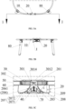
FIG. 4A is a schematic top view of a baby crib in an unfolded state according to an embodiment of the present application, with half of the structure of the baby crib omitted and a locking member being in a first locking position. -
FIG. 4B is a cross-sectional view taken along line A-A inFIG. 4A . -
FIG. 4C is a partially enlarged view of the portion H inFIG. 4B . -
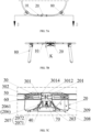
FIG. 5A is a schematic top view of a baby crib in an unfolded state according to an embodiment of the present application, with half of the structure of the baby crib omitted and a locking member being in a first locking position. -
FIG. 5B is a cross-sectional view taken along line B-B inFIG. 5A . -
FIG. 5C is a partially enlarged view of the portion I inFIG. 5B . -
FIG. 6A is a schematic top view of a baby crib in an unfolded state according to an embodiment of the present application, with half of the structure of the baby crib omitted, and a locking member in a first unlocking position. -
FIG. 6B is a cross-sectional view taken along line C-C inFIG. 6A . -
FIG. 6C is a partially enlarged view of the portion J inFIG. 6B . -
FIG. 7A is a schematic top view of a baby crib in an unfolded state according to an embodiment of the present application, with half of the structure of the baby crib omitted and a locking member in a first unlocking position. -
FIG. 7B is a cross-sectional view taken along line D-D inFIG. 7A . -
FIG. 7C is a partially enlarged view of the portion K inFIG. 7B . -
FIG. 8A is a schematic top view of a baby crib in a folded state according to an embodiment of the present application. -
FIG. 8B is a cross-sectional view taken along line E-E inFIG. 8A . -
FIG. 8C is a partially enlarged view of the portion L inFIG. 8B . -
FIG. 9 is a schematic structural view of a locking member according to an embodiment of the present application. -
FIG. 10 is a schematic structural view of a fixing base according to an embodiment of the present application. -
FIG. 11 is a schematic structural view of an operating member according to an embodiment of the present application. - Reference numeral list:
- 1-folding mechanism; 2-baby crib;
- 10-handrail tube; 101-pivoting end; 1011-first hole;
- 20-fixing base; 201-locking hole; 202-third hole; 203-accommodating cavity; 204-connecting groove; 205-through hole; 206-guiding rib; 2061-arched guiding face; 207-limiting portion; 2071-limiting step; 2072-limiting face;
- 30-locking member; 301-locking end; 3011-cooperating slope; 3012-end face; 3013-recess; 3014-anti-rotation portion; 302-second hole;
- 40-operating member; 401-driving portion; 4011-driving slope;
- 50-pivoting member;
- 60-first resilient member;
- 70-second resilient member;
- SO-support post.
- It should be noted that when an element is referred to as being "connected" to another element, it can be directly connected to or integrated with the other element or intervening elements may be present. The expressions such as "mounted", "an end", "the other end", and the like used herein are merely for illustrative purposes.
- Unless otherwise defined, all the technical and scientific terms used herein have the same meanings as the meanings commonly understood by a person skilled in the art. The term "and/or" used herein includes any and all combinations of one or more of the associated listed items.
- Referring to
FIG. 1A, FIG. 1B , andFIG. 2 , ababy crib 2 is provided in an embodiment of the present application. Thebaby crib 2 includes afolding mechanism 1 and support posts 80. The user can fold thebaby crib 2 from an unfolded state as shown inFIG. 1A and FIG. 1B to a folded state as shown inFIG. 2 by operating thefolding mechanism 1. In the present application, the term "vertical direction" is defined as a direction perpendicular to a horizontal surface on which thebaby crib 2 is placed, as shown with the direction D1 inFIG. 1 . Referring toFIG. 3 ,FIG. 4A, FIG. 4B, and FIG. 4C , in the present application, the term "lateral direction" is defined as a right-left direction ofFIG. 4B , as shown with the direction D2 inFIG. 4B , which is perpendicular to the direction D1. In an embodiment, thefolding mechanism 1 includes ahandrail tube 10, a fixingbase 20, a lockingmember 30, and an operatingmember 40. Thehandrail tube 10 includes a pivotingend 101 which is inserted into and pivotally connected to the fixingbase 20. Thehandrail tube 10 is pivotally connected to a lateral end of the fixingbase 20. Thehandrail tube 10 is pivotable between an unfolded position and a folded position relative to the fixingbase 20. The lockingmember 30 is at least partially movably sleeved into an inner hole in the pivotingend 101 of thehandrail tube 10. The lockingmember 30 is slidable between a first locking position and a first unlocking position. The operatingmember 40 is slidably connected to the fixingbase 20 and slidable between a second locking position and a second unlocking position. When the operatingmember 40 slides from the second locking position to the second unlocking position, the operatingmember 40 can drive the lockingmember 30 to slide from the first locking position to the first unlocking position. In the first locking position, the lockingmember 30 prohibits the pivoting of thehandrail tube 10 relative to the fixingbase 20. In the first unlocking position, the lockingmember 30 allows the pivoting of thehandrail tube 10 relative to the fixingbase 20. Specifically, the user operates the operatingmember 40 such that the operatingmember 40 slides from the second locking position to the second unlocking position and drives the lockingmember 30 to slide from the first locking position to the first unlocking position. In this way, the locking to the pivoting of thehandrail tube 10 by the lockingmember 30 is released, so that the user can pivot thehandrail tube 10 from the unfolded position to the folded position to fold thebaby crib 2. - Referring to
FIG. 4C in combination withFIG. 9 , in an embodiment, the lockingmember 30 has a lockingend 301 provided with a cooperatingslope 3011. The operatingmember 40 is provided with adriving slope 4011 in driving cooperation with the cooperatingslope 3011. When the operatingmember 40 slides from the second locking position to the second unlocking position, the drivingslope 4011 abuts against and presses the cooperatingslope 3011 to drive the lockingmember 30 to slide from the first locking position to the first unlocking position. The fixingbase 20 is provided with alocking hole 201 therein. When the lockingmember 30 is in the first locking position, the lockingend 301 is positioned inside the lockinghole 201 to prohibit the pivoting of thehandrail tube 10 relative to the fixingbase 20. When the lockingmember 30 is in the first unlocking position, the lockingend 301 is positioned outside the lockinghole 201 to allow the pivoting of thehandrail tube 10 relative to the fixingbase 20. - Referring to
FIG. 4C andFIG. 6C , inFIG. 4C , the lockingmember 30 is in the first locking position and the operatingmember 40 is in the second locking position, while inFIG. 6C , the lockingmember 30 is in the first unlocking position and the operatingmember 40 is in the second unlocking position. In the state shown inFIG. 4C , the lockingend 301 of the lockingmember 30 is inserted into thelocking hole 201, and thedriving slope 4011 of the operatingmember 40 applies no pressure or only slight pressure to the cooperatingslope 3011 of the lockingmember 30, such that the lockingend 301 of the lockingmember 30 is unable to exit from the lockinghole 201. At this time, as a portion of the lockingmember 30 other than the lockingend 301 is inserted into the inner hole of the pivotingend 101 of thehandrail tube 10, and the lockingend 301 of the lockingmember 30 is inserted into thelocking hole 201, thehandrail tube 10 is unable to pivot relative to the fixingbase 20. In the state shown inFIG. 4C , the user operates (e.g., presses) the operatingmember 40 such that the drivingslope 4011 of the operatingmember 40 applies a certain pressure to the cooperatingslope 3011 of the lockingmember 30. Through the driving cooperation of thedriving slope 4011 with the cooperatingslope 3011, the lockingmember 30 slides in a direction away from the lockinghole 201 until the lockingend 301 of the lockingmember 30 retreats out of thelocking hole 201. At this time, thehandrail tube 10 is able to pivot relative to the fixingbase 20. - Referring again to
FIG. 9 , in an embodiment, the lockingmember 301 is in a substantially cylindrical shape. Alternatively, the lockingmember 301 may be in any other suitable shape, such as a prismatic shape, as long as it meets the requirements for cooperating with the pivotingend 101 of thehandrail tube 10 and with thelocking hole 201. The lockingend 301 is formed with arecess 3013 on anend face 3012 thereof. A bottom face of therecess 3013 is inclined relative to theend face 3012 of the lockingend 301 to form the cooperatingslope 3011. - Referring to
FIG. 5C andFIG. 7C , inFIG. 5C , the lockingmember 30 is in the first locking position and the operatingmember 40 is in the second locking position; and inFIG. 7c , the lockingmember 30 is in the first unlocking position and the operatingmember 40 is in the second unlocking position. In an embodiment, a portion of the lockingend 301 of the lockingmember 30 other than therecess 3013 forms ananti-rotation portion 3014. In the state shown inFIG. 5C , the lockingend 301 of the lockingmember 30 is inserted into thelocking hole 201, and theanti-rotation portion 3014 engages with the inner wall of thelocking hole 201 to prevent the pivoting the locking member, thereby preventing the pivoting of thehandrail tube 10 relative to the fixingbase 20. In the state shown inFIG. 7C , the lockingend 301 of the lockingmember 30 is retreated out of thelocking hole 201, and thehandrail tube 10 is able to pivot relative to the fixingbase 20. - Referring to
FIG. 4C andFIG. 11 , in an embodiment, the operatingmember 40 includes a drivingportion 401 extending in the vertical direction. The drivingslope 4011 is formed on an end of the drivingportion 401. The drivingslope 4011 can establish the driving cooperation with the cooperatingslope 3011 within therecess 3013. - Referring to
FIG. 4C in combination withFIG. 9, and FIG. 10 , specifically, the end of the drivingportion 401 of the operatingmember 40 enters into therecess 3013 of the lockingend 301 of the lockingmember 30 to allow thedriving slope 4011 to come into contact with the cooperatingslope 3011 to achieve the driving cooperation therebetween. - Referring to
FIG. 2, FIG. 3 ,FIG. 4C , andFIG. 10 , in an embodiment, the pivotingend 101 of thehandrail tube 10 is provided with afirst hole 1011. The lockingmember 30 is provided with asecond hole 302. The fixingbase 20 is provided with athird hole 202. A pivotingmember 50 passes through thefirst hole 1011, thesecond hole 302, and thethird hole 202 to allow thehandrail tube 10 and the lockingmember 30 to pivot relative to the fixingbase 20 about the pivoting axis X (seeFigure 2 ). Optionally, thesecond hole 302 is an elongated hole which allows the lockingmember 30 to slide in the axial direction of thehandrail tube 10 between the first locking position and the first unlocking position. - Referring to
FIG. 4C , in an embodiment, thefolding mechanism 1 further includes a firstresilient member 60. One end of the firstresilient member 60 abuts against the pivotingmember 50, and the other end of the firstresilient member 60 abuts against the lockingmember 30. When thehandrail tube 10 is in the unfolded position, the firstresilient member 60 biases the lockingmember 30 toward the first locking position. In this embodiment, the firstresilient member 60 is a spring. Alternatively, the firstresilient member 60 may also be any other suitable resilient element, such as a leaf spring or a torsion spring, as long as it meets the requirements for biasing the lockingmember 30 toward the first locking position. As shown inFIG. 4C , as the firstelastic member 60 biases the lockingmember 30 toward the first locking position, the lockingend 301 of the lockingmember 30 constantly has a moving tendency of sliding toward thelocking hole 201. When there is no external force applied to the operatingmember 40, under the action of the firstelastic member 60, the lockingend 301 of the lockingmember 30 is kept in thelocking hole 201 i.e., the lockingmember 30 is kept in the first locking position. In this way, on the one hand, the baby crib can be kept in the unfolded state for convenient use, and on the other hand, the accidental folding of the baby crib can be avoided to ensure the safety of use. In this embodiment, one end of the firstelastic member 60 abuts against the pivotingmember 50, the other end of the firstelastic member 60 abuts against the lockingmember 30, and the pivotingmember 50 can slide in thesecond hole 302 in form of an elongated hole to enable the sliding of the lockingmember 30 in the axial direction of thehandrail tube 10 between the first locking position and the first unlocking position. In another embodiment not shown, the lockingmember 30 may include a fixing portion and a locking portion slidably connected to the fixing portion. For example, the locking portion is sleeved into the fixing portion and retractable relative to the fixing portion. The locking end is provided at an end of the locking portion away from the fixing portion. In such an embodiment, the lockingend 301 has the same structure as that of the lockingend 301 in the foregoing embodiment. Thesecond hole 302 is provided as a circular hole on the fixing portion. A diameter of the second hole is slightly larger than an outer diameter of the pivotingmember 50 to allow the pivotingmember 50 to pass through thesecond hole 302. When the pivotingmember 50 passes through thefirst hole 1011, thesecond hole 302, and thethird hole 202, the fixing portion is non-slidable in the axial direction of thehandrail tube 10. One end of the firstresilient member 60 abuts against the fixing portion, and the other end of the firstresilient member 60 abuts against the locking portion, so that the locking portion is slidably connected to the fixing portion through the firstresilient member 60, and the locking portion is able to slide between the first locking position and the first unlocking position in the axial direction of thehandrail tube 10. The firstresilient member 60 biases the locking portion towards the first locking position, and the lockingend 301 of the locking portion constantly has a moving tendency of sliding toward thelocking hole 201. When there is no external force applied to the operatingmember 40, the lockingend 301 of the lockingmember 30 is kept in thelocking hole 201 under the action of the firstresilient member 60 such that thehandrail tube 10 is unable to pivot relative to the fixingbase 20. When the operatingmember 40 is driven by an external force, the drivingslope 4011 of the operatingmember 40 applies a certain pressure to the cooperatingslope 3011 of the lockingend 301, and the lockingend 301 of the lockingmember 30 slides in a direction away from the lockinghole 201 until it is entirely retreated out of thelocking hole 201, allowing thehandrail tube 10 to pivot relative to the fixingbase 20. - Referring to
FIG. 4C in combination withFIG. 10 , in an embodiment, the fixingbase 20 is provided with anaccommodating cavity 203 therein, and the operatingmember 40 is at least partially accommodated in theaccommodating cavity 203. Thefolding mechanism 1 further includes a secondresilient member 70. One end of the secondresilient member 70 abuts against the operatingmember 40, and the other end of the secondresilient member 70 abuts against the fixingbase 20. The secondresilient member 70 biases the operatingmember 40 toward the second locking position. In this embodiment, the secondresilient member 70 is a spring. Alternatively, the secondresilient member 70 may be any other suitable resilient element, such as a leaf spring and a torsion spring, as long as it meets the requirements for biasing the operatingmember 40 toward the second locking position. As the secondresilient member 70 biases the operatingmember 40 toward the second locking position, the operatingmember 40 constantly has a tendency of moving downward in the vertical direction. When there is no external force applied to the operatingmember 40, the operatingmember 40 is kept in the second locking position. At this time, the drivingslope 4011 of the operatingmember 40 applies no or only slight pressure to the cooperatingslope 3011 of the lockingmember 30, and under the action of the firstresilient member 60, the lockingend 301 of the lockingmember 30 is kept in thelocking hole 201, i.e., the lockingmember 30 is kept in the first locking position, while the operatingmember 40 is kept in the second locking position. - Referring to
FIG. 4C ,FIG. 10, and FIG. 11 , in an embodiment, the operatingmember 40 is provided with a connectingprotrusion 402 thereon. A side wall in theaccommodating cavity 203 is provided with a connectinggroove 204 in cooperation with the connectingprotrusion 402. When the operatingmember 40 slides relative to the fixingbase 20, the connectingprotrusion 402 slides along the connectinggroove 204. The connectinggroove 204 is an elongated groove extending in the vertical direction. Specifically, a lower end of the connectinggroove 204 in the vertical direction is positioned such that when the operatingmember 40 slides to such an extent that the connectingprotrusion 402 abuts against the lower end of the connectinggroove 204 in the vertical direction, the operatingmember 40 is in the second locking position. An upper end of the connectinggroove 204 in the vertical direction is positioned such that when the operatingmember 40 slides to such an extent that the connectingprotrusion 402 abuts against the upper end of the connectinggroove 204 in the vertical direction, the operatingmember 40 is in the second unlocking position. - Referring to
FIG. 10 , a top wall of theaccommodating cavity 203 is provided with a throughhole 205 in communication with thelocking hole 201. The drivingportion 401 passes through the throughhole 205 to cooperate with the lockingend 301 of the lockingmember 30. Optionally, the lockinghole 201 is provided in the upper portion of the fixingbase 20 and extends in the lateral direction of the fixingbase 20. - Referring to
FIG. 6C in combination withFIG. 8C , the fixingbase 20 is provided with a guidingrib 206. The guidingrib 206 extends from the lower side of thelocking hole 201 to the lateral end of the fixingbase 20. The guidingrib 206 is provided with anarched guiding face 2061 at a side thereof facing thehandrail tube 10. When thehandrail tube 10 pivots relative to the fixingbase 20, the lockingend 301 of the lockingmember 30 slides on thearched guiding face 2061. Specifically, when the lockingmember 30 is in the first unlocking state shown inFIG. 6C , the user can pivot thehandrail tube 10 about the axis X (seeFIG. 2 ) from the unfolded position to the folded position shown inFIG. 8C . - Still referring to
FIG. 6C andFIG. 8C , in an embodiment, the fixingbase 20 further includes a limitingportion 207 disposed at a side of the guidingrib 206 proximate to the lateral end of the fixingbase 20. When thehandrail tube 10 is in the folded position, the limitingportion 207 prohibits the pivoting of thehandrail tube 10 toward the unfolded position. The limitingportion 207 includes a limitingstep 2071 and a limitingface 2072. The limitingstep 2071 is disposed between the limitingface 2072 and thearched guiding face 2061. The fixingbase 20 further includes abottom wall 208 and aside wall 209. The limitingface 2072 is provided at a side of thebottom wall 208 facing the interior space of the fixingbase 20. Thebottom wall 208 at least partially covers the interior space of the fixingbase 20. - In this embodiment, the
arched guiding face 2061, the limitingstep 2071, the limitingface 2072, and theside wall 209 collectively define a pivoting space. When thehandrail tube 10 pivots, the pivotingend 101 of thehandrail tube 10 pivots in this pivoting space, and the lockingend 301 of the lockingmember 30 slides on thearched guiding face 2061, the limitingstep 2071, and the limitingface 2072. Specifically, when thehandrail tube 10 pivots from the unfolded position shown inFIG. 6C to the folded position shown inFIG. 8C , the pivotingend 101 of thehandrail tube 10 pivots from a substantially horizontal orientation to a substantially vertical orientation. Under the action of the secondresilient member 60, the lockingend 301 of the lockingmember 30 presses against and slides sequentially on thearched guiding face 2061, the limitingstep 2071, and the limitingface 2072. When the lockingend 301 slides over the limitingstep 2071 to the limitingface 2072, under the action of the secondelastic member 60, the lockingmember 30 protrudes only a short distance in a direction away from the pivoting center to press against the limitingface 2072, because the distance W between the limitingface 2072 and the pivoting center of thehandrail tube 10 is greater than the distance R between thearched guiding face 2061 and the pivoting center of thehandrail tube 10. At this time, theanti-rotation portion 3014 of the lockingmember 30 abuts against the limitingface 2072 to prevent thehandrail tube 10 from pivoting toward the unfolded position, thereby preventing the accidental unfolding of thehandrail tube 10 in the folded position and improving the safety of use. - In this embodiment, the limiting
step 2071 has a curved face. When thehandrail tube 10 has the moving tendency of pivoting toward the unfolded position, the curved face in engagement with theanti-rotation portion 3014 applies a pressure toward the pivoting center to theanti-rotation portion 3014. As the moving tendency of thehandrail tube 10 pivoting toward the unfolded position increases (for example, as the force driving thehandrail tube 10 to pivot toward the unfolded position increases), the pressure toward the pivoting center that is applied to theanti-rotation portion 3014 by the curved face increases. When the pressure toward the pivoting center that is applied to theanti-rotation portion 3014 by the curved face is greater than the resilient force provided by the secondresilient member 60, theanti-rotation portion 3014 of the lockingmember 30 retracts toward the pivoting center, so that theanti-rotation portion 3014 is able to slide over the limitingstep 2071 to thearched guiding face 2061. At this time, the limitingstep 2071 no longer prevents the pivoting of thehandrail tube 10 toward the unfolded position. Specifically, when in use, the user only needs to apply a certain external force to thehandrail tube 10 to overcome the obstruction of the limitingstep 2071 so that thehandrail tube 10 pivots towards the unfolded position to unfold thebaby crib 2. - Referring again to
FIG. 10 , thebottom wall 208 at least partially covers the interior space of the fixingbase 20. When the user presses the operatingmember 40, the user's fingers will be blocked by thebottom wall 208 from entering the interior space of the fixingbase 20. This avoids the risk of the user's finger being pinched by a component in the interior space of the fixing base 20 (e.g., the operatingmember 40, the lockingmember 30, or the pivotingend 101 of thehandrail tube 10, etc.). Optionally, the fixingbase 20 further includes a side wall which at least partially covers the interior space of the fixingbase 20 to avoid the risk of the user's fingers entering the fixing base from a side of the fixing base and getting pinched.
Claims (15)
- A folding mechanism (1) for a baby crib (2), comprising:a handrail tube (10) pivotable between an unfolded position and a folded position;a fixing base (20) having a lateral end pivotably connected to the handrail tube (10);a locking member (30) movably sleeved into a pivoting end (101) of the handrail tube (10) and slidable between a first locking position and a first unlocking position; andan operating member (40) slidably connected to the fixing base (20) and slidable between a second locking position and a second unlocking position;wherein, when the operating member (40) slides from the second locking position to the second unlocking position, the operating member (40) drives the locking member (30) to slide from the first locking position to the first unlocking position;wherein in the first locking position, the locking member (30) prohibits the handrail tube (10) from pivoting, and in the first unlocking position, the locking member (30) allows the handrail tube (10) to pivot.
- The folding mechanism (10) of claim 1, wherein the locking member (30) has a locking end (301) provided with a cooperating slope (3011), the operating member (40) is provided with a driving slope (4011) in driving cooperation with the cooperating slope (3011), and when the operating member (40) slides from the second locking position to the second unlocking position, the driving slope (4011) abuts against and presses the cooperating slope (3011) to drive the locking member (30) to slide from the first locking position to the first unlocking position.
- The folding mechanism (10) of claim 2, wherein the locking end (301) is provided with a recess (3013) on an end face (3012) thereof, and a bottom face of the recess (3013) is inclined relative to the end face (3012) of the locking end (301) to form the cooperating slope (3011).
- The folding mechanism (10) of claim 2 or 3, wherein the operating member (40) comprises a driving portion (401) extending in a sliding direction thereof, the driving slope (4011) is formed on an end of the driving portion (401), and the driving slope (4011) drivingly cooperates with the cooperating slope (3011) within the recess (3013).
- The folding mechanism (10) of any one of the preceding claims, wherein the pivoting end (101) of the handrail tube (10) is provided with a first hole (1011), the locking member (30) is provided with a second hole (302), the fixing base (20) is provided with a third hole (202), and a pivoting member (50) passes through the first hole (1011), the second hole (302), and the third hole (202) to allow the handrail tube (10) and the locking member (30) to pivot relative to the fixing base (20).
- The folding mechanism (10) of claim 5, wherein the second hole (302) is an elongated hole allowing the locking member (30) to slide in the axial direction of the handrail tube (10) between the first locking position and the first unlocking position.
- The folding mechanism (10) of claim 5 or 6, further comprising a first resilient member (60), wherein one end of the first resilient member (60) abuts against the pivoting member (50), the other end of the first resilient member (60) abuts against the locking member (30), and when the handrail tube (10) is in the unfolded position, the first resilient member (60) biases the locking member (30) toward the first locking position.
- The folding mechanism (10) of any one of the preceding claims, wherein the fixing base (20) is provided with a locking hole (201) therein, wherein preferably, the locking hole (201) is provided in an upper portion of the fixing base (20) and extends in a lateral direction of the fixing base (20); wherein, when the locking member (30) is in the first locking position, a locking end (301) of the locking member (30) is positioned inside the locking hole (201) to prohibit the handrail tube (10) from pivoting relative to the fixing base (20); and when the locking member (30) is in the first unlocking position, the locking end (301) of the locking member (30) is positioned outside the locking hole (201) to allow the handrail tube (10) to pivot relative to the fixing base (20).
- The folding mechanism (10) of claim 8, wherein the fixing base (20) is provided with a guiding rib (206) extending from a lower side of the locking hole (201) to the lateral end of the fixing base (20), the guiding rib (206) is provided with an arched guiding face (2061) on a side thereof facing the handrail tube (10), and when the handrail tube (10) pivots relative to the fixing base (20), the locking end (301) of the locking member (30) slides on the arched guiding face (2061).
- The folding mechanism (10) of claim 9, wherein the fixing base (20) further comprises a limiting portion (207) disposed at a side of the guiding rib (206) proximate to the lateral end of the fixing base (20), and when the handrail tube (10) is in the folded position, the limiting portion (207) prohibits the handrail tube (10) from pivoting toward the unfolded position.
- The folding mechanism (10) of claim 10, wherein the limiting portion (207) comprises a limiting step (2071) and a limiting face (2072), the limiting step (2071) is disposed between the limiting face (2072) and the arched guiding face (2061), and a distance between the limiting face (2072) and a pivoting center of the handrail tube (10) is greater than a distance between the arched guiding face (2061) and the pivoting center of the handrail tube (10).
- The folding mechanism (10) of any one of the preceding claims, wherein the fixing base (20) is provided with an accommodating cavity (203) therein, and the operating member (40) is at least partially accommodated in the accommodating cavity (203).
- The folding mechanism (10) of claim 12, wherein the operating member (40) is provided with a connecting protrusion (402) thereon, a side wall in the accommodating cavity (203) is provided with a connecting groove (204) in cooperation with the connecting protrusion (402), and when the operating member (40) slides relative to the fixing base (20), the connecting protrusion (402) slides along the connecting groove (204).
- The folding mechanism (10) of claim 12 or 13 in combination with any one of claims 8 to 11, wherein a top wall of the accommodating cavity (203) is provided with a through hole (205) in communication with the locking hole (201), the operating member (40) includes a driving portion (401) extending in a sliding direction thereof, and the driving portion (401) passes through the through hole (205) to cooperate with the locking end (301) of the locking member (30).
- The folding mechanism (10) of any one of the preceding claims, further comprising a second resilient member (70), wherein one end of the second resilient member (70) abuts against the operating member (40), the other end of the second resilient member (70) abuts against the fixing base (20), and the second resilient member (70) biases the operating member (40) toward the second locking position.
Applications Claiming Priority (1)
| Application Number | Priority Date | Filing Date | Title |
|---|---|---|---|
| CN202310710138.XA CN119138733A (en) | 2023-06-14 | 2023-06-14 | Folding mechanism |
Publications (1)
| Publication Number | Publication Date |
|---|---|
| EP4477114A1 true EP4477114A1 (en) | 2024-12-18 |
Family
ID=91580725
Family Applications (1)
| Application Number | Title | Priority Date | Filing Date |
|---|---|---|---|
| EP24182177.6A Pending EP4477114A1 (en) | 2023-06-14 | 2024-06-14 | Folding mechanism |
Country Status (4)
| Country | Link |
|---|---|
| US (1) | US20240415293A1 (en) |
| EP (1) | EP4477114A1 (en) |
| CN (1) | CN119138733A (en) |
| TW (1) | TW202537552A (en) |
Families Citing this family (2)
| Publication number | Priority date | Publication date | Assignee | Title |
|---|---|---|---|---|
| USD1120685S1 (en) * | 2023-09-04 | 2026-03-31 | Wonderland Switzerland Ag | Crib |
| CA233149S (en) * | 2024-01-16 | 2026-03-30 | China Wonderland Nurserygoods | Frame for crib |
Citations (5)
| Publication number | Priority date | Publication date | Assignee | Title |
|---|---|---|---|---|
| US20040071499A1 (en) * | 2002-09-26 | 2004-04-15 | Kenny Cheng | Foldable mechanism for playyard |
| CN2757686Y (en) * | 2004-12-10 | 2006-02-15 | 中山市隆成日用制品有限公司 | A foldable baby sleeping basket skeleton structure |
| CN208625065U (en) * | 2018-03-23 | 2019-03-22 | 厦门安宝贝妇幼用品有限公司 | Crib armrest joint folding device |
| CN217695832U (en) * | 2022-05-17 | 2022-11-01 | 厦门梦贝比儿童用品有限公司 | Folding recreation bed rod structure |
| WO2024040094A2 (en) * | 2022-08-17 | 2024-02-22 | Wonderland Switzerland Ag | Height adjustable playard including a collapsible child support assembly |
-
2023
- 2023-06-14 CN CN202310710138.XA patent/CN119138733A/en active Pending
-
2024
- 2024-06-12 US US18/741,378 patent/US20240415293A1/en active Pending
- 2024-06-14 EP EP24182177.6A patent/EP4477114A1/en active Pending
- 2024-06-14 TW TW114122435A patent/TW202537552A/en unknown
Patent Citations (5)
| Publication number | Priority date | Publication date | Assignee | Title |
|---|---|---|---|---|
| US20040071499A1 (en) * | 2002-09-26 | 2004-04-15 | Kenny Cheng | Foldable mechanism for playyard |
| CN2757686Y (en) * | 2004-12-10 | 2006-02-15 | 中山市隆成日用制品有限公司 | A foldable baby sleeping basket skeleton structure |
| CN208625065U (en) * | 2018-03-23 | 2019-03-22 | 厦门安宝贝妇幼用品有限公司 | Crib armrest joint folding device |
| CN217695832U (en) * | 2022-05-17 | 2022-11-01 | 厦门梦贝比儿童用品有限公司 | Folding recreation bed rod structure |
| WO2024040094A2 (en) * | 2022-08-17 | 2024-02-22 | Wonderland Switzerland Ag | Height adjustable playard including a collapsible child support assembly |
Also Published As
| Publication number | Publication date |
|---|---|
| TW202500061A (en) | 2025-01-01 |
| US20240415293A1 (en) | 2024-12-19 |
| CN119138733A (en) | 2024-12-17 |
| TW202537552A (en) | 2025-10-01 |
Similar Documents
| Publication | Publication Date | Title |
|---|---|---|
| US20240415293A1 (en) | Folding mechanism | |
| EP3782708B1 (en) | Automatic telescopic pole | |
| AU2021287862B2 (en) | Foldable tent | |
| AU2024204953A1 (en) | Foldable locking mechanism | |
| US20080034506A1 (en) | Changing table for playard | |
| EP2036825A1 (en) | A collapsible container | |
| US11375788B2 (en) | Luggage with support | |
| KR102899043B1 (en) | Folding height adjustable table | |
| EP0897848A1 (en) | Stroller | |
| US12311815B2 (en) | Child safety seat and side collision protection mechanism thereof | |
| US20030229968A1 (en) | Playyard latch mechanism | |
| US20260035028A1 (en) | Stroller frame and stroller | |
| US7823995B2 (en) | Slide assembly with transmitting mechanism | |
| US20250009120A1 (en) | Sliding positioning mechanism | |
| JP3136116U (en) | Umbrella handle that can increase length | |
| US20250283378A1 (en) | Ladder with lifting and lowering handrail | |
| TW202128477A (en) | Foldable backrest structure adapted for a frame of a child carrier and child carrier therewith | |
| CN114396207B (en) | Pressing rebound device convenient to buckle away | |
| CN113246828B (en) | Table component for vehicle and vehicle | |
| KR200223468Y1 (en) | Collapsible table | |
| CN223949023U (en) | Automatic falling lock locking mechanism and safety seat | |
| CN221265431U (en) | A parasol | |
| US6131590A (en) | Collapsible umbrella structure with hand protection | |
| CN221023367U (en) | Child safety seat support assembly | |
| JP2511622Y2 (en) | Automatic opening and closing mechanism of the umbrella |
Legal Events
| Date | Code | Title | Description |
|---|---|---|---|
| PUAI | Public reference made under article 153(3) epc to a published international application that has entered the european phase |
Free format text: ORIGINAL CODE: 0009012 |
|
| STAA | Information on the status of an ep patent application or granted ep patent |
Free format text: STATUS: REQUEST FOR EXAMINATION WAS MADE |
|
| 17P | Request for examination filed |
Effective date: 20240614 |
|
| AK | Designated contracting states |
Kind code of ref document: A1 Designated state(s): AL AT BE BG CH CY CZ DE DK EE ES FI FR GB GR HR HU IE IS IT LI LT LU LV MC ME MK MT NL NO PL PT RO RS SE SI SK SM TR |
|
| STAA | Information on the status of an ep patent application or granted ep patent |
Free format text: STATUS: EXAMINATION IS IN PROGRESS |
|
| 17Q | First examination report despatched |
Effective date: 20250926 |