EP4477098A1 - Electronic atomization device - Google Patents
Electronic atomization device Download PDFInfo
- Publication number
- EP4477098A1 EP4477098A1 EP24181191.8A EP24181191A EP4477098A1 EP 4477098 A1 EP4477098 A1 EP 4477098A1 EP 24181191 A EP24181191 A EP 24181191A EP 4477098 A1 EP4477098 A1 EP 4477098A1
- Authority
- EP
- European Patent Office
- Prior art keywords
- atomization
- cartridge chamber
- cartridge
- body portion
- electronic
- Prior art date
- Legal status (The legal status is an assumption and is not a legal conclusion. Google has not performed a legal analysis and makes no representation as to the accuracy of the status listed.)
- Pending
Links
Images




Classifications
-
- A—HUMAN NECESSITIES
- A24—TOBACCO; CIGARS; CIGARETTES; SIMULATED SMOKING DEVICES; SMOKERS' REQUISITES
- A24F—SMOKERS' REQUISITES; MATCH BOXES; SIMULATED SMOKING DEVICES
- A24F40/00—Electrically operated smoking devices; Component parts thereof; Manufacture thereof; Maintenance or testing thereof; Charging means specially adapted therefor
- A24F40/40—Constructional details, e.g. connection of cartridges and battery parts
-
- A—HUMAN NECESSITIES
- A24—TOBACCO; CIGARS; CIGARETTES; SIMULATED SMOKING DEVICES; SMOKERS' REQUISITES
- A24F—SMOKERS' REQUISITES; MATCH BOXES; SIMULATED SMOKING DEVICES
- A24F40/00—Electrically operated smoking devices; Component parts thereof; Manufacture thereof; Maintenance or testing thereof; Charging means specially adapted therefor
- A24F40/10—Devices using liquid inhalable precursors
-
- A—HUMAN NECESSITIES
- A24—TOBACCO; CIGARS; CIGARETTES; SIMULATED SMOKING DEVICES; SMOKERS' REQUISITES
- A24F—SMOKERS' REQUISITES; MATCH BOXES; SIMULATED SMOKING DEVICES
- A24F40/00—Electrically operated smoking devices; Component parts thereof; Manufacture thereof; Maintenance or testing thereof; Charging means specially adapted therefor
- A24F40/40—Constructional details, e.g. connection of cartridges and battery parts
- A24F40/42—Cartridges or containers for inhalable precursors
Definitions
- This application relates to the field of electronic atomization technologies, and in particular, to an electronic atomization device.
- An electronic atomization device is an atomization product that heats and atomizes a liquid substrate into an aerosol for a user to inhale.
- an electronic atomization device with a standby atomization cartridge is designed.
- an atomization cartridge chamber is generally arranged in a shell of an electronic atomization device, so that the standby atomization cartridge is placed into the atomization cartridge chamber.
- the atomization cartridge is placed into the shell of the electronic atomization device, and the atomization cartridge chamber is designed integrally with the shell.
- the atomization cartridge chamber occupies large space of the shell even when no standby atomization cartridge is loaded. Therefore, existing electronic atomization devices are not compact and portable enough as a result of a large shell volume.
- an embodiment of this application provides an electronic atomization device.
- An electronic atomization device includes:
- the atomization cartridge chamber is engaged with, inserted into, or magnetically connected to the body portion.
- the atomization cartridge chamber is connected to an end of the body portion along a longitudinal direction, or connected to a side of the body portion along a transverse direction.
- the shell has a first end and a second end that are opposite along a longitudinal direction, the first end is provided with a suction nozzle, and the atomization cartridge chamber is detachably connected to the second end.
- an end of the atomization cartridge chamber connected to the shell is provided with an opening, the opening is configured for the atomization cartridge to be taken out from and placed into the atomization cartridge chamber, and the opening is engaged with the second end, so that the atomization cartridge chamber is engaged with the second end.
- the second end of the shell is provided with a limiting step surface, and an end of the atomization cartridge chamber provided with the opening abuts against the limiting step surface to limit the atomization cartridge chamber.
- a bottom wall or a side wall of the atomization cartridge chamber is provided with a first air inlet hole, and the second end is provided with a second air inlet hole. In this way, an airflow channel extending through the second air inlet hole from the first air inlet hole to the suction nozzle is formed in the electronic atomization device.
- the atomization core is arranged in the body portion or in the atomization cartridge.
- the atomization core is arranged in the body portion, and the atomization core includes:
- the atomization cartridge includes:
- a housing of the atomization cartridge chamber is constructed to be at least partially transparent or semitransparent, so as to display the atomization cartridge inside the atomization cartridge chamber.
- the atomization cartridge chamber is detachably connected to the body portion.
- the atomization cartridge chamber of the electronic atomization device does not occupy space inside the shell, so that a volume of the body portion is relatively small.
- the body portion becomes an independent electronic atomization device with a small volume for users to use, and the electronic atomization device is compact and portable.
- the atomization cartridge chamber may be directly connected to the body portion, to facilitate carrying.
- the atomization cartridge chamber is connected to outside of the body portion, so that the overall shape is novel and unique.
- the atomization cartridge chamber may also be arranged as a transparent structure, so that the appearance is more novel and more beautiful.
- an electronic atomization device 100 includes a body portion 110 and an atomization cartridge chamber 120.
- the atomization cartridge chamber 120 is detachably connected to the body portion 110, which is specifically detachably connected to outside of the body portion 110, and the atomization cartridge chamber 120 is configured to store a standby atomization cartridge 121.
- the body portion 110 includes a shell 111 and a battery 101 arranged in the shell 111.
- a first accommodating space A is arranged in the shell 111, and the first accommodating space A is configured for the atomization cartridge 121 to be mounted.
- the atomization cartridge 121 may be mounted in the shell 111 before use, or may be taken out of the atomization cartridge chamber 120 and mounted in the shell 111 when in use, which is not limited herein.
- the body portion 110 of this embodiment of this application may include the atomization cartridge 121, or may not include the atomization cartridge 121.
- a second accommodating space B for storing at least one atomization cartridge 121 is arranged in the atomization cartridge chamber 120.
- the first accommodating space A is configured to removably receive the atomization cartridge from the second accommodating space B.
- the electronic atomization device 100 further includes an atomization core 112.
- a liquid substrate is stored in the atomization cartridge 121.
- the atomization core 112 is configured to heat the liquid substrate to generate an aerosol, and the battery 101 supplies power to the atomization core 112, so that the atomization core 112 heats the liquid substrate in the atomization cartridge 121 to form an aerosol.
- the atomization core 112 may be arranged in the body portion 100 or in the atomization cartridge 121. In an embodiment, as shown in FIG. 4 , the atomization core 112 is arranged in the body portion 110. Specifically, the atomization core 112 is arranged in the shell 111 of the body portion 110, and the atomization core 112 can receive an electric power of the battery 101 to heat the liquid substrate in the atomization cartridge 121 to form an aerosol. In another optional embodiment, the atomization core 112 may also be integrated in the atomization cartridge 121. One atomization core 112 is arranged in each atomization cartridge 121.
- the atomization core 112 When the atomization cartridge 121 is mounted to the shell 111, the atomization core 112 may be electrically connected to the battery 101, so that the battery 101 supplies power to the atomization core 112.
- the liquid substrate may include mainly one or more of components such as glycerol, propylene glycol, a nicotine preparation, flavors and fragrances, and flavor additives.
- the atomization cartridge chamber 120 is detachably connected to the body portion 110.
- the atomization cartridge chamber 120 is detachably connected to the outside of the body portion 110.
- the atomization cartridge chamber 120 in this embodiment of this application does not occupy the space in the shell 111, so that the volume of the body portion 110 is relatively small. As shown in FIG.
- the atomization cartridge chamber 120 may be removed from the body portion 110, and in this case, the body portion 110 becomes an independent electronic atomization device with a small volume, and the electronic atomization device is compact, portable, and convenient to use.
- the atomization cartridge chamber 120 may be directly connected to the body portion 110, so as to facilitate carrying and avoid causing scattered parts and inconvenience of carrying due to separation of the atomization cartridge chamber 120 from the body portion 110.
- the atomization cartridge chamber 120 is connected to outside of the body portion 110, so that the overall shape is novel and unique.
- a housing of the atomization cartridge chamber 120 may also be constructed to be at least partially transparent or semitransparent, so as to display the atomization cartridge 121 inside the atomization cartridge chamber 120.
- the atomization cartridge 121 in the atomization cartridge chamber 120 may be seen from the outside of the atomization cartridge chamber 120, so that the appearance of the entire electronic atomization device 100 is more novel and more beautiful. It is preferable to arrange the entire atomization cartridge chamber 120 as a transparent structure, so that the atomization cartridge 121 in the atomization cartridge chamber 120 can be completely seen from the outside.
- the atomization cartridge 121 may be set in various colors, and a plurality of atomization cartridges 121 may be set in the same color or in different colors.
- the colorful atomization cartridges 121 in the atomization cartridge chamber 120 are seen from the outside of the atomization cartridge chamber 120, so as to greatly improve a visual effect.
- one or more atomization cartridges 121 are stored in the atomization cartridge chamber 120.
- one atomization cartridge 121 is mounted in the body portion 110.
- Three atomization cartridges 121 are stored in the atomization cartridge chamber 120.
- Each of the atomization cartridges 121 may be placed vertically in the atomization cartridge chamber 120, or may be placed horizontally in the atomization cartridge chamber 120.
- the atomization cartridges 121 may be successively stacked along a vertical direction.
- the atomization cartridge chamber 120 is detachably connected to the body portion 110 in a number of manners.
- the atomization cartridge chamber 120 can be removably connected to the body portion 110 through engagement, insertion, or magnetic attraction.
- the atomization cartridge chamber 120 is engaged onto the body portion 110.
- an insertion structure such as a slot may also be arranged between the atomization cartridge chamber 120 and the body portion 110, to insert the atomization cartridge chamber 120 into the body portion 110.
- the atomization cartridge chamber 120 is connected to an end of the body portion 110 along a longitudinal direction.
- the atomization cartridge chamber 120 may also be connected to a side of the body portion 110 along a transverse direction.
- the atomization cartridge chamber 120 is engaged with the end of the body portion 110 along the longitudinal direction.
- the atomization cartridge chamber 120 may also be engaged with a side of the body portion 110 along a transverse direction.
- the shell 111 has a first end a and a second end b that are opposite along the longitudinal direction.
- the first end a is provided with a suction nozzle 113
- the atomization cartridge chamber 120 is detachably connected to the second end b.
- the atomization cartridge chamber 120 is arranged at an opposite end of the suction nozzle 113, so as to prevent the atomization cartridge chamber 120 from interfering with the suction nozzle 113, and ensure that a user can normally inhale the aerosol from the suction nozzle 113.
- the detachable connection between the atomization cartridge chamber 120 and the second end b is preferably engagement.
- an end of the atomization cartridge chamber 120 connected to the shell 111 is provided with an opening 122, and the opening 122 is configured for the atomization cartridge 121 to be taken out from and placed into the atomization cartridge chamber 120.
- the opening 122 is engaged with the second end b, so that the atomization cartridge chamber 120 is engaged with the second end b.
- the above structural design is not only convenient to take out and place the atomization cartridge 121 by using the opening 122, but also can be engaged with the shell 111 by using the opening 122, so that an engagement structure does not need to be separately designed, and the overall structure is simplified.
- the second end b of the shell 111 is provided with a limiting step surface 1111, and an end of the atomization cartridge chamber 120 provided with the opening 122 abuts against the limiting step surface 1111, to limit the atomization cartridge chamber 120.
- the shell 111 includes two parts with different sizes which are adjacent to each other along the longitudinal direction. The part with a smaller size is close to the atomization cartridge chamber 120, and the limiting step surface 1111 is formed between the two parts with different sizes.
- the limiting step surface 1111 is an end surface of the larger part.
- the atomization cartridge chamber 120 is engaged with the part with a smaller size and abuts against the end surface of the part with a larger size.
- an inner wall of the opening 122 of the atomization cartridge chamber 120 is provided with a vertical convex rib 123.
- the convex rib 123 facilitates the engagement between the atomization cartridge chamber 120 and the shell 111, so that the atomization cartridge chamber 120 can be engaged with the shell 111 more tightly.
- the first end a of the shell 111 is provided with the suction nozzle 113, and the atomization cartridge chamber 120 is engaged with the second end b of the shell 111.
- a bottom wall or a side wall of the atomization cartridge chamber 120 is provided with a first air inlet hole 124, and the second end b of the shell 111 is provided with a second air inlet hole 1112.
- the first air inlet hole 124 is preferably arranged on the bottom wall of the atomization cartridge chamber 120.
- the atomization core 112 is arranged in the body portion 110.
- the atomization core 112 includes an air tube 1121, a porous body 1122, and a heating net 1123.
- the air tube 1121 is fixedly mounted in the shell 111, and the air tube 1121 is arranged along the longitudinal direction, so as to facilitate subsequent insertion of the atomization cartridge 121 into outside of the air tube 1121 along the longitudinal direction.
- FIG. 5 the air tube 1121 is fixedly mounted in the shell 111, and the air tube 1121 is arranged along the longitudinal direction, so as to facilitate subsequent insertion of the atomization cartridge 121 into outside of the air tube 1121 along the longitudinal direction.
- a center of the atomization cartridge 121 is provided with a through hole 1211 for the air tube 1121 to pass, and the air tube 1121 extends through the through hole 1211 to assemble the atomization cartridge 121 with the atomization core 112.
- a side wall of the air tube 1121 is provided with a liquid inlet hole 1121a, and the liquid substrate in the atomization cartridge 121 enters the air tube 1121 through the liquid inlet hole 1121a.
- the porous body 1122 is arranged in the air tube 1121, and an outer surface of the porous body 1122 covers the liquid inlet hole 1121a, thereby receiving the liquid substrate entering the air tube 1121 through the liquid inlet hole 1121a.
- the heating net 1123 is arranged in the porous body 1122, and the heating net 1123 is electrically connected to the battery 101, so that the battery 101 supplies power to the heating net 1123.
- the heating net 1123 can heat the liquid substrate to form an aerosol after being electrified.
- the aerosol is outputted along the air tube 1121.
- the porous body 1122 may be, for example, a porous ceramic or a porous member made of another material.
- the structural design of the atomization core 112 enables the atomization cartridge 121 to be directly inserted into the air tube 1121 of the atomization core 112, so as to facilitate installation and disassembly and replacement of the atomization cartridge 121.
- the atomization cartridge 121 includes a housing 1212, a top cover 1213, a bottom cover 1214, and a liquid storage cotton 1215.
- the housing 1212 is cylindrical.
- the liquid storage cotton 1215 is arranged in the housing 1212, and the liquid storage cotton 1215 holds the liquid substrate.
- the top cover 1213 and the bottom cover 1214 respectively cover two ends of the housing 1212 along the longitudinal direction, thereby fixing the liquid storage cotton 1215 in the housing 1212.
- the top cover 1213, the bottom cover 1214, and the liquid storage cotton 1215 are all correspondingly provided with holes, thereby forming the through hole 1211 in the center of the atomization cartridge 121.
- the atomization cartridge 121 is inserted into the air tube 1121, so that the liquid substrate in the liquid storage cotton 1215 can enter the air tube 1121 through the liquid inlet hole 1121a on the air tube 1121 and be heated and atomized by the heating net 1123.
- the above structural design of the atomization cartridge 121 is convenient to mate with the atomization core 112, thereby realizing convenient and quick assembly and disassembly.
Landscapes
- Catching Or Destruction (AREA)
- Disinfection, Sterilisation Or Deodorisation Of Air (AREA)
Abstract
This application discloses an electronic atomization device. The electronic atomization device includes: a body portion, including a shell and a battery arranged in the shell, where a first accommodating space is arranged in the shell; an atomization cartridge chamber, detachably connected to the body portion, where a second accommodating space for storing at least one atomization cartridge is arranged in the atomization cartridge chamber, and a liquid substrate is stored in the atomization cartridge; and an atomization core. The first accommodating space is configured to removably receive the atomization cartridge from the second accommodating space, and the battery supplies power to the atomization core, so that the atomization core heats the liquid substrate in the atomization cartridge. The atomization cartridge chamber of the electronic atomization device is detachably connected to the body portion.
Description
- This application relates to the field of electronic atomization technologies, and in particular, to an electronic atomization device.
- An electronic atomization device is an atomization product that heats and atomizes a liquid substrate into an aerosol for a user to inhale. To facilitate replacement of an atomization cartridge after the user uses up an atomization cartridge, an electronic atomization device with a standby atomization cartridge is designed. In the known related art, an atomization cartridge chamber is generally arranged in a shell of an electronic atomization device, so that the standby atomization cartridge is placed into the atomization cartridge chamber. In other words, the atomization cartridge is placed into the shell of the electronic atomization device, and the atomization cartridge chamber is designed integrally with the shell. The atomization cartridge chamber occupies large space of the shell even when no standby atomization cartridge is loaded. Therefore, existing electronic atomization devices are not compact and portable enough as a result of a large shell volume.
- To resolve the above technical problem, an embodiment of this application provides an electronic atomization device.
- An electronic atomization device includes:
- a body portion, including a shell and a battery arranged in the shell, where a first accommodating space is arranged in the shell;
- an atomization cartridge chamber, detachably connected to the body portion, where a second accommodating space for storing at least one atomization cartridge is arranged in the atomization cartridge chamber, and a liquid substrate is stored in the atomization cartridge; and
- an atomization core, configured to heat the liquid substrate to generate an aerosol, where
- the first accommodating space is configured to removably receive the atomization cartridge from the second accommodating space, and the battery supplies power to the atomization core, so that the atomization core heats the liquid substrate in the atomization cartridge.
- As an optional solution of the above electronic atomization device, the atomization cartridge chamber is engaged with, inserted into, or magnetically connected to the body portion.
- As an optional solution of the above electronic atomization device, the atomization cartridge chamber is connected to an end of the body portion along a longitudinal direction, or connected to a side of the body portion along a transverse direction.
- As an optional solution of the above electronic atomization device, the shell has a first end and a second end that are opposite along a longitudinal direction, the first end is provided with a suction nozzle, and the atomization cartridge chamber is detachably connected to the second end.
- As an optional solution of the above electronic atomization device, an end of the atomization cartridge chamber connected to the shell is provided with an opening, the opening is configured for the atomization cartridge to be taken out from and placed into the atomization cartridge chamber, and the opening is engaged with the second end, so that the atomization cartridge chamber is engaged with the second end.
- As an optional solution of the above electronic atomization device, the second end of the shell is provided with a limiting step surface, and an end of the atomization cartridge chamber provided with the opening abuts against the limiting step surface to limit the atomization cartridge chamber.
- As an optional solution of the above electronic atomization device, a bottom wall or a side wall of the atomization cartridge chamber is provided with a first air inlet hole, and the second end is provided with a second air inlet hole. In this way, an airflow channel extending through the second air inlet hole from the first air inlet hole to the suction nozzle is formed in the electronic atomization device.
- As an optional solution of the above electronic atomization device, the atomization core is arranged in the body portion or in the atomization cartridge.
- As an optional solution of the above electronic atomization device, the atomization core is arranged in the body portion, and the atomization core includes:
- an air tube, arranged in the shell along a longitudinal direction, where a liquid inlet hole is provided on a side wall of the air tube, a through hole is provided at a center of the atomization cartridge for the air tube to pass, and the air tube extends through the through hole to fit the atomization cartridge with the atomization core;
- a porous body, arranged in the air tube, where an outer surface of the porous body covers the liquid inlet hole; and
- a heating net, arranged in the porous body, where the heating net is electrically connected to the battery, so that the battery supplies power to the heating net.
- As an optional solution of the above electronic atomization device, the atomization cartridge includes:
- a cylindrical housing; and
- a liquid storage cotton, arranged in the cylindrical housing, where the liquid storage cotton holds the liquid substrate.
- As an optional solution of the above electronic atomization device, a housing of the atomization cartridge chamber is constructed to be at least partially transparent or semitransparent, so as to display the atomization cartridge inside the atomization cartridge chamber.
- In the above electronic atomization device, the atomization cartridge chamber is detachably connected to the body portion. Compared with the prior art in which the atomization cartridge chamber is arranged inside the shell, the atomization cartridge chamber of the electronic atomization device does not occupy space inside the shell, so that a volume of the body portion is relatively small. When the atomization cartridge chamber is removed from the body portion, the body portion becomes an independent electronic atomization device with a small volume for users to use, and the electronic atomization device is compact and portable. When both the body portion and a standby atomization cartridge need to be carried out, the atomization cartridge chamber may be directly connected to the body portion, to facilitate carrying. In addition, the atomization cartridge chamber is connected to outside of the body portion, so that the overall shape is novel and unique. The atomization cartridge chamber may also be arranged as a transparent structure, so that the appearance is more novel and more beautiful.
- One or more embodiments are exemplarily described with reference to pictures in accompanying drawings corresponding to the embodiments, and the exemplary descriptions do not constitute a limitation on the embodiments. Elements in the accompanying drawings that have same reference numerals are represented as similar elements, and unless otherwise particularly stated, the pictures in the accompanying drawings are not drawn to scale.
-
FIG. 1 is a schematic structural diagram of an electronic atomization device according to an embodiment of this application. -
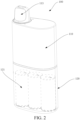
FIG. 2 is a schematic structural diagram of an electronic atomization device according to an embodiment of this application. -
FIG. 3 is a schematic structural diagram of an atomization cartridge chamber of the electronic atomization device shown inFIG. 1 separated from a body portion. -
FIG. 4 is a schematic structural cross-sectional view of an electronic atomization device according to an embodiment of this application. -
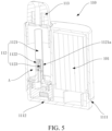
FIG. 5 is a schematic structural cross-sectional view of a body portion according to an embodiment of this application. -
FIG. 6 is a schematic structural diagram of an atomization core according to an embodiment of this application. -
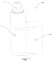
FIG. 7 is a schematic structural diagram of an electronic atomization device according to an embodiment of this application. - In the figures:
- 100. Electronic atomization device; 101. Battery;
- 110. Body portion; 111. Shell; 1111. Limiting step surface; 1112. Second air inlet hole; 112. Atomization core; 1121. Air tube; 1121a. Liquid inlet hole; 1122. Porous body; 1123. Heating net; 113. Suction nozzle;
- 120. Atomization cartridge chamber; 121. Atomization cartridge; 1211. Through hole; 1212. Housing; 1213. Top cover; 1214. Bottom cover; 1215. Liquid storage cotton; 122. Opening; 123. Convex rib; 124. First air inlet hole.
- For ease of understanding of this application, this application is described below in more detail with reference to accompanying drawings and specific implementations. The specific embodiments are merely used to explain this application, but not to limit this application. In addition, it needs to be further noted that, for ease of description, only part of the structure related to this application is shown in the accompanying drawings, but not the whole structure.
- Embodiments of this application provide an electronic atomization device. As shown in
FIG. 1 andFIG. 3 , anelectronic atomization device 100 includes abody portion 110 and anatomization cartridge chamber 120. Theatomization cartridge chamber 120 is detachably connected to thebody portion 110, which is specifically detachably connected to outside of thebody portion 110, and theatomization cartridge chamber 120 is configured to store astandby atomization cartridge 121. - Referring to
FIG. 4 , thebody portion 110 includes ashell 111 and abattery 101 arranged in theshell 111. As shown inFIG. 5 , a first accommodating space A is arranged in theshell 111, and the first accommodating space A is configured for theatomization cartridge 121 to be mounted. It may be understood that theatomization cartridge 121 may be mounted in theshell 111 before use, or may be taken out of theatomization cartridge chamber 120 and mounted in theshell 111 when in use, which is not limited herein. In other words, thebody portion 110 of this embodiment of this application may include theatomization cartridge 121, or may not include theatomization cartridge 121. As shown inFIG. 3 andFIG. 4 , a second accommodating space B for storing at least oneatomization cartridge 121 is arranged in theatomization cartridge chamber 120. The first accommodating space A is configured to removably receive the atomization cartridge from the second accommodating space B. Theelectronic atomization device 100 further includes anatomization core 112. A liquid substrate is stored in theatomization cartridge 121. Theatomization core 112 is configured to heat the liquid substrate to generate an aerosol, and thebattery 101 supplies power to theatomization core 112, so that theatomization core 112 heats the liquid substrate in theatomization cartridge 121 to form an aerosol. - The
atomization core 112 may be arranged in thebody portion 100 or in theatomization cartridge 121. In an embodiment, as shown inFIG. 4 , theatomization core 112 is arranged in thebody portion 110. Specifically, theatomization core 112 is arranged in theshell 111 of thebody portion 110, and theatomization core 112 can receive an electric power of thebattery 101 to heat the liquid substrate in theatomization cartridge 121 to form an aerosol. In another optional embodiment, theatomization core 112 may also be integrated in theatomization cartridge 121. Oneatomization core 112 is arranged in eachatomization cartridge 121. When theatomization cartridge 121 is mounted to theshell 111, theatomization core 112 may be electrically connected to thebattery 101, so that thebattery 101 supplies power to theatomization core 112. The liquid substrate may include mainly one or more of components such as glycerol, propylene glycol, a nicotine preparation, flavors and fragrances, and flavor additives. - In the
electronic atomization device 100 of this embodiment of this application, theatomization cartridge chamber 120 is detachably connected to thebody portion 110. To be specific, theatomization cartridge chamber 120 is detachably connected to the outside of thebody portion 110. Compared with the prior art in which the atomization cartridge chamber is arranged in the shell, theatomization cartridge chamber 120 in this embodiment of this application does not occupy the space in theshell 111, so that the volume of thebody portion 110 is relatively small. As shown inFIG. 3 , when thestandby atomization cartridge 121 is not needed, theatomization cartridge chamber 120 may be removed from thebody portion 110, and in this case, thebody portion 110 becomes an independent electronic atomization device with a small volume, and the electronic atomization device is compact, portable, and convenient to use. When both thebody portion 110 and thestandby atomization cartridge 121 need to be carried out, theatomization cartridge chamber 120 may be directly connected to thebody portion 110, so as to facilitate carrying and avoid causing scattered parts and inconvenience of carrying due to separation of theatomization cartridge chamber 120 from thebody portion 110. In addition, theatomization cartridge chamber 120 is connected to outside of thebody portion 110, so that the overall shape is novel and unique. - A housing of the
atomization cartridge chamber 120 may also be constructed to be at least partially transparent or semitransparent, so as to display theatomization cartridge 121 inside theatomization cartridge chamber 120. Referring toFIG. 3 , theatomization cartridge 121 in theatomization cartridge chamber 120 may be seen from the outside of theatomization cartridge chamber 120, so that the appearance of the entireelectronic atomization device 100 is more novel and more beautiful. It is preferable to arrange the entireatomization cartridge chamber 120 as a transparent structure, so that theatomization cartridge 121 in theatomization cartridge chamber 120 can be completely seen from the outside. Theatomization cartridge 121 may be set in various colors, and a plurality ofatomization cartridges 121 may be set in the same color or in different colors. Thecolorful atomization cartridges 121 in theatomization cartridge chamber 120 are seen from the outside of theatomization cartridge chamber 120, so as to greatly improve a visual effect. - Referring to
FIG. 3 andFIG. 4 , one ormore atomization cartridges 121 are stored in theatomization cartridge chamber 120. In a specific embodiment, referring toFIG. 4 , oneatomization cartridge 121 is mounted in thebody portion 110. Threeatomization cartridges 121 are stored in theatomization cartridge chamber 120. Each of theatomization cartridges 121 may be placed vertically in theatomization cartridge chamber 120, or may be placed horizontally in theatomization cartridge chamber 120. When theatomization cartridge 121 is placed horizontally in theatomization cartridge chamber 120, theatomization cartridges 121 may be successively stacked along a vertical direction. - The
atomization cartridge chamber 120 is detachably connected to thebody portion 110 in a number of manners. In an embodiment, theatomization cartridge chamber 120 can be removably connected to thebody portion 110 through engagement, insertion, or magnetic attraction. In the embodiment shown inFIG. 1 , theatomization cartridge chamber 120 is engaged onto thebody portion 110. In another optional embodiment, an insertion structure such as a slot may also be arranged between theatomization cartridge chamber 120 and thebody portion 110, to insert theatomization cartridge chamber 120 into thebody portion 110. - In an embodiment, as shown in
FIG. 1 , theatomization cartridge chamber 120 is connected to an end of thebody portion 110 along a longitudinal direction. In another optional embodiment, as shown inFIG. 7 , theatomization cartridge chamber 120 may also be connected to a side of thebody portion 110 along a transverse direction. Specifically, as shown inFIG. 1 , theatomization cartridge chamber 120 is engaged with the end of thebody portion 110 along the longitudinal direction. As shown inFIG. 7 , theatomization cartridge chamber 120 may also be engaged with a side of thebody portion 110 along a transverse direction. - Referring to
FIG. 3 , theshell 111 has a first end a and a second end b that are opposite along the longitudinal direction. The first end a is provided with asuction nozzle 113, and theatomization cartridge chamber 120 is detachably connected to the second end b. In other words, theatomization cartridge chamber 120 is arranged at an opposite end of thesuction nozzle 113, so as to prevent theatomization cartridge chamber 120 from interfering with thesuction nozzle 113, and ensure that a user can normally inhale the aerosol from thesuction nozzle 113. Specifically, the detachable connection between theatomization cartridge chamber 120 and the second end b is preferably engagement. - In an embodiment, as shown in
FIG. 3 , an end of theatomization cartridge chamber 120 connected to theshell 111 is provided with anopening 122, and theopening 122 is configured for theatomization cartridge 121 to be taken out from and placed into theatomization cartridge chamber 120. Theopening 122 is engaged with the second end b, so that theatomization cartridge chamber 120 is engaged with the second end b. The above structural design is not only convenient to take out and place theatomization cartridge 121 by using theopening 122, but also can be engaged with theshell 111 by using theopening 122, so that an engagement structure does not need to be separately designed, and the overall structure is simplified. - As shown in
FIG. 3 , the second end b of theshell 111 is provided with a limitingstep surface 1111, and an end of theatomization cartridge chamber 120 provided with theopening 122 abuts against the limitingstep surface 1111, to limit theatomization cartridge chamber 120. Specifically, as shown inFIG. 3 , theshell 111 includes two parts with different sizes which are adjacent to each other along the longitudinal direction. The part with a smaller size is close to theatomization cartridge chamber 120, and the limitingstep surface 1111 is formed between the two parts with different sizes. The limitingstep surface 1111 is an end surface of the larger part. Theatomization cartridge chamber 120 is engaged with the part with a smaller size and abuts against the end surface of the part with a larger size. - As shown in
FIG. 3 , an inner wall of theopening 122 of theatomization cartridge chamber 120 is provided with a verticalconvex rib 123. Theconvex rib 123 facilitates the engagement between theatomization cartridge chamber 120 and theshell 111, so that theatomization cartridge chamber 120 can be engaged with theshell 111 more tightly. - As described above, the first end a of the
shell 111 is provided with thesuction nozzle 113, and theatomization cartridge chamber 120 is engaged with the second end b of theshell 111. Referring toFIG. 4 , a bottom wall or a side wall of theatomization cartridge chamber 120 is provided with a firstair inlet hole 124, and the second end b of theshell 111 is provided with a secondair inlet hole 1112. In this way, an airflow channel extending through the secondair inlet hole 1112 from the firstair inlet hole 124 to thesuction nozzle 113 is formed in theelectronic atomization device 100. As shown inFIG. 4 , the firstair inlet hole 124 is preferably arranged on the bottom wall of theatomization cartridge chamber 120. - Referring to
FIG. 5 , theatomization core 112 is arranged in thebody portion 110. As shown inFIG. 5 andFIG. 6 , theatomization core 112 includes anair tube 1121, aporous body 1122, and aheating net 1123. As shown inFIG. 5 , theair tube 1121 is fixedly mounted in theshell 111, and theair tube 1121 is arranged along the longitudinal direction, so as to facilitate subsequent insertion of theatomization cartridge 121 into outside of theair tube 1121 along the longitudinal direction. As shown inFIG. 4 , a center of theatomization cartridge 121 is provided with a throughhole 1211 for theair tube 1121 to pass, and theair tube 1121 extends through the throughhole 1211 to assemble theatomization cartridge 121 with theatomization core 112. As shown inFIG. 6 , a side wall of theair tube 1121 is provided with aliquid inlet hole 1121a, and the liquid substrate in theatomization cartridge 121 enters theair tube 1121 through theliquid inlet hole 1121a. - As shown in
FIG. 5 , theporous body 1122 is arranged in theair tube 1121, and an outer surface of theporous body 1122 covers theliquid inlet hole 1121a, thereby receiving the liquid substrate entering theair tube 1121 through theliquid inlet hole 1121a. Theheating net 1123 is arranged in theporous body 1122, and theheating net 1123 is electrically connected to thebattery 101, so that thebattery 101 supplies power to theheating net 1123. Theheating net 1123 can heat the liquid substrate to form an aerosol after being electrified. The aerosol is outputted along theair tube 1121. Theporous body 1122 may be, for example, a porous ceramic or a porous member made of another material. - The structural design of the
atomization core 112 enables theatomization cartridge 121 to be directly inserted into theair tube 1121 of theatomization core 112, so as to facilitate installation and disassembly and replacement of theatomization cartridge 121. - Referring to
FIG. 4 , theatomization cartridge 121 includes ahousing 1212, atop cover 1213, abottom cover 1214, and aliquid storage cotton 1215. As shown inFIG. 4 , thehousing 1212 is cylindrical. Theliquid storage cotton 1215 is arranged in thehousing 1212, and theliquid storage cotton 1215 holds the liquid substrate. Thetop cover 1213 and thebottom cover 1214 respectively cover two ends of thehousing 1212 along the longitudinal direction, thereby fixing theliquid storage cotton 1215 in thehousing 1212. Thetop cover 1213, thebottom cover 1214, and theliquid storage cotton 1215 are all correspondingly provided with holes, thereby forming the throughhole 1211 in the center of theatomization cartridge 121. Theatomization cartridge 121 is inserted into theair tube 1121, so that the liquid substrate in theliquid storage cotton 1215 can enter theair tube 1121 through theliquid inlet hole 1121a on theair tube 1121 and be heated and atomized by theheating net 1123. The above structural design of theatomization cartridge 121 is convenient to mate with theatomization core 112, thereby realizing convenient and quick assembly and disassembly. - It is obvious that the above embodiments of this application are only for clearly describing the examples given by this application, and are not limitations on the implementations of this application. It is obvious to a person skilled in the art that various obvious changes, readjustments, and substitutions can be made without departing from the protection scope of this application. It is not necessary and impossible to exhaust all of the implementations herein.
Claims (11)
- An electronic atomization device (100), comprising:a body portion (110), comprising a shell (111) and a battery (101) arranged in the shell (111), wherein a first accommodating space is arranged in the shell (111);an atomization cartridge chamber (120), detachably connected to the body portion (110), wherein a second accommodating space for storing at least one atomization cartridge (121) is arranged in the atomization cartridge chamber (120), and a liquid substrate is stored in the atomization cartridge (121); andan atomization core (112), configured to heat the liquid substrate to generate an aerosol, whereinthe first accommodating space is configured to removably receive the atomization cartridge (121) from the second accommodating space, and the battery (101) supplies power to the atomization core (112), so that the atomization core (112) heats the liquid substrate in the atomization cartridge (121).
- The electronic atomization device (100) according to claim 1, wherein the atomization cartridge chamber (120) is engaged with, inserted into, or magnetically connected to the body portion (110).
- The electronic atomization device (100) according to claim 1, wherein the atomization cartridge chamber (120) is connected to an end of the body portion (110) along a longitudinal direction, or connected to a side of the body portion (110) along a transverse direction.
- The electronic atomization device (100) according to claim 1, wherein the shell (111) has a first end and a second end that are opposite along a longitudinal direction, the first end is provided with a suction nozzle (113), and the atomization cartridge chamber (120) is detachably connected to the second end.
- The electronic atomization device (100) according to claim 4, wherein an end of the atomization cartridge chamber (120) connected to the shell (111) is provided with an opening, the opening is configured for the atomization cartridge (121) to be taken out from and placed into the atomization cartridge chamber (120), and the opening is engaged with the second end, so that the atomization cartridge chamber (120) is engaged with the second end.
- The electronic atomization device (100) according to claim 5, wherein the second end of the shell (111) is provided with a limiting step surface (1111), and an end of the atomization cartridge chamber (120) provided with the opening abuts against the limiting step surface (1111) to limit the atomization cartridge chamber (120).
- The electronic atomization device (100) according to claim 4, wherein a bottom wall or a side wall of the atomization cartridge chamber (120) is provided with a first air inlet hole (124), and the second end is provided with a second air inlet hole (1112), so that an airflow channel extending through the second air inlet hole (1112) from the first air inlet hole (124) to the suction nozzle (113) is formed in the electronic atomization device (100).
- The electronic atomization device (100) according to claim 1, wherein the atomization core (112) is arranged in the body portion (110) or in the atomization cartridge (121).
- The electronic atomization device (100) according to claim 1, wherein the atomization core (112) is arranged in the body portion (110), and the atomization core comprises (112):an air tube (1121), arranged in the shell (111) along a longitudinal direction, wherein a liquid inlet hole (1121a) is provided on a side wall of the air tube (1121), a through hole (1211) is provided at a center of the atomization cartridge (121) for the air tube (1121) to pass, and the air tube (1121) extends through the through hole (1211) to fit the atomization cartridge (121) with the atomization core (112);a porous body (1122), arranged in the air tube (1121), wherein an outer surface of the porous body (1122) covers the liquid inlet hole (1121a); anda heating net (1123), arranged in the porous body (1122), wherein the heating net (1123) is electrically connected to the battery (101), so that the battery (101) supplies power to the heating net (1123).
- The electronic atomization device (100) according to claim 1, wherein the atomization cartridge (121) comprises:a cylindrical housing (1212); anda liquid storage cotton (1215), arranged in the cylindrical housing (1212), wherein the liquid storage cotton (1215) holds the liquid substrate.
- The electronic atomization device (100) according to any of claims 1 to 10, wherein a housing of the atomization cartridge chamber (120) is constructed to be at least partially transparent or semitransparent, so as to display the atomization cartridge (121) inside the atomization cartridge chamber (120).
Applications Claiming Priority (1)
| Application Number | Priority Date | Filing Date | Title |
|---|---|---|---|
| CN202321506435.4U CN220274919U (en) | 2023-06-13 | 2023-06-13 | Electronic atomization device |
Publications (1)
| Publication Number | Publication Date |
|---|---|
| EP4477098A1 true EP4477098A1 (en) | 2024-12-18 |
Family
ID=89330631
Family Applications (1)
| Application Number | Title | Priority Date | Filing Date |
|---|---|---|---|
| EP24181191.8A Pending EP4477098A1 (en) | 2023-06-13 | 2024-06-10 | Electronic atomization device |
Country Status (2)
| Country | Link |
|---|---|
| EP (1) | EP4477098A1 (en) |
| CN (1) | CN220274919U (en) |
Families Citing this family (1)
| Publication number | Priority date | Publication date | Assignee | Title |
|---|---|---|---|---|
| CN223008448U (en) * | 2024-07-31 | 2025-06-24 | 爱奇迹创造有限公司 | Heating non-combustion device and aerosol generating system |
Citations (3)
| Publication number | Priority date | Publication date | Assignee | Title |
|---|---|---|---|---|
| JP2012034666A (en) * | 2010-08-11 | 2012-02-23 | Tokyo Kinzoku Kogyo Kk | Smoking article |
| CN210203345U (en) * | 2019-05-21 | 2020-03-31 | 郑仁忠 | Slide rail type cigarette bullet replacing device |
| CN114343241A (en) * | 2021-12-23 | 2022-04-15 | 深圳市赛尔美电子科技有限公司 | Heating non-combustion device with self-locking and ejecting functions |
-
2023
- 2023-06-13 CN CN202321506435.4U patent/CN220274919U/en active Active
-
2024
- 2024-06-10 EP EP24181191.8A patent/EP4477098A1/en active Pending
Patent Citations (3)
| Publication number | Priority date | Publication date | Assignee | Title |
|---|---|---|---|---|
| JP2012034666A (en) * | 2010-08-11 | 2012-02-23 | Tokyo Kinzoku Kogyo Kk | Smoking article |
| CN210203345U (en) * | 2019-05-21 | 2020-03-31 | 郑仁忠 | Slide rail type cigarette bullet replacing device |
| CN114343241A (en) * | 2021-12-23 | 2022-04-15 | 深圳市赛尔美电子科技有限公司 | Heating non-combustion device with self-locking and ejecting functions |
Also Published As
| Publication number | Publication date |
|---|---|
| CN220274919U (en) | 2024-01-02 |
Similar Documents
| Publication | Publication Date | Title |
|---|---|---|
| CN215381432U (en) | Electronic atomization device and atomizer and gas-liquid balance element thereof | |
| CN211910517U (en) | Atomizers and Electronic Cigarettes | |
| JP7724961B2 (en) | Electronic atomization device and electronic atomization system | |
| EP3957196A1 (en) | Mixed-type heat-not-burn device and system | |
| JP7728972B2 (en) | Electronic atomization device and electronic atomization system | |
| CN109475184B (en) | Storage box | |
| JP2021083383A (en) | Power supply unit of aerosol generation device, body unit of aerosol generation device, aerosol generation device, and non-combustion type aspirator | |
| KR102227135B1 (en) | Cartomizer for electric heating type aerosol generator | |
| US12290099B2 (en) | Atomizing device and electronic cigarette | |
| CN215958321U (en) | Liquid storage unit, atomizer and electronic atomization device | |
| CN209090052U (en) | Electronic cigarette | |
| CN208875410U (en) | Electronic cigarette | |
| CN115053992A (en) | Can dismantle electron cigarette and electron cigarette group's accessory of retrieving battery | |
| CN220274919U (en) | Electronic atomization device | |
| CN206213288U (en) | Electronic cigarette | |
| CN210275916U (en) | e-cigarette | |
| TWI835403B (en) | Electronic cigarette stem and electronic cigarette | |
| CN219877469U (en) | Multi-taste electronic suction device | |
| CN217446709U (en) | Can dismantle electron cigarette and electron cigarette group's accessory of retrieving battery | |
| CN218457272U (en) | Electronic atomization system | |
| CN214483255U (en) | New electronic pod | |
| CN211431076U (en) | aerosol generating device | |
| CN223745791U (en) | Electronic atomizing device | |
| CN221929370U (en) | Charging device of electronic cigarette and electronic cigarette using charging device | |
| CN221382548U (en) | Atomizing device |
Legal Events
| Date | Code | Title | Description |
|---|---|---|---|
| PUAI | Public reference made under article 153(3) epc to a published international application that has entered the european phase |
Free format text: ORIGINAL CODE: 0009012 |
|
| STAA | Information on the status of an ep patent application or granted ep patent |
Free format text: STATUS: REQUEST FOR EXAMINATION WAS MADE |
|
| 17P | Request for examination filed |
Effective date: 20240610 |
|
| AK | Designated contracting states |
Kind code of ref document: A1 Designated state(s): AL AT BE BG CH CY CZ DE DK EE ES FI FR GB GR HR HU IE IS IT LI LT LU LV MC ME MK MT NL NO PL PT RO RS SE SI SK SM TR |