EP4477096A1 - Handheld aerosol generator, method of making an aerosol generating chamber of a handheld aerosol generator and method of making a handheld aerosol generator - Google Patents
Handheld aerosol generator, method of making an aerosol generating chamber of a handheld aerosol generator and method of making a handheld aerosol generator Download PDFInfo
- Publication number
- EP4477096A1 EP4477096A1 EP23179183.1A EP23179183A EP4477096A1 EP 4477096 A1 EP4477096 A1 EP 4477096A1 EP 23179183 A EP23179183 A EP 23179183A EP 4477096 A1 EP4477096 A1 EP 4477096A1
- Authority
- EP
- European Patent Office
- Prior art keywords
- coating
- container
- wall
- aerosol generator
- handheld
- Prior art date
- Legal status (The legal status is an assumption and is not a legal conclusion. Google has not performed a legal analysis and makes no representation as to the accuracy of the status listed.)
- Pending
Links
Images



Classifications
-
- A—HUMAN NECESSITIES
- A24—TOBACCO; CIGARS; CIGARETTES; SIMULATED SMOKING DEVICES; SMOKERS' REQUISITES
- A24F—SMOKERS' REQUISITES; MATCH BOXES; SIMULATED SMOKING DEVICES
- A24F40/00—Electrically operated smoking devices; Component parts thereof; Manufacture thereof; Maintenance or testing thereof; Charging means specially adapted therefor
- A24F40/40—Constructional details, e.g. connection of cartridges and battery parts
-
- A—HUMAN NECESSITIES
- A24—TOBACCO; CIGARS; CIGARETTES; SIMULATED SMOKING DEVICES; SMOKERS' REQUISITES
- A24F—SMOKERS' REQUISITES; MATCH BOXES; SIMULATED SMOKING DEVICES
- A24F40/00—Electrically operated smoking devices; Component parts thereof; Manufacture thereof; Maintenance or testing thereof; Charging means specially adapted therefor
- A24F40/20—Devices using solid inhalable precursors
Definitions
- the present invention relates to a handheld aerosol generator. It also relates to a method of making the aerosol generating chamber of a handheld aerosol generator and to a method of making a handheld aerosol generator.
- reduced-risk or modified-risk devices also known as vaporisers
- vaporisers Various devices and systems are available that heat or warm a substrate to product an aerosol as opposed to burning tobacco in conventional tobacco products.
- a commonly available reduced-risk or modified-risk device is a heated substrate aerosol generation device or heat-not-burn (HNB) device.
- HNB heat-not-burn
- Devices of this type generate an aerosol or vapor by heating an aerosol substrate (i.e., consumable) that typically comprises tobacco or other suitable aerosol material to a temperature typically in the range of 150°C to 350°C. Heating an aerosol substrate, but not combusting or burning it, releases an aerosol that comprises the core points sought by the user but not the undesirable by-products of combustion.
- the aerosol produced by heating the tobacco or other aerosol generating material does not typically comprise the burnt or bitter taste that may result from combustion.
- the aerosol substrate is generally inserted into a cup.
- the cup is arranged so that its interior can be accessed from the outside.
- the cup has on its periphery a means of heating the substrate. Using those means, the cup is capable transferring heat from the means of heating it to the material housed inside it. Accordingly, the material housed in the cup, that is, the consumable, is heated and thus vaporised. A user then inhales the vapour that is generated by the heating of the consumable.
- a stainless-steel material is typically used to make such cups. These cups have a thin film heater wrapped around the outside of the cup to heat up the stainless steel. The heat is then conducted to the consumable.
- j ⁇ refers to the total energy emitted per unit surface area of a black body across all wavelengths per unit time
- ⁇ is the Stefan-Boltzmann constant
- T is the temperature of the black body.
- the emissivity ⁇ is a number between 0 and 1 where 1 would be a perfect black body radiator of heat and 0 would be the opposite.
- the surface of the cup should have a value close to 1.
- stainless steel of grade 316L has a value of ⁇ of 0.26 which is unsatisfactory.
- the invention aims at alleviating or solving at least some of them.
- the invention is defined by the independent claims.
- a handheld aerosol generator is provided.
- Such a handheld aerosol generator is an aerosol generator that can be easily used when handheld and is, for example, distinct from aerosol generators such as shisha devices which are intended for standing on a table or the floor, rather than being handheld whilst in use.
- Such a handheld aerosol generator comprises a housing which will, when in use, be held by a user and which retains on its inside the container that can have the aerosol generating material disposed therein.
- the aerosol generating material can be introduced by a user. That is, the container is at least partially open to the surroundings.
- the container has an inner cavity surrounded by a wall, with the cavity being open to the surroundings of the handheld aerosol generator so that the aerosol generating material can be introduced into the cavity.
- the container has a surface treatment provided on the wall, preferably the inner surface of the wall.
- the treatment leads to an emissivity of 0.3 or larger.
- the treated surface has a higher emissivity than the untreated wall so that, as a consequence of the Stefan-Boltzmann law, the container is better at radiating heat and will thus heat up the aerosol generating material more quickly, in particular since the surface treatment is provided on the inner wall adjacent to the aerosol generating material.
- a heater is provided on the outside of the wall which can heat the wall of the container.
- the emissivity of the treated wall is increased, which leads to an improved absorption and/or emission of heat radiation. In consequence, this leads to a shortened time over which the aerosol generating substance is heated up: if the inner wall has the surface treatment applied thereto, it will radiate heat more efficiently to the aerosol generating material, which means that the aerosol generating material is heated up more quickly. If the outer surface has a surface treatment applied to it, a heat transfer to the cup from the outside (for example by a heater) is more efficient. These effects are particularly important for handheld devices which are typically driven by a limited capacity storage device for energy such as a battery.
- the surface treatment comprises the application of a coating which has a higher emissivity.
- Such coatings can be rather efficiently applied on surfaces so that corresponding handheld aerosol generators can be produced very cost efficiently.
- the coating has a thermal conductivity that is essentially the same as or higher than that of the material of the container. This ensures that the coating itself does not hinder heat transport within the container walls.
- the coating comprises and preferably consists of silicon carbide or aluminium nitride. Such coatings can be easily applied.
- the coating comprises a ceramic material.
- Such ceramic materials can also be easily applied and have a long service life.
- the coating comprises a hydrogenated amorphous silicon material.
- a hydrogenated amorphous silicon material are produced by SilcoTek as Silcolloy 1000 and have a glass-like behaviour. Such materials have a good heat radiation emission.
- a preferred embodiment involves that the surface treatment comprises a sandblasting and/or pickling surface treatment.
- Such treatments do not require the use of a separate material to be coated onto the surface and provide a way of making the otherwise shiny metal surfaces rougher and duller to improve thermal radiation absorbance.
- This pickled and/or sandblast surface can be oxidised which leads to an extremely inert and strong coating of the surface with better safety credentials.
- a treatment can, for example, in the case of a steel container be performed by placing the container in an oven which has a temperature of about 1000°C for about a week to create an oxide coating on the surface. Whilst this method leads the advantages mentioned previously, it is also comparatively slow, which leads to comparatively high costs and is thus less amenable to mass production. It is also possible to use an abrasive tool to scratch and dull the surface of the container or to dispense with any polishing steps. However, this comes with its own challenges in order to create a uniform surface within the container and also between different containers.
- the coating has a thickness of less than 2 ⁇ m.
- the coating should be as thin as possible since doing so reduces the time for the coating to be applied and also reduces the thickness of the material through which the heat to be transported so that the heat transfer efficiency is increased. Furthermore, for a particularly thin coating material, the heat conductivity is not that critical, given that there is very little material that is applied and that could impede heat transfer.
- a method of making an aerosol generating chamber of a handheld aerosol generator comprises providing a container which has an inner cavity surrounded by a wall.
- the cavity is open to the surroundings so that the aerosol generating material can be introduced into the cavity.
- the method further comprises the step of providing a treatment on a surface of the wall, preferably the inner surface, so that the treated surface has a higher emissivity than the untreated surface.
- any surface coating is applied to the wall using a CVD or a PVD method.
- Such methods of applying a coating are particularly easy to implement, for example using sputtering technologies, and have found applications in a wide range of industries.
- FIG. 1 illustrates an aerosol generator 100 according to an embodiment of the invention.
- the aerosol generator 100 is illustrated in the assembled configuration with the internal components arranged within a housing 50.
- the aerosol generator 100 is a heat-not-burn device, which may also be referred to as a tobacco-vapour device and comprises a container 200 configured to receive an aerosol substrate such as a rod of aerosol generating material, e.g., tobacco.
- the container 200 is operable to heat, but not burn, the rod of aerosol generating material to produce a vapour or aerosol for inhalation by a user.
- the aerosol generator 100 depicted in Figure 1 is simply an exemplary aerosol generator according to the invention. Other types and configurations of tobacco-vapour products, vaporisers, or electronic cigarettes may also be used as the aerosol generator according to the invention.
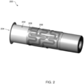
- FIG. 2 shows a container 200 according to an embodiment of the invention.
- the container 200 comprises a thermally conductive wall 202 which forms a cavity 214 configured to hold the aerosol generating material.
- the aerosol generating material can be introduced via an opening 204.
- the container 200 is tubular, e.g., cylindrical. In use, the user may insert the aerosol generating material through the opening 204 in the container 200 such that the aerosol generating material is positioned within the container 200 and interfaces with an inner surface 201 of the wall 202.
- the length of the wall 202 may be configured such that a portion of the aerosol generating material protrudes through the opening 204 (i.e., out of the cavity 214) and can be received in the mouth of the user for an experience akin to smoking a cigarette or similar product.
- the wall 202 is made of a material that allows for efficient heat transfer to the aerosol generating material while maintaining sufficient structural stability. Examples of such materials include steel or stainless steel.
- the container 200 is not limited to being tubular.
- the container 200 may be formed as a cuboidal, conical, hemi-spherical or other shaped cavity and can be configured to receive a complementary shaped aerosol generating material. Further, in some embodiments, the container 200 may not entirely surround the aerosol generating material but make instead only contact a limited area of the aerosol generating material.
- a coating 216 is applied on an inner surface 201 of the wall 202 .
- the coating 216 that is provided is a silcolloy coating produced by SilkoTek. This material improves emission of heat radiation to an aerosol generating material arranged in the cavity 214 of the container 200, with the heat produced by the heating element 208 of the thin film heater 207 provided so as to surround the wall 202.
- the thin film heater 207 comprises a heating element 208 that is mounted on a flexible backing film 210.
- the heating element 208 may comprise one or more heater tracks extending across a surface of the flexible backing film 210 which are insulated relative to the container 200 by means of an insulating layer 206.
- the heating element 208 comprises a heating material suitable for converting electrical energy into heat (such as stainless steel, titanium, nickel, nichrome, nickel-based alloys, silver, .
- a heating material suitable for converting electrical energy into heat such as stainless steel, titanium, nickel, nichrome, nickel-based alloys, silver, .
- power may be supplied to the heating element 208 from a power source such as a battery (not depicted) such that the temperature of the heating element 208 increases and heat energy is transferred across the insulating layer 206 to the wall 202.
- the aerosol generating material received within the container 200 is conductively heated by the wall 202 to produce an aerosol for inhalation by a user.
- the flexible backing film 210 comprises a flexible material preferably having a high dielectric capability and low thermal mass, such as polyamide or polyetheretherketon (PEEK).
- the thin film heater 207 is wrapped around the wall 200 in a circumferential direction such that the heating element 208 lies adjacent to (i.e., abuts, contacts) the layer 206. That is, the layer 206 acts as a separation between the heating element 208 and the wall 202 such that a contact between the heating element 208 and the wall 202 is prevented.
- the flexible backing film 210 lies on an opposing side of the heating element 208 to the layer 206, i.e., the heating element 208 is mounted to an inner surface of the flexible backing film 210 with respect to the cavity 200.
- the heating element 208 may not be formed as a thin film heater.
- the container 200 Due to the increased emissivity of the coating 216, the container 200 is better at radiating heat off to an aerosol generating material arranged inside the container 200, which thus improves the response time of the aerosol generator 100.
- Figure 4 illustrates a flowchart which is a method 300 of manufacturing an aerosol generating chamber of a handheld aerosol generator according to an embodiment of the invention.
- the method 300 begins at step 302, where a container into which an aerosol generating material can be introduced is provided.
- the container has an opening for receiving an aerosol generating material.
- a coating is applied onto an inner surface of the container using a PVD or CVD method. This can be done using vacuum deposition.
- the coating is deposited using chemical vapour deposition (CVD).
- CVD chemical vapour deposition
- the coating may be deposited using physical vapour deposition.
- step 306 a heating element is attached to the container, and finally, an electrically insulating film is wrapped around the container (step 308).
Landscapes
- Resistance Heating (AREA)
Abstract
The present invention relates to a handheld aerosol generator, comprising a housing, a container contained inside the housing and into which an aerosol generating material can be introduced by a user, the container having an inner cavity surrounded by a wall, the cavity being open to the surroundings so that the aerosol generating material can be introduced into the cavity, the container having a surface treatment provided on the outer surface of the wall so that the treated surface has a higher emissivity than the untreated wall, wherein the surface treatment preferably comprises a coating, a heater arranged to heat the treated wall of the container.
Description
- The present invention relates to a handheld aerosol generator. It also relates to a method of making the aerosol generating chamber of a handheld aerosol generator and to a method of making a handheld aerosol generator.
- The popularity and use of reduced-risk or modified-risk devices (also known as vaporisers) has grown rapidly in the past two years as an aid to assist habitual smokers wishing to quit using traditional tobacco products such as cigarettes, cigars, cigarillos, and rolling tobacco. Various devices and systems are available that heat or warm a substrate to product an aerosol as opposed to burning tobacco in conventional tobacco products.
- A commonly available reduced-risk or modified-risk device is a heated substrate aerosol generation device or heat-not-burn (HNB) device. Devices of this type generate an aerosol or vapor by heating an aerosol substrate (i.e., consumable) that typically comprises tobacco or other suitable aerosol material to a temperature typically in the range of 150°C to 350°C. Heating an aerosol substrate, but not combusting or burning it, releases an aerosol that comprises the core points sought by the user but not the undesirable by-products of combustion. In addition, the aerosol produced by heating the tobacco or other aerosol generating material does not typically comprise the burnt or bitter taste that may result from combustion.
- The aerosol substrate is generally inserted into a cup. The cup is arranged so that its interior can be accessed from the outside. The cup has on its periphery a means of heating the substrate. Using those means, the cup is capable transferring heat from the means of heating it to the material housed inside it. Accordingly, the material housed in the cup, that is, the consumable, is heated and thus vaporised. A user then inhales the vapour that is generated by the heating of the consumable.
- In the prior art, a stainless-steel material is typically used to make such cups. These cups have a thin film heater wrapped around the outside of the cup to heat up the stainless steel. The heat is then conducted to the consumable.
- Such a way of attaching and heating up the cup is rather effective for heat conduction. However, it is less effective for heat radiation, which is another significant method of heat transfer in particular to the aerosol generating substance. Thermal radiation can be expressed through the Stefan-Boltzmann law which contains a value ε for emissivity, that is

- Here, j ∗ refers to the total energy emitted per unit surface area of a black body across all wavelengths per unit time, σ is the Stefan-Boltzmann constant, and T is the temperature of the black body. The emissivity ε is a number between 0 and 1 where 1 would be a perfect black body radiator of heat and 0 would be the opposite. In order to have as efficient a heat transfer by thermal radiation as possible, the surface of the cup should have a value close to 1. However, stainless steel of grade 316L has a value of ε of 0.26 which is unsatisfactory.
- The invention aims at alleviating or solving at least some of them. The invention is defined by the independent claims.
- Preferred embodiments are set out in the respective dependent claims.
- According to claim 1, a handheld aerosol generator is provided. Such a handheld aerosol generator is an aerosol generator that can be easily used when handheld and is, for example, distinct from aerosol generators such as shisha devices which are intended for standing on a table or the floor, rather than being handheld whilst in use.
- Such a handheld aerosol generator comprises a housing which will, when in use, be held by a user and which retains on its inside the container that can have the aerosol generating material disposed therein. Into the container, the aerosol generating material can be introduced by a user. That is, the container is at least partially open to the surroundings.
- The container has an inner cavity surrounded by a wall, with the cavity being open to the surroundings of the handheld aerosol generator so that the aerosol generating material can be introduced into the cavity. The container has a surface treatment provided on the wall, preferably the inner surface of the wall. The treatment leads to an emissivity of 0.3 or larger. As a consequence, the treated surface has a higher emissivity than the untreated wall so that, as a consequence of the Stefan-Boltzmann law, the container is better at radiating heat and will thus heat up the aerosol generating material more quickly, in particular since the surface treatment is provided on the inner wall adjacent to the aerosol generating material. Furthermore, a heater is provided on the outside of the wall which can heat the wall of the container.
- By the surface treatment, the emissivity of the treated wall is increased, which leads to an improved absorption and/or emission of heat radiation. In consequence, this leads to a shortened time over which the aerosol generating substance is heated up: if the inner wall has the surface treatment applied thereto, it will radiate heat more efficiently to the aerosol generating material, which means that the aerosol generating material is heated up more quickly. If the outer surface has a surface treatment applied to it, a heat transfer to the cup from the outside (for example by a heater) is more efficient. These effects are particularly important for handheld devices which are typically driven by a limited capacity storage device for energy such as a battery. Compared with fixedly installed devices, such as shisha devices, which can be connected to a main electricity supply, energy efficiency is much more important. Furthermore, having a higher absorption capability for heat radiation and a quicker heating up capability of the aerosol generating substance allows for a quicker response time. This improves the user friendliness.
- It is to be noted that whilst in the above, we have focused on the inner surface of the wall having the surface treatment and, to a lesser extent, on the outer surface having the surface treatment applied to it, it is most likely the case that all wall surfaces have the surface treatment applied to it to simplify manufacture.
- It is preferred that the surface treatment comprises the application of a coating which has a higher emissivity. Such coatings can be rather efficiently applied on surfaces so that corresponding handheld aerosol generators can be produced very cost efficiently.
- It is preferred that the coating has a thermal conductivity that is essentially the same as or higher than that of the material of the container. This ensures that the coating itself does not hinder heat transport within the container walls.
- In a preferred embodiment, the coating comprises and preferably consists of silicon carbide or aluminium nitride. Such coatings can be easily applied.
- It is also preferred if the coating comprises a ceramic material. Such ceramic materials can also be easily applied and have a long service life.
- It is also preferred that the coating comprises a hydrogenated amorphous silicon material. Such materials are produced by SilcoTek as Silcolloy 1000 and have a glass-like behaviour. Such materials have a good heat radiation emission.
- Additionally, a preferred embodiment involves that the surface treatment comprises a sandblasting and/or pickling surface treatment. Such treatments do not require the use of a separate material to be coated onto the surface and provide a way of making the otherwise shiny metal surfaces rougher and duller to improve thermal radiation absorbance.
- This pickled and/or sandblast surface can be oxidised which leads to an extremely inert and strong coating of the surface with better safety credentials. Such a treatment can, for example, in the case of a steel container be performed by placing the container in an oven which has a temperature of about 1000°C for about a week to create an oxide coating on the surface. Whilst this method leads the advantages mentioned previously, it is also comparatively slow, which leads to comparatively high costs and is thus less amenable to mass production. It is also possible to use an abrasive tool to scratch and dull the surface of the container or to dispense with any polishing steps. However, this comes with its own challenges in order to create a uniform surface within the container and also between different containers.
- It is preferred that the coating has a thickness of less than 2 µm. The coating should be as thin as possible since doing so reduces the time for the coating to be applied and also reduces the thickness of the material through which the heat to be transported so that the heat transfer efficiency is increased. Furthermore, for a particularly thin coating material, the heat conductivity is not that critical, given that there is very little material that is applied and that could impede heat transfer.
- According to another aspect of the invention, a method of making an aerosol generating chamber of a handheld aerosol generator is claimed. The method comprises providing a container which has an inner cavity surrounded by a wall. The cavity is open to the surroundings so that the aerosol generating material can be introduced into the cavity.
- The method further comprises the step of providing a treatment on a surface of the wall, preferably the inner surface, so that the treated surface has a higher emissivity than the untreated surface. This leads to the effects mentioned previously.
- It is particularly preferred that any surface coating is applied to the wall using a CVD or a PVD method. Such methods of applying a coating are particularly easy to implement, for example using sputtering technologies, and have found applications in a wide range of industries.
-
-
Figure 1 shows an aerosol generator according to a first embodiment of the invention. -
Figure 2 shows a schematic cross-sectional view of an aerosol generating chamber according to the invention. -
Figure 3 shows a cross-sectional view of a heating chamber according to an embodiment of the invention. -
Figure 4 shows a flow diagram showing method steps for manufacturing the heating chamber according to an embodiment of the invention. -
Figure 1 illustrates anaerosol generator 100 according to an embodiment of the invention. Theaerosol generator 100 is illustrated in the assembled configuration with the internal components arranged within ahousing 50. - The
aerosol generator 100 is a heat-not-burn device, which may also be referred to as a tobacco-vapour device and comprises acontainer 200 configured to receive an aerosol substrate such as a rod of aerosol generating material, e.g., tobacco. Thecontainer 200 is operable to heat, but not burn, the rod of aerosol generating material to produce a vapour or aerosol for inhalation by a user. Of course, the skilled person will appreciate that theaerosol generator 100 depicted inFigure 1 is simply an exemplary aerosol generator according to the invention. Other types and configurations of tobacco-vapour products, vaporisers, or electronic cigarettes may also be used as the aerosol generator according to the invention. -
Figure 2 shows acontainer 200 according to an embodiment of the invention. Thecontainer 200 comprises a thermallyconductive wall 202 which forms acavity 214 configured to hold the aerosol generating material. The aerosol generating material can be introduced via anopening 204. Thecontainer 200 is tubular, e.g., cylindrical. In use, the user may insert the aerosol generating material through theopening 204 in thecontainer 200 such that the aerosol generating material is positioned within thecontainer 200 and interfaces with aninner surface 201 of thewall 202. The length of thewall 202 may be configured such that a portion of the aerosol generating material protrudes through the opening 204 (i.e., out of the cavity 214) and can be received in the mouth of the user for an experience akin to smoking a cigarette or similar product. - The
wall 202 is made of a material that allows for efficient heat transfer to the aerosol generating material while maintaining sufficient structural stability. Examples of such materials include steel or stainless steel. The skilled person will appreciate that thecontainer 200 is not limited to being tubular. For example, thecontainer 200 may be formed as a cuboidal, conical, hemi-spherical or other shaped cavity and can be configured to receive a complementary shaped aerosol generating material. Further, in some embodiments, thecontainer 200 may not entirely surround the aerosol generating material but make instead only contact a limited area of the aerosol generating material. - According to the invention, a
coating 216 is applied on aninner surface 201 of thewall 202 . Thecoating 216 that is provided is a silcolloy coating produced by SilkoTek. This material improves emission of heat radiation to an aerosol generating material arranged in thecavity 214 of thecontainer 200, with the heat produced by theheating element 208 of thethin film heater 207 provided so as to surround thewall 202. Thethin film heater 207 comprises aheating element 208 that is mounted on aflexible backing film 210. Theheating element 208 may comprise one or more heater tracks extending across a surface of theflexible backing film 210 which are insulated relative to thecontainer 200 by means of an insulatinglayer 206. Theheating element 208 comprises a heating material suitable for converting electrical energy into heat (such as stainless steel, titanium, nickel, nichrome, nickel-based alloys, silver, . In use, power may be supplied to theheating element 208 from a power source such as a battery (not depicted) such that the temperature of theheating element 208 increases and heat energy is transferred across the insulatinglayer 206 to thewall 202. The aerosol generating material received within thecontainer 200 is conductively heated by thewall 202 to produce an aerosol for inhalation by a user. - The
flexible backing film 210 comprises a flexible material preferably having a high dielectric capability and low thermal mass, such as polyamide or polyetheretherketon (PEEK). Thethin film heater 207 is wrapped around thewall 200 in a circumferential direction such that theheating element 208 lies adjacent to (i.e., abuts, contacts) thelayer 206. That is, thelayer 206 acts as a separation between theheating element 208 and thewall 202 such that a contact between theheating element 208 and thewall 202 is prevented. Theflexible backing film 210 lies on an opposing side of theheating element 208 to thelayer 206, i.e., theheating element 208 is mounted to an inner surface of theflexible backing film 210 with respect to thecavity 200. The skilled person will appreciate that, in alternative embodiments, theheating element 208 may not be formed as a thin film heater. - Due to the increased emissivity of the
coating 216, thecontainer 200 is better at radiating heat off to an aerosol generating material arranged inside thecontainer 200, which thus improves the response time of theaerosol generator 100. -
Figure 4 illustrates a flowchart which is amethod 300 of manufacturing an aerosol generating chamber of a handheld aerosol generator according to an embodiment of the invention. - The
method 300 begins atstep 302, where a container into which an aerosol generating material can be introduced is provided. The container has an opening for receiving an aerosol generating material. - At
step 304, a coating is applied onto an inner surface of the container using a PVD or CVD method. This can be done using vacuum deposition. Preferably, the coating is deposited using chemical vapour deposition (CVD). However, in some examples, the coating may be deposited using physical vapour deposition. - Subsequently, in
step 306, a heating element is attached to the container, and finally, an electrically insulating film is wrapped around the container (step 308).
Claims (15)
- Handheld aerosol generator (100), comprising:- a housing (50),- a container (200) contained inside the housing (50) for receiving aerosol generating material, the container (200) having an inner cavity (214) surrounded by a wall (202), the cavity (214) being open to the surroundings for receiving aerosol generating material, the container (200) having a surface treatment provided on a surface (203) of the wall (202) so that the treated surface has a higher emissivity than the untreated wall (202), wherein the emissivity of the treated wall is higher than 0.3, wherein the surface treatment preferably comprises a coating (216),- a heater (207) arranged to heat the treated surface of the container (200).
- Handheld aerosol generator (100) according to claim 1, wherein the surface treatment is provided on the inner and/or outer surface of the wall (202).
- Handheld aerosol generator (100) according to claim 1 or 2, wherein the coating (216) comprises, preferably consists of, SiC and/or AlN and/or wherein the coating (216) comprises a ceramic material.
- Handheld aerosol generator (100) according to one of claims 1 to 2, wherein the coating (216) comprises a hydrogenated amorphous silicon material.
- Handheld aerosol generator (100) according to one of claims 1 to 2, wherein the surface treatment comprises a sandblasting and/or pickling surface treatment, wherein preferably, the sandblasted and/or pickled surface has been oxidised.
- Handheld aerosol generator (100) according to one of claims 1 to 5, wherein the coating (216) has a thickness of less than 2 µm.
- Handheld aerosol generator (100) according to one of the preceding claims, wherein the coating (216) has a thermal conductivity that is essentially the same as or higher than that of the material of the container (200).
- Method of making the aerosol generating chamber of a handheld aerosol generator (100), the method comprising:- providing a container (200) into which an aerosol generating material can be introduced, the container (200) having an inner cavity (214) surrounded by a wall (202), the cavity (214) being open to the surroundings so that the aerosol generating material can be introduced into the cavity (214),- providing a treatment on a surface of the wall (202) so that the treated surface has a higher emissivity than the untreated surface and has an emissivity higher than 0.3, wherein the surface treatment preferably includes the application of a coating (216).
- Method according to claim 8, wherein the inner and/or outer surface of the wall (202) are treated.
- Method according to claim 8 or 9, wherein the coating (216) has a thermal conductivity that is essentially the same as or higher than that of the material of the container (200) and/or wherein the coating (216) is applied to the wall (202) using a CVD or a PVD method.
- Method according to claim 10, wherein the coating (216) is a hydrogenated amorphous silicon material or wherein the coating (216) comprises, preferably consists of, SiC and/or AlN.
- Method according to one of claims 8 to 11, wherein the coating (216) comprises a ceramic material.
- Method according to one of claims 8 to 10, wherein the outer surface of the wall (202) is treated by sandblasting and/or picking, wherein the outer surface is preferably subjected to an oxidisation treatment.
- Method according to one of claims 8 to 13, wherein the coating (216) has a thickness of less than 2 pm.
- Method of making a handheld aerosol generator (100), comprising providing an aerosol generating chamber (200) that has been made using the method of one of claims 8 to 14 and arranging the aerosol generating chamber (200) inside a housing (50) .
Priority Applications (1)
| Application Number | Priority Date | Filing Date | Title |
|---|---|---|---|
| EP23179183.1A EP4477096A1 (en) | 2023-06-14 | 2023-06-14 | Handheld aerosol generator, method of making an aerosol generating chamber of a handheld aerosol generator and method of making a handheld aerosol generator |
Applications Claiming Priority (1)
| Application Number | Priority Date | Filing Date | Title |
|---|---|---|---|
| EP23179183.1A EP4477096A1 (en) | 2023-06-14 | 2023-06-14 | Handheld aerosol generator, method of making an aerosol generating chamber of a handheld aerosol generator and method of making a handheld aerosol generator |
Publications (1)
| Publication Number | Publication Date |
|---|---|
| EP4477096A1 true EP4477096A1 (en) | 2024-12-18 |
Family
ID=86776351
Family Applications (1)
| Application Number | Title | Priority Date | Filing Date |
|---|---|---|---|
| EP23179183.1A Pending EP4477096A1 (en) | 2023-06-14 | 2023-06-14 | Handheld aerosol generator, method of making an aerosol generating chamber of a handheld aerosol generator and method of making a handheld aerosol generator |
Country Status (1)
| Country | Link |
|---|---|
| EP (1) | EP4477096A1 (en) |
Citations (3)
| Publication number | Priority date | Publication date | Assignee | Title |
|---|---|---|---|---|
| US20220095684A1 (en) * | 2019-03-22 | 2022-03-31 | Nerudia Limited | Smoking Substitute System |
| EP4091486A1 (en) * | 2020-01-17 | 2022-11-23 | Shenzhen First Union Technology Co., Ltd. | Heating device |
| CN115381142A (en) * | 2022-08-03 | 2022-11-25 | 深圳麦时科技有限公司 | Heating element, atomizer and aerosol generating device |
-
2023
- 2023-06-14 EP EP23179183.1A patent/EP4477096A1/en active Pending
Patent Citations (3)
| Publication number | Priority date | Publication date | Assignee | Title |
|---|---|---|---|---|
| US20220095684A1 (en) * | 2019-03-22 | 2022-03-31 | Nerudia Limited | Smoking Substitute System |
| EP4091486A1 (en) * | 2020-01-17 | 2022-11-23 | Shenzhen First Union Technology Co., Ltd. | Heating device |
| CN115381142A (en) * | 2022-08-03 | 2022-11-25 | 深圳麦时科技有限公司 | Heating element, atomizer and aerosol generating device |
Similar Documents
| Publication | Publication Date | Title |
|---|---|---|
| JP7731402B2 (en) | Aerosol generating device and heating chamber therefor | |
| JP7600448B2 (en) | Aerosol generating device and heating chamber therefor | |
| CN112822951B (en) | Aerosol generating device and heating chamber thereof | |
| US12465085B2 (en) | Aerosol-generating device with heating coating | |
| JP2025143323A (en) | Aerosol generating device and heating chamber therefor | |
| EP4566469A1 (en) | Heating assembly, atomizer and aerosol generating apparatus | |
| US20250082027A1 (en) | Heating Chamber Assembly for an Aerosol Generation Device | |
| JP7549741B2 (en) | Aerosol generator with insulating heater | |
| EP4362724B1 (en) | Heating assembly for aerosol generating device | |
| US20250049122A1 (en) | Heating Chamber Assembly for an Aerosol Generation Device | |
| EP4287878B1 (en) | Heating chamber for an aerosol generating device | |
| EP4544936A1 (en) | Aerosol generating device, heater for aerosol generating device, and control method | |
| JP7815258B2 (en) | Heating assembly for an aerosol generating device | |
| CN222941803U (en) | Aerosol generating device and heater for aerosol generating device | |
| EP4728826A1 (en) | Heating assembly for an aerosol generating device and associated method for obtaining said heating assembly | |
| WO2024227799A1 (en) | Aerosol generating device comprising a 3d printed ceramic cup and associated method for producing | |
| EP4633398A1 (en) | Aerosol generating device with a vacuum insulator |
Legal Events
| Date | Code | Title | Description |
|---|---|---|---|
| PUAI | Public reference made under article 153(3) epc to a published international application that has entered the european phase |
Free format text: ORIGINAL CODE: 0009012 |
|
| STAA | Information on the status of an ep patent application or granted ep patent |
Free format text: STATUS: THE APPLICATION HAS BEEN PUBLISHED |
|
| AK | Designated contracting states |
Kind code of ref document: A1 Designated state(s): AL AT BE BG CH CY CZ DE DK EE ES FI FR GB GR HR HU IE IS IT LI LT LU LV MC ME MK MT NL NO PL PT RO RS SE SI SK SM TR |
|
| STAA | Information on the status of an ep patent application or granted ep patent |
Free format text: STATUS: REQUEST FOR EXAMINATION WAS MADE |
|
| 17P | Request for examination filed |
Effective date: 20250611 |