EP4475642A1 - Slide rail assembly - Google Patents
Slide rail assembly Download PDFInfo
- Publication number
- EP4475642A1 EP4475642A1 EP24150510.6A EP24150510A EP4475642A1 EP 4475642 A1 EP4475642 A1 EP 4475642A1 EP 24150510 A EP24150510 A EP 24150510A EP 4475642 A1 EP4475642 A1 EP 4475642A1
- Authority
- EP
- European Patent Office
- Prior art keywords
- rail
- handle
- bracket
- slide rail
- supporting feature
- Prior art date
- Legal status (The legal status is an assumption and is not a legal conclusion. Google has not performed a legal analysis and makes no representation as to the accuracy of the status listed.)
- Granted
Links
Images






Classifications
-
- F—MECHANICAL ENGINEERING; LIGHTING; HEATING; WEAPONS; BLASTING
- F16—ENGINEERING ELEMENTS AND UNITS; GENERAL MEASURES FOR PRODUCING AND MAINTAINING EFFECTIVE FUNCTIONING OF MACHINES OR INSTALLATIONS; THERMAL INSULATION IN GENERAL
- F16C—SHAFTS; FLEXIBLE SHAFTS; ELEMENTS OR CRANKSHAFT MECHANISMS; ROTARY BODIES OTHER THAN GEARING ELEMENTS; BEARINGS
- F16C29/00—Bearings for parts moving only linearly
- F16C29/02—Sliding-contact bearings
-
- A—HUMAN NECESSITIES
- A47—FURNITURE; DOMESTIC ARTICLES OR APPLIANCES; COFFEE MILLS; SPICE MILLS; SUCTION CLEANERS IN GENERAL
- A47B—TABLES; DESKS; OFFICE FURNITURE; CABINETS; DRAWERS; GENERAL DETAILS OF FURNITURE
- A47B88/00—Drawers for tables, cabinets or like furniture; Guides for drawers
- A47B88/40—Sliding drawers; Slides or guides therefor
- A47B88/483—Sliding drawers; Slides or guides therefor with single extensible guides or parts
-
- H—ELECTRICITY
- H05—ELECTRIC TECHNIQUES NOT OTHERWISE PROVIDED FOR
- H05K—PRINTED CIRCUITS; CASINGS OR CONSTRUCTIONAL DETAILS OF ELECTRIC APPARATUS; MANUFACTURE OF ASSEMBLAGES OF ELECTRICAL COMPONENTS
- H05K7/00—Constructional details common to different types of electric apparatus
- H05K7/14—Mounting supporting structure in casing or on frame or rack
- H05K7/1485—Servers; Data center rooms, e.g. 19-inch computer racks
- H05K7/1488—Cabinets therefor, e.g. chassis or racks or mechanical interfaces between blades and support structures
- H05K7/1489—Cabinets therefor, e.g. chassis or racks or mechanical interfaces between blades and support structures characterized by the mounting of blades therein, e.g. brackets, rails, trays
-
- A—HUMAN NECESSITIES
- A47—FURNITURE; DOMESTIC ARTICLES OR APPLIANCES; COFFEE MILLS; SPICE MILLS; SUCTION CLEANERS IN GENERAL
- A47B—TABLES; DESKS; OFFICE FURNITURE; CABINETS; DRAWERS; GENERAL DETAILS OF FURNITURE
- A47B2210/00—General construction of drawers, guides and guide devices
- A47B2210/0002—Guide construction for drawers
- A47B2210/0018—Buffers, stop blocks or latches for single drawer slides
Definitions
- the present invention is related to a slide rail assembly with a handle.
- US publication number US 2022/0369478 A1 discloses a handle module arranged on a server. Furthermore, the handle module comprises a handle having a sliding column assembly.
- the sliding column assembly is pivotally arranged relative to a plate member and movable relative to the plate member.
- the plate member comprises two plates stacked one above the other. Each of the plates is provided with holes in different directions for mounting the sliding column assembly. With such arrangement, a user can push the handle to mount the server in a rack.
- the present invention aims at providing a slide rail assembly with a supporting feature and a handle.
- the claimed slide rail assembly comprises a first rail, a bracket, a supporting feature, a second rail and a handle.
- the bracket is arranged on the first rail.
- the supporting feature is arranged on one of the bracket and the first rail.
- the second rail is movable relative to the first rail.
- the handle is movable relative to the second rail. When the handle is moved from a first operating position to a second operating position, the handle is configured to contact the supporting feature in order to drive the second rail to move from a first predetermined position to a second predetermined position relative to the first rail.
- a slide rail assembly 20 comprises a first rail 22, a bracket 24, a supporting feature 26, a second rail 28 and a handle 30 according to a first embodiment of the present invention.
- the slide rail assembly 20 further comprises a third rail 32 (such as a middle rail) movably mounted between the first rail 22 (such as an outer rail) and the second rail 28 (such as an inner rail), and the third rail 32 is configured to extend a longitudinal moving distance of the second rail 28 relative to the first rail 22.
- the X axis is a longitudinal direction (or a length direction or moving direction of the slide rail)
- the Y axis is a transverse direction (or a lateral direction of the slide rail)
- the Z axis is a vertical direction (or a height direction of the slide rail).
- the bracket 24 is arranged on the first rail 22, and the first rail 22 is configured to be mounted to at least one post (such as a first post 36a and a second post 36b) of a rack 34 through the bracket 24.
- the bracket 24 has a first side L1 and a second side L2 opposite to each other.
- the first side L1 of the bracket 24 is configured to be mounted to at least one corresponding feature (such as a mounting hole) of the rack 34 through at least one mounting feature 38 (such as an extension part, a bolt or the like as shown in FIG. 2 ).
- Such configuration is well known to those skilled in the art, for simplification, no further illustration is provided.
- the second side L2 of the bracket 24 is connected to a first side (such as a back side) of the first rail 22, but the present invention is not limited thereto.
- the third rail 32 and the second rail 28 are located on a second side of the first rail 22.
- the bracket 24 is connected (such as fixedly connected) to the first rail 22, the bracket 24 can be seen as a part of the first rail 22, or the bracket 24 and the first rail 22 can be seen as one piece.
- the supporting feature 26 is arranged on one of the first rail 22 and the second rail 28.
- the supporting feature 26 is arranged on the bracket 24 of the first rail 22, but the present invention is not limited thereto.
- the bracket 24 has a first end part 24a (such as a front end part) and a second end part 24b (such as a rear end part) opposite to each other.
- the supporting feature 26 is adjacent to the first end part 24a of the bracket 24.
- the second rail 28 is configured to be located at a first predetermined position P1 (such as a retracted position as shown in FIG. 1 , but the present invention is not limited thereto) relative to the first rail 22.
- the handle 30 is movable relative to the first rail 22 and the second rail 28. In the first embodiment, the handle 30 is movably mounted on the second rail 28.
- the supporting feature 26 is fixed to one of the bracket 24 and the first rail 22.
- the supporting feature 26 is fixed to the bracket 24.
- the supporting feature 26 is a protrusion, and the supporting feature 26 can be an additional part fixed to the bracket 24; or the supporting feature 26 can be directly integrated onto the bracket 24, but the present invention is not limited thereto.
- the first rail 22 has a first predetermined height H1.
- the bracket 24 comprises a first part 42a, a second part 42b and a longitudinal part 44 connected between the first part 42a and the second part 42b of the bracket 24.
- a second predetermined height H2 is defined between the first part 42a and the second part 42b of the bracket 24 and is greater than the first predetermined height H1 (as shown in FIG. 1 ).
- the bracket 24 is connected to the first rail 22 through the longitudinal part 44.
- the supporting feature 26 is arranged on the longitudinal part 44 of the bracket 24, and the supporting feature 26 is located adjacent to the second part 42b of the bracket 24.
- the supporting feature 26 is located adjacent to the first end part 24a of the bracket 24.
- the second rail 28 comprises a first wall 46a, a second wall 46b and a longitudinal wall 48 connected between the first wall 46a and the second wall 46b of the second rail 28.
- the second rail 28 has a first end part 28a and a second end part 28b opposite to each other.
- the handle 30 is movably mounted on the longitudinal wall 48 of the second rail 28.
- the handle 30 is pivotally connected to the longitudinal wall 48 of the second rail 28 through a shaft member 40, and the handle 30 is adjacent to the first end part 28a (such as a front end part) of the second rail 28 for convenience of a user.
- the handle 30 comprises an operating part 50, a corresponding part 52 and a main body part 54 connected between the operating part 50 and the corresponding part 52. At least one portion of the operating part 50 exceeds (or is higher than) the first rail 22.
- the corresponding part 52 is configured to interact with the supporting feature 26.
- the main body part 54 is pivotally connected to the longitudinal wall 48 of the second rail 28 through the shaft member 40.
- the shaft member 40 is arranged on the longitudinal wall 48 of the second rail 28 transversely (or in a lateral direction of the slide rail, that is, the Y-axis direction), such that the user can easily move the handle 30 through the operating part 50.
- the corresponding part 52 of the handle 30 comprises a first corresponding section 56 and a second corresponding section 58, and a predetermined space S is defined between the second corresponding section 58 and the first corresponding section 56.
- the second rail 28 is located at the first predetermined position P1 relative to the first rail 22 and when the handle 30 is located at a first operating position K1 (such as an initial position or a position before being operated), the supporting feature 26 is located in the predetermined space S.
- the handle 30 is configured to contact the supporting feature 26, in order to drive the second rail 28 to move away from the first predetermined position P1 along an opening direction D1 (as shown in FIG. 3 ) .
- the second rail 28 is driven to move from the first predetermined position P1 to a second predetermined position P2 (as shown in FIG. 4 ).
- the handle 30 is configured to continuously contact the supporting feature 26 through the first corresponding section 56 to generate an acting force, such that the second rail 28 is configured to be moved relative to the first rail 22 from the first predetermined position P1 (as shown in FIG. 3 ) to the second predetermined position P2 (as shown in FIG. 4 ) along the opening direction D1 in response to the acting force.
- the user can easily open the second rail 28 from the first predetermined position P1 to the second predetermined position P2.
- the second rail 28 carries a carried object (such as electronic device, not shown figures), and when the carried object has a loading weight or an electronic plug (or socket) behind the carried object is required to be unplugged from a predetermined device or a predetermined power source, the user can use the handle 30 to open the second rail 28 from the first predetermined position P1 to the second predetermined position P2 with less effort.
- the first corresponding section 56 of the handle 30 has an inclined surface or an arc surface.
- the handle 30 can easily cross the support feature 26 through the first corresponding section 56.
- the second corresponding section 58 of the handle 30 has a wall (such as a vertical wall, but the present invention is not limited thereto) .
- the handle 30 continuously contacts the supporting feature 26 through the first corresponding section 56 to generate another acting force, such that the handle 30 is moved from the second operating position K2 back to the first operating position K1.
- FIG. 5 and FIG. 6 are diagrams showing a slide rail assembly 200 according to a second embodiment of the present invention.
- a supporting feature 202 of the slide rail assembly 200 of the second embodiment is movably mounted to one of a bracket 204 and a first rail 206.
- the supporting feature 202 is movably mounted to the bracket 204, but the present invention is not limited thereto.
- the bracket 204 is configured to be mounted to a rack 207.
- the supporting feature 202 can be a roller, a ball or the like.
- the supporting feature 202 is a roller.
- the supporting feature 202 is pivotally connected to a longitudinal part 210 of the bracket 204 through an auxiliary shaft 208, such that the supporting feature 202 is pivoted relative to the bracket 204.
- the supporting feature 202 comprises a guiding section 212.
- the guiding section 212 has an arc surface.
- the supporting feature 202 has a circular profile to provide the arc surface.
- the handle 214 is configured to contact the supporting feature 202 in order to drive the second rail 216 to move from a first predetermined position P1' (as shown in FIG. 5 ) to a second predetermined position P2' (as shown in FIG. 6 ).
- the handle 214 is configured to continuously contact the supporting feature 202 through a first corresponding section 218 to generate an acting force, such that the second rail 216 is configured to be moved relative to the first rail 206 from the first predetermined position P1' (as shown in FIG. 5 ) to the second predetermined position P2' (as shown in FIG. 6 ) along the opening direction D1 in response to the acting force. Therefore, the second embodiment can achieve substantially the same technical effect as that of the first embodiment.
- the supporting feature 202 can be a movable (such as rotatable) roller.
- the handle 214 is moved from the first operating position K1' to the second operating position K2', and when the first corresponding section 218 of the handle 214 contacts the supporting feature 202, the supporting feature 202 is configured to be rotated along a predetermined working direction r through the auxiliary shaft 208 (as shown in FIG. 6 , the predetermined working direction r is counterclockwise, but the present invention is not limited thereto), such that it is easier to move the handle 214 from the first operating position K1' to the second operating position K2' .
- the handle 214 can be operated with less effort.
- FIG. 7 and FIG. 8 are diagrams showing a slide rail assembly 300 according to a third embodiment of the present invention.
- a second rail 302 of the slide rail assembly 300 of the third embodiment is configured to carry a carried object 304, and a handle 306 is movably mounted to the carried object 304.
- the handle 306 is pivotally connected to the carried object 304 through a shaft member 308, but the present invention is not limited thereto.
- the carried object 304 is fixed on the second rail 302, such that the carried object 304 can be seen as a part of the second rail 302, or the carried object 304 and the second rail 302 can be seen as one piece.
- the handle 306 is configured to contact the supporting feature 310, in order to drive the second rail 302 (and the carried object 304) to move from a first predetermined position Pa (as shown in FIG. 7 ) to a second predetermined position Pb (as shown in FIG. 8 ).
- the handle 306 is configured to continuously contact the supporting feature 310 through the first corresponding section 312 to generate an acting force, such that the second rail 302 is configured to be moved relative to the first rail 314 from the first predetermined position Pa (as shown in FIG. 7 ) to the second predetermined position Pb (as shown in FIG. 8 ) along the opening direction D1. Therefore, the third embodiment can achieve substantially the same technical effect as that of the first embodiment. For example, the user can move the second rail 302 (and the carried object 304) from the first predetermined position Pa to the second predetermined position Pb with less effort through the handle 306.
- FIG. 9 and FIG. 10 are diagrams showing a slide rail assembly 400 according to a fourth embodiment of the present invention.
- a second rail 402 of a slide rail assembly 400 of the fourth embodiment is configured to carry a carried object 404, and a handle 406 is movably mounted to the carried object 404.
- the handle 306 is pivotally connected to the carried object 404 through a shaft member 408, but the present invention is not limited thereto.
- the carried object 404 is fixed on the second rail 402, such that the carried object 404 can be seen as a part of the second rail 402, or the carried object 404 and the second rail 402 can be seen as one piece.
- the handle 406 is configured to contact a supporting feature 410, in order to drive the second rail 402 (and the carried object 404) to move from a first predetermined position Pa' (as shown in FIG. 9 ) to a second predetermined position Pb' (as shown in FIG. 10 ) .
- the handle 406 is configured to continuously contact the supporting feature 410 through the first corresponding section 412 to generate an acting force, such that the second rail 402 is configured to be moved relative to the first rail 414 from the first predetermined position Pa' (as shown in FIG. 9 ) to the second predetermined position Pb' (as shown in FIG. 10 ) along the opening direction D1. Therefore, the fourth embodiment can achieve substantially the same technical effect as that of the second embodiment.
- the supporting feature 410 can be a movable (rotatable) roller.
- the supporting feature 410 is configured to rotated along a predetermined working direction r' through an auxiliary shaft 416 (as shown in FIG. 10 ), such that it is easier to move the handle 406 from the first operating position Ka' to the second operating position Kb'.
- the handle 214 can be operated with less effort.
- the slide rail assembly according to the embodiments of the present invention has the following technical features:
Landscapes
- Engineering & Computer Science (AREA)
- General Engineering & Computer Science (AREA)
- Computer Hardware Design (AREA)
- Microelectronics & Electronic Packaging (AREA)
- Mechanical Engineering (AREA)
- Seats For Vehicles (AREA)
- Drawers Of Furniture (AREA)
Abstract
Description
- The present invention is related to a slide rail assembly with a handle.
- US publication number
US 2022/0369478 A1 discloses a handle module arranged on a server. Furthermore, the handle module comprises a handle having a sliding column assembly. The sliding column assembly is pivotally arranged relative to a plate member and movable relative to the plate member. The plate member comprises two plates stacked one above the other. Each of the plates is provided with holes in different directions for mounting the sliding column assembly. With such arrangement, a user can push the handle to mount the server in a rack. - However, in order to meet diverse requirements of the market, it is important to develop various products.
- This in mind, the present invention aims at providing a slide rail assembly with a supporting feature and a handle.
- This is achieved by a slide rail assembly according to claim 1. The dependent claims pertain to corresponding further developments and improvements.
- As will be seen more clearly from the detailed description following below, the claimed slide rail assembly comprises a first rail, a bracket, a supporting feature, a second rail and a handle. The bracket is arranged on the first rail. The supporting feature is arranged on one of the bracket and the first rail. The second rail is movable relative to the first rail. The handle is movable relative to the second rail. When the handle is moved from a first operating position to a second operating position, the handle is configured to contact the supporting feature in order to drive the second rail to move from a first predetermined position to a second predetermined position relative to the first rail.
- In the following, the invention is further illustrated by way of example, taking reference to the accompanying drawings thereof:
-
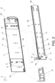
FIG. 1 is diagram showing a slide rail assembly being mounted to a rack according to a first embodiment of the present invention; -
FIG. 2 is an exploded view of the slide rail assembly according to the first embodiment of the present invention; -
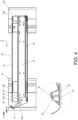
FIG. 3 is a diagram showing a second rail of the slide rail assembly being located at a first predetermined position relative to a first rail according to the first embodiment of the present invention; -
FIG. 4 is a diagram showing a handle being operated to drive the second rail to move to a second predetermined position according to the first embodiment of the present invention; -
FIG. 5 is a diagram showing a slide rail assembly being mounted to the rack according to a second embodiment of the present invention; -
FIG. 6 is a diagram showing a handle being operated to drive a second rail to move to a second predetermined position according to the second embodiment of the present invention; -
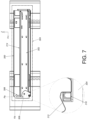
FIG. 7 is a diagram showing a slide rail assembly being mounted to the rack with a second rail being configured to carry a carried object according to a third embodiment of the present invention; -
FIG. 8 is a diagram showing a handle being operated to drive the second rail and the carried object to move to the second predetermined position according to the third embodiment of the present invention; -
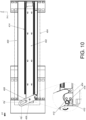
FIG. 9 is a diagram showing a slide rail assembly being mounted to the rack with a second rail being configured to carry a carried object according to a fourth embodiment of the present invention; and -
FIG. 10 is a diagram showing a handle being operated to drive the second rail and the carried object to move to the second predetermined position according to the fourth embodiment of the present invention. - As shown in
FIG. 1 andFIG. 2 , aslide rail assembly 20 comprises afirst rail 22, abracket 24, a supportingfeature 26, asecond rail 28 and ahandle 30 according to a first embodiment of the present invention. Preferably, theslide rail assembly 20 further comprises a third rail 32 (such as a middle rail) movably mounted between the first rail 22 (such as an outer rail) and the second rail 28 (such as an inner rail), and thethird rail 32 is configured to extend a longitudinal moving distance of thesecond rail 28 relative to thefirst rail 22. In the present embodiment, the X axis is a longitudinal direction (or a length direction or moving direction of the slide rail), the Y axis is a transverse direction (or a lateral direction of the slide rail), and the Z axis is a vertical direction (or a height direction of the slide rail). - The
bracket 24 is arranged on thefirst rail 22, and thefirst rail 22 is configured to be mounted to at least one post (such as afirst post 36a and asecond post 36b) of arack 34 through thebracket 24. In the present embodiment, thebracket 24 has a first side L1 and a second side L2 opposite to each other. The first side L1 of thebracket 24 is configured to be mounted to at least one corresponding feature (such as a mounting hole) of therack 34 through at least one mounting feature 38 (such as an extension part, a bolt or the like as shown inFIG. 2 ). Such configuration is well known to those skilled in the art, for simplification, no further illustration is provided. The second side L2 of thebracket 24 is connected to a first side (such as a back side) of thefirst rail 22, but the present invention is not limited thereto. Thethird rail 32 and thesecond rail 28 are located on a second side of thefirst rail 22. Moreover, since thebracket 24 is connected (such as fixedly connected) to thefirst rail 22, thebracket 24 can be seen as a part of thefirst rail 22, or thebracket 24 and thefirst rail 22 can be seen as one piece. - The supporting
feature 26 is arranged on one of thefirst rail 22 and thesecond rail 28. In the present embodiment, the supportingfeature 26 is arranged on thebracket 24 of thefirst rail 22, but the present invention is not limited thereto. Thebracket 24 has afirst end part 24a (such as a front end part) and asecond end part 24b (such as a rear end part) opposite to each other. The supportingfeature 26 is adjacent to thefirst end part 24a of thebracket 24. - The
second rail 28 is configured to be located at a first predetermined position P1 (such as a retracted position as shown inFIG. 1 , but the present invention is not limited thereto) relative to thefirst rail 22. - The
handle 30 is movable relative to thefirst rail 22 and thesecond rail 28. In the first embodiment, thehandle 30 is movably mounted on thesecond rail 28. - Preferably, in the first embodiment, the supporting
feature 26 is fixed to one of thebracket 24 and thefirst rail 22. For example, the supportingfeature 26 is fixed to thebracket 24. Furthermore, the supportingfeature 26 is a protrusion, and the supportingfeature 26 can be an additional part fixed to thebracket 24; or the supportingfeature 26 can be directly integrated onto thebracket 24, but the present invention is not limited thereto. - Preferably, the
first rail 22 has a first predetermined height H1. Thebracket 24 comprises afirst part 42a, asecond part 42b and alongitudinal part 44 connected between thefirst part 42a and thesecond part 42b of thebracket 24. A second predetermined height H2 is defined between thefirst part 42a and thesecond part 42b of thebracket 24 and is greater than the first predetermined height H1 (as shown inFIG. 1 ). - Preferably, the
bracket 24 is connected to thefirst rail 22 through thelongitudinal part 44. - Preferably, the supporting
feature 26 is arranged on thelongitudinal part 44 of thebracket 24, and the supportingfeature 26 is located adjacent to thesecond part 42b of thebracket 24. - Preferably, the supporting
feature 26 is located adjacent to thefirst end part 24a of thebracket 24. - Preferably, the
second rail 28 comprises afirst wall 46a, asecond wall 46b and alongitudinal wall 48 connected between thefirst wall 46a and thesecond wall 46b of thesecond rail 28. On the other hand, thesecond rail 28 has afirst end part 28a and asecond end part 28b opposite to each other. Thehandle 30 is movably mounted on thelongitudinal wall 48 of thesecond rail 28. For example, thehandle 30 is pivotally connected to thelongitudinal wall 48 of thesecond rail 28 through ashaft member 40, and thehandle 30 is adjacent to thefirst end part 28a (such as a front end part) of thesecond rail 28 for convenience of a user. - Preferably, the
handle 30 comprises anoperating part 50, acorresponding part 52 and amain body part 54 connected between theoperating part 50 and thecorresponding part 52. At least one portion of theoperating part 50 exceeds (or is higher than) thefirst rail 22. Thecorresponding part 52 is configured to interact with the supportingfeature 26. Themain body part 54 is pivotally connected to thelongitudinal wall 48 of thesecond rail 28 through theshaft member 40. - Preferably, the
shaft member 40 is arranged on thelongitudinal wall 48 of thesecond rail 28 transversely (or in a lateral direction of the slide rail, that is, the Y-axis direction), such that the user can easily move thehandle 30 through the operatingpart 50. - As shown in
FIG. 3 , thecorresponding part 52 of thehandle 30 comprises a firstcorresponding section 56 and a secondcorresponding section 58, and a predetermined space S is defined between the secondcorresponding section 58 and the firstcorresponding section 56. When thesecond rail 28 is located at the first predetermined position P1 relative to thefirst rail 22 and when thehandle 30 is located at a first operating position K1 (such as an initial position or a position before being operated), the supportingfeature 26 is located in the predetermined space S. - As shown in
FIG. 3 andFIG. 4 , during a process of moving thehandle 30 from the first operating position K1 (as shown inFIG. 3 ) to a second operating position K2 (a non-initial position or a position after being operated as shown inFIG. 4 ), thehandle 30 is configured to contact the supportingfeature 26, in order to drive thesecond rail 28 to move away from the first predetermined position P1 along an opening direction D1 (as shown inFIG. 3 ) . For example, thesecond rail 28 is driven to move from the first predetermined position P1 to a second predetermined position P2 (as shown inFIG. 4 ). - For example, during a process of the user applying a force on the handle 30 (the operating
portion 50 of the handle 30) to move thehandle 30 from the first operating position K1 (as shown inFIG. 3 ) to the second operating position K2 (as shown inFIG. 4 ) along a predetermined rotation direction R, thehandle 30 is configured to continuously contact the supportingfeature 26 through the firstcorresponding section 56 to generate an acting force, such that thesecond rail 28 is configured to be moved relative to thefirst rail 22 from the first predetermined position P1 (as shown inFIG. 3 ) to the second predetermined position P2 (as shown inFIG. 4 ) along the opening direction D1 in response to the acting force. Therefore, the user can easily open thesecond rail 28 from the first predetermined position P1 to the second predetermined position P2. For example, when thesecond rail 28 carries a carried object (such as electronic device, not shown figures), and when the carried object has a loading weight or an electronic plug (or socket) behind the carried object is required to be unplugged from a predetermined device or a predetermined power source, the user can use thehandle 30 to open thesecond rail 28 from the first predetermined position P1 to the second predetermined position P2 with less effort. - Preferably, the first
corresponding section 56 of thehandle 30 has an inclined surface or an arc surface. Thereby, during the processing of moving thehandle 30 from the first operating position K1 to the second operating position K2, thehandle 30 can easily cross thesupport feature 26 through the firstcorresponding section 56. On the other hand, the secondcorresponding section 58 of thehandle 30 has a wall (such as a vertical wall, but the present invention is not limited thereto) . - Moreover, when the
second rail 28 is moved relative to thefirst rail 22 from the second predetermined position P2 (as shown inFIG. 4 ) along a retracting direction D2 to the first predetermined position P1 (as shown inFIG. 3 ), thehandle 30 continuously contacts the supportingfeature 26 through the firstcorresponding section 56 to generate another acting force, such that thehandle 30 is moved from the second operating position K2 back to the first operating position K1. -
FIG. 5 andFIG. 6 are diagrams showing aslide rail assembly 200 according to a second embodiment of the present invention. Different from theslide rail assembly 20 of the first embodiment, a supportingfeature 202 of theslide rail assembly 200 of the second embodiment is movably mounted to one of abracket 204 and afirst rail 206. In the present embodiment, the supportingfeature 202 is movably mounted to thebracket 204, but the present invention is not limited thereto. - Furthermore, the
bracket 204 is configured to be mounted to arack 207. The supportingfeature 202 can be a roller, a ball or the like. In the present embodiment, the supportingfeature 202 is a roller. For example, the supportingfeature 202 is pivotally connected to alongitudinal part 210 of thebracket 204 through anauxiliary shaft 208, such that the supportingfeature 202 is pivoted relative to thebracket 204. Preferably, the supportingfeature 202 comprises aguiding section 212. The guidingsection 212 has an arc surface. In the present embodiment, the supportingfeature 202 has a circular profile to provide the arc surface. - During a processing of moving the
handle 214 from a first operating position K1' (as shown inFIG. 5 ) to a second operating position K2' (as shown inFIG. 6 ) along a predetermined rotation direction R' through ashaft member 215, thehandle 214 is configured to contact the supportingfeature 202 in order to drive thesecond rail 216 to move from a first predetermined position P1' (as shown inFIG. 5 ) to a second predetermined position P2' (as shown inFIG. 6 ). For example, during a process of the user applying a force on thehandle 214 to move thehandle 214 from the first operating position K1' to the second operating position K2', thehandle 214 is configured to continuously contact the supportingfeature 202 through a firstcorresponding section 218 to generate an acting force, such that thesecond rail 216 is configured to be moved relative to thefirst rail 206 from the first predetermined position P1' (as shown inFIG. 5 ) to the second predetermined position P2' (as shown inFIG. 6 ) along the opening direction D1 in response to the acting force. Therefore, the second embodiment can achieve substantially the same technical effect as that of the first embodiment. - Moreover, in the second embodiment, the supporting
feature 202 can be a movable (such as rotatable) roller. When thehandle 214 is moved from the first operating position K1' to the second operating position K2', and when the firstcorresponding section 218 of thehandle 214 contacts the supportingfeature 202, the supportingfeature 202 is configured to be rotated along a predetermined working direction r through the auxiliary shaft 208 (as shown inFIG. 6 , the predetermined working direction r is counterclockwise, but the present invention is not limited thereto), such that it is easier to move thehandle 214 from the first operating position K1' to the second operating position K2' . For the user, thehandle 214 can be operated with less effort. -
FIG. 7 andFIG. 8 are diagrams showing aslide rail assembly 300 according to a third embodiment of the present invention. Different from theslide rail assembly 20 of the first embodiment, asecond rail 302 of theslide rail assembly 300 of the third embodiment is configured to carry a carriedobject 304, and ahandle 306 is movably mounted to the carriedobject 304. In the present embodiment, thehandle 306 is pivotally connected to the carriedobject 304 through ashaft member 308, but the present invention is not limited thereto. Moreover, the carriedobject 304 is fixed on thesecond rail 302, such that the carriedobject 304 can be seen as a part of thesecond rail 302, or the carriedobject 304 and thesecond rail 302 can be seen as one piece. - During a process of moving the
handle 306 from a first operating position Ka (as shown inFIG. 7 ) to a second operating position Kb (as shown inFIG. 8 ) along a predetermined rotation direction, thehandle 306 is configured to contact the supportingfeature 310, in order to drive the second rail 302 (and the carried object 304) to move from a first predetermined position Pa (as shown inFIG. 7 ) to a second predetermined position Pb (as shown inFIG. 8 ). For example, during a process of the user applying a force on thehandle 306 to move thehandle 306 from the first operating position Ka to the second operating position Kb, thehandle 306 is configured to continuously contact the supportingfeature 310 through the firstcorresponding section 312 to generate an acting force, such that thesecond rail 302 is configured to be moved relative to thefirst rail 314 from the first predetermined position Pa (as shown inFIG. 7 ) to the second predetermined position Pb (as shown inFIG. 8 ) along the opening direction D1. Therefore, the third embodiment can achieve substantially the same technical effect as that of the first embodiment. For example, the user can move the second rail 302 (and the carried object 304) from the first predetermined position Pa to the second predetermined position Pb with less effort through thehandle 306. -
FIG. 9 andFIG. 10 are diagrams showing aslide rail assembly 400 according to a fourth embodiment of the present invention. Different from theslide rail assembly 200 of the second embodiment, asecond rail 402 of aslide rail assembly 400 of the fourth embodiment is configured to carry a carriedobject 404, and ahandle 406 is movably mounted to the carriedobject 404. In the present embodiment, thehandle 306 is pivotally connected to the carriedobject 404 through ashaft member 408, but the present invention is not limited thereto. Moreover, the carriedobject 404 is fixed on thesecond rail 402, such that the carriedobject 404 can be seen as a part of thesecond rail 402, or the carriedobject 404 and thesecond rail 402 can be seen as one piece. - During a process of moving the
handle 406 from a first operating position Ka' (as shown inFIG. 9 ) to a second operating position Kb' (as shown inFIG. 10 ) along a predetermined rotation direction, thehandle 406 is configured to contact a supportingfeature 410, in order to drive the second rail 402 (and the carried object 404) to move from a first predetermined position Pa' (as shown inFIG. 9 ) to a second predetermined position Pb' (as shown inFIG. 10 ) . For example, during a process of the user applying a force on thehandle 406 to move thehandle 406 from the first operating position Ka' to the second operating position Kb', thehandle 406 is configured to continuously contact the supportingfeature 410 through the firstcorresponding section 412 to generate an acting force, such that thesecond rail 402 is configured to be moved relative to thefirst rail 414 from the first predetermined position Pa' (as shown inFIG. 9 ) to the second predetermined position Pb' (as shown inFIG. 10 ) along the opening direction D1. Therefore, the fourth embodiment can achieve substantially the same technical effect as that of the second embodiment. - Moreover, in the fourth embodiment, the supporting
feature 410 can be a movable (rotatable) roller. When thehandle 406 is moved from the first operating position Ka' to the second operating position Kb', and when the firstcorresponding section 412 of thehandle 406 contacts the supportingfeature 410, the supportingfeature 410 is configured to rotated along a predetermined working direction r' through an auxiliary shaft 416 (as shown inFIG. 10 ), such that it is easier to move thehandle 406 from the first operating position Ka' to the second operating position Kb'. For the user, thehandle 214 can be operated with less effort. - Therefore, the slide rail assembly according to the embodiments of the present invention has the following technical features:
- 1. Through arrangement of the handle (30, 214, 306, 406) and the supporting feature (26, 202, 310, 410), the user can easily or effortlessly move the slide rail (such as the
second rail - 2. The supporting feature (26, 310) is fixed relative to the first rail (22, 206, 314, 414) and the bracket (24, 204); or the supporting feature (202, 410) is movable (such as rotatable) relative to the first rail (22, 206, 314, 414) and the bracket (24, 204). For example, the supporting feature (202, 410) is movable, such that it is easier to move the handle (214, 406) from the first operating position (K1', Ka') to the second operating position (K2', Kb').
- 3. The handle (30, 214) is movably mounted on the second rail (28, 216); or the handle (306, 406) is movably mounted on the carried object (304, 404).
Claims (15)
- A slide rail assembly (20, 200, 300, 400), comprising:a first rail (22, 206, 314, 414);a bracket (24, 204) arranged on the first rail (22, 206, 314, 414);a supporting feature (26, 202, 310, 410) arranged on one of the bracket (24, 204) and the first rail (22, 206, 314, 414);a second rail (28, 216, 302, 402) movable relative to the first rail (22, 206, 314, 414); andcharacterized by:a handle (30, 214, 306, 406) movable relative to the second rail (28, 216, 302, 402);wherein when the handle (30, 214, 306, 406) is moved from a first operating position to a second operating position, the handle (30, 214, 306, 406) is configured to contact the supporting feature (26, 202, 310, 410) in order to drive the second rail (28, 216, 302, 402) to move from a first predetermined position to a second predetermined position relative to the first rail (22, 206, 314, 414) .
- The slide rail assembly of claim 1, characterized in that the handle (30, 214, 306, 406) is pivoted to the second rail (28, 216, 302, 402).
- The slide rail assembly of claim 1 or 2, characterized in that the second rail (302, 402) is configured to carry a carried object (304, 404), and the handle (306, 406) is pivoted to the carried object (304, 404).
- The slide rail assembly of any of claims 1-3, characterized in that the supporting feature (26, 310) is fixed to one of the bracket (24) and the first rail (22, 314).
- The slide rail assembly of any of claims 1-4, characterized in that the supporting feature (202, 410) is movably mounted to one of the bracket (204) and the first rail (206, 414).
- The slide rail assembly of claim 5, characterized in that the supporting feature (202, 410) is a roller.
- The slide rail assembly of claim 5 or 6, characterized in that the supporting feature (202, 410) comprises a guiding section (212) .
- The slide rail assembly of claim 7, characterized in that the guiding section (212) has an arc surface.
- The slide rail assembly of any of claims 1-8, characterized in that the handle (30, 214, 306, 406) comprises a first corresponding section (56, 218, 312, 412); wherein during a process of moving the handle (30, 214, 306, 406) from the first operating position to the second operating position, the handle (30, 214, 306, 406) is configured to continuously contact the supporting feature (26, 202, 310, 410) through the first corresponding section (56, 218, 312, 412) in order to drive the second rail (28, 216, 302, 402) to move from the first predetermined position to the second predetermined position relative to the first rail (22, 206, 314, 414).
- The slide rail assembly of claim 9, characterized in that the handle (30, 214, 306, 406) further comprises a second corresponding section (58), and a predetermined space is defined between the second corresponding section (58) and the first corresponding section (56, 218, 312, 412); wherein when the second rail (28, 216, 302, 402) is located at the first predetermined position and when the handle (30, 214, 306, 406) is located at the first operating position, the supporting feature (26, 202, 310, 410) is located in the predetermined space.
- The slide rail assembly of any of claims 1-10, characterized in that the first rail (22, 206, 314, 414) is configured to be mounted to a rack (34, 207) through the bracket (24, 204).
- The slide rail assembly of any of claims 1-11, characterized in that the first rail (22, 206, 314, 414) has a first predetermined height, the bracket (24, 204) comprises a first part (42a), a second part (42b) and a longitudinal part (44, 210) connected between the first part (42a) and the second part (42b), and the first part (42a) and the second part (42b) of the bracket (24, 204) define a second predetermined height greater than the first predetermined height.
- The slide rail assembly of claim 12, characterized in that the longitudinal part (44, 210) of the bracket (24, 204) is connected to the first rail (22, 206, 314, 414).
- The slide rail assembly of claim 12 or 13, characterized in that the second rail (28, 216) comprises a first wall (46a), a second wall (46b) and a longitudinal wall (48) connected between the first wall (46a) and the second wall (46b) ; wherein the handle (30, 214) is movably mounted on the longitudinal wall (48) of the second rail (28, 216).
- The slide rail assembly of claim 14, characterized in that the supporting feature (26, 202) is arranged on the longitudinal part (44, 210) of the bracket (24, 204), and the supporting feature (26, 202) is adjacent to one of the first part (42a) and the second part (42b) of the bracket (24, 204).
Applications Claiming Priority (1)
| Application Number | Priority Date | Filing Date | Title |
|---|---|---|---|
| TW112121765A TWI842561B (en) | 2023-06-08 | 2023-06-08 | Slide rail assembly |
Publications (2)
| Publication Number | Publication Date |
|---|---|
| EP4475642A1 true EP4475642A1 (en) | 2024-12-11 |
| EP4475642B1 EP4475642B1 (en) | 2025-04-16 |
Family
ID=89509048
Family Applications (1)
| Application Number | Title | Priority Date | Filing Date |
|---|---|---|---|
| EP24150510.6A Active EP4475642B1 (en) | 2023-06-08 | 2024-01-05 | Slide rail assembly |
Country Status (4)
| Country | Link |
|---|---|
| US (1) | US12454977B2 (en) |
| EP (1) | EP4475642B1 (en) |
| JP (2) | JP2024177046A (en) |
| TW (1) | TWI842561B (en) |
Families Citing this family (2)
| Publication number | Priority date | Publication date | Assignee | Title |
|---|---|---|---|---|
| US20230054055A1 (en) * | 2022-09-22 | 2023-02-23 | Intel Corporation | Mounting adaptor assemblies to support memory devices in server systems |
| TWI847910B (en) * | 2023-11-09 | 2024-07-01 | 川湖科技股份有限公司 | Slide rail assembly |
Citations (3)
| Publication number | Priority date | Publication date | Assignee | Title |
|---|---|---|---|---|
| US20180116068A1 (en) * | 2016-10-24 | 2018-04-26 | Wistron Corporation | Handle locking device and electronic system having the same |
| US20190174642A1 (en) * | 2017-12-01 | 2019-06-06 | Seagate Technology Llc | Adjustable carrier |
| US20220369478A1 (en) | 2021-05-14 | 2022-11-17 | Wiwynn Corporation | Handle module, server, and server system |
Family Cites Families (7)
| Publication number | Priority date | Publication date | Assignee | Title |
|---|---|---|---|---|
| US3039837A (en) | 1960-01-08 | 1962-06-19 | Hartwell Corp | Latching device |
| US6560114B2 (en) * | 2001-06-29 | 2003-05-06 | Intel Corporation | Rack-mounted server and associated methods |
| WO2014209334A1 (en) * | 2013-06-28 | 2014-12-31 | Hewlett-Packard Development Company, L.P. | Lever unit |
| TWI594711B (en) * | 2016-05-31 | 2017-08-11 | 川湖科技股份有限公司 | Slide rail device |
| TWI659712B (en) * | 2018-04-02 | 2019-05-21 | 川湖科技股份有限公司 | Slide rail assembly |
| TWI659710B (en) * | 2018-04-02 | 2019-05-21 | 川湖科技股份有限公司 | Slide rail assembly |
| US11197389B2 (en) * | 2020-04-06 | 2021-12-07 | Super Micro Computer Inc. | Server chassis |
-
2023
- 2023-06-08 TW TW112121765A patent/TWI842561B/en active
- 2023-10-26 US US18/495,003 patent/US12454977B2/en active Active
-
2024
- 2024-01-05 EP EP24150510.6A patent/EP4475642B1/en active Active
- 2024-01-09 JP JP2024000958A patent/JP2024177046A/en active Pending
-
2025
- 2025-11-27 JP JP2025205549A patent/JP2026064987A/en active Pending
Patent Citations (3)
| Publication number | Priority date | Publication date | Assignee | Title |
|---|---|---|---|---|
| US20180116068A1 (en) * | 2016-10-24 | 2018-04-26 | Wistron Corporation | Handle locking device and electronic system having the same |
| US20190174642A1 (en) * | 2017-12-01 | 2019-06-06 | Seagate Technology Llc | Adjustable carrier |
| US20220369478A1 (en) | 2021-05-14 | 2022-11-17 | Wiwynn Corporation | Handle module, server, and server system |
Also Published As
| Publication number | Publication date |
|---|---|
| US12454977B2 (en) | 2025-10-28 |
| EP4475642B1 (en) | 2025-04-16 |
| TWI842561B (en) | 2024-05-11 |
| JP2026064987A (en) | 2026-04-14 |
| JP2024177046A (en) | 2024-12-19 |
| US20240410421A1 (en) | 2024-12-12 |
| TW202450392A (en) | 2024-12-16 |
Similar Documents
| Publication | Publication Date | Title |
|---|---|---|
| EP4475642B1 (en) | Slide rail assembly | |
| EP3352546A1 (en) | Slide rail assembly | |
| EP3513681B1 (en) | Furniture system and slide rail assembly thereof | |
| EP3644695A1 (en) | Slide rail assembly | |
| EP3253188A1 (en) | Slide rail assembly | |
| EP3637968A1 (en) | Cable management assembly | |
| US20200346265A1 (en) | Bending Machine and Method for Bending a Workpiece Out of a Flat Material | |
| EP4401520A1 (en) | Slide rail assembly | |
| EP4548808A1 (en) | Slide rail assembly | |
| KR101558102B1 (en) | Mandrel for square pipe bendings that have flap and slide plate | |
| CN214184680U (en) | Angle-adjustable bending mechanism of thermoforming machine | |
| EP3419397B1 (en) | Slide rail assembly | |
| JP2613746B2 (en) | Straightener | |
| JP6620410B2 (en) | Projector support device | |
| EP1161359A1 (en) | Device for holding and contacting a radiotelephone | |
| CN220219173U (en) | A mobile frame structure | |
| CN212627494U (en) | Rotating shaft structure, motor and injection molding machine | |
| US20040231384A1 (en) | Spring manufacturing machine | |
| JPH0749117Y2 (en) | Mechanical centering device | |
| JP2736614B2 (en) | Screw feeder | |
| CN107420694B (en) | Frame base of CT machine and CT machine | |
| JP7804857B2 (en) | Loader carrier device | |
| CN223070191U (en) | Finger blocking device and bending machine | |
| CN216780201U (en) | Workpiece positioning device for forging press machining | |
| EP4666910A1 (en) | Slide rail assembly |
Legal Events
| Date | Code | Title | Description |
|---|---|---|---|
| PUAI | Public reference made under article 153(3) epc to a published international application that has entered the european phase |
Free format text: ORIGINAL CODE: 0009012 |
|
| STAA | Information on the status of an ep patent application or granted ep patent |
Free format text: STATUS: REQUEST FOR EXAMINATION WAS MADE |
|
| 17P | Request for examination filed |
Effective date: 20240902 |
|
| AK | Designated contracting states |
Kind code of ref document: A1 Designated state(s): AL AT BE BG CH CY CZ DE DK EE ES FI FR GB GR HR HU IE IS IT LI LT LU LV MC ME MK MT NL NO PL PT RO RS SE SI SK SM TR |
|
| GRAP | Despatch of communication of intention to grant a patent |
Free format text: ORIGINAL CODE: EPIDOSNIGR1 |
|
| STAA | Information on the status of an ep patent application or granted ep patent |
Free format text: STATUS: GRANT OF PATENT IS INTENDED |
|
| INTG | Intention to grant announced |
Effective date: 20250117 |
|
| GRAS | Grant fee paid |
Free format text: ORIGINAL CODE: EPIDOSNIGR3 |
|
| GRAA | (expected) grant |
Free format text: ORIGINAL CODE: 0009210 |
|
| STAA | Information on the status of an ep patent application or granted ep patent |
Free format text: STATUS: THE PATENT HAS BEEN GRANTED |
|
| AK | Designated contracting states |
Kind code of ref document: B1 Designated state(s): AL AT BE BG CH CY CZ DE DK EE ES FI FR GB GR HR HU IE IS IT LI LT LU LV MC ME MK MT NL NO PL PT RO RS SE SI SK SM TR |
|
| REG | Reference to a national code |
Ref country code: GB Ref legal event code: FG4D |
|
| REG | Reference to a national code |
Ref country code: CH Ref legal event code: EP Ref country code: DE Ref legal event code: R096 Ref document number: 602024000058 Country of ref document: DE |
|
| REG | Reference to a national code |
Ref country code: IE Ref legal event code: FG4D |
|
| REG | Reference to a national code |
Ref country code: NL Ref legal event code: MP Effective date: 20250416 |
|
| PG25 | Lapsed in a contracting state [announced via postgrant information from national office to epo] |
Ref country code: NL Free format text: LAPSE BECAUSE OF FAILURE TO SUBMIT A TRANSLATION OF THE DESCRIPTION OR TO PAY THE FEE WITHIN THE PRESCRIBED TIME-LIMIT Effective date: 20250416 |
|
| REG | Reference to a national code |
Ref country code: AT Ref legal event code: MK05 Ref document number: 1786784 Country of ref document: AT Kind code of ref document: T Effective date: 20250416 |
|
| PG25 | Lapsed in a contracting state [announced via postgrant information from national office to epo] |
Ref country code: FI Free format text: LAPSE BECAUSE OF FAILURE TO SUBMIT A TRANSLATION OF THE DESCRIPTION OR TO PAY THE FEE WITHIN THE PRESCRIBED TIME-LIMIT Effective date: 20250416 Ref country code: ES Free format text: LAPSE BECAUSE OF FAILURE TO SUBMIT A TRANSLATION OF THE DESCRIPTION OR TO PAY THE FEE WITHIN THE PRESCRIBED TIME-LIMIT Effective date: 20250416 Ref country code: PT Free format text: LAPSE BECAUSE OF FAILURE TO SUBMIT A TRANSLATION OF THE DESCRIPTION OR TO PAY THE FEE WITHIN THE PRESCRIBED TIME-LIMIT Effective date: 20250818 |
|
| REG | Reference to a national code |
Ref country code: LT Ref legal event code: MG9D |
|
| PG25 | Lapsed in a contracting state [announced via postgrant information from national office to epo] |
Ref country code: NO Free format text: LAPSE BECAUSE OF FAILURE TO SUBMIT A TRANSLATION OF THE DESCRIPTION OR TO PAY THE FEE WITHIN THE PRESCRIBED TIME-LIMIT Effective date: 20250716 Ref country code: GR Free format text: LAPSE BECAUSE OF FAILURE TO SUBMIT A TRANSLATION OF THE DESCRIPTION OR TO PAY THE FEE WITHIN THE PRESCRIBED TIME-LIMIT Effective date: 20250717 |
|
| PG25 | Lapsed in a contracting state [announced via postgrant information from national office to epo] |
Ref country code: PL Free format text: LAPSE BECAUSE OF FAILURE TO SUBMIT A TRANSLATION OF THE DESCRIPTION OR TO PAY THE FEE WITHIN THE PRESCRIBED TIME-LIMIT Effective date: 20250416 |
|
| PG25 | Lapsed in a contracting state [announced via postgrant information from national office to epo] |
Ref country code: BG Free format text: LAPSE BECAUSE OF FAILURE TO SUBMIT A TRANSLATION OF THE DESCRIPTION OR TO PAY THE FEE WITHIN THE PRESCRIBED TIME-LIMIT Effective date: 20250416 |
|
| PG25 | Lapsed in a contracting state [announced via postgrant information from national office to epo] |
Ref country code: HR Free format text: LAPSE BECAUSE OF FAILURE TO SUBMIT A TRANSLATION OF THE DESCRIPTION OR TO PAY THE FEE WITHIN THE PRESCRIBED TIME-LIMIT Effective date: 20250416 |
|
| PG25 | Lapsed in a contracting state [announced via postgrant information from national office to epo] |
Ref country code: AT Free format text: LAPSE BECAUSE OF FAILURE TO SUBMIT A TRANSLATION OF THE DESCRIPTION OR TO PAY THE FEE WITHIN THE PRESCRIBED TIME-LIMIT Effective date: 20250416 |
|
| PG25 | Lapsed in a contracting state [announced via postgrant information from national office to epo] |
Ref country code: RS Free format text: LAPSE BECAUSE OF FAILURE TO SUBMIT A TRANSLATION OF THE DESCRIPTION OR TO PAY THE FEE WITHIN THE PRESCRIBED TIME-LIMIT Effective date: 20250716 |
|
| PG25 | Lapsed in a contracting state [announced via postgrant information from national office to epo] |
Ref country code: IS Free format text: LAPSE BECAUSE OF FAILURE TO SUBMIT A TRANSLATION OF THE DESCRIPTION OR TO PAY THE FEE WITHIN THE PRESCRIBED TIME-LIMIT Effective date: 20250816 |
|
| PG25 | Lapsed in a contracting state [announced via postgrant information from national office to epo] |
Ref country code: LV Free format text: LAPSE BECAUSE OF FAILURE TO SUBMIT A TRANSLATION OF THE DESCRIPTION OR TO PAY THE FEE WITHIN THE PRESCRIBED TIME-LIMIT Effective date: 20250416 |
|
| PG25 | Lapsed in a contracting state [announced via postgrant information from national office to epo] |
Ref country code: DK Free format text: LAPSE BECAUSE OF FAILURE TO SUBMIT A TRANSLATION OF THE DESCRIPTION OR TO PAY THE FEE WITHIN THE PRESCRIBED TIME-LIMIT Effective date: 20250416 Ref country code: SM Free format text: LAPSE BECAUSE OF FAILURE TO SUBMIT A TRANSLATION OF THE DESCRIPTION OR TO PAY THE FEE WITHIN THE PRESCRIBED TIME-LIMIT Effective date: 20250416 |
|
| REG | Reference to a national code |
Ref country code: DE Ref legal event code: R097 Ref document number: 602024000058 Country of ref document: DE |
|
| PG25 | Lapsed in a contracting state [announced via postgrant information from national office to epo] |
Ref country code: CZ Free format text: LAPSE BECAUSE OF FAILURE TO SUBMIT A TRANSLATION OF THE DESCRIPTION OR TO PAY THE FEE WITHIN THE PRESCRIBED TIME-LIMIT Effective date: 20250416 |
|
| PGFP | Annual fee paid to national office [announced via postgrant information from national office to epo] |
Ref country code: IE Payment date: 20251203 Year of fee payment: 3 |
|
| PG25 | Lapsed in a contracting state [announced via postgrant information from national office to epo] |
Ref country code: EE Free format text: LAPSE BECAUSE OF FAILURE TO SUBMIT A TRANSLATION OF THE DESCRIPTION OR TO PAY THE FEE WITHIN THE PRESCRIBED TIME-LIMIT Effective date: 20250416 |
|
| PG25 | Lapsed in a contracting state [announced via postgrant information from national office to epo] |
Ref country code: SK Free format text: LAPSE BECAUSE OF FAILURE TO SUBMIT A TRANSLATION OF THE DESCRIPTION OR TO PAY THE FEE WITHIN THE PRESCRIBED TIME-LIMIT Effective date: 20250416 |
|
| PG25 | Lapsed in a contracting state [announced via postgrant information from national office to epo] |
Ref country code: IT Free format text: LAPSE BECAUSE OF FAILURE TO SUBMIT A TRANSLATION OF THE DESCRIPTION OR TO PAY THE FEE WITHIN THE PRESCRIBED TIME-LIMIT Effective date: 20250416 |
|
| PLBE | No opposition filed within time limit |
Free format text: ORIGINAL CODE: 0009261 |
|
| STAA | Information on the status of an ep patent application or granted ep patent |
Free format text: STATUS: NO OPPOSITION FILED WITHIN TIME LIMIT |
|
| REG | Reference to a national code |
Ref country code: CH Ref legal event code: L10 Free format text: ST27 STATUS EVENT CODE: U-0-0-L10-L00 (AS PROVIDED BY THE NATIONAL OFFICE) Effective date: 20260225 |
|
| 26N | No opposition filed |
Effective date: 20260119 |
|
| PGFP | Annual fee paid to national office [announced via postgrant information from national office to epo] |
Ref country code: DE Payment date: 20251216 Year of fee payment: 3 |