EP4475641A1 - Power supply device with illuminated handle - Google Patents
Power supply device with illuminated handle Download PDFInfo
- Publication number
- EP4475641A1 EP4475641A1 EP23202177.4A EP23202177A EP4475641A1 EP 4475641 A1 EP4475641 A1 EP 4475641A1 EP 23202177 A EP23202177 A EP 23202177A EP 4475641 A1 EP4475641 A1 EP 4475641A1
- Authority
- EP
- European Patent Office
- Prior art keywords
- handle
- power supply
- supply device
- circuit board
- printed circuit
- Prior art date
- Legal status (The legal status is an assumption and is not a legal conclusion. Google has not performed a legal analysis and makes no representation as to the accuracy of the status listed.)
- Granted
Links
Images




Classifications
-
- H—ELECTRICITY
- H05—ELECTRIC TECHNIQUES NOT OTHERWISE PROVIDED FOR
- H05K—PRINTED CIRCUITS; CASINGS OR CONSTRUCTIONAL DETAILS OF ELECTRIC APPARATUS; MANUFACTURE OF ASSEMBLAGES OF ELECTRICAL COMPONENTS
- H05K5/00—Casings, cabinets or drawers for electric apparatus
- H05K5/02—Details
- H05K5/0217—Mechanical details of casings
- H05K5/023—Handles; Grips
-
- G—PHYSICS
- G06—COMPUTING OR CALCULATING; COUNTING
- G06F—ELECTRIC DIGITAL DATA PROCESSING
- G06F1/00—Details not covered by groups G06F3/00 - G06F13/00 and G06F21/00
- G06F1/26—Power supply means, e.g. regulation thereof
- G06F1/266—Arrangements to supply power to external peripherals either directly from the computer or under computer control, e.g. supply of power through the communication port, computer controlled power-strips
-
- F—MECHANICAL ENGINEERING; LIGHTING; HEATING; WEAPONS; BLASTING
- F21—LIGHTING
- F21V—FUNCTIONAL FEATURES OR DETAILS OF LIGHTING DEVICES OR SYSTEMS THEREOF; STRUCTURAL COMBINATIONS OF LIGHTING DEVICES WITH OTHER ARTICLES, NOT OTHERWISE PROVIDED FOR
- F21V23/00—Arrangement of electric circuit elements in or on lighting devices
- F21V23/003—Arrangement of electric circuit elements in or on lighting devices the elements being electronics drivers or controllers for operating the light source, e.g. for a LED array
- F21V23/004—Arrangement of electric circuit elements in or on lighting devices the elements being electronics drivers or controllers for operating the light source, e.g. for a LED array arranged on a substrate, e.g. a printed circuit board
- F21V23/005—Arrangement of electric circuit elements in or on lighting devices the elements being electronics drivers or controllers for operating the light source, e.g. for a LED array arranged on a substrate, e.g. a printed circuit board the substrate is supporting also the light source
-
- F—MECHANICAL ENGINEERING; LIGHTING; HEATING; WEAPONS; BLASTING
- F21—LIGHTING
- F21V—FUNCTIONAL FEATURES OR DETAILS OF LIGHTING DEVICES OR SYSTEMS THEREOF; STRUCTURAL COMBINATIONS OF LIGHTING DEVICES WITH OTHER ARTICLES, NOT OTHERWISE PROVIDED FOR
- F21V33/00—Structural combinations of lighting devices with other articles, not otherwise provided for
-
- F—MECHANICAL ENGINEERING; LIGHTING; HEATING; WEAPONS; BLASTING
- F21—LIGHTING
- F21V—FUNCTIONAL FEATURES OR DETAILS OF LIGHTING DEVICES OR SYSTEMS THEREOF; STRUCTURAL COMBINATIONS OF LIGHTING DEVICES WITH OTHER ARTICLES, NOT OTHERWISE PROVIDED FOR
- F21V33/00—Structural combinations of lighting devices with other articles, not otherwise provided for
- F21V33/0088—Ventilating systems
- F21V33/0096—Fans, e.g. ceiling fans
-
- G—PHYSICS
- G06—COMPUTING OR CALCULATING; COUNTING
- G06F—ELECTRIC DIGITAL DATA PROCESSING
- G06F1/00—Details not covered by groups G06F3/00 - G06F13/00 and G06F21/00
- G06F1/16—Constructional details or arrangements
- G06F1/18—Packaging or power distribution
- G06F1/189—Power distribution
-
- H—ELECTRICITY
- H05—ELECTRIC TECHNIQUES NOT OTHERWISE PROVIDED FOR
- H05K—PRINTED CIRCUITS; CASINGS OR CONSTRUCTIONAL DETAILS OF ELECTRIC APPARATUS; MANUFACTURE OF ASSEMBLAGES OF ELECTRICAL COMPONENTS
- H05K5/00—Casings, cabinets or drawers for electric apparatus
- H05K5/02—Details
- H05K5/0256—Details of interchangeable modules or receptacles therefor, e.g. cartridge mechanisms
- H05K5/0286—Receptacles therefor, e.g. card slots, module sockets, card groundings
-
- H—ELECTRICITY
- H05—ELECTRIC TECHNIQUES NOT OTHERWISE PROVIDED FOR
- H05K—PRINTED CIRCUITS; CASINGS OR CONSTRUCTIONAL DETAILS OF ELECTRIC APPARATUS; MANUFACTURE OF ASSEMBLAGES OF ELECTRICAL COMPONENTS
- H05K7/00—Constructional details common to different types of electric apparatus
- H05K7/20—Modifications to facilitate cooling, ventilating, or heating
- H05K7/20009—Modifications to facilitate cooling, ventilating, or heating using a gaseous coolant in electronic enclosures
- H05K7/20136—Forced ventilation, e.g. by fans
- H05K7/20172—Fan mounting or fan specifications
-
- F—MECHANICAL ENGINEERING; LIGHTING; HEATING; WEAPONS; BLASTING
- F21—LIGHTING
- F21Y—INDEXING SCHEME ASSOCIATED WITH SUBCLASSES F21K, F21L, F21S and F21V, RELATING TO THE FORM OR THE KIND OF THE LIGHT SOURCES OR OF THE COLOUR OF THE LIGHT EMITTED
- F21Y2115/00—Light-generating elements of semiconductor light sources
- F21Y2115/10—Light-emitting diodes [LED]
Definitions
- the technical field relates to a power supply device, and more particularly, to a power supply device with an illuminated handle.
- the Open Compute Project (OCP) organization provides the requirement for the Modular Hardware System-Common Redundant Power Supply (M-CRPS) with the usage of illuminated handles.
- the configuration involves disposing flexible circuit board on the rear side of the handle and connecting it to the rear control board for controlling and providing the power required for the operation of the illuminated handle.
- the cost of flexible circuit board is higher, and when the flexible circuit board is connected to the rear control board, the flexible circuit board passes through the primary and secondary sides of transformers in the circuit, thereby the flexible circuit board requiring additional insulation components, such as double-layer high-temperature adhesive tape, to meet safety regulations. That results in further increased overall costs.
- This disclosure is a power supply device with an illuminated handle, which the fan assembly is combined with the light source set and the handle, and users may exert a force on the handle under environments with insufficient light to extract the power supply device.
- This disclosure is a power supply device with an illuminated handle including a device body, a fan assembly, a light source set, and a handle.
- the device body includes a case and a control board.
- the control board is disposed in the case.
- the fan assembly is disposed in the case.
- the light source set is disposed on a side of the fan assembly and includes a flexible printed circuit board and a wire.
- the wire is electrically connected to the flexible printed circuit board and connected to the control board.
- the handle is combined with the fan assembly, wherein at least a part of the flexible printed circuit board is disposed on an end surface of the handle facing the fan assembly.
- the power supply device with an illuminated handle of this disclosure is to combine the light source set and the handle with the fan assembly.
- the light source set includes a flexible printed circuit board and a wire.
- the wire is electrically connected to the flexible printed circuit board and connected to the control board located on the rear side of the case.
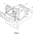
- FIG. 1 and FIG. 2 is a perspective schematic view of the power supply device with an illuminated handle in this disclosure and a partial perspective exploded schematic view of another side of the power supply device with an illuminated handle in this disclosure.
- This disclosure is a power supply device 1 with an illuminated handle 41 including a device body 10, a fan assembly 20 and a light source set 42.
- the device body 10 includes a case 11 and a control board 12, and the control board 12 is disposed in the case 11.
- the fan assembly 20 is disposed in the case 11.
- the light source set 42 is disposed on one side of the fan assembly 20.
- the light source set 42 includes a flexible printed circuit board 421 and a wire 43.
- the wire 43 is electrically connected to the flexible printed circuit board 421 and connected to the control board 12.
- control board 12 serves as the system controller within the power supply device 1. That is, the control board 12 controls the central controller or specific circuits of the entire server system. Through the light source set 42 being electrically connected to the control board 12, the system controller or specific circuits within the power supply device 1 may control the operation of the light source set 42.
- the power supply device 1 further includes an adapter board 30 disposed on one side of the light source set 42.
- the arrangement of the adapter board 30 is described below.
- the adapter board 30 includes a light conduction portion 32 and a wire connection portion 33.
- the wire 43 is electrically connected to the wire connection portion 33 and further connected to the control board 12.
- the flexible printed circuit board 421 is electrically connected to the light conduction portion 32.
- FIG. 3 to FIG. 5 are a perspective schematic view of the separation of the power socket set from the power supply device in this disclosure, a perspective schematic view of the power socket set in this disclosure, and a perspective exploded schematic view of the illuminated handle in this disclosure.
- the light conduction portion 32 of the adapter board 30 includes a flexible printed cable (FPC) connector.
- the wire connection portion 33 includes a wire connector or a golden finger connection pad.
- the wire connection portion 33 may include a surface-mounted electronic component or a plug-in electronic component according to requirements of use.
- the wire connection portion 33 includes a dip connector.
- the power supply device 1 further includes a handle 41 combined with the fan assembly 20. Additionally, at least a part of the flexible printed circuit board 421 is arranged on the end surface of the handle 41 facing the fan assembly 20.
- the handle 41 is combined on an outer surface of the fan assembly 20 away from the case 11, and the handle 41 may be made of transparent plastic. The light emitted from the light source set 42 may penetrate into the handle 41 to make the handle 41 form a luminous handle. Therefore, users may identify the position of the handle 41 under the environments with insufficient lighting to facilitate user exerting a force on the handle 41 to extract the power supply device 1.
- the power supply device 1 further includes a power socket set 13 combined on one side of the fan assembly 20.
- the power socket set 13 includes a socket body 131, and the socket body 131 includes a socket bracket 132.
- the socket bracket 132 may made of metal and includes a pin 133 being bended and extended.
- the adapter board 30 is arranged on the socket body 131. Specifically, the adapter board 30 is disposed on the socket bracket 132 of the socket body 131. In more detail, a slot 310 is disposed on the circuit board 31 of the adapter board 30. The adapter board 30 is positioned on the socket body 131 through the pin 133 being inserted in the slot 310. The adapter board 30 is positioned on the socket body 131 through the pin 133 being inserted in the slot 310.
- the handle 41 is a U-shaped handle, and the two ends of the handle 41 are fixed on one side of the fan assembly 20 adjacent to the power socket set 13.
- the socket bracket 132 is formed with a limiting slot 130 at the location of the pin 133. Furthermore, the adapter board 30 is placed within the limiting slot 130. Accordingly, the outer edge of the adapter board 30 is restricted by the limiting slot 130 and may not be moved.
- the socket bracket 132 is mainly used to fix the socket body 131 in the case 11.
- the socket body 131 may be more stable when the power cord being plugged or unplugged.
- the handle 41 includes a protrusion 411 disposed on the end surface of the handle 41 facing the fan assembly 20. Additionally, a positioning hole 420 is disposed on the flexible printed circuit board 421 correspondingly. The flexible printed circuit board 421 is positioned on the end surface of the handle 41 through the protrusion 411 being inserted in the positioning hole 420.
- the light source set 42 includes at least one light source 422 disposed on the flexible printed circuit board 421.
- the light source 422 includes, but not limited, an LED.
- the flexible printed circuit board 421 includes at least one conducting section 4211 and a connecting section 4212 connecting to the conducting section 4211.
- the conducting section 4211 is combined with a light source 422 and positioned on the end surface of the handle 41.
- the connecting section 4212 is connected to the light conduction portion 32 of the adapter board 30.
- the light source 422 is connected to the adapter board 30 through the flexible printed circuit board 421 and the light conduction portion 32, and is further connected to a wire 43 through the adapter board 30 and the wire connection portion 33 and then is connected to the control board 12 located at the rear side through the wire 43.
- the control board 12 may control the light source 422.
- the power supply device 1 further includes a plurality of fasteners 50.
- the fan assembly 20 includes a plurality of through holes 21 for insertions of the fasteners 50.
- a perforation 4210 is disposed on the flexible printed circuit board 421, and two screw holes 410 are disposed on two end surface of the handle 41 separately.
- Each fastener 50 passes through the through hole 21, the perforation 4210 and the screw hole 410 sequentially to fix the handle 41.
- FIG. 6 is another embodiment of the adapter board in this disclosure.
- the adapter board 30 includes a circuit board 31, a light conduction portion 32 electrically connected to the circuit board 31, and a wire connection portion 33'.
- the difference of this embodiment is that the arrangement of the wire connection portion 33'.
- the wire connection portion 33' is a surface mount electronic component.
Landscapes
- Engineering & Computer Science (AREA)
- Microelectronics & Electronic Packaging (AREA)
- General Engineering & Computer Science (AREA)
- Theoretical Computer Science (AREA)
- Physics & Mathematics (AREA)
- Power Engineering (AREA)
- General Physics & Mathematics (AREA)
- Thermal Sciences (AREA)
- Human Computer Interaction (AREA)
- Computer Hardware Design (AREA)
- Arrangement Of Elements, Cooling, Sealing, Or The Like Of Lighting Devices (AREA)
Abstract
Description
- The technical field relates to a power supply device, and more particularly, to a power supply device with an illuminated handle.
- The Open Compute Project (OCP) organization provides the requirement for the Modular Hardware System-Common Redundant Power Supply (M-CRPS) with the usage of illuminated handles. The configuration involves disposing flexible circuit board on the rear side of the handle and connecting it to the rear control board for controlling and providing the power required for the operation of the illuminated handle.
- However, the cost of flexible circuit board is higher, and when the flexible circuit board is connected to the rear control board, the flexible circuit board passes through the primary and secondary sides of transformers in the circuit, thereby the flexible circuit board requiring additional insulation components, such as double-layer high-temperature adhesive tape, to meet safety regulations. That results in further increased overall costs.
- In view of the above drawbacks, the inventor proposes this disclosure based on his expert knowledge and elaborate researches in order to solve the problems of related art.
- This disclosure is a power supply device with an illuminated handle, which the fan assembly is combined with the light source set and the handle, and users may exert a force on the handle under environments with insufficient light to extract the power supply device.
- This disclosure is a power supply device with an illuminated handle including a device body, a fan assembly, a light source set, and a handle. The device body includes a case and a control board. The control board is disposed in the case. The fan assembly is disposed in the case. The light source set is disposed on a side of the fan assembly and includes a flexible printed circuit board and a wire. The wire is electrically connected to the flexible printed circuit board and connected to the control board. The handle is combined with the fan assembly, wherein at least a part of the flexible printed circuit board is disposed on an end surface of the handle facing the fan assembly.
- In comparison with the related art, the power supply device with an illuminated handle of this disclosure is to combine the light source set and the handle with the fan assembly. The light source set includes a flexible printed circuit board and a wire. The wire is electrically connected to the flexible printed circuit board and connected to the control board located on the rear side of the case. As a result, the length of the flexible printed circuit board is shortened, and the objective of reducing costs and complying with safety regulations are achieved.
- The features of the disclosure believed to be novel are set forth with particularity in the appended claims. The disclosure itself, however, may be best understood by reference to the following detailed description of the disclosure, which describes a number of exemplary embodiments of the disclosure, taken in conjunction with the accompanying drawings, in which:
-
FIG. 1 is a perspective schematic view of the power supply device with an illuminated handle in this disclosure. -
FIG. 2 is a partial perspective exploded schematic view of another side of the power supply device with an illuminated handle in this disclosure. -
FIG. 3 is a perspective schematic view of the separation of the power socket set from the power supply device in this disclosure. -
FIG. 4 is a perspective schematic view of the power socket set in this disclosure. -
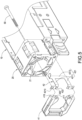
FIG. 5 is a perspective exploded schematic view of the illuminated handle in this disclosure. -
FIG. 6 is another embodiment of the adapter board in this disclosure. - The technical contents of this disclosure will become apparent with the detailed description of embodiments accompanied with the illustration of related drawings as follows. It is intended that the embodiments and drawings disclosed herein are to be considered illustrative rather than restrictive.
- Please refer to
FIG. 1 andFIG. 2 , which is a perspective schematic view of the power supply device with an illuminated handle in this disclosure and a partial perspective exploded schematic view of another side of the power supply device with an illuminated handle in this disclosure. This disclosure is apower supply device 1 with anilluminated handle 41 including adevice body 10, afan assembly 20 and alight source set 42. Thedevice body 10 includes acase 11 and acontrol board 12, and thecontrol board 12 is disposed in thecase 11. Thefan assembly 20 is disposed in thecase 11. Furthermore, thelight source set 42 is disposed on one side of thefan assembly 20. Thelight source set 42 includes a flexible printedcircuit board 421 and awire 43. Thewire 43 is electrically connected to the flexible printedcircuit board 421 and connected to thecontrol board 12. - It is worth noticing the
control board 12 serves as the system controller within thepower supply device 1. That is, thecontrol board 12 controls the central controller or specific circuits of the entire server system. Through thelight source set 42 being electrically connected to thecontrol board 12, the system controller or specific circuits within thepower supply device 1 may control the operation of thelight source set 42. - In this embodiment, the
power supply device 1 further includes anadapter board 30 disposed on one side of thelight source set 42. The arrangement of theadapter board 30 is described below. - Specifically, the
adapter board 30 includes alight conduction portion 32 and awire connection portion 33. Thewire 43 is electrically connected to thewire connection portion 33 and further connected to thecontrol board 12. Moreover, the flexible printedcircuit board 421 is electrically connected to thelight conduction portion 32. - Please refer to
FIG. 3 to FIG. 5 , which are a perspective schematic view of the separation of the power socket set from the power supply device in this disclosure, a perspective schematic view of the power socket set in this disclosure, and a perspective exploded schematic view of the illuminated handle in this disclosure. In this embodiment, thelight conduction portion 32 of theadapter board 30 includes a flexible printed cable (FPC) connector. Additionally, thewire connection portion 33 includes a wire connector or a golden finger connection pad. - It should be noted that the arrangement of the
light conduction portion 32 and thewire connection portion 33 only needs to achieve the purpose of electrical connection and is not limited to the above embodiments. Moreover, thewire connection portion 33 may include a surface-mounted electronic component or a plug-in electronic component according to requirements of use. In the embodiment of this disclosure, thewire connection portion 33 includes a dip connector. - Moreover, the
power supply device 1 further includes ahandle 41 combined with thefan assembly 20. Additionally, at least a part of the flexible printedcircuit board 421 is arranged on the end surface of thehandle 41 facing thefan assembly 20. In this embodiment, thehandle 41 is combined on an outer surface of thefan assembly 20 away from thecase 11, and thehandle 41 may be made of transparent plastic. The light emitted from thelight source set 42 may penetrate into thehandle 41 to make thehandle 41 form a luminous handle. Therefore, users may identify the position of thehandle 41 under the environments with insufficient lighting to facilitate user exerting a force on thehandle 41 to extract thepower supply device 1. - In one embodiment of this disclosure, the
power supply device 1 further includes a power socket set 13 combined on one side of thefan assembly 20. The power socket set 13 includes asocket body 131, and thesocket body 131 includes asocket bracket 132. Thesocket bracket 132 may made of metal and includes apin 133 being bended and extended. - In this embodiment, the
adapter board 30 is arranged on thesocket body 131. Specifically, theadapter board 30 is disposed on thesocket bracket 132 of thesocket body 131. In more detail, aslot 310 is disposed on thecircuit board 31 of theadapter board 30. Theadapter board 30 is positioned on thesocket body 131 through thepin 133 being inserted in theslot 310. Theadapter board 30 is positioned on thesocket body 131 through thepin 133 being inserted in theslot 310. - In one embodiment of this disclosure, the
handle 41 is a U-shaped handle, and the two ends of thehandle 41 are fixed on one side of thefan assembly 20 adjacent to thepower socket set 13. - It is worth noticing that the
socket bracket 132 is formed with a limitingslot 130 at the location of thepin 133. Furthermore, theadapter board 30 is placed within the limitingslot 130. Accordingly, the outer edge of theadapter board 30 is restricted by the limitingslot 130 and may not be moved. - It should be noted that the
socket bracket 132 is mainly used to fix thesocket body 131 in thecase 11. Thus, thesocket body 131 may be more stable when the power cord being plugged or unplugged. - In this embodiment, the
handle 41 includes aprotrusion 411 disposed on the end surface of thehandle 41 facing thefan assembly 20. Additionally, apositioning hole 420 is disposed on the flexible printedcircuit board 421 correspondingly. The flexible printedcircuit board 421 is positioned on the end surface of thehandle 41 through theprotrusion 411 being inserted in thepositioning hole 420. - In more detail, the light source set 42 includes at least one
light source 422 disposed on the flexible printedcircuit board 421. In some embodiments, thelight source 422 includes, but not limited, an LED. Moreover, the flexible printedcircuit board 421 includes at least oneconducting section 4211 and a connectingsection 4212 connecting to theconducting section 4211. Theconducting section 4211 is combined with alight source 422 and positioned on the end surface of thehandle 41. The connectingsection 4212 is connected to thelight conduction portion 32 of theadapter board 30. - Accordingly, the
light source 422 is connected to theadapter board 30 through the flexible printedcircuit board 421 and thelight conduction portion 32, and is further connected to awire 43 through theadapter board 30 and thewire connection portion 33 and then is connected to thecontrol board 12 located at the rear side through thewire 43. As a result, thecontrol board 12 may control thelight source 422. - As shown in
FIG. 5 , thepower supply device 1 further includes a plurality offasteners 50. Moreover, thefan assembly 20 includes a plurality of throughholes 21 for insertions of thefasteners 50. Aperforation 4210 is disposed on the flexible printedcircuit board 421, and twoscrew holes 410 are disposed on two end surface of thehandle 41 separately. Eachfastener 50 passes through the throughhole 21, theperforation 4210 and thescrew hole 410 sequentially to fix thehandle 41. - Please refer to
FIG. 6 , which is another embodiment of the adapter board in this disclosure. This embodiment is similar to the previous embodiment. Theadapter board 30 includes acircuit board 31, alight conduction portion 32 electrically connected to thecircuit board 31, and a wire connection portion 33'. The difference of this embodiment is that the arrangement of the wire connection portion 33'. In this embodiment, the wire connection portion 33' is a surface mount electronic component.
Claims (10)
- A power supply device (1) with an illuminated handle, comprising:a device body (10), comprising a case (11) and a control board (12) disposed in the case (11);a fan assembly (20), disposed in the case (11), characterized in thata light source set (42), disposed on an end surface of the fan assembly (20), comprising a flexible printed circuit board (421) and a wire (43), the wire (43) electrically connected to the flexible printed circuit board (421) and connected to the control board (12); anda handle, combined with the fan assembly, wherein at least a part of the flexible printed circuit board is disposed on an end surface of the handle facing the fan assembly.
- The power supply device (1) with an illuminated handle according to claim 1, further comprising an adapter board (30) arranged on a side of the light source set (42).
- The power supply device (1) with an illuminated handle according to claim 2, further comprising a power socket set (13) combined on a side of the fan assembly (20), wherein the power socket set (13) comprises a socket body (131), and the adapter board (30) is arranged on the socket body (131).
- The power supply device (1) with an illuminated handle according to claim 3, wherein the socket body (131) comprises a socket bracket (132), and the adapter board (30) is disposed on the socket bracket (132).
- The power supply device (1) with an illuminated handle according to claim 4, wherein the socket bracket (132) comprises a pin (133) extended curvedly, a slot (310) is defined on the adapter board (30), and the adapter board (30) is positioned on the socket body (131) through the pin (133) being inserted in the slot (310).
- The power supply device (1) with an illuminated handle according to claim 2, wherein the adapter board (30) comprises a wire connection portion (33, 33'), and the wire (43) is electrically connected to the wire connection portion (33, 33').
- The power supply device (1) with an illuminated handle according to claim 2, wherein the adapter board (30) comprises a light conduction portion (32), and the flexible printed circuit board (421) is electrically connected to the light conduction portion (32).
- The power supply device (1) with an illuminated handle according to claim 1, wherein the handle (41) comprises a protrusion (411) disposed on the end surface thereof facing the fan assembly (20), a positioning hole (420) is correspondingly defined on the flexible printed circuit board (421), and the flexible printed circuit board (421) is positioned on the end surface of the handle (41) through the protrusion (411) being inserted in the positioning hole (420).
- The power supply device (1) with an illuminated handle according to claim 8, wherein the light source set (42) comprises at least one light source (422) disposed on the flexible printed circuit board (421), the flexible printed circuit board (421) comprises at least one conducting section (4211) and a connecting section (4212) connected to the at least one conducting section (4211), and the at least one conducting section (4211) is combined with the at least one light source (422) and positioned on the end surface of the handle (41).
- The power supply device (1) with an illuminated handle according to claim 1, further comprising a plurality of fasteners (50), wherein the fan assembly (20) comprises a plurality of through holes (21) inserted by the plurality of fasteners (50), a perforation (4210) is defined on the flexible printed circuit board (421) and two screw holes (410) are respectively defined on two end surface of the handle (41), the handle (41) is fixed through each fastener (50) passing through each through hole (21), the perforation (4210) and one of the screw holes (410) sequentially.
Applications Claiming Priority (1)
| Application Number | Priority Date | Filing Date | Title |
|---|---|---|---|
| CN202310664079.7A CN119088189A (en) | 2023-06-06 | 2023-06-06 | Power supply device with luminous handle |
Publications (3)
| Publication Number | Publication Date |
|---|---|
| EP4475641A1 true EP4475641A1 (en) | 2024-12-11 |
| EP4475641B1 EP4475641B1 (en) | 2025-08-06 |
| EP4475641C0 EP4475641C0 (en) | 2025-08-06 |
Family
ID=88297252
Family Applications (1)
| Application Number | Title | Priority Date | Filing Date |
|---|---|---|---|
| EP23202177.4A Active EP4475641B1 (en) | 2023-06-06 | 2023-10-06 | Power supply device with illuminated handle |
Country Status (3)
| Country | Link |
|---|---|
| US (1) | US12396113B2 (en) |
| EP (1) | EP4475641B1 (en) |
| CN (1) | CN119088189A (en) |
Families Citing this family (1)
| Publication number | Priority date | Publication date | Assignee | Title |
|---|---|---|---|---|
| TWI900335B (en) * | 2023-11-14 | 2025-10-01 | 台達電子工業股份有限公司 | Fool-proof structure for shelf and plug-in unit |
Citations (2)
| Publication number | Priority date | Publication date | Assignee | Title |
|---|---|---|---|---|
| US20120194350A1 (en) * | 2011-01-28 | 2012-08-02 | Crisp Richard A | Equipment module indicator handle and methods for indicating equipment module status |
| US20180070473A1 (en) * | 2016-09-07 | 2018-03-08 | Dell Products L.P. | Modular fan chassis air filtering system |
Family Cites Families (7)
| Publication number | Priority date | Publication date | Assignee | Title |
|---|---|---|---|---|
| CN202603074U (en) | 2012-05-22 | 2012-12-12 | 台达电子工业股份有限公司 | Power supply device and modularized power supply thereof |
| TWI606467B (en) | 2015-07-01 | 2017-11-21 | 貝爾威勒電子股份有限公司 | Assembly of cable and connector |
| CN205544954U (en) | 2016-01-14 | 2016-08-31 | 康舒科技股份有限公司 | Power supply handle with indicator light |
| CN106771980A (en) | 2017-01-16 | 2017-05-31 | 京东方科技集团股份有限公司 | A kind of flexible circuit board detecting device and detection method |
| TWM577968U (en) * | 2019-01-19 | 2019-05-11 | 擎宏電子企業有限公司 | Adapter board structure for power module of DC power supply |
| CN212515613U (en) | 2020-07-28 | 2021-02-09 | 苏州浪潮智能科技有限公司 | Fan module |
| CN216133607U (en) | 2021-07-30 | 2022-03-25 | 东莞帝光智能显示有限公司 | A colorful display backlight structure |
-
2023
- 2023-06-06 CN CN202310664079.7A patent/CN119088189A/en active Pending
- 2023-09-27 US US18/373,282 patent/US12396113B2/en active Active
- 2023-10-06 EP EP23202177.4A patent/EP4475641B1/en active Active
Patent Citations (2)
| Publication number | Priority date | Publication date | Assignee | Title |
|---|---|---|---|---|
| US20120194350A1 (en) * | 2011-01-28 | 2012-08-02 | Crisp Richard A | Equipment module indicator handle and methods for indicating equipment module status |
| US20180070473A1 (en) * | 2016-09-07 | 2018-03-08 | Dell Products L.P. | Modular fan chassis air filtering system |
Also Published As
| Publication number | Publication date |
|---|---|
| EP4475641B1 (en) | 2025-08-06 |
| US12396113B2 (en) | 2025-08-19 |
| EP4475641C0 (en) | 2025-08-06 |
| CN119088189A (en) | 2024-12-06 |
| US20240414863A1 (en) | 2024-12-12 |
Similar Documents
| Publication | Publication Date | Title |
|---|---|---|
| EP1949498B1 (en) | Flexible high-power led lighting system | |
| EP1735872B1 (en) | Flexible high-power led lighting system | |
| US20120170292A1 (en) | Illuminated receptacle | |
| EP4475641B1 (en) | Power supply device with illuminated handle | |
| CN103999293B (en) | Electrical connectors for use with printed circuit boards | |
| EP4474700A1 (en) | Power supply device | |
| US12305655B2 (en) | Parallel-connected lighting fan | |
| US9748723B2 (en) | Solder-less board-to-wire connector | |
| EP4474698A1 (en) | Power supply device combined with vibration-resistant fan assembly having illuminated handle | |
| US11437208B2 (en) | Electrical switch with identification features | |
| EP4628787A1 (en) | Track light | |
| CN105551868B (en) | Structure and processing technology for freely inserting and pulling electronic component on circuit board | |
| CN111536449B (en) | Track Light Assemblies | |
| JP2010021123A (en) | Thin flexible lighting device | |
| TWI868724B (en) | Power supply | |
| CN206694940U (en) | LED heat plugs indicator lamp and electrical equipment | |
| CN210398597U (en) | Modularized LED track lighting device | |
| CN106971887A (en) | Button switch and button switch unit | |
| CN102447184A (en) | Connector and illuminating device | |
| CN205544954U (en) | Power supply handle with indicator light | |
| JP2003069167A (en) | Substrate for light emitting diode lighting equipment | |
| EP4667750A1 (en) | Parallel-connected lighting fan | |
| EP4033144A1 (en) | Driver for driving a light engine of a luminaire | |
| CN113963876B (en) | Sliding variable resistance device with luminous function | |
| CN221900315U (en) | Multifunctional integrated board with universal integrated power supply |
Legal Events
| Date | Code | Title | Description |
|---|---|---|---|
| PUAI | Public reference made under article 153(3) epc to a published international application that has entered the european phase |
Free format text: ORIGINAL CODE: 0009012 |
|
| STAA | Information on the status of an ep patent application or granted ep patent |
Free format text: STATUS: REQUEST FOR EXAMINATION WAS MADE |
|
| 17P | Request for examination filed |
Effective date: 20240630 |
|
| AK | Designated contracting states |
Kind code of ref document: A1 Designated state(s): AL AT BE BG CH CY CZ DE DK EE ES FI FR GB GR HR HU IE IS IT LI LT LU LV MC ME MK MT NL NO PL PT RO RS SE SI SK SM TR |
|
| GRAP | Despatch of communication of intention to grant a patent |
Free format text: ORIGINAL CODE: EPIDOSNIGR1 |
|
| STAA | Information on the status of an ep patent application or granted ep patent |
Free format text: STATUS: GRANT OF PATENT IS INTENDED |
|
| INTG | Intention to grant announced |
Effective date: 20250326 |
|
| GRAS | Grant fee paid |
Free format text: ORIGINAL CODE: EPIDOSNIGR3 |
|
| GRAA | (expected) grant |
Free format text: ORIGINAL CODE: 0009210 |
|
| STAA | Information on the status of an ep patent application or granted ep patent |
Free format text: STATUS: THE PATENT HAS BEEN GRANTED |
|
| AK | Designated contracting states |
Kind code of ref document: B1 Designated state(s): AL AT BE BG CH CY CZ DE DK EE ES FI FR GB GR HR HU IE IS IT LI LT LU LV MC ME MK MT NL NO PL PT RO RS SE SI SK SM TR |
|
| REG | Reference to a national code |
Ref country code: GB Ref legal event code: FG4D |
|
| REG | Reference to a national code |
Ref country code: CH Ref legal event code: EP |
|
| REG | Reference to a national code |
Ref country code: IE Ref legal event code: FG4D |
|
| REG | Reference to a national code |
Ref country code: DE Ref legal event code: R096 Ref document number: 602023005432 Country of ref document: DE |
|
| U01 | Request for unitary effect filed |
Effective date: 20250813 |
|
| U07 | Unitary effect registered |
Designated state(s): AT BE BG DE DK EE FI FR IT LT LU LV MT NL PT RO SE SI Effective date: 20250821 |
|
| U20 | Renewal fee for the european patent with unitary effect paid |
Year of fee payment: 3 Effective date: 20250922 |
|
| PG25 | Lapsed in a contracting state [announced via postgrant information from national office to epo] |
Ref country code: IS Free format text: LAPSE BECAUSE OF FAILURE TO SUBMIT A TRANSLATION OF THE DESCRIPTION OR TO PAY THE FEE WITHIN THE PRESCRIBED TIME-LIMIT Effective date: 20251206 |
|
| PG25 | Lapsed in a contracting state [announced via postgrant information from national office to epo] |
Ref country code: NO Free format text: LAPSE BECAUSE OF FAILURE TO SUBMIT A TRANSLATION OF THE DESCRIPTION OR TO PAY THE FEE WITHIN THE PRESCRIBED TIME-LIMIT Effective date: 20251106 |
|
| PG25 | Lapsed in a contracting state [announced via postgrant information from national office to epo] |
Ref country code: HR Free format text: LAPSE BECAUSE OF FAILURE TO SUBMIT A TRANSLATION OF THE DESCRIPTION OR TO PAY THE FEE WITHIN THE PRESCRIBED TIME-LIMIT Effective date: 20250806 |
|
| PG25 | Lapsed in a contracting state [announced via postgrant information from national office to epo] |
Ref country code: GR Free format text: LAPSE BECAUSE OF FAILURE TO SUBMIT A TRANSLATION OF THE DESCRIPTION OR TO PAY THE FEE WITHIN THE PRESCRIBED TIME-LIMIT Effective date: 20251107 |
|
| PG25 | Lapsed in a contracting state [announced via postgrant information from national office to epo] |
Ref country code: PL Free format text: LAPSE BECAUSE OF FAILURE TO SUBMIT A TRANSLATION OF THE DESCRIPTION OR TO PAY THE FEE WITHIN THE PRESCRIBED TIME-LIMIT Effective date: 20250806 |
|
| PG25 | Lapsed in a contracting state [announced via postgrant information from national office to epo] |
Ref country code: RS Free format text: LAPSE BECAUSE OF FAILURE TO SUBMIT A TRANSLATION OF THE DESCRIPTION OR TO PAY THE FEE WITHIN THE PRESCRIBED TIME-LIMIT Effective date: 20251106 |
|
| PG25 | Lapsed in a contracting state [announced via postgrant information from national office to epo] |
Ref country code: ES Free format text: LAPSE BECAUSE OF FAILURE TO SUBMIT A TRANSLATION OF THE DESCRIPTION OR TO PAY THE FEE WITHIN THE PRESCRIBED TIME-LIMIT Effective date: 20250806 |
|
| PG25 | Lapsed in a contracting state [announced via postgrant information from national office to epo] |
Ref country code: SM Free format text: LAPSE BECAUSE OF FAILURE TO SUBMIT A TRANSLATION OF THE DESCRIPTION OR TO PAY THE FEE WITHIN THE PRESCRIBED TIME-LIMIT Effective date: 20250806 |
|
| PG25 | Lapsed in a contracting state [announced via postgrant information from national office to epo] |
Ref country code: CZ Free format text: LAPSE BECAUSE OF FAILURE TO SUBMIT A TRANSLATION OF THE DESCRIPTION OR TO PAY THE FEE WITHIN THE PRESCRIBED TIME-LIMIT Effective date: 20250806 |
|
| PG25 | Lapsed in a contracting state [announced via postgrant information from national office to epo] |
Ref country code: SK Free format text: LAPSE BECAUSE OF FAILURE TO SUBMIT A TRANSLATION OF THE DESCRIPTION OR TO PAY THE FEE WITHIN THE PRESCRIBED TIME-LIMIT Effective date: 20250806 |