EP4475523A1 - Vision camera for a driver monitoring system and method for assembling a vision camera - Google Patents
Vision camera for a driver monitoring system and method for assembling a vision camera Download PDFInfo
- Publication number
- EP4475523A1 EP4475523A1 EP23177152.8A EP23177152A EP4475523A1 EP 4475523 A1 EP4475523 A1 EP 4475523A1 EP 23177152 A EP23177152 A EP 23177152A EP 4475523 A1 EP4475523 A1 EP 4475523A1
- Authority
- EP
- European Patent Office
- Prior art keywords
- bridge
- printed circuit
- housing
- circuit board
- camera
- Prior art date
- Legal status (The legal status is an assumption and is not a legal conclusion. Google has not performed a legal analysis and makes no representation as to the accuracy of the status listed.)
- Granted
Links
Images





Classifications
-
- H—ELECTRICITY
- H04—ELECTRIC COMMUNICATION TECHNIQUE
- H04N—PICTORIAL COMMUNICATION, e.g. TELEVISION
- H04N23/00—Cameras or camera modules comprising electronic image sensors; Control thereof
- H04N23/50—Constructional details
- H04N23/55—Optical parts specially adapted for electronic image sensors; Mounting thereof
-
- B—PERFORMING OPERATIONS; TRANSPORTING
- B60—VEHICLES IN GENERAL
- B60R—VEHICLES, VEHICLE FITTINGS, OR VEHICLE PARTS, NOT OTHERWISE PROVIDED FOR
- B60R11/00—Arrangements for holding or mounting articles, not otherwise provided for
- B60R11/04—Mounting of cameras operative during drive; Arrangement of controls thereof relative to the vehicle
-
- G—PHYSICS
- G03—PHOTOGRAPHY; CINEMATOGRAPHY; ANALOGOUS TECHNIQUES USING WAVES OTHER THAN OPTICAL WAVES; ELECTROGRAPHY; HOLOGRAPHY
- G03B—APPARATUS OR ARRANGEMENTS FOR TAKING PHOTOGRAPHS OR FOR PROJECTING OR VIEWING THEM; APPARATUS OR ARRANGEMENTS EMPLOYING ANALOGOUS TECHNIQUES USING WAVES OTHER THAN OPTICAL WAVES; ACCESSORIES THEREFOR
- G03B15/00—Special procedures for taking photographs; Apparatus therefor
- G03B15/02—Illuminating scene
- G03B15/03—Combinations of cameras with lighting apparatus; Flash units
-
- G—PHYSICS
- G03—PHOTOGRAPHY; CINEMATOGRAPHY; ANALOGOUS TECHNIQUES USING WAVES OTHER THAN OPTICAL WAVES; ELECTROGRAPHY; HOLOGRAPHY
- G03B—APPARATUS OR ARRANGEMENTS FOR TAKING PHOTOGRAPHS OR FOR PROJECTING OR VIEWING THEM; APPARATUS OR ARRANGEMENTS EMPLOYING ANALOGOUS TECHNIQUES USING WAVES OTHER THAN OPTICAL WAVES; ACCESSORIES THEREFOR
- G03B17/00—Details of cameras or camera bodies; Accessories therefor
- G03B17/02—Bodies
-
- H—ELECTRICITY
- H04—ELECTRIC COMMUNICATION TECHNIQUE
- H04N—PICTORIAL COMMUNICATION, e.g. TELEVISION
- H04N23/00—Cameras or camera modules comprising electronic image sensors; Control thereof
- H04N23/50—Constructional details
-
- H—ELECTRICITY
- H04—ELECTRIC COMMUNICATION TECHNIQUE
- H04N—PICTORIAL COMMUNICATION, e.g. TELEVISION
- H04N23/00—Cameras or camera modules comprising electronic image sensors; Control thereof
- H04N23/50—Constructional details
- H04N23/51—Housings
-
- H—ELECTRICITY
- H04—ELECTRIC COMMUNICATION TECHNIQUE
- H04N—PICTORIAL COMMUNICATION, e.g. TELEVISION
- H04N23/00—Cameras or camera modules comprising electronic image sensors; Control thereof
- H04N23/50—Constructional details
- H04N23/52—Elements optimising image sensor operation, e.g. for electromagnetic interference [EMI] protection or temperature control by heat transfer or cooling elements
-
- H—ELECTRICITY
- H04—ELECTRIC COMMUNICATION TECHNIQUE
- H04N—PICTORIAL COMMUNICATION, e.g. TELEVISION
- H04N23/00—Cameras or camera modules comprising electronic image sensors; Control thereof
- H04N23/56—Cameras or camera modules comprising electronic image sensors; Control thereof provided with illuminating means
-
- H—ELECTRICITY
- H04—ELECTRIC COMMUNICATION TECHNIQUE
- H04N—PICTORIAL COMMUNICATION, e.g. TELEVISION
- H04N23/00—Cameras or camera modules comprising electronic image sensors; Control thereof
- H04N23/57—Mechanical or electrical details of cameras or camera modules specially adapted for being embedded in other devices
-
- H—ELECTRICITY
- H04—ELECTRIC COMMUNICATION TECHNIQUE
- H04N—PICTORIAL COMMUNICATION, e.g. TELEVISION
- H04N23/00—Cameras or camera modules comprising electronic image sensors; Control thereof
- H04N23/70—Circuitry for compensating brightness variation in the scene
- H04N23/74—Circuitry for compensating brightness variation in the scene by influencing the scene brightness using illuminating means
-
- H—ELECTRICITY
- H04—ELECTRIC COMMUNICATION TECHNIQUE
- H04N—PICTORIAL COMMUNICATION, e.g. TELEVISION
- H04N25/00—Circuitry of solid-state image sensors [SSIS]; Control thereof
- H04N25/20—Circuitry of solid-state image sensors [SSIS]; Control thereof for transforming only infrared radiation into image signals
- H04N25/21—Circuitry of solid-state image sensors [SSIS]; Control thereof for transforming only infrared radiation into image signals for transforming thermal infrared radiation into image signals
-
- H—ELECTRICITY
- H04—ELECTRIC COMMUNICATION TECHNIQUE
- H04N—PICTORIAL COMMUNICATION, e.g. TELEVISION
- H04N5/00—Details of television systems
- H04N5/30—Transforming light or analogous information into electric information
- H04N5/33—Transforming infrared radiation
Definitions
- the invention relates to a vision camera for a driver monitoring system.
- the vision camera comprises a housing and a cover.
- the housing carries a lens and a printed circuit board with IR diodes on either side of the lens.
- a printed circuit board for the camera is positioned in the housing.
- the invention relates to a method for assembling a vision camera for a driver monitoring system.
- the printed circuit boards are populated with connectors needed to power the IR diodes on the two printed circuit boards. Complicated assembly steps are needed to ensure the assembly of all these components and the electrical connections required for operation of the driver monitoring system. Automatic assembly of the vision camera is difficult to be implemented due to the wire connections between the different printed circuit boards of the housing for the vision camera.
- a further object of the present invention is to provide a method for assembling a vision camera for a driver monitoring system, which allows an automatization of the assembly steps and reduces the total number of parts.
- the vision camera for a driver monitoring system according to the invention, comprises a housing and a cover.
- the housing carrying a lens, a printed circuit board with IR diodes on either side of the lens, and a printed circuit board for the camera positioned in the housing.
- An embodiment of the vision camera according to the invention comprises a bridge having an opening for the lens and an illumination opening.
- the illumination openings e.g., two
- a plurality of electrical connectors are integral parts of the bridge. The electrical connectors electrically contact the printed circuit board with IR diodes and the printed circuit board for the camera once the bridge is mounted to the housing of the vision camera.
- This construction has the advantage of allowing automatic assembly of the vision camera and simplifying the overall architecture of the driver monitoring system is. During the assembly of the vision camera, it is ensured that all required electrical connections are established. Furthermore, a certain degree of mechanical protection for the 2-IR diodes is achieved.
- an ISP printed circuit board is electrically connected to the printed circuit board for the camera.
- each of the plurality of electrical connectors of the bridge is in the form of a hook.
- a single electrical connector has a first contacting pin at a first free end and a second contacting pin at a second free end.
- the bridge is made by an injection molding process, and an injection molded plastic material of the bridge incorporates a plurality of at least partially embedded and overmolded electrical connectors.
- the overmolded electrical connectors are provided at a first end and a second end of the bridge.
- the first contacting pins of the electrical connectors, embedded in the bridge electrically contact the printed circuit board with the IR diodes.
- the second contacting pins of the electrical connectors, embedded in the bridge electrically contact the printed circuit board for the camera.
- an assembly surface for the lens is provided.
- Two cooling geometries are located laterally the assembly surface for the lens.
- At least one mounting feature for the bridge is located at or close to each cooling geometry.
- the bridge has formed a plurality of individual and separated legs at a first end and a second end. At least two legs carry embedded and overmolded electrical connectors, or at least two of the embedded and overmolded electrical connectors are part of the individual legs.
- Each cooling geometry of the housing has formed a plurality of fins thereon. Between each of two successive fins, an individual mounting opening is formed. The mounting openings are arranged to receive the individual legs of the bridge. Each of the individual legs may have a section with a grip and press geometry that cooperates with the mounting opening.
- the bridge which is configured to add two printed circuit boards with IR diodes, may have various embodiments with respect to the number of legs with electrical connectors.
- the individual legs with the electrical connectors may carry injection moulded plastic press-fits (assembly features), which can cooperate with mounting openings of the housing.
- the bridge carries a one-piece leg at a first end and at a second end of the bridge.
- the one-piece leg In the one-piece leg, at least two electrical connectors are embedded and overmolded an form an integral part of the one-piece leg.
- the cooling geometry on the housing has formed a plurality of fins and an elongated mounting opening.
- the two mounting openings are arranged to receive one of the two one-piece legs of the bridge.
- Each one-piece leg may have a section with an assembly feature that cooperates with the mounting opening so that the bridge is securely mounted to the housing.
- the bridge may be manufactured using a plastic injection molding process.
- the electrical connectors are initially placed in the mold at locations where the electrical connectors should be present due the various types of the bridge.
- a bridge may be used to ensure the electrical connection between the printed circuit board with IR diodes and printed circuit board for the camera.
- At least two electrical connectors are part of each leg of the bridge. The position and number of the electrical connectors in the legs may vary, so that different configurations of the bridge are possible.
- Another advantage of the present invention is that the architecture of the vision camera allows modularity of the parts that make up the vision camera. Furthermore, the different versions of the bridges (number of electrical connectors embedded in the bridges) lead to a variation in the position and number of legs that allow the press-fits for mounting the bridges to the housing.
- the bridge with the embedded connectors provides an electrical connection between the printed circuit boards for the IR diodes and the printed circuit board for the camera using the press-fit pins.
- the bridge results in a subassembly with three printed circuit board which are electrically connected.
- a printed circuit board for the camera is inserted into the housing, thus electrically connecting the printed circuit board to the bridge.
- the printed circuit board for the camera is pressed against the legs of the bridge, causing second contacting pins to establish the electrical contact and securing the printed circuit board for the camera in the housing.
- Figure 4 shows the assembled vision camera 10 according to the embodiment shown in Fig. 3 .
- bridge 20 that cooperates with housing 13 to provide a functional embodiment of vison camera 10.
- a plurality of electrical connectors 23 are an integral part of bridge 20.
- the electrical connectors 23 provide electric power to the printed circuit boards 11 for the IR diodes 12 located behind respective illumination openings 22 of bridge 20.
- the electrical connectors 23 supply electric power to camera printed circuit board 16 (see Fig. 3 ), which is in housing 13.
- Lens 4 is located behind an opening 21 of bridge 20.
- Figure 5 shows an exploded view of the vision camera 10 according to a further embodiment.
- the embodiment shown here differs from the embodiment in Fig. 3 in that a further embodiment of the bridge 20 is used to assemble vision camera 10. All other features are known from the exploded view of Fig. 3 .
- Figure 6 shows the assembled vision camera 10 according to the exploded view of the embodiment shown in Fig. 5 .
- Openings 22 are formed in bridge 20 for the printed circuit boards 11 for the IR diodes 12.
- the printed circuit boards 11 are located behind the respective illumination openings 22 of bridge 20.
- Lens 4 is located behind an opening 21 of bridge 20.
- FIG. 7A and 7B show two different perspective views of a bridge 20 according to one embodiment used for assembling a vision camera 10 as shown in Fig. 4 .
- the electrical connectors 23 are partially embedded and overmolded with the material, forming the bridge 20, which is manufactured by injection molding a plastic material.
- the electrical connectors 23 are an integral part of bridge 20.
- the embedded and overmolded electrical connectors 23 form individual legs 28, each of which having a section 29 with a grip and press geometry that provide an assembly feature to housing 13.
- the electrical connectors 23 are arranged at a first end 41 and at a second end 42 of bridge 20.
- Each electrical connector 23 has a first contacting pin 24 formed at a first free end 25 and a second contacting pin 26 formed at a second free end 27.
- the first contacting pins 24 reach into the illumination openings 22 arranged on either side of opening 21 for lens 4.
- Figure 8A to 8C show the installation process of the printed circuit boards 11 for IR diodes 12 to the bridge 20, as shown in Figs. 7A and 7B .
- a pair of locating pins 39 are formed near each illumination opening 22.
- the locating pins 39 are made of the same plastic material as the injection molded part of the bridge 20.
- Each printed circuit board 11 for IR diodes 12 is placed in relation to the illumination openings 22 of bridge 20, and at least the pair of locating pins 39 provide a press fit for the printed circuit boards 11 for IR diodes 12 and hold the printed circuit boards 11 for IR diodes 12 in place.
- Fig. 10D shows that the individual legs 28 carry an overmolded section 29.
- Section 29, if an electrical connector 23 is present, is formed around electrical connector 23 and is a grip with a press geometry.
- Leg 28 has section 29 formed even if an electrical connector 23 is not present at a specific position.
- Section 29 having an assembly feature 46 in the form of the grip with the press geometry is necessary for assembling bridge 20 to housing 13.
- the printed circuit boards 11 with the IR diodes 12 are mounted to bridge 20 at a location of the illumination openings 22 of bridge 20 (see Fig. 10E ).
- the locating pin 39 (see Fig. 8A , the pair of locating pins 39) assist in aligning and assembling printed circuit board 11 with IR diodes 12 to the illumination openings 22 of bridge 20.
- Figure 11A and 11B show various embodiments of the printed circuit boards 11 for IR diodes 12.
- the printed circuit boards 11 need to be adapted by means of appropriate holes or recesses 45 for press fits, and the position and number of pins may be customized according to requirements.
- the printed circuit boards 11 for IR diodes 12 have recesses 45 formed which facilitate positioning of the printed circuit board 11 at the defined position of bridge 20.
- the first contacting pins 24 (see Fig. 8A ) reach through passages 47 formed in the printed circuit board 11. At least two passages 47 are formed in the printed circuit board 11. The number of passages 47 depends on the number of electrical connectors 23 that are part of bridge 20.
- FIG 12 is a perspective view of the housing 13 for the camera 10 of Fig. 4 with detailed views ( Figs. 12A to 12C ) of specific housing features.
- the housing 13 is suitable for aluminum die casting technology.
- An assembly surface 30 for lens 4 (not shown) is placed on a base 31 of housing 13 and between cooling geometries 32 of housing 13 and has a rounded shape (see Fig. 12A ).
- Each cooling geometry 32 has a plurality of fins 33 arranged in a fan shape and open to one side of each cooling geometry 32 (see also Fig. 12B ).
- An individual mounting opening 34 is formed between two fins 33 (see Fig. 12C ).
- the individual mounting openings 34 are arranged on each cooling geometry 32 such that they receive the individual legs 28 of the embodiment of bridge 20 as shown in Figs. 7A to 7B .
- the cooling geometries 32, the plurality of fins 33 and the mounting openings 34 geometries for cooling and thermal paste dispensing are formed.
- Figures 13A to 13F show the mounting sequence of a bridge 20 together with other components of the vision camera 10 as shown in Fig. 3 .
- the printed circuit boards 11 with IR diodes 12 are mounted to each illumination opening 22 (see Figs. 8A to 8C ) of a bridge 20.
- the printed circuit boards 11 with IR diodes 12 are electrically connected by the bridge 20.
- the circuit boards 11 are temporarily fixed to bridge 20 until the next step.
- bridge 20 is assembled to housing 13 together with the printed circuit boards 11. Section 29 (see Figs.
- Cover 14 is fixed to housing 13 together with four fasteners 18.
- the fasteners 18 are, for example, screws placed at each corner of cover 14.
- the final assembly step is to assemble lens 4 through opening 21 for lens 4 in bridge 20. After this final step, the assembly of vision camera 10 is complete.
- FIG 14A and 14B show two different perspective views of a bridge 20 according to another embodiment of a vision camera 10.
- bridge 20 is mounted to housing 13 of vision camera 10.
- Bridge 20 carries a one-piece leg 36 at the first end 41 and an opposite one-piece leg 36 at the second end 42.
- Bridge 20 is formed by an injection molding process, and the electrical connectors 23 (see Fig. 18A ) are completely embedded in the one-piece legs 36 of bridge 20 made of a plastic material.
- the injection molding process is such that the first contacting pins 24 and the second contacting pins 26 of the electrical connectors 23 are not covered by the plastic material of bridge 20.
- the contacting pins 24 reach out to an inside 49 of bridge 20.
- each one-piece leg 36 in the embodiment shown here, has four electrical connectors 23 being part of the one-piece leg 36.
- the embodiment shown in Figs. 14A and 14B also has an opening 21 for lens 4 and an illumination opening 22 on both sides of the opening 21 for lens 4.
- Figure 15 shows an embodiment of the printed circuit board 11 for IR diodes 12 in conjunction with bridge 20 of Figs. 14A and 14B .
- Printed circuit board 11 has formed four passages 47 which can receive the second contacting pins 26 once the printed circuit board 11 is positioned in bridge 20.
- Figure 16A and 16B show the installation process of printed circuit board 11 to the bridge 20 as shown in Figs. 14A and 14B .
- Printed circuit board 11 is lowered along an arrow 60 to the inside 49 toward the illumination opening 22 until printed circuit board 11 covers illumination opening 22 and is then correctly positioned by means of the locating pins 39 and the first contacting pins 24 reach through the passages 47 of printed circuit board 11.
- Figure 17A and 17C show various embodiments of the printed circuit boards 11 for the IR diodes 12. The embodiments differ by the number of passages 47 for the first contacting pins 24.
- the corresponding printed circuit board 11 has four passages 47, meaning that the one-piece leg 36 has integrated four electrical connectors 23 and, consequently, four first contacting pins 24 (see, for example, the embodiment of Figs. 16A and 16B ).
- the corresponding printed circuit board 11 has two passages 47, which means that the one-piece leg 36 has integrated two electrical connectors 23 and, consequently, two first contacting pins 24.
- the corresponding printed circuit board 11 has three passages 47, which means that the one-piece leg 36 has integrated two electrical connectors 23 and, consequently, three first contacting pins 24.
- the different embodiments of the printed circuit boards 11 depend on the particular application.
- FIGS 18A to 18D show bridge 20 of Fig. 14 with detailed views of various structural elements of bridge 20.
- Electrical connector 23, which is part of bridge 20, is shown in Fig. 18A .
- Electrical connector 23 is also in the form of a hook.
- electrical connector 23 is designed as a press-fit electrical connector having two bends initially placed in the mold (not shown).
- Each electrical connector 23 has a first contacting pin 24 at a first free end 25 and a second contacting pin 26 at a second free end 27.
- the electrical connectors 23 are placed in the mold for overmolding in a press-fit manner to form the bridge 20 with the one-piece legs 36.
- Fig. 18B shows a geometry 43, which is attached to each one-piece leg 36.
- Geometry 43 is used to mount bridge 20 with the attached printed circuit boards 11 (see Fig. 16B ) to housing 13.
- Each one-piece leg 36 has an assembly feature 45 in a section 29 that is used to mount bridge 20 to housing 13 (see Fig. 18C ).
- geometry 43 is a grip and press geometry as previously described, i.e., which cooperates with mounting opening 34 to mount bridge 20 to housing 13.
- Fig. 18D shows a section through the inside 49 of bridge 20. The locating pin 39 on the inside 49 is used to position printed circuit board 11 (see Fig. 16B ).
- FIG 19 is a perspective view of the housing 13 for camera 10 of Fig. 6 with detailed views ( Figs. 19A to 19C ) of specific housing features.
- housing 13 is suitable for aluminum die casting technology.
- An assembly surface 30 for lens 4 (not shown), which has a rounded shape (see Fig. 19A ), is placed between cooling geometries 32 of housing 13.
- Each cooling geometry 32 has a plurality of parallel fins 33, which are open to one side of each cooling geometry 32.
- a mounting opening 34 (see Fig. 19C ) with an elongated shape is formed in housing 13.
- the mounting opening 34 of housing 13 cooperates with assembly feature 45 in section 29 of the one-piece leg 36 of bridge 20.
- the two mounting openings 34 each receive the one-piece leg 36 of bridge 20 to mount bridge 20 to housing 13.
- Figure 20A to 20F show the mounting sequence of bridge 20 together with other components of vision camera 10 as shown in Fig. 5 .
- the printed circuit boards 11 with IR diodes 12 are mounted to each illumination opening 22 of a bridge 20 (see Figs. 16A to 16b ).
- the printed circuit boards 11 with IR diodes 12 are electrically connected by bridge 20.
- the circuit boards 11 are temporarily fixed to bridge 20 until the next step.
- bridge 20 is inserted into the cooling geometries 32 of housing 13 together with the printed circuit boards 11.
- Section 29 (see Fig. 18C ) with assembly feature 45 of one-piece leg 36 is mounted to the housing 13 and holds bridge 20 in contact with housing 13.
- the contact (see Fig. 20C ) between the cooling geometries 32 of housing 13 and the printed circuit boards 11, which are located on bridge 20, is established by pressing the bridge 20 with printed circuit boards 11 against the cooling geometry 32.
- the printed circuit board 16 for the camera 10 is brought in electrical contact with the second contacting pins 26 (see Figs. 16A und 16B ) of bridge 20.
- the optical filter 15 is slid into the housing 13 and secured with a screw 8.
- the ISP printed circuit board 17 is placed in housing 13.
- Cover 14 is attached to housing 13 together with four fasteners 18.
- Fasteners 18 are, for example, screws placed at each corner of cover 14.
- the final assembly step is to assemble lens 4 through opening 21 for lens 4 in the bridge 20. After this final step, the assembly of vision camera 10 is completed.
Landscapes
- Engineering & Computer Science (AREA)
- Multimedia (AREA)
- Signal Processing (AREA)
- Physics & Mathematics (AREA)
- General Physics & Mathematics (AREA)
- Mechanical Engineering (AREA)
- Electromagnetism (AREA)
- Camera Bodies And Camera Details Or Accessories (AREA)
- Studio Devices (AREA)
Abstract
Description
- The invention relates to a vision camera for a driver monitoring system. The vision camera comprises a housing and a cover. The housing carries a lens and a printed circuit board with IR diodes on either side of the lens. A printed circuit board for the camera is positioned in the housing.
- Further, the invention relates to a method for assembling a vision camera for a driver monitoring system.
- The awareness of a driver of a vehicle is monitored by a Driver Monitoring System (DMS) based on a vision camera. According to the prior art, the vision camera is positioned inside the vehicle such that the driver is predictably in the center of the camera's field of view. Illumination is provided by an infrared light (IR) source, with the illumination positioned in the vicinity of the vision camera because the provided natural light is insufficient and the driver is not distracted by the IR illumination. The IR illumination is provided by IR diodes placed on two printed circuit boards (PCB) fixed with screws at a defined angle through a housing.
- In the current configuration (see
Fig. 2 ), the printed circuit boards are populated with connectors needed to power the IR diodes on the two printed circuit boards. Complicated assembly steps are needed to ensure the assembly of all these components and the electrical connections required for operation of the driver monitoring system. Automatic assembly of the vision camera is difficult to be implemented due to the wire connections between the different printed circuit boards of the housing for the vision camera. - It is an object of the present invention to provide a vision camera for a driver monitoring system which is easy to assemble and whose total number of parts is reduced.
- The above object is achieved by a vision camera for a driver monitoring system according to the features of
claim 1. - A further object of the present invention is to provide a method for assembling a vision camera for a driver monitoring system, which allows an automatization of the assembly steps and reduces the total number of parts.
- The above object is achieved by a method for assembling a vision camera for a driver monitoring system according to the features of
claim 12. - In an embodiment of the vision camera for a driver monitoring system according to the invention, the vision camera comprises a housing and a cover. The housing carrying a lens, a printed circuit board with IR diodes on either side of the lens, and a printed circuit board for the camera positioned in the housing.
- An embodiment of the vision camera according to the invention comprises a bridge having an opening for the lens and an illumination opening. The illumination openings (e.g., two) are arranged on either side of the opening for the lens. A plurality of electrical connectors are integral parts of the bridge. The electrical connectors electrically contact the printed circuit board with IR diodes and the printed circuit board for the camera once the bridge is mounted to the housing of the vision camera.
- This construction has the advantage of allowing automatic assembly of the vision camera and simplifying the overall architecture of the driver monitoring system is. During the assembly of the vision camera, it is ensured that all required electrical connections are established. Furthermore, a certain degree of mechanical protection for the 2-IR diodes is achieved.
- According to a further embodiment, inside the housing, an ISP printed circuit board is electrically connected to the printed circuit board for the camera.
- According to another embodiment of the invention, each of the plurality of electrical connectors of the bridge is in the form of a hook. A single electrical connector has a first contacting pin at a first free end and a second contacting pin at a second free end.
- In an embodiment of the invention, the bridge is made by an injection molding process, and an injection molded plastic material of the bridge incorporates a plurality of at least partially embedded and overmolded electrical connectors. The overmolded electrical connectors are provided at a first end and a second end of the bridge.
- In an embodiment of the invention, the first contacting pins of the electrical connectors, embedded in the bridge, electrically contact the printed circuit board with the IR diodes. The second contacting pins of the electrical connectors, embedded in the bridge, electrically contact the printed circuit board for the camera.
- The advantage of such electrical connectors, embedded in the bridge, is that the electrical contact between the printed circuit board with the IR diodes and the printed circuit board for the camera is established during the insertion of the bridge into the housing. This eliminates the need for a screw connection by the housing and for connectors on the printed circuit boards of the vision camera.
- According to an embodiment of the housing, an assembly surface for the lens is provided. Two cooling geometries are located laterally the assembly surface for the lens. At least one mounting feature for the bridge is located at or close to each cooling geometry.
- With different materials and construction variations of at least the housing, good heat (thermal) management can be achieved.
- According to an embodiment of the vision camera, the bridge has formed a plurality of individual and separated legs at a first end and a second end. At least two legs carry embedded and overmolded electrical connectors, or at least two of the embedded and overmolded electrical connectors are part of the individual legs. Each cooling geometry of the housing has formed a plurality of fins thereon. Between each of two successive fins, an individual mounting opening is formed. The mounting openings are arranged to receive the individual legs of the bridge. Each of the individual legs may have a section with a grip and press geometry that cooperates with the mounting opening.
- The bridge, which is configured to add two printed circuit boards with IR diodes, may have various embodiments with respect to the number of legs with electrical connectors. The individual legs with the electrical connectors may carry injection moulded plastic press-fits (assembly features), which can cooperate with mounting openings of the housing.
- According to a further embodiment of the vision camera, the bridge carries a one-piece leg at a first end and at a second end of the bridge. In the one-piece leg, at least two electrical connectors are embedded and overmolded an form an integral part of the one-piece leg. The cooling geometry on the housing has formed a plurality of fins and an elongated mounting opening. The two mounting openings are arranged to receive one of the two one-piece legs of the bridge. Each one-piece leg may have a section with an assembly feature that cooperates with the mounting opening so that the bridge is securely mounted to the housing.
- The bridge may be manufactured using a plastic injection molding process. The electrical connectors are initially placed in the mold at locations where the electrical connectors should be present due the various types of the bridge. After the molding process is finished, a bridge may be used to ensure the electrical connection between the printed circuit board with IR diodes and printed circuit board for the camera. At least two electrical connectors are part of each leg of the bridge. The position and number of the electrical connectors in the legs may vary, so that different configurations of the bridge are possible.
- Another advantage of the present invention is that the architecture of the vision camera allows modularity of the parts that make up the vision camera. Furthermore, the different versions of the bridges (number of electrical connectors embedded in the bridges) lead to a variation in the position and number of legs that allow the press-fits for mounting the bridges to the housing.
- With the present invention it is possible to remove screw connections for assembling the printed circuit boards for the IR diodes and the printed circuit board for the camera on the housing and to eliminate the connectors between the printed circuit boards for the IR diodes and the printed circuit board for the camera. The bridge with the embedded connectors, according to the invention, provides an electrical connection between the printed circuit boards for the IR diodes and the printed circuit board for the camera using the press-fit pins. The bridge results in a subassembly with three printed circuit board which are electrically connected.
- A vision camera arrangement for a driver monitoring system comprises a vision camera installation according to any one of the preceding embodiments.
- A method for assembling a vision camera for a driver monitoring comprises several steps. In a first step, a printed circuit board with IR diodes is mounted to each illumination opening of a bridge. Preferably, the bridge has two illumination openings on either side of an opening for a lens. An electrical connection to the printed circuit board with IR diodes is established, for example by means of first contacting pins of the electrical connectors, which are an integral part of the bridge. The electric connection is achieved by pressing the printed circuit boards with the IR diodes into the inside of the bridge. This temporarily fixes the printed circuit board with the IR diodes to the bridge.
- In the next assembly step, the bridge with the printed circuit board with IR diodes is attached to the housing. The legs of the bridge may have sections with a grip and press geometry for mounting the bridge to the housing. The grip and press geometry of the legs cooperates with at least one respective mounting opening, provided on opposing sides of the housing, respectively, to securely fix the bridge to the housing. Preferably, the at least one mounting opening of the housing matches with the assembly feature or features of the legs.
- In a third step, a printed circuit board for the camera is inserted into the housing, thus electrically connecting the printed circuit board to the bridge. For example, the printed circuit board for the camera is pressed against the legs of the bridge, causing second contacting pins to establish the electrical contact and securing the printed circuit board for the camera in the housing.
- Next, an optical filter is slid into the housing and fixed with a screw.
- Next, an ISP printed circuit board is placed in the housing and electrically connected to the printed circuit board for the camera. A cover is attached to the housing to close the bottom of the housing. For example, the ISP printed circuit board is fixed in the housing by the cover together with four screws (fastening elements) in each corner.
- The last assembly step is to assemble the lens into the housing. Final adjustments may be made. After this final assembly step, the assembly of the vison camera is completed.
- The numerous advantages of the disclosure may be better understood by those skilled in the art by reference to the accompanying figures in which:
-
Figure 1 shows an embodiment of an arrangement of a driver monitoring system inside a motor vehicle. -
Figure 2 shows an exemplary prior art design of a vision camera for a driver monitoring system. -
Figure 3 shows an exploded view of one embodiment of the vision camera according to one embodiment. -
Figure 4 shows the assembled vision camera according to the embodiment ofFig. 3 . -
Figure 5 shows an exploded view of the vision camera according to a further embodiment. -
Figure 6 shows the assembled vision camera according to the embodiment shown inFig. 5 . -
Figure 7A and 7B show two different perspective views of a bridge according to one embodiment. -
Figure 8A to 8C show the installation process of the printed circuit boards to the bridge as shown inFig. 7A and 7B . -
Figure 9A to 9C show perspective views of various embodiments of the electrical contacting of the printed circuit boards for the IR diodes. -
Figure 10A to 10E show an embodiment of the bridge with detailed views of various construction elements of the bridge. -
Figure 11A and 11B show various embodiments of the printed circuit boards for IR diodes. -
Figure 12 shows a perspective view of the housing for the camera ofFig. 4 with detailed views of specific housing features. -
Figure 13A to 13F show the mounting sequence of the bridge together with other components of the camera as shown inFig. 3 . -
Figure 14A and 14B show two different perspective views of a bridge according to a further embodiment. -
Figure 15 shows an embodiment of the printed circuit board for IR diodes used in conjunction with the bridge ofFig. 14 . -
Figure 16A and 16B show the installation process of printed circuit boards to the bridge as shown inFig. 14A and 14B . -
Figure 17A and 17C show various embodiments of the printed circuit boards for IR diodes. -
Figures 18A to D show the bridge ofFig. 14 with detailed views of various construction elements of the bridge. -
Figure 19 is a perspective view of the housing for the camera ofFig. 6 with detailed views of specific housing features. -
Figure 20A to 20F show the mounting sequence of the further embodiment of bridge together with other components of the camera as shown inFig. 5 . - In the ensuing description, numerous specific details are provided to enable maximum understanding of the embodiments that are provided by way of example. The embodiments may be implemented with or without specific details, or else with other methods, components, materials, etc. In other circumstances, well-known structures, materials, or operations are not illustrated or described in detail so that various aspects of the embodiments will not be obscured. Reference in the course of the present description to "an embodiment" or "one embodiment" means that a particular structure, peculiarity, or characteristic described in connection with its implementation is comprised in at least one embodiment. Hence, phrases such as "in an embodiment" or "in one embodiment" that may recur in various points of the present description do not necessarily refer to one and the same embodiment. Furthermore, the particular structures, peculiarities, or characteristics may be combined in any convenient way in one or more embodiments.
- Same reference numerals refer to same elements or elements of similar function throughout the various figures. Furthermore, only reference numerals necessary for the description of the respective figure are shown in the figures. The shown embodiments represent only examples of how the invention can be carried out. This should not be regarded as a limitation of the invention.
-
Figure 1 shows an embodiment of an arrangement of a driver monitoring system 1 (DMS) inside amotor vehicle 2. Thedriver monitoring system 1 is mounted on or in the vicinity of awindshield 3 ofmotor vehicle 2, so that at least one vision device of thedriver monitoring system 1 is directed towards a driver 5 of themotor vehicle 2. In particular, alens 4 of the vision device, which is for example a vision camera, is directed towards driver 5. -
Figure 2 shows an exemplary prior art design of avision camera 10 for a driver monitoring system 1 (seeFig. 1 ).Vision camera 10 is positioned insidevehicle 2 such that driver 5 is predictably located in the center of vison camera's 10 field of view (not shown here). Ahousing 13 ofvison camera 10 carries two printedcircuit boards 11, each of which is equipped withIR diodes 12 for illumination. TheIR diodes 12, which provide a source of infrared (IR) light, are positioned in the vicinity alens 4 ofvision camera 10. Acover 14 closeshousing 13. The printedcircuit boards 11 with theIR diodes 12 are positioned at an angle defined byhousing 13 and secured tohousing 13 byscrews 8. -
Figure 3 shows an exploded view according to one embodiment of thevision camera 10.Housing 13 is the basic carrier for the features ofvision camera 10. The printedcircuit boards 11 with theIR diodes 12 are attached to abridge 20 and rest againsthousing 13 oncebridge 20 is attached tohousing 13. In addition, alens 4 is inserted intohousing 13. Oppositebridge 20, a printedcircuit board 16 for thevision camera 10 and a printedcircuit board 17 for in-system programming (ISP) are positioned inhousing 13. Anoptical filter 15 is positioned betweenlens 4 andhousing 13 and is fixed with ascrew 8.Housing 13 is closed by acover 14.Cover 14 is fixed tohousing 13 byfasteners 18. Thefasteners 18 may be screws. -
Figure 4 shows the assembledvision camera 10 according to the embodiment shown inFig. 3 . To avoid repetition and avoid unnecessarily lengthening the description, emphasis is placed on the embodiment ofbridge 20 that cooperates withhousing 13 to provide a functional embodiment ofvison camera 10. A plurality ofelectrical connectors 23 are an integral part ofbridge 20. Theelectrical connectors 23 provide electric power to the printedcircuit boards 11 for theIR diodes 12 located behindrespective illumination openings 22 ofbridge 20. In addition, theelectrical connectors 23 supply electric power to camera printed circuit board 16 (seeFig. 3 ), which is inhousing 13.Lens 4 is located behind anopening 21 ofbridge 20. -
Figure 5 shows an exploded view of thevision camera 10 according to a further embodiment. The embodiment shown here differs from the embodiment inFig. 3 in that a further embodiment of thebridge 20 is used to assemblevision camera 10. All other features are known from the exploded view ofFig. 3 . -
Figure 6 shows the assembledvision camera 10 according to the exploded view of the embodiment shown inFig. 5 .Openings 22 are formed inbridge 20 for the printedcircuit boards 11 for theIR diodes 12. The printedcircuit boards 11 are located behind therespective illumination openings 22 ofbridge 20.Lens 4 is located behind anopening 21 ofbridge 20. Oncebridge 20 is mounted tohousing 13, an electric connection is established between the camera printed circuit board 16 (seeFig. 3 ) and the printedcircuit boards 11 for theIR diodes 12 by means of fully embedded electrical connectors 23 (seeFigs. 7A +B, 8A-C,). -
Figure 7A and 7B show two different perspective views of abridge 20 according to one embodiment used for assembling avision camera 10 as shown inFig. 4 . Theelectrical connectors 23 are partially embedded and overmolded with the material, forming thebridge 20, which is manufactured by injection molding a plastic material. Theelectrical connectors 23 are an integral part ofbridge 20. The embedded and overmoldedelectrical connectors 23 formindividual legs 28, each of which having asection 29 with a grip and press geometry that provide an assembly feature tohousing 13. Theelectrical connectors 23 are arranged at afirst end 41 and at asecond end 42 ofbridge 20. Eachelectrical connector 23 has a first contactingpin 24 formed at a firstfree end 25 and a second contactingpin 26 formed at a secondfree end 27. The first contactingpins 24 reach into theillumination openings 22 arranged on either side of opening 21 forlens 4. -
Figure 8A to 8C show the installation process of the printedcircuit boards 11 forIR diodes 12 to thebridge 20, as shown inFigs. 7A and 7B . A pair of locatingpins 39 are formed near eachillumination opening 22. The locating pins 39 are made of the same plastic material as the injection molded part of thebridge 20. Each printedcircuit board 11 forIR diodes 12 is placed in relation to theillumination openings 22 ofbridge 20, and at least the pair of locatingpins 39 provide a press fit for the printedcircuit boards 11 forIR diodes 12 and hold the printedcircuit boards 11 forIR diodes 12 in place. The locating pins 39 ensure that the first contactingpins 24 reach into corresponding receptacles (not shown), wherein eachrecess 45 of the printedcircuit boards 11 forIR diodes 12 takes-up the corresponding locatingpin 39. In the embodiment shown here,bridge 20 has fourlegs 28 at thefirst end 41 and fourother legs 28 at thesecond end 42 ofbridge 20. It is obvious to a person skilled in the art that the number oflegs 28 havingelectrical connectors 23 should not be considered a limitation of the invention. For the sake of description, fourelectrical connectors 23 are provided here. -
Figure 9A to 9C show perspective views of various embodiments of the electrical contacting of the printedcircuit boards 11 for theIR diodes 12. Two printedcircuit boards 11 for theIR diodes 12 are connected to thebridge 20. The embodiments shown here do not have an overmoldedelectrical connector 23 in eachleg 28. The various arrangements of theelectrical connectors 23 provide different contacting capabilities for the printedcircuit boards 11 attached to bridge 20. -
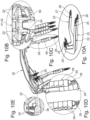
Figure 10A to 10E show an embodiment of thebridge 20 with detailed views of various construction elements ofbridge 20. Theelectrical connectors 23 shown inFig. 10A , which are used in the embodiment of thebridge 20, have the form of a hook. Eachelectrical connector 23 has a first contactingpin 24 at a firstfree end 25 and a second contactingpin 26 at a secondfree end 27. Theelectrical connectors 23 are stamped from a sheet material and placed into the mold for overmolding in a press-fit manner. - The
first end 41 or thesecond end 42 ofbridge 20 is shown inFig. 10B . Theelectrical connectors 23 form an integral part ofbridge 20, but are not completely overmolded by aplastic material 50. The overmolding step does not cover the first contactingpins 24 at the firstfree end 25 and the second contactingpins 26 at secondfree end 27 of electrical connector 23 (seeFigs. 10B and 10C ). -
Fig. 10D shows that theindividual legs 28 carry anovermolded section 29.Section 29, if anelectrical connector 23 is present, is formed aroundelectrical connector 23 and is a grip with a press geometry.Leg 28 hassection 29 formed even if anelectrical connector 23 is not present at a specific position.Section 29 having anassembly feature 46 in the form of the grip with the press geometry is necessary for assemblingbridge 20 tohousing 13. - The printed
circuit boards 11 with theIR diodes 12 are mounted to bridge 20 at a location of theillumination openings 22 of bridge 20 (seeFig. 10E ). The locating pin 39 (seeFig. 8A , the pair of locating pins 39) assist in aligning and assembling printedcircuit board 11 withIR diodes 12 to theillumination openings 22 ofbridge 20. -
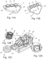
Figure 11A and 11B show various embodiments of the printedcircuit boards 11 forIR diodes 12. The printedcircuit boards 11 need to be adapted by means of appropriate holes or recesses 45 for press fits, and the position and number of pins may be customized according to requirements. - The printed
circuit boards 11 forIR diodes 12 haverecesses 45 formed which facilitate positioning of the printedcircuit board 11 at the defined position ofbridge 20. When positioning the printedcircuit board 11, the first contacting pins 24 (seeFig. 8A ) reach throughpassages 47 formed in the printedcircuit board 11. At least twopassages 47 are formed in the printedcircuit board 11. The number ofpassages 47 depends on the number ofelectrical connectors 23 that are part ofbridge 20. -
Figure 12 is a perspective view of thehousing 13 for thecamera 10 ofFig. 4 with detailed views (Figs. 12A to 12C ) of specific housing features. Preferably, thehousing 13 is suitable for aluminum die casting technology. Anassembly surface 30 for lens 4 (not shown) is placed on abase 31 ofhousing 13 and betweencooling geometries 32 ofhousing 13 and has a rounded shape (seeFig. 12A ). Each coolinggeometry 32 has a plurality offins 33 arranged in a fan shape and open to one side of each cooling geometry 32 (see alsoFig. 12B ). Anindividual mounting opening 34 is formed between two fins 33 (seeFig. 12C ). Theindividual mounting openings 34 are arranged on each coolinggeometry 32 such that they receive theindividual legs 28 of the embodiment ofbridge 20 as shown inFigs. 7A to 7B . With the coolinggeometries 32, the plurality offins 33 and the mountingopenings 34, geometries for cooling and thermal paste dispensing are formed. -
Figures 13A to 13F show the mounting sequence of abridge 20 together with other components of thevision camera 10 as shown inFig. 3 . In an initial step (seeFig. 13A ), the printedcircuit boards 11 withIR diodes 12 are mounted to each illumination opening 22 (seeFigs. 8A to 8C ) of abridge 20. In this process, the printedcircuit boards 11 withIR diodes 12 are electrically connected by thebridge 20. Thecircuit boards 11 are temporarily fixed to bridge 20 until the next step. In the next step (seeFig. 13B ),bridge 20 is assembled tohousing 13 together with the printedcircuit boards 11. Section 29 (seeFigs. 7A and 7B ), with a grip and press geometry of theindividual legs 28, provides an assembly feature on thehousing 13 that holdsbridge 20 in contact with thehousing 13. The contact (seeFig. 13C ) between thehousing 13 and the printedcircuit boards 11, which are located at thebridge 20, is established by pressingbridge 20 with printedcircuit boards 11 against the coolinggeometry 32. In addition, the printedcircuit board 16 for thecamera 10 is also brought into electrical contact with the second contacting pins 26 (seeFigs. 7A und 7B ) ofbridge 20. The coolinggeometry 32 ofhousing 13 matches thebridge 20. Next, as shown inFig. 13D , theoptical filter 15 is slid intohousing 13 and secured with ascrew 8. Furthermore, ISP printedcircuit board 17 is inserted intohousing 13.Cover 14 is fixed tohousing 13 together with fourfasteners 18. Thefasteners 18 are, for example, screws placed at each corner ofcover 14. The final assembly step is to assemblelens 4 throughopening 21 forlens 4 inbridge 20. After this final step, the assembly ofvision camera 10 is complete. -
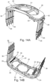
Figure 14A and 14B show two different perspective views of abridge 20 according to another embodiment of avision camera 10. As shown inFig. 6 ,bridge 20 is mounted tohousing 13 ofvision camera 10.Bridge 20 carries a one-piece leg 36 at thefirst end 41 and an opposite one-piece leg 36 at thesecond end 42.Bridge 20 is formed by an injection molding process, and the electrical connectors 23 (seeFig. 18A ) are completely embedded in the one-piece legs 36 ofbridge 20 made of a plastic material. However, the injection molding process is such that the first contactingpins 24 and the second contactingpins 26 of theelectrical connectors 23 are not covered by the plastic material ofbridge 20. The contacting pins 24 reach out to an inside 49 ofbridge 20. In addition, the locating pins 39 are formed on the inside 49 ofbridge 20. Each one-piece leg 36, in the embodiment shown here, has fourelectrical connectors 23 being part of the one-piece leg 36. As already mentioned in the description ofbridge 20 inFigs. 7A and 7B , the embodiment shown inFigs. 14A and 14B also has anopening 21 forlens 4 and anillumination opening 22 on both sides of theopening 21 forlens 4. -
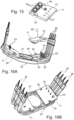
Figure 15 shows an embodiment of the printedcircuit board 11 forIR diodes 12 in conjunction withbridge 20 ofFigs. 14A and 14B . Printedcircuit board 11 has formed fourpassages 47 which can receive the second contactingpins 26 once the printedcircuit board 11 is positioned inbridge 20. -
Figure 16A and 16B show the installation process of printedcircuit board 11 to thebridge 20 as shown inFigs. 14A and 14B . Printedcircuit board 11 is lowered along anarrow 60 to the inside 49 toward theillumination opening 22 until printedcircuit board 11 coversillumination opening 22 and is then correctly positioned by means of the locating pins 39 and the first contactingpins 24 reach through thepassages 47 of printedcircuit board 11. -
Figure 17A and 17C show various embodiments of the printedcircuit boards 11 for theIR diodes 12. The embodiments differ by the number ofpassages 47 for the first contacting pins 24. InFig. 17A , the corresponding printedcircuit board 11 has fourpassages 47, meaning that the one-piece leg 36 has integrated fourelectrical connectors 23 and, consequently, four first contacting pins 24 (see, for example, the embodiment ofFigs. 16A and 16B ). InFig. 17B , the corresponding printedcircuit board 11 has twopassages 47, which means that the one-piece leg 36 has integrated twoelectrical connectors 23 and, consequently, two first contacting pins 24. InFig. 17C , the corresponding printedcircuit board 11 has threepassages 47, which means that the one-piece leg 36 has integrated twoelectrical connectors 23 and, consequently, three first contacting pins 24. The different embodiments of the printedcircuit boards 11 depend on the particular application. -
Figures 18A to 18D show bridge 20 ofFig. 14 with detailed views of various structural elements ofbridge 20.Electrical connector 23, which is part ofbridge 20, is shown inFig. 18A .Electrical connector 23 is also in the form of a hook. For example and as shown inFig. 18A ,electrical connector 23 is designed as a press-fit electrical connector having two bends initially placed in the mold (not shown). Eachelectrical connector 23 has a first contactingpin 24 at a firstfree end 25 and a second contactingpin 26 at a secondfree end 27. Theelectrical connectors 23 are placed in the mold for overmolding in a press-fit manner to form thebridge 20 with the one-piece legs 36.Fig. 18B shows ageometry 43, which is attached to each one-piece leg 36.Geometry 43 is used to mountbridge 20 with the attached printed circuit boards 11 (seeFig. 16B ) tohousing 13. Each one-piece leg 36 has anassembly feature 45 in asection 29 that is used to mountbridge 20 to housing 13 (seeFig. 18C ). Preferably,geometry 43 is a grip and press geometry as previously described, i.e., which cooperates with mountingopening 34 to mountbridge 20 tohousing 13.Fig. 18D shows a section through the inside 49 ofbridge 20. The locatingpin 39 on the inside 49 is used to position printed circuit board 11 (seeFig. 16B ). -
Figure 19 is a perspective view of thehousing 13 forcamera 10 ofFig. 6 with detailed views (Figs. 19A to 19C ) of specific housing features. Preferably,housing 13 is suitable for aluminum die casting technology. Anassembly surface 30 for lens 4 (not shown), which has a rounded shape (seeFig. 19A ), is placed betweencooling geometries 32 ofhousing 13. Each coolinggeometry 32 has a plurality ofparallel fins 33, which are open to one side of each coolinggeometry 32. Following theparallel fins 33, a mounting opening 34 (seeFig. 19C ) with an elongated shape is formed inhousing 13. The mountingopening 34 ofhousing 13 cooperates withassembly feature 45 insection 29 of the one-piece leg 36 ofbridge 20. The two mountingopenings 34 each receive the one-piece leg 36 ofbridge 20 to mountbridge 20 tohousing 13. With the coolinggeometries 32, the plurality offins 33 and the mountingopenings 34, geometries for cooling and thermal paste dispensing are formed. -
Figure 20A to 20F show the mounting sequence ofbridge 20 together with other components ofvision camera 10 as shown inFig. 5 . In an initial step (seeFig. 20A ), the printedcircuit boards 11 withIR diodes 12 are mounted to each illumination opening 22 of a bridge 20 (seeFigs. 16A to 16b ). In this process, the printedcircuit boards 11 withIR diodes 12 are electrically connected bybridge 20. Thecircuit boards 11 are temporarily fixed to bridge 20 until the next step. In the next step (seeFig. 20B ),bridge 20 is inserted into the coolinggeometries 32 ofhousing 13 together with the printedcircuit boards 11. Section 29 (seeFig. 18C ) withassembly feature 45 of one-piece leg 36 is mounted to thehousing 13 and holdsbridge 20 in contact withhousing 13. The contact (seeFig. 20C ) between the coolinggeometries 32 ofhousing 13 and the printedcircuit boards 11, which are located onbridge 20, is established by pressing thebridge 20 with printedcircuit boards 11 against the coolinggeometry 32. Also, the printedcircuit board 16 for thecamera 10 is brought in electrical contact with the second contacting pins 26 (seeFigs. 16A und 16B ) ofbridge 20. Next, as shown inFig. 20D , theoptical filter 15 is slid into thehousing 13 and secured with ascrew 8. Further, the ISP printedcircuit board 17 is placed inhousing 13.Cover 14 is attached tohousing 13 together with fourfasteners 18.Fasteners 18 are, for example, screws placed at each corner ofcover 14. The final assembly step is to assemblelens 4 throughopening 21 forlens 4 in thebridge 20. After this final step, the assembly ofvision camera 10 is completed. - It is believed that the present disclosure and many of its attendant advantages will be understood by the foregoing description, and it will be apparent that various changes may be made in the form, construction, number and arrangement of the components without departing from the disclosed subject matter or without sacrificing all of its material advantages. The form described is merely explanatory, and it is the intention of the following claims to encompass and include such changes. Accordingly, the scope of the invention should be limited only by the claims appended hereto.
-
- 1
- driver monitoring system
- 2
- motor vehicle
- 3
- windshield
- 4
- lens
- 5
- driver
- 8
- screw
- 10
- camera
- 11
- printed circuit board
- 12
- IR diode
- 13
- housing
- 14
- cover
- 15
- filter
- 16
- printed circuit board for the camera
- 17
- ISP printed circuit board
- 18
- fastener
- 20
- bridge
- 21
- opening for lens
- 22
- illumination opening
- 23
- electrical connector
- 24
- first contacting pin
- 25
- first free end
- 26
- second contacting pin
- 27
- second free end
- 28
- leg
- 29
- section
- 30
- assembly surface
- 31
- base
- 32
- cooling geometry
- 33
- fin
- 34
- mounting opening
- 36
- one-piece leg
- 39
- locating pin
- 41
- first end
- 42
- second end
- 43
- geometry
- 45
- recess
- 46
- assembly feature
- 47
- passage
- 49
- inside
- 50
- plastic material
- 60
- arrow
Claims (15)
- A vision camera (10) for a driver monitoring system (1), comprisinga housing (13), anda cover (14),the housing (13) carrying a lens (4), a printed circuit board (11) with IR diodes (12) on either side of the lens (4), and a printed circuit board (16) for the camera (10) positioned in the housing (13),characterized bya bridge (20) having an opening (21) for the lens (4) and an illumination opening (22) on either side of the opening (21) for the lens (4); anda plurality of electrical connectors (23) that are an integral part of the bridge (20) and electrically contact the printed circuit board (11) with IR diodes (12) and the printed circuit board (16) for the camera (10) once the bridge (20) is mounted to the housing (13).
- The vision camera (10) as claimed in claim 1, wherein inside the housing (13), an ISP printed circuit board (17) is electrically connected to the printed circuit board (16) for the camera (10).
- The vision camera (10) as claimed in any one of the preceding claims, wherein each of the plurality electrical connectors (23) of the bridge (20) is in the form of a hook having a first contacting pin (24) at a first free end (25) and a second contacting pin (26) at a second free end (27).
- The vision camera (10) as claimed in claim 3, wherein the bridge (20) comprises an injection molded plastic material having a plurality of at least partially embedded and overmolded electrical connectors (23) provided at a first end (41) and a second end (42) of the bridge (20).
- The vision camera (10) as claimed in claim 4, wherein the first contacting pins (24) of the electrical connectors (23), embedded in the bridge (20), electrically contact the printed circuit board (11) with the IR diodes (12), and the second contacting pins (26) of the electrical connectors (23), embedded in the bridge (20), electrically contact the printed circuit board (16) for the camera (10).
- The vision camera (10) as claimed in any one of the preceding claims, wherein the housing (13) has formed an assembly surface (30) for the lens (4), two cooling geometries (32) located laterally the assembly surface (30) and at least one mounting feature (34) for the bridge (20) located at each cooling geometry (32).
- The vision camera (10) as claimed in any one of the preceding claims, wherein individual legs (28) are formed at a first end (41) and a second end (42) of the bridge (20), wherein at least two of the embedded and overmolded electrical connectors (23) are part of the individual legs (28), and each cooling geometry (32) has formed a plurality of fins (33) thereon, wherein an individual mounting opening (34) is formed between each of two successive fins (33) arranged to receive the individual legs (28) of the bridge (20).
- The vision camera (10) as claimed in claim 7, wherein each of the individual legs (28) comprises a section (29) with a grip and press geometry that cooperates with the mounting opening (34).
- The vision camera (10) as claimed in any one of claims 1 to 6, wherein at a first end (41) and a second end (42) of the bridge (20), the at least two embedded and overmolded electrical connectors (23) together form a one-piece leg (36), and each cooling geometry (32) has formed a plurality of fins (33) and an elongated mounting opening (38), which is arranged to receive the one-piece leg (36) of the bridge (20).
- The vision camera (10) as claimed in claim 9, wherein each one-piece leg (36) has a section (29) with an assembly feature (45) cooperating with the mounting opening (38).
- A vision camera arrangement for a driver monitoring system (1) comprising a vision camera (10) according to any one of the preceding claims.
- A method for assembling a vision camera (10) for a driver monitoring system comprising the steps of:mounting a printed circuit board (11) with IR diodes (12) to each illumination opening (22) of a bridge (20) and electrically connecting the printed circuit board (11) with IR diodes (12);attaching the bridge (20) with the printed circuit board (11) with IR diodes (12) to the housing (13);inserting a printed circuit board (16) for the camera (10) into the housing (13) and electrically connecting the printed circuit board (16) to the bridge (20);sliding an optical filter (9) into the housing (13) and securing the optical filter (9) in the housing (13);placing an ISP printed circuit board (17) in the housing and electrically connecting it to the printed circuit board (16) for the camera (10), and attaching a cover (14) to the housing (13); andassembling a lens (4) into the housing (13).
- The method as claimed in claim 12, wherein the electric connection of the printed circuit board (11) with IR diodes (12) is established by means of first contacting pins (24).
- The method as claimed in claim 12, wherein the electric connection of the printed circuit board (16) for the camera (10) is established by means of second contacting pins (26).
- The method as claimed in any one of claims 12 to 14, wherein the bridge (20) comprises sections (29) having a grip and press geometry for mounting the bridge (20) to the housing (13).
Priority Applications (1)
| Application Number | Priority Date | Filing Date | Title |
|---|---|---|---|
| EP23177152.8A EP4475523B1 (en) | 2023-06-05 | 2023-06-05 | Vision camera for a driver monitoring system and method for assembling a vision camera |
Applications Claiming Priority (1)
| Application Number | Priority Date | Filing Date | Title |
|---|---|---|---|
| EP23177152.8A EP4475523B1 (en) | 2023-06-05 | 2023-06-05 | Vision camera for a driver monitoring system and method for assembling a vision camera |
Publications (2)
| Publication Number | Publication Date |
|---|---|
| EP4475523A1 true EP4475523A1 (en) | 2024-12-11 |
| EP4475523B1 EP4475523B1 (en) | 2025-12-10 |
Family
ID=86693090
Family Applications (1)
| Application Number | Title | Priority Date | Filing Date |
|---|---|---|---|
| EP23177152.8A Active EP4475523B1 (en) | 2023-06-05 | 2023-06-05 | Vision camera for a driver monitoring system and method for assembling a vision camera |
Country Status (1)
| Country | Link |
|---|---|
| EP (1) | EP4475523B1 (en) |
Citations (2)
| Publication number | Priority date | Publication date | Assignee | Title |
|---|---|---|---|---|
| US20170264797A1 (en) * | 2014-08-11 | 2017-09-14 | Robert Bosch Gmbh | Driver monitoring system in a motor vehicle |
| EP3982197A1 (en) * | 2020-10-08 | 2022-04-13 | Veoneer Sweden AB | Driver monitoring system based on vision camera |
-
2023
- 2023-06-05 EP EP23177152.8A patent/EP4475523B1/en active Active
Patent Citations (2)
| Publication number | Priority date | Publication date | Assignee | Title |
|---|---|---|---|---|
| US20170264797A1 (en) * | 2014-08-11 | 2017-09-14 | Robert Bosch Gmbh | Driver monitoring system in a motor vehicle |
| EP3982197A1 (en) * | 2020-10-08 | 2022-04-13 | Veoneer Sweden AB | Driver monitoring system based on vision camera |
Also Published As
| Publication number | Publication date |
|---|---|
| EP4475523B1 (en) | 2025-12-10 |
Similar Documents
| Publication | Publication Date | Title |
|---|---|---|
| US5629574A (en) | Control interface device for an electric motor | |
| EP2180557A1 (en) | LED string light engine | |
| JP3790933B2 (en) | Electronic module | |
| US4169282A (en) | Multiphase full-wave rectifier assembly | |
| CN115135564B (en) | Drive unit for an electric power steering system of a motor vehicle | |
| US20050189829A1 (en) | EMI suppression in permanent magnet DC motors having PCB outside motor in connector and overmolded | |
| US6479916B1 (en) | Method and apparatus for mounting electronic motor controls | |
| US5685728A (en) | Rotary connector device | |
| JP4861366B2 (en) | LED lamp module and lamp module assembly | |
| EP0966075A1 (en) | Appliance connector and production method thereof | |
| US7695306B2 (en) | Electronic part-connecting structure | |
| US7025485B2 (en) | High mount stop lamp with printed circuit board | |
| EP4475523B1 (en) | Vision camera for a driver monitoring system and method for assembling a vision camera | |
| US6929487B1 (en) | Terminal block arrangement for a printed circuit board in a smart connector | |
| US5653018A (en) | Method for the manufacture of an electric appliance | |
| US10804662B2 (en) | Device for driving motor | |
| KR19990082044A (en) | Electric device | |
| US6979213B1 (en) | Electrical junction box with sliding lock lever | |
| SE528602C2 (en) | Key and way of producing such key | |
| US20240322656A1 (en) | Diode carrier arrangement, overvoltage protection device with the same, motor vehicle component with the same and manufacturing method for a diode carrier arrangement | |
| US6257903B1 (en) | Self-docking electrical connector | |
| US20200366014A1 (en) | Circuit Board With a Plug Connection | |
| CN107438921B (en) | Brush holder adjuster, method of manufacturing same, and alternator equipped with same | |
| US20010031584A1 (en) | Hybrid plug housing and process for its production | |
| US6237220B1 (en) | Method for manufacturing elastic strips, pin holders and similar plug-in connectors |
Legal Events
| Date | Code | Title | Description |
|---|---|---|---|
| PUAI | Public reference made under article 153(3) epc to a published international application that has entered the european phase |
Free format text: ORIGINAL CODE: 0009012 |
|
| STAA | Information on the status of an ep patent application or granted ep patent |
Free format text: STATUS: THE APPLICATION HAS BEEN PUBLISHED |
|
| AK | Designated contracting states |
Kind code of ref document: A1 Designated state(s): AL AT BE BG CH CY CZ DE DK EE ES FI FR GB GR HR HU IE IS IT LI LT LU LV MC ME MK MT NL NO PL PT RO RS SE SI SK SM TR |
|
| STAA | Information on the status of an ep patent application or granted ep patent |
Free format text: STATUS: REQUEST FOR EXAMINATION WAS MADE |
|
| 17P | Request for examination filed |
Effective date: 20250604 |
|
| GRAP | Despatch of communication of intention to grant a patent |
Free format text: ORIGINAL CODE: EPIDOSNIGR1 |
|
| STAA | Information on the status of an ep patent application or granted ep patent |
Free format text: STATUS: GRANT OF PATENT IS INTENDED |
|
| INTG | Intention to grant announced |
Effective date: 20250711 |
|
| GRAS | Grant fee paid |
Free format text: ORIGINAL CODE: EPIDOSNIGR3 |
|
| GRAA | (expected) grant |
Free format text: ORIGINAL CODE: 0009210 |
|
| STAA | Information on the status of an ep patent application or granted ep patent |
Free format text: STATUS: THE PATENT HAS BEEN GRANTED |
|
| AK | Designated contracting states |
Kind code of ref document: B1 Designated state(s): AL AT BE BG CH CY CZ DE DK EE ES FI FR GB GR HR HU IE IS IT LI LT LU LV MC ME MK MT NL NO PL PT RO RS SE SI SK SM TR |
|
| REG | Reference to a national code |
Ref country code: CH Ref legal event code: F10 Free format text: ST27 STATUS EVENT CODE: U-0-0-F10-F00 (AS PROVIDED BY THE NATIONAL OFFICE) Effective date: 20251210 Ref country code: GB Ref legal event code: FG4D |
|
| REG | Reference to a national code |
Ref country code: DE Ref legal event code: R096 Ref document number: 602023009455 Country of ref document: DE |
|
| REG | Reference to a national code |
Ref country code: IE Ref legal event code: FG4D |
|
| P01 | Opt-out of the competence of the unified patent court (upc) registered |
Free format text: CASE NUMBER: UPC_APP_0001106_4475523/2026 Effective date: 20260113 |
|
| PG25 | Lapsed in a contracting state [announced via postgrant information from national office to epo] |
Ref country code: ES Free format text: LAPSE BECAUSE OF FAILURE TO SUBMIT A TRANSLATION OF THE DESCRIPTION OR TO PAY THE FEE WITHIN THE PRESCRIBED TIME-LIMIT Effective date: 20251210 |
|
| REG | Reference to a national code |
Ref country code: LT Ref legal event code: MG9D |
|
| PG25 | Lapsed in a contracting state [announced via postgrant information from national office to epo] |
Ref country code: NO Free format text: LAPSE BECAUSE OF FAILURE TO SUBMIT A TRANSLATION OF THE DESCRIPTION OR TO PAY THE FEE WITHIN THE PRESCRIBED TIME-LIMIT Effective date: 20260310 |
|
| PG25 | Lapsed in a contracting state [announced via postgrant information from national office to epo] |
Ref country code: FI Free format text: LAPSE BECAUSE OF FAILURE TO SUBMIT A TRANSLATION OF THE DESCRIPTION OR TO PAY THE FEE WITHIN THE PRESCRIBED TIME-LIMIT Effective date: 20251210 Ref country code: HR Free format text: LAPSE BECAUSE OF FAILURE TO SUBMIT A TRANSLATION OF THE DESCRIPTION OR TO PAY THE FEE WITHIN THE PRESCRIBED TIME-LIMIT Effective date: 20251210 |
|
| REG | Reference to a national code |
Ref country code: NL Ref legal event code: MP Effective date: 20251210 |
|
| PG25 | Lapsed in a contracting state [announced via postgrant information from national office to epo] |
Ref country code: RS Free format text: LAPSE BECAUSE OF FAILURE TO SUBMIT A TRANSLATION OF THE DESCRIPTION OR TO PAY THE FEE WITHIN THE PRESCRIBED TIME-LIMIT Effective date: 20260310 |
|
| PG25 | Lapsed in a contracting state [announced via postgrant information from national office to epo] |
Ref country code: LV Free format text: LAPSE BECAUSE OF FAILURE TO SUBMIT A TRANSLATION OF THE DESCRIPTION OR TO PAY THE FEE WITHIN THE PRESCRIBED TIME-LIMIT Effective date: 20251210 |
|
| PG25 | Lapsed in a contracting state [announced via postgrant information from national office to epo] |
Ref country code: BG Free format text: LAPSE BECAUSE OF FAILURE TO SUBMIT A TRANSLATION OF THE DESCRIPTION OR TO PAY THE FEE WITHIN THE PRESCRIBED TIME-LIMIT Effective date: 20251210 |