EP4475460A1 - Optical communication system, branch station, and communication method - Google Patents
Optical communication system, branch station, and communication method Download PDFInfo
- Publication number
- EP4475460A1 EP4475460A1 EP22924790.3A EP22924790A EP4475460A1 EP 4475460 A1 EP4475460 A1 EP 4475460A1 EP 22924790 A EP22924790 A EP 22924790A EP 4475460 A1 EP4475460 A1 EP 4475460A1
- Authority
- EP
- European Patent Office
- Prior art keywords
- signal
- station
- side equipment
- extension
- downstream
- Prior art date
- Legal status (The legal status is an assumption and is not a legal conclusion. Google has not performed a legal analysis and makes no representation as to the accuracy of the status listed.)
- Pending
Links
Images



Classifications
-
- H—ELECTRICITY
- H04—ELECTRIC COMMUNICATION TECHNIQUE
- H04J—MULTIPLEX COMMUNICATION
- H04J14/00—Optical multiplex systems
- H04J14/02—Wavelength-division multiplex systems
- H04J14/0227—Operation, administration, maintenance or provisioning [OAMP] of WDM networks, e.g. media access, routing or wavelength allocation
- H04J14/0254—Optical medium access
- H04J14/02764—Multiplex arrangements for radio-frequency networks access; policies therefor
-
- H—ELECTRICITY
- H04—ELECTRIC COMMUNICATION TECHNIQUE
- H04J—MULTIPLEX COMMUNICATION
- H04J14/00—Optical multiplex systems
- H04J14/02—Wavelength-division multiplex systems
- H04J14/0227—Operation, administration, maintenance or provisioning [OAMP] of WDM networks, e.g. media access, routing or wavelength allocation
-
- H—ELECTRICITY
- H04—ELECTRIC COMMUNICATION TECHNIQUE
- H04J—MULTIPLEX COMMUNICATION
- H04J14/00—Optical multiplex systems
- H04J14/02—Wavelength-division multiplex systems
- H04J14/03—WDM arrangements
- H04J14/0307—Multiplexers; Demultiplexers
Definitions
- the present invention relates to an optical communication system, an extension station, and a communication method.
- Radio waves in a millimeter-wave band are attracting attention because the radio waves can be transmitted at high speeds. However, because radio waves in the millimeter-wave band have large propagation loss, it is necessary to install wireless base stations at high density.
- Analog RoF is technology in which an optical signal is intensity-modulated with a radio signal and the intensity-modulated optical signal is transmitted through an optical fiber, and can extract an original radio signal by performing optical-to-electrical (O/E) conversion for the transmitted optical signal.
- O/E optical-to-electrical
- wireless base stations can be separated into an aggregate station that performs signal processing and an extension station having an antenna function, and a signal processing function can be integrated into the aggregate station. Thereby, it is possible to simplify and more easily install the extension station.
- Non-Patent Document 2 discloses that the aggregate station and the extension stations are connected according to a cascade configuration so that the extension stations are installed more easily.
- the extension station according to Non-Patent Document 2 distributes an optical signal using an optical splitter, and then demultiplexes the optical signal to extract an optical signal having a desired wavelength.
- the optical splitter causes the loss of the optical signal and the magnitude of the optical signal received by the extension station away from the aggregate station may be reduced.
- the present invention provides an optical communication system, an extension station, and a communication method capable of suppressing the loss of an optical signal.
- an optical communication system having an aggregate station at a head and a plurality of extension stations connected in series, wherein each of the plurality of extension stations demultiplexes a signal received from upstream-side equipment into a first demultiplexed signal having a locally allocated wavelength and a second demultiplexed signal having another wavelength and transmits the second demultiplexed signal to downstream-side equipment, and wherein each of the plurality of extension stations multiplexes a signal received from the downstream-side equipment and a locally processed signal and transmits a multiplexing result to the upstream-side equipment.
- an extension station in an optical communication system having an aggregate station at a head and a plurality of extension stations connected in series, wherein the extension station demultiplexes a signal received from upstream-side equipment into a first demultiplexed signal having a locally allocated wavelength and a second demultiplexed signal having another wavelength and transmits the second demultiplexed signal to downstream-side equipment, and wherein the extension station multiplexes a signal received from the downstream-side equipment and a locally processed signal and transmits a multiplexing result to the upstream-side equipment.
- a communication method of an extension station in an optical communication system having an aggregate station at a head and a plurality of extension stations connected in series, the communication method including steps of: demultiplexing a signal received from upstream-side equipment into a first demultiplexed signal having a locally allocated wavelength and a second demultiplexed signal having another wavelength and transmitting the second demultiplexed signal to downstream-side equipment, and multiplexing a signal received from the downstream-side equipment and a locally processed signal and transmitting a multiplexing result to the upstream-side equipment.
- An optical communication system, an extension station, and a communication method according to the present invention can suppress the loss of an optical signal.
- FIG. 1 is a diagram showing a configuration of an optical communication system 1 in which an aggregate station 10 and extension stations 11 are connected through a cascade configuration.
- the optical communication system 1 has one aggregate station 10 and N extension stations 11 (N is an integer of 2 or more).
- the optical communication system 1 has the aggregate station 10 at a head and the N extension stations 11 connected in series.
- each extension station 11 is referred to as an i th extension station 11-i (i is an integer satisfying 1 ⁇ i ⁇ N) when the N extension stations 11 are distinguished, but is simply referred to as an extension station 11 when features common to all i th extension stations 11-i are described.
- the ordinal number i is equal to the number of hops from the aggregate station 10.
- a direction from the aggregate station 10 to the extension station 11 is referred to as a downstream direction and a direction from the extension station 11 to the aggregate station 10 is referred to as an upstream direction.
- the aggregate station 10 transmits a downlink optical signal generated by performing electrical-to-optical (E/O) conversion for a generated radio signal to the first extension station 11-1.
- the first extension station 11-1 demultiplexes the received downlink optical signal, transmits a partial optical signal to the second extension station 11-2, locally processes the remaining optical signal, and transmits a radio signal in accordance with the optical signal.
- the first extension station 11-1 for example, radiates a radio signal obtained by performing optical-to-electrical (O/E) conversion for an optical signal to a space via an antenna.
- Second to (N-1) th extension stations 11-2 to 11-(N-1) also perform operations similar to that of the first extension station 11-1.
- the i th extension station 11-i demultiplexes the optical signal received from an (i-1) th extension station 11-(i-1), which upstream equipment, and transmits a partial optical signal to an (i+1) th extension station 11-(i+1), which is downstream equipment.
- the i th extension station 11-i (i is an integer satisfying 2 ⁇ i ⁇ N-1), for example, generates an uplink optical signal by performing E/O conversion for a radio signal received via an antenna.
- the i th extension station 11-i multiplexes an optical signal received from the downstream equipment and an uplink optical signal and transmits a merging result to the upstream equipment. That is, the i th extension station 11-i multiplexes the optical signal received from the (i+1) th extension station 11-(i+1) and an optical signal obtained by converting a locally received radio signal and transmits an optical signal obtained in the multiplexing process to the (i-1) th extension station 11-(i-1).
- the optical signal transmitted from the aggregate station 10 descends to the first extension station 11-1 and the second extension station 11-2 and finally reaches the N th extension station 11-N. Moreover, the optical signal transmitted from the N th extension station 11-N ascends to the (N-1) th extension station 11-(N-1) and finally reaches the aggregate station 10.
- the aggregate station 10 performs O/E conversion for the optical signal arriving thereat and acquires a radio signal.
- the radio signal for example, is subjected to signal processing.
- the aggregate station 10 is located at the head and the N extension stations 11 are connected in series.
- a radio signal received in the extension station 11 is converted into an optical signal without signal processing in the extension station 11 and aggregated in the aggregate station 10.
- the optical signal aggregated in the aggregate station 10 is converted into a radio signal and the radio signal received by the extension station 11 is extracted. Because the extension station 11 does not need to include a configuration in which signal processing of a radio signal is performed, the extension station 11 can be easily implemented.
- the aggregate station 10 and the first extension station 11-1 and the i th extension station 11-i and the (i+1) th extension station 11-(i+1) (i is an integer satisfying 1 ⁇ i ⁇ N-1) are connected by two transmission paths, i.e., a downstream transmission path 12 and an upstream transmission path 13.
- the transmission path is, for example, an optical fiber.
- FIG. 2 is a diagram showing a configuration of the aggregate station 10 according to a first embodiment.
- the aggregate station 10 includes a transmission unit 100, an E/O conversion unit 101, a multiplexing unit 102, a demultiplexing unit 103, an O/E conversion unit 104, and a reception unit 105.
- the aggregate station 10 includes N transmission units 100, N E/O conversion units 101, N O/E conversion units 104, and N reception units 105, wherein N is the same as the number of extension stations 11.
- the transmission units 100 are referred to as a first transmission unit 100-1, a second transmission unit 100-2, ..., and an N th transmission unit 100-N.
- the E/O conversion units 101 are referred to as a first E/O conversion unit 101-1, a second E/O conversion unit 101-2, ..., and an N th E/O conversion unit 101-N.
- the O/E conversion units 104 are referred to as a first O/E conversion unit 104-1, a second O/E conversion unit 104-2, ..., and an N th O/E conversion unit 104-N.
- the reception units 105 are referred to as a first reception unit 105-1, a second reception unit 105-2, ..., and an N th reception unit 105-N.
- An i th transmission unit 100-i (i is an integer satisfying 1 ⁇ i ⁇ N) transmits an electrical signal to an i th E/O conversion unit 101-i.
- the i th E/O conversion unit 101-i (i is an integer satisfying 1 ⁇ i ⁇ N) converts the received electrical signal into an optical signal and transmits the optical signal to the multiplexing unit 102.
- the wavelengths of the optical signals transmitted to the multiplexing unit 102 by the i th E/O conversion unit 101-i are different.
- the wavelength of the optical signal transmitted by the i th E/O conversion unit 101-i is denoted by ⁇ DLi and differs according to each E/O conversion unit 101.
- the optical signal transmitted by the i th E/O conversion unit 101-i is intended to finally reach the i th extension station 11-i.
- the aggregate station 10 can switch the transmission unit 100 from which the electrical signal is transmitted, thereby switching the extension station 11 at which the transmitted optical signal finally arrives. Thereby, the aggregate station 10 can perform a handover or switch between whether or not to cause the extension station 11 to transmit/receive a signal.
- the multiplexing unit 102 multiplexes optical signals received from the E/O conversion units 101 and transmits a multiplexing result to the first extension station 11-1.
- the demultiplexing unit 103 demultiplexes an optical signal received from the first extension station 11-1 and transmits the demultiplexed optical signal to the O/E conversion units 104.
- a wavelength of the optical signal transmitted by the demultiplexing unit 103 to the i th O/E conversion unit 104-i is denoted by ⁇ ULi and differs for each O/E conversion unit 104.
- the optical signal having the wavelength ⁇ ULi is an optical signal transmitted from the i th extension station 11-i.
- the i th O/E conversion unit 104-i (i is an integer satisfying 1 ⁇ i ⁇ N) converts the received optical signal into an electrical signal and transmits the electrical signal to the i th reception unit 105-i.
- the i th reception unit 104-5 (i is an integer satisfying 1 ⁇ i ⁇ N) receives the electrical signal from the i th O/E conversion unit 104-i.
- the aggregate station 10 and the first extension station 11-1 are connected by two transmission paths, i.e., the downstream transmission path 12-1 and the upstream transmission path 13-1.
- the downstream transmission path 12-1 is connected to the multiplexing unit 102 and transmits an optical signal obtained in a multiplexing process of the multiplexing unit 102 to the first extension station 11-1.
- the upstream transmission path 13-1 is connected to the demultiplexing unit 103 and transmits an optical signal from the first extension station 11-1 to the demultiplexing unit 103.
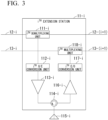
- FIG. 3 is a diagram showing a configuration of the i th extension station 11-i (i is an integer satisfying 1 ⁇ i ⁇ N) according to the first embodiment.
- the i th extension station 11-i includes an i th demultiplexing unit 111-i, an i th O/E conversion unit 112-i, an i th transmission amplifier 113-i, an i th circulator 114-i, an i th antenna 115-i, an i th reception amplifier 116-i, an i th E/O conversion unit 117-i, and an i th multiplexing unit 118-i.
- the i th demultiplexing unit 111-i, the i th O/E conversion unit 112-i, the i th transmission amplifier 113-i, the i th circulator 114-i, the i th antenna 115-i, the i th reception amplifier 116-i, the i th E/O conversion unit 117-i, and the i th multiplexing unit 118-i are referred to as the demultiplexing unit 111, the O/E conversion unit 112, the transmission amplifier 113, the circulator 114, the antenna 115, the reception amplifier 116, the E/O conversion unit 117, and the multiplexing unit 118, respectively, when features not depending upon the position of the extension station 11 are described.
- the i th demultiplexing unit 111-i demultiplexes an optical signal received from the upstream equipment via the downstream transmission path 12-i into an optical signal having a wavelength ⁇ DLi and an optical signal having another wavelength.
- the i th demultiplexing unit 111-i transmits the optical signal having the wavelength ⁇ DLi to the i th O/E conversion unit 112-i and transmits the optical signal having the other wavelength to the (i+1) th extension station 11-(i+1) via a downstream transmission path 12-(i+1).
- the i th O/E conversion unit 112-i converts the optical signal received from the i th demultiplexing unit 111-i into an electrical signal and transmits the electrical signal to the i th transmission amplifier 113-i.
- the i th transmission amplifier 113-i amplifies the electrical signal received from the i th O/E conversion unit 112-i and transmits the amplified electrical signal to the i th circulator 114-i.
- the i th circulator 114-i transmits an electrical signal received from the i th transmission amplifier 113-i to the i th antenna 115-i. Moreover, the i th circulator 114-i transmits the electrical signal received from the i th antenna 115-i to the i th reception amplifier 116-i.
- the i th antenna 115-i radiates an electrical signal received from the i th circulator 114-i to a space. Moreover, the i th antenna 115-i transmits the received electrical signal to the i th circulator 114-i.
- the i th reception amplifier 116-i amplifies the electrical signal received from the i th circulator 114-i and transmits the amplified electrical signal to the i th E/O conversion unit 117-i.
- the i th E/O conversion unit 117-i converts an electrical signal received from the i th reception amplifier 116-i into an optical signal having a wavelength ⁇ ULi and transmits the optical signal to the i th multiplexing unit 118-i.
- the i th multiplexing unit 118-i multiplexes the optical signal received from the i th E/O conversion unit 117-i and the optical signal received from the (i+1) th extension station 11-(i+1) via an upstream transmission path 13-(i+1) and transmits an optical signal obtained in the multiplexing process to the upstream equipment via the upstream transmission path 13-i.
- the first multiplexing unit 118-1 transmits an optical signal obtained in the multiplexing process to the aggregate station 10 and the i th multiplexing unit 118-i (i is an integer satisfying 2 ⁇ i ⁇ N-1) transmits an optical signal obtained in the multiplexing process to the (i-1) th extension station 11-(i-1).
- Each of the i th demultiplexing unit 111-i and the i th multiplexing unit 118-i are, for example, a thin film filter or a fiber Bragg grating (FBG).
- the i th demultiplexing unit 111-i demultiplexes the optical signal received from the upstream equipment and extracts an optical signal corresponding to its own station by extracting a signal having the wavelength ⁇ DLi from the demultiplexed optical signal.
- the i th multiplexing unit 118-i multiplexes the optical signal having the wavelength ⁇ ULi received from the i th E/O conversion unit 117-i and the optical signal transmitted from the (i+1) th extension station 11-(i+1) and transmits an optical signal obtained in the multiplexing process to the upstream equipment.
- the optical signal having the wavelength ⁇ ULi transmitted from the i th E/O conversion unit 117-i is finally received by the i th reception unit 105-i.
- the N th extension station 11-N has substantially the same configuration as the i th extension station 11-i (i is an integer satisfying 1 ⁇ i ⁇ N-1), but may not include a demultiplexing unit and a multiplexing unit.
- the two transmission paths connecting the extension station 11 and other equipment are connected to the demultiplexing unit 111 and the multiplexing unit 118 in the configuration of the extension station 11.
- FIG. 4 is a flowchart showing a transmission method of the aggregate station 10.
- the transmission unit 100 transmits an electrical signal to the E/O conversion unit 101 (step S1).
- the E/O conversion unit 101 converts the electrical signal into an optical signal (step S2).
- the multiplexing unit 102 multiplexes optical signals (step S3). An optical signal after the multiplexing is transmitted to the first extension station 11-1.
- FIG. 5 is a flowchart showing a reception method of the aggregate station 10.
- the demultiplexing unit 103 demultiplexes an optical signal received from the first extension station 11-1 (step S11).
- the O/E conversion unit 104 converts the optical signal into an electrical signal (step S12).
- the reception unit 105 receives the electrical signal (step S13).
- FIG. 6 is a flowchart showing a communication method in which the extension station 11 communicates with upstream equipment.
- the demultiplexing unit 111 demultiplexes an optical signal received from the upstream equipment (step S21). Optical signals obtained in the demultiplexing process are transmitted to the O/E conversion unit 112 and the downstream equipment.
- the O/E conversion unit 112 converts the optical signal into an electrical signal (step S22).
- the transmission amplifier 113 amplifies the electrical signal (step S23).
- the electrical signal is radiated from the antenna 115 via the circulator 114 (step S24).
- FIG. 7 is a flowchart showing a communication method in which the extension station 11 communicates with downstream equipment.
- the antenna 115 receives an electrical signal (step S31).
- the electrical signal is amplified by the reception amplifier 116 via the circulator 114 (step S32).
- the E/O conversion unit 117 converts the electrical signal into an optical signal (step S33).
- the multiplexing unit 118 multiplexes optical signals (step S34). An optical signal obtained in the multiplexing process is transmitted to the upstream equipment.
- the extension station 11 does not include an optical splitter. Thereby, the loss of the optical signal can be suppressed.
- the wavelength of the optical signal transmitted by the transmission unit 100 and the wavelength of the optical signal received by the reception unit 105 may be the same.
- pieces of equipment of an aggregate station 10 and an extension station 11 are connected by a single transmission path 14. That is, a signal transmitted to an upstream side by the extension station 11 and a signal received from the upstream side are transmitted through the same transmission path and a signal transmitted to a downstream side by the extension station 11 and a signal received from the downstream side are transmitted through the same transmission path.
- FIG. 8 is a diagram showing a configuration of the aggregate station 10 according to the second embodiment.
- the aggregate station 10 according to the second embodiment includes a multiplexing/demultiplexing unit 106 instead of the multiplexing unit 102 and the demultiplexing unit 103.
- the multiplexing/demultiplexing unit 106 multiplexes optical signals received from E/O conversion units 101 and transmits an optical signal obtained in the multiplexing process to a first extension station 11-1.
- the multiplexing/demultiplexing unit 106 demultiplexes an optical signal received from the first extension station 11-1 and transmits optical signals obtained in the demultiplexing process to O/E conversion units 104.
- a wavelength of the optical signal transmitted to an i th O/E conversion unit 104-i by the multiplexing/demultiplexing unit 106 is denoted by ⁇ ULi and differs according to each O/E conversion unit 104. That is, the multiplexing/demultiplexing unit 106 functions as both the multiplexing unit 102 and the demultiplexing unit 103.
- the aggregate station 10 and the first extension station 11-1 according to the second embodiment are connected by a single transmission path.
- the single transmission path connecting the aggregate station 10 and the first extension station 11-1 is connected to the multiplexing/demultiplexing unit 106 in the configuration of the aggregate station 10.
- FIG. 9 is a diagram showing the configuration of the i th extension station 11-i (i is an integer satisfying 1 ⁇ i ⁇ N) according to the second embodiment.
- the i th extension station 11-i according to the second embodiment includes an i th upstream-side circulator 110-i and an i th downstream-side circulator 119-i in addition to the i th extension station 11-i according to the first embodiment.
- connection relationship of an i th demultiplexing unit 111-i and an i th multiplexing unit 118-i according to the second embodiment and other configurations is different from a connection relationship of the i th demultiplexing unit 111-i and the i th multiplexing unit 118-i according to the first embodiment and other configurations.
- the i th upstream-side circulator 110-i transmits the optical signal received from the upstream equipment via a transmission path 14-i to the i th demultiplexing unit 111-i.
- the i th upstream-side circulator 110-i transmits the optical signal received from the i th multiplexing unit 118-i to the upstream equipment via the transmission path 14-i.
- the i th demultiplexing unit 111-i separates an optical signal having a wavelength ⁇ DLi from an optical signal received from the i th upstream-side circulator 110-i.
- the i th demultiplexing unit 111-i according to the second embodiment transmits an optical signal having the wavelength ⁇ DLi to the i th O/E conversion unit 112-i and transmits an optical signal not having the wavelength ⁇ DLi to the i th downstream-side circulator 119-i.
- the i th multiplexing unit 118-i multiplexes optical signals transmitted from the i th E/O conversion unit 117-i and the i th downstream-side circulator 119-i and transmits an optical signal obtained in the multiplexing process to the i th upstream-side circulator 110-i.
- the i th downstream-side circulator 119-i transmits an optical signal received from the (i+1) th extension station 11-(i+1), which is downstream equipment, via the transmission path 14-(i+1) to the i th multiplexing unit 118-i.
- the i th downstream-side circulator 119-i transmits an optical signal received from the i th demultiplexing unit 111-i to the (i+1) th extension station 11-(i+1), which is the downstream equipment, via the transmission path 14-(i+1).
- the optical signal received from the upstream side by the i th extension station 11-i is input to the i th demultiplexing unit 111-i via the i th upstream-side circulator 110-i. Subsequently, an optical signal having a wavelength ⁇ DLi is input to the i th O/E conversion unit 112-i and an optical signal having a wavelength other than ⁇ DLi is input to the (i+1) th extension station 11-(i+1) via the i th downstream-side circulator 119-i.
- the optical signal received from the downstream side by the i th extension station 11-i is input to the i th multiplexing unit 118-i via the i th downstream-side circulator 119-i.
- the optical signal input from the i th downstream-side circulator 119-i and the optical signal input from the i th E/O conversion unit 117-i are multiplexed in the i th multiplexing unit 118-i and an optical signal obtained in the multiplexing process is input to the upstream equipment via the i th upstream-side circulator 110-i.
- the optical communication system 1 in the second embodiment can reduce the number of transmission paths connecting pieces of equipment as compared with the optical communication system 1 in the first embodiment.
- two transmission paths connecting pieces of equipment are, for example, two fibers, but may be two cores among multicore fibers.
- an array of the plurality of extension stations 11 having a cascade connection does not branch in the middle in the optical communication system 1 according to the above-described embodiment, the array of the extension stations 11 may branch in the middle in other embodiments. That is, two or more extension stations 11 may be connected to the downstream side of a certain extension station 11.
- the multiplexing unit 102, the demultiplexing unit 103, the multiplexing/demultiplexing unit 106, the demultiplexing unit 111, and the multiplexing unit 118 transmit a plurality of optical signals having different wavelengths by demultiplexing or multiplexing optical signals on the basis of wavelengths in the above embodiment
- the present invention is not limited thereto.
- the optical communication system 1 may multiplex or demultiplex optical signals according to frequency division multiplexing/demultiplexing or time division multiplexing/demultiplexing and transmit optical signals obtained in the multiplexing or demultiplexing process.
- the extension station 11 may include a control unit 120.
- the circulator 114 may be a time division duplexing (TDD) switch and the control unit 120 may control the TDD switch to switch a connection of the transmission amplifier 113 and the circulator 114 and a connection of the circulator 114 and the reception amplifier 116.
- TDD time division duplexing
- the wavelength ⁇ DLi of the optical signal transmitted by the i th E/O conversion unit 101-i and the wavelength ⁇ ULi of the optical signal received by the i th O/E conversion unit 104-i may be the same wavelength.
- ⁇ DL1 and ⁇ UL1 may be the same wavelength.
- the antenna 115 is an array antenna controllable in a beam direction and the control unit 120 may control the antenna 115 so that the antenna 115 changes the beam direction in which transmission and reception are performed.
- the control unit 120 may be controlled on the basis of a control signal received from the aggregate station 10.
- the control signal may be multiplexed into a downlink optical signal to be transmitted by the aggregate station 10 according to subcarrier multiplexing, polarization multiplexing, or wavelength multiplexing and transmitted to the extension station 11.
- the wavelength of the control signal may be a wavelength different from either ⁇ DLi or ⁇ ULi .
- the optical communication system 1 employs analog radio-over-fiber (RoF) and the present invention is not limited thereto.
- the optical communication system 1 may employ digital RoF (for example, a common public radio interface (CPRI) or enhanced common public radio interface (eCPRI)) or digital coherent transmission
- the aggregate station 10 may include an A/D converter
- each extension station 11 includes a digital-to-analog (D/A) converter
- the aggregate station 10 may transmit a digital signal.
- the present invention can be applied even if the aggregate station 10 and the extension station are connected by a mobile fronthaul in the optical communication system 1.
Landscapes
- Engineering & Computer Science (AREA)
- Computer Networks & Wireless Communication (AREA)
- Signal Processing (AREA)
- Optical Communication System (AREA)
Abstract
Description
- The present invention relates to an optical communication system, an extension station, and a communication method.
- Radio waves in a millimeter-wave band are attracting attention because the radio waves can be transmitted at high speeds. However, because radio waves in the millimeter-wave band have large propagation loss, it is necessary to install wireless base stations at high density.
- As a method of installing a wireless base station, a method of applying analog radio-over-fiber (RoF) is disclosed in Non-Patent
Document 1. Analog RoF is technology in which an optical signal is intensity-modulated with a radio signal and the intensity-modulated optical signal is transmitted through an optical fiber, and can extract an original radio signal by performing optical-to-electrical (O/E) conversion for the transmitted optical signal. - By applying analog RoF, wireless base stations can be separated into an aggregate station that performs signal processing and an extension station having an antenna function, and a signal processing function can be integrated into the aggregate station. Thereby, it is possible to simplify and more easily install the extension station.
- Non-Patent Document 2 discloses that the aggregate station and the extension stations are connected according to a cascade configuration so that the extension stations are installed more easily.
-
- [Non-Patent Document 1]
Kota Ito, Mizuki Suga, Yushi Shirato, Naoki Kita, and Takeshi Onizawa, Efficiently Accommodating High-frequency-band Wireless Systems by Using Analog Radio-over-fiber, NTT Technology Journal, 32(3), 15-17, 2020. - [Non-Patent Document 2]
E.-S. Kim, M. Sung, J. H. Lee, J. K. Lee, S.-H. Cho, and J. Kim, "Coverage Extension of Indoor 5G Network Using RoF-Based Distributed Antenna System," IEEE Access, vol. 8, pp. 194992-194999, 2020. - The extension station according to Non-Patent Document 2 distributes an optical signal using an optical splitter, and then demultiplexes the optical signal to extract an optical signal having a desired wavelength. However, the optical splitter causes the loss of the optical signal and the magnitude of the optical signal received by the extension station away from the aggregate station may be reduced.
- The present invention provides an optical communication system, an extension station, and a communication method capable of suppressing the loss of an optical signal.
- According to an aspect of the present invention, there is provided an optical communication system having an aggregate station at a head and a plurality of extension stations connected in series, wherein each of the plurality of extension stations demultiplexes a signal received from upstream-side equipment into a first demultiplexed signal having a locally allocated wavelength and a second demultiplexed signal having another wavelength and transmits the second demultiplexed signal to downstream-side equipment, and wherein each of the plurality of extension stations multiplexes a signal received from the downstream-side equipment and a locally processed signal and transmits a multiplexing result to the upstream-side equipment.
- According to an aspect of the present invention, there is provided an extension station in an optical communication system having an aggregate station at a head and a plurality of extension stations connected in series, wherein the extension station demultiplexes a signal received from upstream-side equipment into a first demultiplexed signal having a locally allocated wavelength and a second demultiplexed signal having another wavelength and transmits the second demultiplexed signal to downstream-side equipment, and wherein the extension station multiplexes a signal received from the downstream-side equipment and a locally processed signal and transmits a multiplexing result to the upstream-side equipment.
- According to an aspect of the present invention, there is provided a communication method of an extension station in an optical communication system having an aggregate station at a head and a plurality of extension stations connected in series, the communication method including steps of: demultiplexing a signal received from upstream-side equipment into a first demultiplexed signal having a locally allocated wavelength and a second demultiplexed signal having another wavelength and transmitting the second demultiplexed signal to downstream-side equipment, and multiplexing a signal received from the downstream-side equipment and a locally processed signal and transmitting a multiplexing result to the upstream-side equipment.
- An optical communication system, an extension station, and a communication method according to the present invention can suppress the loss of an optical signal.
-
-
FIG. 1 is a diagram showing a configuration of an optical communication system in which an aggregate station and an extension station are connected through a cascade configuration. -
FIG. 2 is a diagram showing a configuration of the aggregate station according to a first embodiment. -
FIG. 3 is a diagram showing a configuration of an ith extension station (i is an integer satisfying 1 ≤ i ≤ N) according to the first embodiment. -
FIG. 4 is a flowchart showing a transmission method of the aggregate station. -
FIG. 5 is a flowchart showing a reception method of the aggregate station. -
FIG. 6 is a flowchart showing a communication method in which the extension station communicates with upstream equipment. -
FIG. 7 is a flowchart showing a communication method in which the extension station communicates with downstream equipment. -
FIG. 8 is a diagram showing a configuration of an aggregate station according to a second embodiment. -
FIG. 9 is a diagram showing a configuration of an ith extension station (i is an integer satisfying 1 ≤ i ≤ N) according to the second embodiment. -
FIG. 1 is a diagram showing a configuration of anoptical communication system 1 in which anaggregate station 10 andextension stations 11 are connected through a cascade configuration. Theoptical communication system 1 has oneaggregate station 10 and N extension stations 11 (N is an integer of 2 or more). Theoptical communication system 1 has theaggregate station 10 at a head and theN extension stations 11 connected in series. Hereinafter, eachextension station 11 is referred to as an ith extension station 11-i (i is an integer satisfying 1 ≤ i ≤ N) when theN extension stations 11 are distinguished, but is simply referred to as anextension station 11 when features common to all ith extension stations 11-i are described. In addition, the ordinal number i is equal to the number of hops from theaggregate station 10. In theoptical communication system 1, a direction from theaggregate station 10 to theextension station 11 is referred to as a downstream direction and a direction from theextension station 11 to theaggregate station 10 is referred to as an upstream direction. - The
aggregate station 10 transmits a downlink optical signal generated by performing electrical-to-optical (E/O) conversion for a generated radio signal to the first extension station 11-1. The first extension station 11-1 demultiplexes the received downlink optical signal, transmits a partial optical signal to the second extension station 11-2, locally processes the remaining optical signal, and transmits a radio signal in accordance with the optical signal. The first extension station 11-1, for example, radiates a radio signal obtained by performing optical-to-electrical (O/E) conversion for an optical signal to a space via an antenna. Second to (N-1)th extension stations 11-2 to 11-(N-1) also perform operations similar to that of the first extension station 11-1. That is, the ith extension station 11-i (i is an integer satisfying 2 ≤ i ≤ N-1) demultiplexes the optical signal received from an (i-1)th extension station 11-(i-1), which upstream equipment, and transmits a partial optical signal to an (i+1)th extension station 11-(i+1), which is downstream equipment. - The ith extension station 11-i (i is an integer satisfying 2 ≤ i ≤ N-1), for example, generates an uplink optical signal by performing E/O conversion for a radio signal received via an antenna. The ith extension station 11-i multiplexes an optical signal received from the downstream equipment and an uplink optical signal and transmits a merging result to the upstream equipment. That is, the ith extension station 11-i multiplexes the optical signal received from the (i+1)th extension station 11-(i+1) and an optical signal obtained by converting a locally received radio signal and transmits an optical signal obtained in the multiplexing process to the (i-1)th extension station 11-(i-1).
- That is, the optical signal transmitted from the
aggregate station 10 descends to the first extension station 11-1 and the second extension station 11-2 and finally reaches the Nth extension station 11-N. Moreover, the optical signal transmitted from the Nth extension station 11-N ascends to the (N-1)th extension station 11-(N-1) and finally reaches theaggregate station 10. Theaggregate station 10 performs O/E conversion for the optical signal arriving thereat and acquires a radio signal. The radio signal, for example, is subjected to signal processing. - As described above, in the
optical communication system 1, theaggregate station 10 is located at the head and theN extension stations 11 are connected in series. A radio signal received in theextension station 11 is converted into an optical signal without signal processing in theextension station 11 and aggregated in theaggregate station 10. The optical signal aggregated in theaggregate station 10 is converted into a radio signal and the radio signal received by theextension station 11 is extracted. Because theextension station 11 does not need to include a configuration in which signal processing of a radio signal is performed, theextension station 11 can be easily implemented. - The
aggregate station 10 and the first extension station 11-1 and the ith extension station 11-i and the (i+1)th extension station 11-(i+1) (i is an integer satisfying 1 ≤ i ≤ N-1) are connected by two transmission paths, i.e., adownstream transmission path 12 and anupstream transmission path 13. The transmission path is, for example, an optical fiber. -
FIG. 2 is a diagram showing a configuration of theaggregate station 10 according to a first embodiment. Theaggregate station 10 includes atransmission unit 100, an E/O conversion unit 101, amultiplexing unit 102, ademultiplexing unit 103, an O/E conversion unit 104, and areception unit 105. Theaggregate station 10 includesN transmission units 100, N E/O conversion units 101, N O/E conversion units 104, andN reception units 105, wherein N is the same as the number ofextension stations 11. - The
transmission units 100 are referred to as a first transmission unit 100-1, a second transmission unit 100-2, ..., and an Nth transmission unit 100-N. The E/O conversion units 101 are referred to as a first E/O conversion unit 101-1, a second E/O conversion unit 101-2, ..., and an Nth E/O conversion unit 101-N. The O/E conversion units 104 are referred to as a first O/E conversion unit 104-1, a second O/E conversion unit 104-2, ..., and an Nth O/E conversion unit 104-N. Thereception units 105 are referred to as a first reception unit 105-1, a second reception unit 105-2, ..., and an Nth reception unit 105-N. - An ith transmission unit 100-i (i is an integer satisfying 1 ≤ i ≤ N) transmits an electrical signal to an ith E/O conversion unit 101-i. The ith E/O conversion unit 101-i (i is an integer satisfying 1 ≤ i ≤ N) converts the received electrical signal into an optical signal and transmits the optical signal to the
multiplexing unit 102. The wavelengths of the optical signals transmitted to themultiplexing unit 102 by the ith E/O conversion unit 101-i are different. The wavelength of the optical signal transmitted by the ith E/O conversion unit 101-i is denoted by λDLi and differs according to each E/O conversion unit 101. The optical signal transmitted by the ith E/O conversion unit 101-i is intended to finally reach the ith extension station 11-i. Theaggregate station 10 can switch thetransmission unit 100 from which the electrical signal is transmitted, thereby switching theextension station 11 at which the transmitted optical signal finally arrives. Thereby, theaggregate station 10 can perform a handover or switch between whether or not to cause theextension station 11 to transmit/receive a signal. - The
multiplexing unit 102 multiplexes optical signals received from the E/O conversion units 101 and transmits a multiplexing result to the first extension station 11-1. Thedemultiplexing unit 103 demultiplexes an optical signal received from the first extension station 11-1 and transmits the demultiplexed optical signal to the O/E conversion units 104. A wavelength of the optical signal transmitted by thedemultiplexing unit 103 to the ith O/E conversion unit 104-i is denoted by λULi and differs for each O/E conversion unit 104. The optical signal having the wavelength λULi is an optical signal transmitted from the ith extension station 11-i. - The ith O/E conversion unit 104-i (i is an integer satisfying 1 ≤ i ≤ N) converts the received optical signal into an electrical signal and transmits the electrical signal to the ith reception unit 105-i. The ith reception unit 104-5 (i is an integer satisfying 1 ≤ i ≤ N) receives the electrical signal from the ith O/E conversion unit 104-i.
- The
aggregate station 10 and the first extension station 11-1 are connected by two transmission paths, i.e., the downstream transmission path 12-1 and the upstream transmission path 13-1. The downstream transmission path 12-1 is connected to themultiplexing unit 102 and transmits an optical signal obtained in a multiplexing process of themultiplexing unit 102 to the first extension station 11-1. The upstream transmission path 13-1 is connected to thedemultiplexing unit 103 and transmits an optical signal from the first extension station 11-1 to thedemultiplexing unit 103. -
FIG. 3 is a diagram showing a configuration of the ith extension station 11-i (i is an integer satisfying 1 ≤ i ≤ N) according to the first embodiment. The ith extension station 11-i includes an ith demultiplexing unit 111-i, an ith O/E conversion unit 112-i, an ith transmission amplifier 113-i, an ith circulator 114-i, an ith antenna 115-i, an ith reception amplifier 116-i, an ith E/O conversion unit 117-i, and an ith multiplexing unit 118-i. Like the ith extension station 11-i, the ith demultiplexing unit 111-i, the ith O/E conversion unit 112-i, the ith transmission amplifier 113-i, the ith circulator 114-i, the ith antenna 115-i, the ith reception amplifier 116-i, the ith E/O conversion unit 117-i, and the ith multiplexing unit 118-i are referred to as thedemultiplexing unit 111, the O/E conversion unit 112, thetransmission amplifier 113, thecirculator 114, theantenna 115, thereception amplifier 116, the E/O conversion unit 117, and themultiplexing unit 118, respectively, when features not depending upon the position of theextension station 11 are described. - The ith demultiplexing unit 111-i demultiplexes an optical signal received from the upstream equipment via the downstream transmission path 12-i into an optical signal having a wavelength λDLi and an optical signal having another wavelength. The ith demultiplexing unit 111-i transmits the optical signal having the wavelength λDLi to the ith O/E conversion unit 112-i and transmits the optical signal having the other wavelength to the (i+1)th extension station 11-(i+1) via a downstream transmission path 12-(i+1).
- The ith O/E conversion unit 112-i converts the optical signal received from the ith demultiplexing unit 111-i into an electrical signal and transmits the electrical signal to the ith transmission amplifier 113-i. The ith transmission amplifier 113-i amplifies the electrical signal received from the ith O/E conversion unit 112-i and transmits the amplified electrical signal to the ith circulator 114-i.
- The ith circulator 114-i transmits an electrical signal received from the ith transmission amplifier 113-i to the ith antenna 115-i. Moreover, the ith circulator 114-i transmits the electrical signal received from the ith antenna 115-i to the ith reception amplifier 116-i.
- The ith antenna 115-i radiates an electrical signal received from the ith circulator 114-i to a space. Moreover, the ith antenna 115-i transmits the received electrical signal to the ith circulator 114-i.
- The ith reception amplifier 116-i amplifies the electrical signal received from the ith circulator 114-i and transmits the amplified electrical signal to the ith E/O conversion unit 117-i. The ith E/O conversion unit 117-i converts an electrical signal received from the ith reception amplifier 116-i into an optical signal having a wavelength λULi and transmits the optical signal to the ith multiplexing unit 118-i.
- The ith multiplexing unit 118-i multiplexes the optical signal received from the ith E/O conversion unit 117-i and the optical signal received from the (i+1)th extension station 11-(i+1) via an upstream transmission path 13-(i+1) and transmits an optical signal obtained in the multiplexing process to the upstream equipment via the upstream transmission path 13-i. The first multiplexing unit 118-1 transmits an optical signal obtained in the multiplexing process to the
aggregate station 10 and the ith multiplexing unit 118-i (i is an integer satisfying 2 ≤ i ≤ N-1) transmits an optical signal obtained in the multiplexing process to the (i-1)th extension station 11-(i-1). - Each of the ith demultiplexing unit 111-i and the ith multiplexing unit 118-i are, for example, a thin film filter or a fiber Bragg grating (FBG). The ith demultiplexing unit 111-i demultiplexes the optical signal received from the upstream equipment and extracts an optical signal corresponding to its own station by extracting a signal having the wavelength λDLi from the demultiplexed optical signal. The ith multiplexing unit 118-i multiplexes the optical signal having the wavelength λULi received from the ith E/O conversion unit 117-i and the optical signal transmitted from the (i+1)th extension station 11-(i+1) and transmits an optical signal obtained in the multiplexing process to the upstream equipment. The optical signal having the wavelength λULi transmitted from the ith E/O conversion unit 117-i is finally received by the ith reception unit 105-i.
- The Nth extension station 11-N has substantially the same configuration as the ith extension station 11-i (i is an integer satisfying 1 ≤ i ≤ N-1), but may not include a demultiplexing unit and a multiplexing unit.
- The two transmission paths connecting the
extension station 11 and other equipment are connected to thedemultiplexing unit 111 and themultiplexing unit 118 in the configuration of theextension station 11. -
FIG. 4 is a flowchart showing a transmission method of theaggregate station 10. Thetransmission unit 100 transmits an electrical signal to the E/O conversion unit 101 (step S1). The E/O conversion unit 101 converts the electrical signal into an optical signal (step S2). Themultiplexing unit 102 multiplexes optical signals (step S3). An optical signal after the multiplexing is transmitted to the first extension station 11-1. -
FIG. 5 is a flowchart showing a reception method of theaggregate station 10. Thedemultiplexing unit 103 demultiplexes an optical signal received from the first extension station 11-1 (step S11). The O/E conversion unit 104 converts the optical signal into an electrical signal (step S12). Thereception unit 105 receives the electrical signal (step S13). -
FIG. 6 is a flowchart showing a communication method in which theextension station 11 communicates with upstream equipment. Thedemultiplexing unit 111 demultiplexes an optical signal received from the upstream equipment (step S21). Optical signals obtained in the demultiplexing process are transmitted to the O/E conversion unit 112 and the downstream equipment. The O/E conversion unit 112 converts the optical signal into an electrical signal (step S22). Thetransmission amplifier 113 amplifies the electrical signal (step S23). The electrical signal is radiated from theantenna 115 via the circulator 114 (step S24). -
FIG. 7 is a flowchart showing a communication method in which theextension station 11 communicates with downstream equipment. Theantenna 115 receives an electrical signal (step S31). The electrical signal is amplified by thereception amplifier 116 via the circulator 114 (step S32). The E/O conversion unit 117 converts the electrical signal into an optical signal (step S33). Themultiplexing unit 118 multiplexes optical signals (step S34). An optical signal obtained in the multiplexing process is transmitted to the upstream equipment. - In the
optical communication system 1 according to the first embodiment, theextension station 11 does not include an optical splitter. Thereby, the loss of the optical signal can be suppressed. - In the
optical communication system 1 according to the first embodiment, the wavelength of the optical signal transmitted by thetransmission unit 100 and the wavelength of the optical signal received by thereception unit 105 may be the same. - In an
optical communication system 1 according to a second embodiment, pieces of equipment of anaggregate station 10 and anextension station 11 are connected by asingle transmission path 14. That is, a signal transmitted to an upstream side by theextension station 11 and a signal received from the upstream side are transmitted through the same transmission path and a signal transmitted to a downstream side by theextension station 11 and a signal received from the downstream side are transmitted through the same transmission path. -
FIG. 8 is a diagram showing a configuration of theaggregate station 10 according to the second embodiment. Unlike theaggregate station 10 according to the first embodiment, theaggregate station 10 according to the second embodiment includes a multiplexing/demultiplexing unit 106 instead of themultiplexing unit 102 and thedemultiplexing unit 103. The multiplexing/demultiplexing unit 106 multiplexes optical signals received from E/O conversion units 101 and transmits an optical signal obtained in the multiplexing process to a first extension station 11-1. Moreover, the multiplexing/demultiplexing unit 106 demultiplexes an optical signal received from the first extension station 11-1 and transmits optical signals obtained in the demultiplexing process to O/E conversion units 104. A wavelength of the optical signal transmitted to an ith O/E conversion unit 104-i by the multiplexing/demultiplexing unit 106 is denoted by λULi and differs according to each O/E conversion unit 104. That is, the multiplexing/demultiplexing unit 106 functions as both themultiplexing unit 102 and thedemultiplexing unit 103. - The
aggregate station 10 and the first extension station 11-1 according to the second embodiment are connected by a single transmission path. The single transmission path connecting theaggregate station 10 and the first extension station 11-1 is connected to the multiplexing/demultiplexing unit 106 in the configuration of theaggregate station 10. -
FIG. 9 is a diagram showing the configuration of the ith extension station 11-i (i is an integer satisfying 1 ≤ i ≤ N) according to the second embodiment. The ith extension station 11-i according to the second embodiment includes an ith upstream-side circulator 110-i and an ith downstream-side circulator 119-i in addition to the ith extension station 11-i according to the first embodiment. Moreover, a connection relationship of an ith demultiplexing unit 111-i and an ith multiplexing unit 118-i according to the second embodiment and other configurations is different from a connection relationship of the ith demultiplexing unit 111-i and the ith multiplexing unit 118-i according to the first embodiment and other configurations. - The ith upstream-side circulator 110-i transmits the optical signal received from the upstream equipment via a transmission path 14-i to the ith demultiplexing unit 111-i. The ith upstream-side circulator 110-i transmits the optical signal received from the ith multiplexing unit 118-i to the upstream equipment via the transmission path 14-i.
- The ith demultiplexing unit 111-i according to the second embodiment separates an optical signal having a wavelength λDLi from an optical signal received from the ith upstream-side circulator 110-i. The ith demultiplexing unit 111-i according to the second embodiment transmits an optical signal having the wavelength λDLi to the ith O/E conversion unit 112-i and transmits an optical signal not having the wavelength λDLi to the ith downstream-side circulator 119-i.
- The ith multiplexing unit 118-i according to the second embodiment multiplexes optical signals transmitted from the ith E/O conversion unit 117-i and the ith downstream-side circulator 119-i and transmits an optical signal obtained in the multiplexing process to the ith upstream-side circulator 110-i.
- The ith downstream-side circulator 119-i transmits an optical signal received from the (i+1)th extension station 11-(i+1), which is downstream equipment, via the transmission path 14-(i+1) to the ith multiplexing unit 118-i. The ith downstream-side circulator 119-i transmits an optical signal received from the ith demultiplexing unit 111-i to the (i+1)th extension station 11-(i+1), which is the downstream equipment, via the transmission path 14-(i+1).
- With the above configuration, the optical signal received from the upstream side by the ith extension station 11-i is input to the ith demultiplexing unit 111-i via the ith upstream-side circulator 110-i. Subsequently, an optical signal having a wavelength λDLi is input to the ith O/E conversion unit 112-i and an optical signal having a wavelength other than λDLi is input to the (i+1)th extension station 11-(i+1) via the ith downstream-side circulator 119-i.
- Moreover, the optical signal received from the downstream side by the ith extension station 11-i is input to the ith multiplexing unit 118-i via the ith downstream-side circulator 119-i. Subsequently, the optical signal input from the ith downstream-side circulator 119-i and the optical signal input from the ith E/O conversion unit 117-i are multiplexed in the ith multiplexing unit 118-i and an optical signal obtained in the multiplexing process is input to the upstream equipment via the ith upstream-side circulator 110-i.
- The
optical communication system 1 in the second embodiment can reduce the number of transmission paths connecting pieces of equipment as compared with theoptical communication system 1 in the first embodiment. - Although embodiments of the present invention have been described above in detail with reference to the drawings, specific configurations are not limited to the embodiments and other designs and the like may also be included without departing from the spirit and scope of the present invention.
- In the
optical communication system 1 according to the first embodiment, two transmission paths connecting pieces of equipment are, for example, two fibers, but may be two cores among multicore fibers. - Although an array of the plurality of
extension stations 11 having a cascade connection does not branch in the middle in theoptical communication system 1 according to the above-described embodiment, the array of theextension stations 11 may branch in the middle in other embodiments. That is, two ormore extension stations 11 may be connected to the downstream side of acertain extension station 11. - Although the
multiplexing unit 102, thedemultiplexing unit 103, the multiplexing/demultiplexing unit 106, thedemultiplexing unit 111, and themultiplexing unit 118 transmit a plurality of optical signals having different wavelengths by demultiplexing or multiplexing optical signals on the basis of wavelengths in the above embodiment, the present invention is not limited thereto. For example, theoptical communication system 1 may multiplex or demultiplex optical signals according to frequency division multiplexing/demultiplexing or time division multiplexing/demultiplexing and transmit optical signals obtained in the multiplexing or demultiplexing process. - The
extension station 11 may include a control unit 120. When thedemultiplexing unit 111 and themultiplexing unit 118 demultiplex and multiplex the optical signals according to time division multiplexing/demultiplexing, thecirculator 114 may be a time division duplexing (TDD) switch and the control unit 120 may control the TDD switch to switch a connection of thetransmission amplifier 113 and thecirculator 114 and a connection of thecirculator 114 and thereception amplifier 116. When thedemultiplexing unit 111 and themultiplexing unit 118 demultiplex and multiplex optical signals according to time division multiplexing, the wavelength λDLi of the optical signal transmitted by the ith E/O conversion unit 101-i and the wavelength λULi of the optical signal received by the ith O/E conversion unit 104-i may be the same wavelength. For example, λDL1 and λUL1 may be the same wavelength. - The
antenna 115 is an array antenna controllable in a beam direction and the control unit 120 may control theantenna 115 so that theantenna 115 changes the beam direction in which transmission and reception are performed. - The control unit 120 may be controlled on the basis of a control signal received from the
aggregate station 10. The control signal may be multiplexed into a downlink optical signal to be transmitted by theaggregate station 10 according to subcarrier multiplexing, polarization multiplexing, or wavelength multiplexing and transmitted to theextension station 11. The wavelength of the control signal may be a wavelength different from either λDLi orλULi. - The
optical communication system 1 employs analog radio-over-fiber (RoF) and the present invention is not limited thereto. Theoptical communication system 1 may employ digital RoF (for example, a common public radio interface (CPRI) or enhanced common public radio interface (eCPRI)) or digital coherent transmission, theaggregate station 10 may include an A/D converter, eachextension station 11 includes a digital-to-analog (D/A) converter, and theaggregate station 10 may transmit a digital signal. - The present invention can be applied even if the
aggregate station 10 and the extension station are connected by a mobile fronthaul in theoptical communication system 1. -
- 10 Aggregate station
- 11 Extension station
- 12 Downstream transmission path
- 13 Upstream transmission path
- 14 Transmission path
- 100 Transmission unit
- 101 E/O conversion unit
- 102 Multiplexing unit
- 103 Demultiplexing unit
- 104 O/E conversion unit
- 105 Reception unit
- 106 Multiplexing/demultiplexing unit
- 110 Upstream-side circulator
- 111 Demultiplexing unit
- 112 O/E conversion unit
- 113 Transmission amplifier
- 114 Circulator
- 115 Antenna
- 116 Reception amplifier
- 117 E/O conversion unit
- 118 Multiplexing unit
- 119 Downstream-side circulator
Claims (5)
- An optical communication system having an aggregate station at a head and a plurality of extension stations connected in series,wherein each of the plurality of extension stations demultiplexes a signal received from upstream-side equipment into a first demultiplexed signal having a locally allocated wavelength and a second demultiplexed signal having another wavelength and transmits the second demultiplexed signal to downstream-side equipment, andwherein each of the plurality of extension stations multiplexes a signal received from the downstream-side equipment and a locally processed signal and transmits a multiplexing result to the upstream-side equipment.
- The optical communication system according to claim 1,wherein the extension station transmits a signal obtained by multiplexing the signal received from the downstream-side equipment and the locally processed signal to the upstream-side equipment via a transmission path through which the signal received from the upstream-side equipment has been transmitted, andwherein the extension station transmits the second demultiplexed signal to the downstream-side equipment via a transmission path through which the signal received from the downstream-side equipment has been transmitted.
- The optical communication system according to claim 2, wherein the extension station includesa demultiplexing unit configured to demultiplex the received signal into the first demultiplexed signal having the locally allocated wavelength and the second demultiplexed signal having the other wavelength;a multiplexing unit configured to multiplex the signal received from the downstream-side equipment and the locally processed signal;an upstream-side circulator configured to transmit the signal received from the upstream-side equipment to the demultiplexing unit and transmit a signal obtained in a multiplexing process received from the multiplexing unit to the upstream-side equipment; anda downstream-side circulator configured to transmit the second demultiplexed signal received from the demultiplexing unit to the downstream-side equipment and transmit the signal received from the downstream-side equipment to the multiplexing unit.
- An extension station in an optical communication system having an aggregate station at a head and a plurality of extension stations connected in series,wherein the extension station demultiplexes a signal received from upstream-side equipment into a first demultiplexed signal having a locally allocated wavelength and a second demultiplexed signal having another wavelength and transmits the second demultiplexed signal to downstream-side equipment, andwherein the extension station multiplexes a signal received from the downstream-side equipment and a locally processed signal and transmits a multiplexing result to the upstream-side equipment.
- A communication method of an extension station in an optical communication system having an aggregate station at a head and a plurality of extension stations connected in series, the communication method comprising steps of:demultiplexing a signal received from upstream-side equipment into a first demultiplexed signal having a locally allocated wavelength and a second demultiplexed signal having another wavelength and transmitting the second demultiplexed signal to downstream-side equipment, andmultiplexing a signal received from the downstream-side equipment and a locally processed signal and transmitting a multiplexing result to the upstream-side equipment.
Applications Claiming Priority (1)
| Application Number | Priority Date | Filing Date | Title |
|---|---|---|---|
| PCT/JP2022/004237 WO2023148879A1 (en) | 2022-02-03 | 2022-02-03 | Optical communication system, branch station, and communication method |
Publications (2)
| Publication Number | Publication Date |
|---|---|
| EP4475460A1 true EP4475460A1 (en) | 2024-12-11 |
| EP4475460A4 EP4475460A4 (en) | 2025-12-17 |
Family
ID=87553376
Family Applications (1)
| Application Number | Title | Priority Date | Filing Date |
|---|---|---|---|
| EP22924790.3A Pending EP4475460A4 (en) | 2022-02-03 | 2022-02-03 | OPTICAL COMMUNICATION SYSTEM, BYPASS STATION AND COMMUNICATION METHOD |
Country Status (4)
| Country | Link |
|---|---|
| US (1) | US20250119227A1 (en) |
| EP (1) | EP4475460A4 (en) |
| JP (1) | JP7764506B2 (en) |
| WO (1) | WO2023148879A1 (en) |
Families Citing this family (1)
| Publication number | Priority date | Publication date | Assignee | Title |
|---|---|---|---|---|
| WO2026078825A1 (en) * | 2024-10-09 | 2026-04-16 | Ntt株式会社 | Communication system, communication device, and communication method |
Family Cites Families (3)
| Publication number | Priority date | Publication date | Assignee | Title |
|---|---|---|---|---|
| JP2003338793A (en) | 2002-05-20 | 2003-11-28 | Mitsubishi Electric Corp | Bidirectional optical transmission system and monitoring method thereof |
| JP4713837B2 (en) | 2004-02-10 | 2011-06-29 | 株式会社日立製作所 | Optical add / drop multiplexer |
| KR102415629B1 (en) | 2020-04-22 | 2022-07-01 | 한국전자통신연구원 | System and method for optical sending and receiving |
-
2022
- 2022-02-03 JP JP2023578267A patent/JP7764506B2/en active Active
- 2022-02-03 WO PCT/JP2022/004237 patent/WO2023148879A1/en not_active Ceased
- 2022-02-03 US US18/834,443 patent/US20250119227A1/en active Pending
- 2022-02-03 EP EP22924790.3A patent/EP4475460A4/en active Pending
Also Published As
| Publication number | Publication date |
|---|---|
| JPWO2023148879A1 (en) | 2023-08-10 |
| US20250119227A1 (en) | 2025-04-10 |
| JP7764506B2 (en) | 2025-11-05 |
| WO2023148879A1 (en) | 2023-08-10 |
| EP4475460A4 (en) | 2025-12-17 |
Similar Documents
| Publication | Publication Date | Title |
|---|---|---|
| US8855489B2 (en) | Communications method, particularly for a mobile radio network | |
| JP3812787B2 (en) | Optical conversion repeater amplification system | |
| US9554284B2 (en) | Wireless over PON | |
| KR100762637B1 (en) | Single Wavelength Bidirectional ROP Link Device for TD System Wireless Signal Transmission | |
| CN101166068A (en) | Optical fiber radio system and method for controlling transit time | |
| WO2014024192A4 (en) | Distribution of time-division multiplexed (tdm) management services in a distributed antenna system, and related components, systems, and methods | |
| Bartelt et al. | Heterogeneous backhaul for cloud-based mobile networks | |
| WO2015024453A1 (en) | Ftth network based optical fiber, and wireless hybrid access system and hybrid access method | |
| US9236941B2 (en) | System for implementing a radio over fiber transmission in a passive optical network | |
| KR102013336B1 (en) | Distributed antenna system for transmitting service signal and management control signal in 5G mobile communication system, and remote unit thereof | |
| US20240275491A1 (en) | Wireless communication method and wireless communication system | |
| US11297689B2 (en) | Systems and methods for uplink noise suppression for a distributed antenna system | |
| US20250119227A1 (en) | Optical communication system, extension station and communication method | |
| EP4475457A1 (en) | Communication system, dispatch station, communication method, and communication system creation method | |
| Yamamoto et al. | Experimental results of multiplexing transmission of 256-QAM 5G NR signal with control signal by SCM over 20-km analog RoF link | |
| EP4475458A1 (en) | Optical communication system, aggregation station, and communication method | |
| Prodnik et al. | Convergence of optical and radio access networks | |
| Tsukamoto et al. | Convergence of WDM access and ubiquitous antenna architecture for broadband wireless services | |
| US20240259098A1 (en) | Wireless communication method and wireless communication system | |
| KR100736118B1 (en) | Integrated relay system for WiBro service | |
| Ono et al. | Bidirectional 5G Radio Over WDM-FSO Enabled by Compact Optical Terminals | |
| US11956009B2 (en) | Optical communication system and optical communication method | |
| Nishimura et al. | Scalability of A-RoF based mobile fronthaul toward beyond-5G | |
| WO2025229752A1 (en) | Transmission device and transmission system | |
| CN117692826A (en) | PON network multipath mobile communication uplink transmission method and network equipment thereof |
Legal Events
| Date | Code | Title | Description |
|---|---|---|---|
| STAA | Information on the status of an ep patent application or granted ep patent |
Free format text: STATUS: THE INTERNATIONAL PUBLICATION HAS BEEN MADE |
|
| PUAI | Public reference made under article 153(3) epc to a published international application that has entered the european phase |
Free format text: ORIGINAL CODE: 0009012 |
|
| STAA | Information on the status of an ep patent application or granted ep patent |
Free format text: STATUS: REQUEST FOR EXAMINATION WAS MADE |
|
| 17P | Request for examination filed |
Effective date: 20240726 |
|
| AK | Designated contracting states |
Kind code of ref document: A1 Designated state(s): AL AT BE BG CH CY CZ DE DK EE ES FI FR GB GR HR HU IE IS IT LI LT LU LV MC MK MT NL NO PL PT RO RS SE SI SK SM TR |
|
| DAV | Request for validation of the european patent (deleted) | ||
| DAX | Request for extension of the european patent (deleted) | ||
| RAP3 | Party data changed (applicant data changed or rights of an application transferred) |
Owner name: NTT, INC. Owner name: NTT DOCOMO, INC. |
|
| REG | Reference to a national code |
Ref country code: DE Ref legal event code: R079 Free format text: PREVIOUS MAIN CLASS: H04B0010291000 Ipc: H04J0014020000 |
|
| A4 | Supplementary search report drawn up and despatched |
Effective date: 20251114 |
|
| RIC1 | Information provided on ipc code assigned before grant |
Ipc: H04J 14/02 20060101AFI20251110BHEP |