EP4475419A1 - Dc-dc converter, power supply and method of assembling dc-dc converter - Google Patents
Dc-dc converter, power supply and method of assembling dc-dc converter Download PDFInfo
- Publication number
- EP4475419A1 EP4475419A1 EP24179842.0A EP24179842A EP4475419A1 EP 4475419 A1 EP4475419 A1 EP 4475419A1 EP 24179842 A EP24179842 A EP 24179842A EP 4475419 A1 EP4475419 A1 EP 4475419A1
- Authority
- EP
- European Patent Office
- Prior art keywords
- port
- switches
- converter
- primary
- inductor
- Prior art date
- Legal status (The legal status is an assumption and is not a legal conclusion. Google has not performed a legal analysis and makes no representation as to the accuracy of the status listed.)
- Pending
Links
Images







Classifications
-
- H—ELECTRICITY
- H02—GENERATION; CONVERSION OR DISTRIBUTION OF ELECTRIC POWER
- H02M—APPARATUS FOR CONVERSION BETWEEN AC AND AC, BETWEEN AC AND DC, OR BETWEEN DC AND DC, AND FOR USE WITH MAINS OR SIMILAR POWER SUPPLY SYSTEMS; CONVERSION OF DC OR AC INPUT POWER INTO SURGE OUTPUT POWER; CONTROL OR REGULATION THEREOF
- H02M3/00—Conversion of DC power input into DC power output
- H02M3/22—Conversion of DC power input into DC power output with intermediate conversion into AC
- H02M3/24—Conversion of DC power input into DC power output with intermediate conversion into AC by static converters
- H02M3/28—Conversion of DC power input into DC power output with intermediate conversion into AC by static converters using discharge tubes with control electrode or semiconductor devices with control electrode to produce the intermediate AC
- H02M3/325—Conversion of DC power input into DC power output with intermediate conversion into AC by static converters using discharge tubes with control electrode or semiconductor devices with control electrode to produce the intermediate AC using devices of a triode or a transistor type requiring continuous application of a control signal
- H02M3/335—Conversion of DC power input into DC power output with intermediate conversion into AC by static converters using discharge tubes with control electrode or semiconductor devices with control electrode to produce the intermediate AC using devices of a triode or a transistor type requiring continuous application of a control signal using semiconductor devices only
- H02M3/33569—Conversion of DC power input into DC power output with intermediate conversion into AC by static converters using discharge tubes with control electrode or semiconductor devices with control electrode to produce the intermediate AC using devices of a triode or a transistor type requiring continuous application of a control signal using semiconductor devices only having several active switching elements
- H02M3/33576—Conversion of DC power input into DC power output with intermediate conversion into AC by static converters using discharge tubes with control electrode or semiconductor devices with control electrode to produce the intermediate AC using devices of a triode or a transistor type requiring continuous application of a control signal using semiconductor devices only having several active switching elements having at least one active switching element at the secondary side of an isolation transformer
- H02M3/33584—Bidirectional converters
-
- H—ELECTRICITY
- H02—GENERATION; CONVERSION OR DISTRIBUTION OF ELECTRIC POWER
- H02M—APPARATUS FOR CONVERSION BETWEEN AC AND AC, BETWEEN AC AND DC, OR BETWEEN DC AND DC, AND FOR USE WITH MAINS OR SIMILAR POWER SUPPLY SYSTEMS; CONVERSION OF DC OR AC INPUT POWER INTO SURGE OUTPUT POWER; CONTROL OR REGULATION THEREOF
- H02M3/00—Conversion of DC power input into DC power output
- H02M3/22—Conversion of DC power input into DC power output with intermediate conversion into AC
- H02M3/24—Conversion of DC power input into DC power output with intermediate conversion into AC by static converters
- H02M3/28—Conversion of DC power input into DC power output with intermediate conversion into AC by static converters using discharge tubes with control electrode or semiconductor devices with control electrode to produce the intermediate AC
- H02M3/325—Conversion of DC power input into DC power output with intermediate conversion into AC by static converters using discharge tubes with control electrode or semiconductor devices with control electrode to produce the intermediate AC using devices of a triode or a transistor type requiring continuous application of a control signal
- H02M3/335—Conversion of DC power input into DC power output with intermediate conversion into AC by static converters using discharge tubes with control electrode or semiconductor devices with control electrode to produce the intermediate AC using devices of a triode or a transistor type requiring continuous application of a control signal using semiconductor devices only
- H02M3/33569—Conversion of DC power input into DC power output with intermediate conversion into AC by static converters using discharge tubes with control electrode or semiconductor devices with control electrode to produce the intermediate AC using devices of a triode or a transistor type requiring continuous application of a control signal using semiconductor devices only having several active switching elements
- H02M3/33573—Full-bridge at primary side of an isolation transformer
-
- H—ELECTRICITY
- H02—GENERATION; CONVERSION OR DISTRIBUTION OF ELECTRIC POWER
- H02M—APPARATUS FOR CONVERSION BETWEEN AC AND AC, BETWEEN AC AND DC, OR BETWEEN DC AND DC, AND FOR USE WITH MAINS OR SIMILAR POWER SUPPLY SYSTEMS; CONVERSION OF DC OR AC INPUT POWER INTO SURGE OUTPUT POWER; CONTROL OR REGULATION THEREOF
- H02M1/00—Details of apparatus for conversion
- H02M1/0048—Circuits or arrangements for reducing losses
- H02M1/0054—Transistor switching losses
- H02M1/0058—Transistor switching losses by employing soft switching techniques, i.e. commutation of transistors when applied voltage is zero or when current flow is zero
-
- H—ELECTRICITY
- H02—GENERATION; CONVERSION OR DISTRIBUTION OF ELECTRIC POWER
- H02M—APPARATUS FOR CONVERSION BETWEEN AC AND AC, BETWEEN AC AND DC, OR BETWEEN DC AND DC, AND FOR USE WITH MAINS OR SIMILAR POWER SUPPLY SYSTEMS; CONVERSION OF DC OR AC INPUT POWER INTO SURGE OUTPUT POWER; CONTROL OR REGULATION THEREOF
- H02M1/00—Details of apparatus for conversion
- H02M1/42—Circuits or arrangements for compensating for or adjusting power factor in converters or inverters
- H02M1/4208—Arrangements for improving power factor of AC input
-
- H—ELECTRICITY
- H02—GENERATION; CONVERSION OR DISTRIBUTION OF ELECTRIC POWER
- H02M—APPARATUS FOR CONVERSION BETWEEN AC AND AC, BETWEEN AC AND DC, OR BETWEEN DC AND DC, AND FOR USE WITH MAINS OR SIMILAR POWER SUPPLY SYSTEMS; CONVERSION OF DC OR AC INPUT POWER INTO SURGE OUTPUT POWER; CONTROL OR REGULATION THEREOF
- H02M3/00—Conversion of DC power input into DC power output
- H02M3/01—Resonant DC/DC converters
-
- H—ELECTRICITY
- H02—GENERATION; CONVERSION OR DISTRIBUTION OF ELECTRIC POWER
- H02M—APPARATUS FOR CONVERSION BETWEEN AC AND AC, BETWEEN AC AND DC, OR BETWEEN DC AND DC, AND FOR USE WITH MAINS OR SIMILAR POWER SUPPLY SYSTEMS; CONVERSION OF DC OR AC INPUT POWER INTO SURGE OUTPUT POWER; CONTROL OR REGULATION THEREOF
- H02M3/00—Conversion of DC power input into DC power output
- H02M3/22—Conversion of DC power input into DC power output with intermediate conversion into AC
- H02M3/24—Conversion of DC power input into DC power output with intermediate conversion into AC by static converters
- H02M3/28—Conversion of DC power input into DC power output with intermediate conversion into AC by static converters using discharge tubes with control electrode or semiconductor devices with control electrode to produce the intermediate AC
- H02M3/325—Conversion of DC power input into DC power output with intermediate conversion into AC by static converters using discharge tubes with control electrode or semiconductor devices with control electrode to produce the intermediate AC using devices of a triode or a transistor type requiring continuous application of a control signal
- H02M3/335—Conversion of DC power input into DC power output with intermediate conversion into AC by static converters using discharge tubes with control electrode or semiconductor devices with control electrode to produce the intermediate AC using devices of a triode or a transistor type requiring continuous application of a control signal using semiconductor devices only
- H02M3/33561—Conversion of DC power input into DC power output with intermediate conversion into AC by static converters using discharge tubes with control electrode or semiconductor devices with control electrode to produce the intermediate AC using devices of a triode or a transistor type requiring continuous application of a control signal using semiconductor devices only having more than one ouput with independent control
-
- H—ELECTRICITY
- H02—GENERATION; CONVERSION OR DISTRIBUTION OF ELECTRIC POWER
- H02M—APPARATUS FOR CONVERSION BETWEEN AC AND AC, BETWEEN AC AND DC, OR BETWEEN DC AND DC, AND FOR USE WITH MAINS OR SIMILAR POWER SUPPLY SYSTEMS; CONVERSION OF DC OR AC INPUT POWER INTO SURGE OUTPUT POWER; CONTROL OR REGULATION THEREOF
- H02M3/00—Conversion of DC power input into DC power output
- H02M3/22—Conversion of DC power input into DC power output with intermediate conversion into AC
- H02M3/24—Conversion of DC power input into DC power output with intermediate conversion into AC by static converters
- H02M3/28—Conversion of DC power input into DC power output with intermediate conversion into AC by static converters using discharge tubes with control electrode or semiconductor devices with control electrode to produce the intermediate AC
- H02M3/325—Conversion of DC power input into DC power output with intermediate conversion into AC by static converters using discharge tubes with control electrode or semiconductor devices with control electrode to produce the intermediate AC using devices of a triode or a transistor type requiring continuous application of a control signal
- H02M3/335—Conversion of DC power input into DC power output with intermediate conversion into AC by static converters using discharge tubes with control electrode or semiconductor devices with control electrode to produce the intermediate AC using devices of a triode or a transistor type requiring continuous application of a control signal using semiconductor devices only
- H02M3/33569—Conversion of DC power input into DC power output with intermediate conversion into AC by static converters using discharge tubes with control electrode or semiconductor devices with control electrode to produce the intermediate AC using devices of a triode or a transistor type requiring continuous application of a control signal using semiconductor devices only having several active switching elements
- H02M3/33576—Conversion of DC power input into DC power output with intermediate conversion into AC by static converters using discharge tubes with control electrode or semiconductor devices with control electrode to produce the intermediate AC using devices of a triode or a transistor type requiring continuous application of a control signal using semiconductor devices only having several active switching elements having at least one active switching element at the secondary side of an isolation transformer
-
- Y—GENERAL TAGGING OF NEW TECHNOLOGICAL DEVELOPMENTS; GENERAL TAGGING OF CROSS-SECTIONAL TECHNOLOGIES SPANNING OVER SEVERAL SECTIONS OF THE IPC; TECHNICAL SUBJECTS COVERED BY FORMER USPC CROSS-REFERENCE ART COLLECTIONS [XRACs] AND DIGESTS
- Y02—TECHNOLOGIES OR APPLICATIONS FOR MITIGATION OR ADAPTATION AGAINST CLIMATE CHANGE
- Y02B—CLIMATE CHANGE MITIGATION TECHNOLOGIES RELATED TO BUILDINGS, e.g. HOUSING, HOUSE APPLIANCES OR RELATED END-USER APPLICATIONS
- Y02B70/00—Technologies for an efficient end-user side electric power management and consumption
- Y02B70/10—Technologies improving the efficiency by using switched-mode power supplies [SMPS], i.e. efficient power electronics conversion e.g. power factor correction or reduction of losses in power supplies or efficient standby modes
Definitions
- This invention relates to direct current (DC)-to-DC conversion and, more particularly, to a multiple-port bidirectional DC-DC converter with fixed switching frequency operation.
- a DC-DC converter is used to adjust a source DC voltage to the level needed by a particular load.
- the source DC voltage may be obtained by rectifying an alternative current (AC) source (e.g., grid) as part of a power supply that has the DC-DC converter as the last stage, following a power factor correction (PFC) converter, for example.
- AC alternative current
- a DC-DC converter may include a DC-AC converter that converts the source DC to AC, a transformer that passes the AC signal by electromagnetic induction to a secondary side of the transformer, and an AC-DC converter on the secondary side to provide the voltage level needed at the output.
- a multiple-port DC-DC converter allows a single DC source to supply power to more than one port at the secondary side of the transformer, with each of those ports connected to a different load.
- bidirectional operation refers to a port that is typically a store of energy being able to act as a source, instead.
- a direct current (DC)-DC converter includes a first port at a primary side of a transformer including a primary-side converter with primary-side switches, and a second port at a secondary side of the transformer.
- the second port includes a second port converter with second-port switches and a resonant circuit including a first inductor (L 1 ), a capacitor (C), and a second inductor (L 2 ) arranged in a "T" configuration (LCL-T).
- a third port at the secondary side of the transformer includes a third port converter with third-port switches.
- a controller controls the primary-side switches, the second-port switches, and the third-port switches at fixed-frequency for operation in a first mode, in which the first port supplies power to the second port and the third port, in a second mode, in which the second port supplies power to the first port and the third port, or in a third mode, in which the second port supplies power to the third port while the first port is disconnected.
- a power supply includes a power factor correction (PFC) converter to convert an alternating current (AC) source to direct current (DC) and a DC-DC converter coupled to the PFC.
- the DC-DC converter includes a first port at a primary side of a transformer including a primary-side converter with primary-side switches, and a second port at a secondary side of the transformer.
- the second port includes a second port converter with second-port switches and a resonant circuit including a first inductor (L 1 ), a capacitor (C), and a second inductor (L 2 ) arranged in a "T" configuration (LCL-T).
- a third port at the secondary side of the transformer includes a third port converter with third-port switches.
- a controller controls the primary-side switches, the second-port switches, and the third-port switches at fixed-frequency for operation in a first mode, in which the first port supplies power to the second port and the third port, in a second mode, in which the second port supplies power to the first port and the third port, or in a third mode, in which the second port supplies power to the third port while the first port is disconnected.
- a method of assembling a direct current (DC)-DC converter includes assembling a first port at a primary side of a transformer to include a primary-side converter with primary-side switches, and assembling a second port at a secondary side of the transformer to include a second port converter with second-port switches and a resonant circuit including a first inductor (L 1 ), a capacitor (C), and a second inductor (L 2 ) arranged in a "T" configuration (LCL-T).
- the method also includes assembling a third port at the secondary side of the transformer to include a third port converter with third-port switches.
- the method further includes configuring a controller to control the primary-side switches, the second-port switches, and the third-port switches at fixed-frequency for operation in a first mode, in which the first port supplies power to the second port and the third port, in a second mode, in which the second port supplies power to the first port and the third port, or in a third mode, in which the second port supplies power to the third port while the first port is disconnected.
- a DC-DC converter may be implemented as a multiple-port bidirectional DC-DC converter.
- Multiple port refers to three or more ports with a source port on a primary side of a transformer and two or more ports on a secondary side of the transformer. In this case, a single DC source is converted at the two or more ports.
- Bidirectional refers to the transfer of power in both directions within the DC-DC converter, such that one or more of the ports (on the secondary side) that is typically supplied with energy may instead act as a source according to exemplary modes of operation.
- the bidirectional configuration provides redundancy and increases reliability. Such reliability may be helpful for DC micro-grids, charging stations, and electric vehicles (EVs), among other applications.
- a multiple-port DC-DC converter may be used to supply loads associated with convenience features (e.g., infotainment system) as well as loads associated with comfort features (e.g., heating system).
- a bidirectional arrangement facilitates power transfer among the ports, on the secondary side of the transformer, that supply the loads, as well as to the source, as needed.
- each port of the DC-DC converter includes a full or half-bridge converter circuit and may include an impedance or resonant circuit.
- a prior approach involves using an inductor-capacitor-inductor (LCL) resonant circuit in a T configuration (LCL-T) at a secondary-side port.
- the LCL-T resonant circuit facilitates controlling switches of the converter circuits at fixed-frequency, rather than at variable-frequency, with a phase shift between control of the switches on the primary and secondary sides.
- this configuration can be problematic in some cases (e.g., for low-voltage loads), because the additional components of the LCL-T resonant circuit increase losses.
- SRC series resonant converter
- output voltage can be regulated with secondary-side switch control. That is, a time delay may be introduced in the secondary-side switching pulses with respect to the primary-side switching pulses.
- SRC with secondary-side switch control requires variable switching frequency control to maintain zero voltage switching (ZVS) turn-on of the switches.
- ZVS zero voltage switching
- the switching frequency may become so high that the switches lose ZVS.
- the switches are operated with a fixed switching frequency, the switches cannot achieve ZVS turn on. In this case, in order to achieve ZVS, the magnetizing inductance of the transformer would need to be decreased.
- DAB converters are operated with fixed switching frequency and a phase shift between the switches of the primary-side converter and the secondary-side converter.
- the stored energy in the inductor of DAB converters may be insufficiently small and may result in loss of ZVS.
- a multiple-port bidirectional DC-DC converter with fixed switching frequency operation is appreciated. Such a converter may simplify the design of magnetic components and also simplify the control.
- Embodiments detailed herein relate to multiple-port bidirectional DC-DC converters with a LCL-T resonant circuit at least at one port and an SRC or DAB converter or another LCL-T resonant circuit at least at another port on the secondary side. This results in fixed frequency control of the switches of the converters and also allows achieving ZVS even at lighter loads without the need to operate at very high switching frequencies.
- numerous embodiments facilitate identifying the optimized configuration based on the application (e.g., DC micro-grid, charging station, EV) and expected loads.
- FIG. 1 is a circuit diagram of a multiple-port bidirectional DC-DC converter 100 according to exemplary embodiments.
- the exemplary generalized multi-port bidirectional DC-DC converter 100 shown in FIG. 1 has a primary-side port 102 on a primary side of a transformer 103 and n secondary-side ports 104-1 through 104-n (generally referred to as secondary-side port 104) at a secondary side of the transformer 103 for a total of n+1 ports.
- the transformer 103 is an (n+1)-winding transformer with windings 105-1 through 105-(n+1) (generally referred to as winding 105), each with a number of turns N 1 through N n+1 .
- a controller 110 is coupled to each of the primary-side port 102 and secondary-side ports 104 for controlling the switches of the multiple-port bidirectional DC-DC converter 100, as further discussed.
- the exemplary multi-port bidirectional DC-DC converter 100 is shown in FIG. 1 as being part of a power supply 10.
- the power supply 10 is a two-stage supply with a power factor correction (PFC) converter 14 as a first stage and the multiple-port bidirectional DC-DC converter 100 as the second stage.
- the PFC converter 14 performs power factor correction and rectifies a grid AC 12 in the exemplary case.
- the PFC converter 14 provides a DC output, which may be used as the source voltage V IN at the primary side of the multiple-port bidirectional DC-DC converter 100.
- a first exemplary mode of operation of the multiple-port bidirectional DC-DC converter 100 may involve the source voltage V IN on the primary side supplying power to one or more of the n secondary-side ports 104 on the secondary side of the transformer 103 via inductive coupling.
- the source voltage V IN may be obtained via power factor correction of a grid voltage as part of a charging station, for example.
- a primary-side converter 120 may convert the source voltage V IN to AC, based on control of the primary-side switches 125 of the primary-side converter 120, to facilitate the inductive coupling via the transformer 103.
- secondary-side converters 140-1 through 140-n may respectively convert the inductively coupled AC to DC currents I BATT1 through I BATTn , resulting, respectively, in voltages V BATT1 through V BATTn that are provided to loads coupled to the secondary-side ports 104.
- the secondary-side converters 140-1 through 140-n include sets of secondary-side switches 145-1 through 145-n (generally referred to as secondary-side switches 145) respectively.
- secondary-side switches 145-1 through 145-n generally referred to as secondary-side switches 145.
- the secondary-side switches 145-1 are labelled SR (1)1 through SR (1)4 and the secondary-side switches 145-n are labelled SR (n)1 through SR (n)4 .
- the primary-side converter 120 and secondary-side converters 140 are shown as full-bridge switching circuits in the exemplary embodiment illustrated in FIG. 1 .
- a second exemplary mode of operation of the multiple-port bidirectional DC-DC converter 100 may involve a power source (e.g., V BATT1 ) of one of the secondary-side ports (e.g., 104-1) supplying the primary-side port 102, as well as one or more other secondary-side ports (104-2 through 104-n).
- a third exemplary mode of operation of the multiple-port bidirectional DC-DC converter 100 may involve a power source (e.g., V BATT1 ) of one of the secondary-side ports (e.g., 104-1) supplying only one or more other secondary-side ports (104-2 through 104-n), with the primary-side port 102 disconnected (i.e., with all the primary-side switches 125 open).
- any secondary-side port 104 may supply power to one or more of the primary-side port 102 and the other secondary-side ports 104.
- the primary-side port 102 may include a primary-side network 130 and the secondary-side ports 104-1 through 104-n may respectively include secondary-side networks 150-1 through 150-n (generally referred to as secondary-side network 150).
- Blocking capacitor C B1 on the primary side and blocking capacitor C B2 at the secondary-side port 104-1 on the secondary side prevent saturation of the transformer 103 by blocking any DC excitation from the inverter (i.e., primary-side converter 120) and/or rectifier (i.e., secondary-side converter 140-1).
- FIG. 2 is a circuit diagram of a dynamically configurable multiple-port bidirectional DC-DC converter 100 according to exemplary embodiments.
- the exemplary multiple-port bidirectional DC-DC converter 100 of FIG. 2 also includes a primary-side port 102 and n secondary-side ports 104 with an (n+1)-winding transformer 103.
- the primary-side port 102 may have a respective primary-side network 130 between the winding and primary-side converter 120
- each secondary-side port 104 may have a respective secondary-side network 150 between the winding and secondary-side converter 140, as indicated for the illustrated primary-side port 102 and secondary-side ports 104-1, 104-2, and 104-n.
- the exemplary embodiment shown in FIG. 2 facilitates dynamic operation in various modes and configurations.
- the circuit diagram shown in FIG. 2 facilitates disconnection of any of the primary-side port 102 and secondary-side ports 104.
- the relay S k associated with a given winding 105-k may be opened to disconnect the corresponding primary-side port 102 or secondary-side port 104.
- opening the relay S 1 would disconnect the primary-side port 102
- opening the relay S 2 would disconnect the secondary-side port 104-1.
- Default operation may involve all the primary-side port 102 and secondary-side ports 104 being enabled and, thus, all the relays S 1 through S n+1 being closed.
- Operation in the third exemplary mode of operation may involve opening relays of all the primary-side port 102 and secondary-side ports 104 except those of secondary-side ports 104-1 and 104-n so that the secondary-side port 104-1 supplies power to only the secondary-side port 104-n, for example.
- the configuration shown in FIG. 2 facilitates dynamic operation in full or half-bridge mode at any of the primary-side port 102 and secondary-side ports 104 based on additional relays.
- operation of the primary-side converter 120 or secondary-side converter 140 in full-bridge mode is facilitated by the relays R k,1 and R k,2 being closed while the relay Y k is open.
- the secondary-side converter 140 at the secondary-side port 104-2 may be operated in full-bridge mode by closing relays R 3,1 and R 3,2 and opening relay Y 3 .
- closing relays R 1,1 and R 1,2 and opening relay Y 1 would result in the primary-side converter 120 operating in full-bridge mode.
- Complementary setting of the relays would result in stacked half-bridge operation. That is, opening the relays R k,1 and R k,2 while closing the relay Y k would result in the corresponding primary-side converter 120 or secondary-side converter 140 operating in stacked half-bridge mode.
- the controller 110 may control the relays in addition to the converter switches.
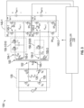
- FIG. 3 is a circuit diagram of a three-port bidirectional DC-DC converter 100 according to an exemplary embodiment.
- the exemplary embodiment shown in FIG. 3 includes a primary-side port 102 without a primary-side network 130 and secondary-side ports 104-1 and 104-2 with two different secondary-side networks 150-1 and 150-2.
- the secondary-side network 150-1 that is associated with the secondary-side port 104-1 is an LCL-T network 310 with inductors L 1 and L 2 and capacitor C
- the secondary-side network 150-2 that is associated with the secondary-side port 104-2 is an SRC network 320 with a capacitor C R and an inductor L R .
- the primary-side switches 125 (indicated as primary-side switches Q 1 -Q 4 ) and the secondary-side switches 145, including the secondary-side switches 145-1 (indicated as secondary-side switches SR (1)1 -SR (1)4 ) and secondary-side switches 145-2 (indicated as secondary-side switches SR (2)1 -SR (2)4 ), are shown.
- FIG. 3 is a three-port bidirectional DC-DC converter 100 shown with full-bridge primary-side converter 120 and secondary-side converters 140-1 and 140-2
- the discussion of FIGS. 1 and 2 should make clear that the embodiment may be modified to include additional secondary-side ports 104 and, additionally or alternately, relays that facilitate disconnection of one or more of the primary-side port 102 and secondary-side ports 104 or a dynamic change in operation of one or more of the primary-side converter 120 and secondary-side converters 140 from full-bridge mode to stacked half-bridge mode.
- the exemplary three-port bidirectional DC-DC converter 100 may operate in one of the three exemplary modes of operation noted above or other modes (e.g., secondary-side port 104-2 supplies power to primary-side port 102 and/or secondary-side port 104-1).
- the three exemplary modes are further discussed with reference to FIGS. 4-6 .
- the figures show positions of the primary-side switches 125 (Q 1 -Q 4 ), secondary-side switches 145-1 (SR (1)1 -SR (1)4 ) and secondary-side switches 145-2 (SR (2)1 -SR (2)4 ).
- the primary-side port 102 may supply power to each of the secondary-side ports 104. That is, the source voltage V IN is used to control the current I BATT1 and voltage V BATT1 outputted by the secondary-side port 104-1 and the current I BATT2 and voltage V BATT2 outputted by the secondary-side port 104-2.
- the secondary-side port 104-1 may supply power to both the primary-side port 102 and the other secondary-side port 104-2.
- the primary-side switches Q 1 -Q 4 of the primary-side converter 120 may be controlled to remain open while the secondary-side port 104-1 supplies power to the other secondary-side port 104-2.
- the values of the inductors and capacitors may be selected to facilitate fixed-frequency control of the primary-side switches Q 1 -Q 4 and secondary-side switches SR (1)1 -SR (1)4 and SR (2)1 -SR (2)4 .
- fs refers to a switching frequency of the fixed-frequency.
- Q is a predefined quality factor of the secondary-side network 150-2.
- the SRC network 320 is designed to have zero impedance at the resonant frequency of the LCL-T network 310.
- power flow is according to the LCL-T network 310, as is the case for transfer from V IN to V BATT1 in the first exemplary mode of operation.
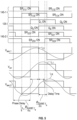
- FIG. 4 is a timeline indicating switch positions and resulting voltages during the first exemplary mode of operation of the exemplary three-port bidirectional DC-DC converter 100 of FIG. 3 .
- the primary-side port 102 may supply power to both secondary-side ports 104-1 and 104-2. This mode may be referred to as a charging mode, for example, with the primary-side port 102 supplying power that originated at the grid.
- FIG. 4 shows the position (on (closed) or off (open)) of each of the primary-side switches 125 (Q 1 -Q 4 ), secondary-side switches 145-1 (SR (1)1 -SR (1)4 ) and secondary-side switches 145-2 (SR (2)1 -SR (2)4 ) along with the currents i L1 , i L2 , and i LR through inductors L 1 , L 2 , and L R , respectively, and the voltages V pri , V sec,1 , and V sec,2 at the primary-side converter 120 and secondary-side converters 140-1 and 140-2, respectively.
- the primary-side switches 125 Q 1 -Q 4 can maintain ZVS based on power transferred to V BATT1 at the secondary-side port 104-1 without the need for frequency variation or magnetizing inductance. That is, a fixed switching frequency is possible.
- the gate pulses operating the primary-side switches 125 (Q 1 -Q 4 ) and secondary-side switches 145-1 (SR (1)1 -SR (1)4 ) are generated by using control variable ⁇ 3level .
- This control variable ⁇ 3level is the interval between turn on of switch pairs Q 1 and Q 4 , Q 2 and Q 3 , SR (1)1 and SR (1)3 , and SR (1)2 and SR (1)4 , as indicated.
- the delay between turn on of primary-side switch Q 1 and secondary-side switch SR (1)1 (and between turn on of primary-side switch Q 2 and secondary-side switch SR (1)3 ) is a controllable phase shift of T s 4 + ⁇ 3 level 4 ⁇ T s .
- the primary-side switches 125 and secondary-side switches 145-1 are subject to fixed frequency phase shift control.
- Delay Time is the interval by which turn on time for secondary-side switch SR (2)3 is delayed from the zero crossing of the current i LR that flows through the inductor L R of the SRC network 320. During this interval, the windings 105-3 get shorted, providing voltage boosting capability for the SRC network 320. Thus, the duration of the interval controls the gain of the converter at the secondary-side port 104-2. Put another way, the voltage V BATT2 at the secondary-side port 104-2 may be controlled by controlling the delay time.
- FIG. 5 is a timeline indicating switch positions and resulting voltages during the second exemplary mode of operation of the exemplary three-port bidirectional DC-DC converter 100 of FIG. 3 .
- the secondary-side port 104-1 may supply power to at least one of the primary-side port 102 and the secondary-side port 104-2.
- This mode may be referred to as a discharging mode, for example, because the voltage V BATT1 of the secondary-side port 104-1 that was previously charged may discharge in this mode to supply power to other ports.
- FIG. 5 shows the position (on (closed) or off (open)) of each of the secondary-side switches 145-1 (SR (1)1 -SR (1)4 ), primary-side switches 125 (Q 1 -Q 4 ), and secondary-side switches 145-2 (SR (2)1 -SR (2)4 ) along with the currents -iL 2 , -i L1 , and i LR through inductors L 2 , L 1 , and L R , respectively, and voltages V sec,1 , V pri , and V sec,2 at the secondary-side converter 140-1, primary-side converter 120, secondary-side converter 140-2, respectively.
- FIG. 5 shows the position (on (closed) or off (open)) of each of the secondary-side switches 145-1 (SR (1)1 -SR (1)4 ), primary-side switches 125 (Q 1 -Q 4 ), and secondary-side switches 145-2 (SR (2)1 -SR (2)4 ) along with the currents -iL 2 , -i L1 , and
- the secondary-side switches 145-1 (SR (1)1 -SR (1)4 ) are operated first and the controllable phase shift (i.e., control variable ⁇ 3level ) is applied again between switch pairs Q 1 and Q 4 , Q 2 and Q 3 , SR (1)1 and SR (1)3 , and SR (1)2 and SR (1)4 .
- the secondary-side switches 145-1 and primary-side switches 125 are subject to fixed frequency phase shift control. Further, as in the first exemplary mode discussed with reference to FIG. 4 , power of the secondary-side port 104-2 (i.e., at V BATT2 ) is still regulated using the delay time from the zero crossing of the current i LR that flows through the inductor L R of the SRC network 320 at the secondary-side port 104-2.
- FIG. 6 is a timeline indicating switch positions and resulting voltages during the third exemplary mode of operation of the exemplary three-port bidirectional DC-DC converter 100 of FIG. 3 .
- the secondary-side port 104-1 may supply power to only the secondary-side port 104-2 while the primary-side switches 125 (Q 1 -Q 4 ) are all off. This mode of operation may be used within an EV, for example.
- FIG. 6 shows the position (on (closed) or off (open)) of each of the primary-side switches 125 (Q 1 -Q 4 ) and secondary-side switches 145-1 (SR (1)1 -SR (1)4 ) and 145-2 (SR (2)1 -SR (2)4 ) along with the currents -i L2 and -i L1 through inductors L 2 and L 1 , respectively, and voltages V sec,1 and V sec,2 at the secondary-side converters 140-1 and 140-2, respectively. Because the primary-side switches 125 (Q 1 -Q 4 ) are all off, power transfer from the secondary-side port 104-1 to the secondary-side port 104-2 results in the exemplary three-port bidirectional DC-DC converter 100 of FIG.
- the secondary-side switches 145-1 and 145-2 are operated with fixed frequency phase shift control with a controllable phase shift of T s 4 + ⁇ 3 level 4 ⁇ T s .
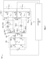
- FIG. 7 is a circuit diagram of a three-port bidirectional DC-DC converter 100 according to an exemplary embodiment.
- the exemplary embodiment shown in FIG. 7 includes a primary-side port 102 with a primary-side network 130 of a resonant inductor L aux and secondary-side ports 104-1 and 104-2 with two different secondary-side networks 150-1 and 150-2.
- the secondary-side network 150-1 that is associated with the secondary-side port 104-1 is an LCL-T network 720 with inductors L 1 and L 2 and capacitor C
- the secondary-side network 150-2 that is associated with the secondary-side port 104-2 is an energy transfer inductor L such that the exemplary secondary-side converter 140-2 is a dual active bridge (DAB) converter.
- DAB dual active bridge
- the exemplary embodiment shown in FIG. 7 is a three-port bidirectional DC-DC converter 100 shown with full-bridge primary-side converter 120 and secondary-side converters 140-1 and 140-2.
- the discussion of FIGS. 1 and 2 should make clear that the embodiment may be modified to include additional secondary-side ports 104 and, additionally or alternately, relays S 1 -S 3 , R 1,1 and R 1,2 to R 3,1 and R 3,2 , and Y 1 to Y 3 that facilitate disconnection of one or more of the primary-side port 102 and secondary-side ports 104 or a dynamic change in operation of one or more of the primary-side converter 120 and secondary-side converters 140 from full-bridge mode to stacked half-bridge mode.
- the exemplary three-port bidirectional DC-DC converter 100 may operate in one of the three exemplary modes of operation described above or other modes (e.g., secondary-side port 104-2 supplies power to primary-side port 102 and/or secondary-side port 104-1).
- the modes are further discussed with reference to FIGS. 8-10 .
- the figures show primary-side switches 125 (Q 1 -Q 4 ) and secondary-side switches 145-1 (SR (1)1 -SR (1)4 ) and 145-2 (SR (2)1 -SR (2)4 ).
- the primary-side port 102 may supply power to each of the secondary-side ports 104. That is, the source voltage V IN is used to control the current I BATT1 and voltage V BATT1 outputted by the secondary-side port 104-1 and the current I BATT2 and voltage V BATT2 outputted by the secondary-side port 104-2.
- the secondary-side port 104-1 may supply power to both the primary-side port 102 and the other secondary-side port 104-2.
- the primary-side switches Q 1 -Q 4 of the primary-side converter 120 may be controlled to remain open while the secondary-side port 104-1 supplies power to the other secondary-side port 104-2.
- the values of the inductors and capacitors may be selected to facilitate fixed frequency control of the primary-side switches Q 1 -Q 4 and secondary-side switches SR (1)1 -SR (1)4 and SR (2)1 -SR (2)4 .
- N 2 and N 3 are the number of turns for the windings 105-2 and 105-3, respectively.
- the resonant inductor L aux compensates for the fact that the energy transfer inductor L does not exhibit zero impedance at the resonant frequency of the LCL-T network 720 (unlike the SRC network 320 in FIG. 3 ).
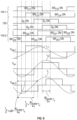
- FIG. 8 is a timeline indicating switch positions and resulting voltages during the first exemplary mode of operation of the exemplary three-port bidirectional DC-DC converter 100 of FIG. 7 .
- the primary-side port 102 may supply power to both secondary-side ports 104-1 and 104-2. This mode may be referred to as a charging mode, for example, with the primary-side port 102 supplying power originated at the grid.
- FIG. 8 shows the position (on (closed) or off (open)) of each of the primary-side switches 125 (Q 1 -Q 4 ) and secondary-side switches 145-1 (SR (1)1 -SR (1)4 ) and 145-2 (SR (2)1 -SR (2)4 ) along with the currents i L1 , i L2 , and i L through inductors L 1 , L 2 , and L, respectively, and voltages V pri , V sec,1 , and V sec,2 at the primary-side converter 120 and secondary-side converters 140-1 and 140-2, respectively.
- SR (1)1 -SR (1)4 SR (2)1 -SR (2)4
- the primary-side switches 125 (Q 1 -Q 4 ) can maintain ZVS based on power transferred to V BATT1 at the secondary-side port 104-1 without the need for frequency variation or magnetizing inductance. That is, a fixed switching frequency control is possible.
- the gate pulses operating the primary-side switches 125 (Q 1 -Q 4 ) and secondary-side switches 145-1 (SR (1)1 -SR (1)4 ) are generated by using control variable ⁇ 3level .
- This control variable ⁇ 3level is the interval between turn on of switch pairs Q 1 and Q 4 , Q 2 and Q 3 , SR (1)1 and SR (1)3 , and SR (1)2 and SR (1)4 , as indicated.
- the delay between turn on of primary-side switch Q 1 and secondary-side switch SR (1)1 (and between turn on of primary-side switch Q 2 and secondary-side switch SR (1)3 ) is a controllable phase shift of T s 4 + ⁇ 3 level 4 ⁇ T s .
- the primary-side switches 125 and secondary-side switches 145-1 are subject to fixed frequency phase shift control.
- the control variable for the DAB stage is a phase shift indicated as "Phase shift" between turn on of primary-side switch Q 1 and turn on of secondary-side switch SR (2)1 .
- the presence of the resonant inductor L aux may couple the power flow between voltages V BATT1 and V BATT2 to some extent.
- the value of the resonant inductor L aux may be kept small to minimize the coupling even though independent control of voltages V BATT1 and V BATT2 is still possible using the two different control variables, ⁇ 3level and the phase shift.
- FIG. 9 is a timeline indicating switch positions and resulting voltages during the second exemplary mode of operation of the exemplary three-port bidirectional DC-DC converter 100 of FIG. 7 .
- the secondary-side port 104-1 may supply power to the primary-side port 102 and the secondary-side port 104-2.
- This mode may be referred to as a discharging mode, for example, because the voltage V BATT1 of the primary-side port 104-1 that was previously charged may discharge in this mode.
- FIG. 9 shows the position (on (closed) or off (open)) of each of the secondary-side switches 145-1 (SR (1)1 -SR (1)4 ), primary-side switches 125 (Q 1 -Q 4 ), and secondary-side switches 145-2 (SR (2)1 -SR (2)4 ) along with the currents i L1 , i L2 , and i L through inductors L 1 , L 2 , and L, respectively, and voltages V sec,1 , V pri , and V sec,2 at the secondary-side converter 140-1, primary-side converter 120 and secondary-side converter 140-2, respectively.
- FIG. 9 shows the position (on (closed) or off (open)) of each of the secondary-side switches 145-1 (SR (1)1 -SR (1)4 ), primary-side switches 125 (Q 1 -Q 4 ), and secondary-side switches 145-2 (SR (2)1 -SR (2)4 ) along with the currents i L1 , i L2 , and i L through inductors
- the secondary-side switches 145-1 (SR (1)1 -SR (1)4 ) are operated first and the controllable phase shift (i.e., control variable ⁇ 3level ) is applied again between switch pairs Q 1 and Q 4 , Q 2 and Q 3 , SR (1)1 and SR (1)3 , and SR (1)2 and SR (1)4 .
- the secondary-side switches 145-1 and primary-side switches 125 are subject to fixed frequency phase shift control.
- the resonant inductor L aux forms one equivalent LCL-T network with the secondary-side network 150-1 and the inductor L forms another equivalent LCL-T network with secondary-side network 150-1 for the exemplary embodiment of FIG. 7 .
- ⁇ 3level is the control variable to regulate power flow from the secondary-side port 104-1 to the primary-side port 102, whereas an additional phase-shift ⁇ may be used to regulate power flow from the secondary-side port 104-1 to the secondary-side port 104-2.
- a phase shift of T s 4 + ⁇ 3 level 4 ⁇ T s is used between the secondary-side port 104-1 and the primary-side port 102, and a phase shift of T s 4 + ⁇ + ⁇ 3 level 4 ⁇ T s is used between the secondary-side port 104-1 and the secondary-side port 104-2.
- FIG. 10 is a timeline indicating switch positions and resulting voltages during the third exemplary mode of operation of the exemplary three-port bidirectional DC-DC converter 100 of FIG. 7 .
- the secondary-side port 104-1 may supply power to only the secondary-side port 104-2 while the primary-side switches 125 (Q 1 -Q 4 ) are all off. This mode of operation may be used within an EV, for example.
- FIG. 10 shows the position (on (closed) or off (open)) of each of the primary-side switches 125 (Q 1 -Q 4 ) and secondary-side switches 145-1 (SR (1)1 -SR (1)4 ) and 145-2 (SR (2)1 -SR (2)4 ) along with the currents -i L2 and - i L1 of inductors L 2 and L 1 , respectively, and voltages V sec,1 and V sec,2 at the secondary-side converters 140-1 and 140-2, respectively. Because the primary-side switches 125 (Q 1 -Q 4 ) are all off, power transfer from the secondary-side port 104-1 to the secondary-side port 104-2 results in the exemplary three-port bidirectional DC-DC converter 100 of FIG.
- the secondary-side switches 145-1 and 145-2 are operated with fixed frequency phase shift control with a controllable phase shift of T s 4 + ⁇ 3 level 4 ⁇ T s .
- FIG. 11 is a circuit diagram of a three-port bidirectional DC-DC converter 100 according to an exemplary embodiment.
- the exemplary embodiment shown in FIG. 11 is an alternate embodiment to that shown in FIG. 7 and includes a primary-side port 102 without a primary-side network 130 and secondary-side ports 104-1 and 104-2 with two different secondary-side networks 150-1 and 150-2.
- the secondary-side network 150-1 that is associated with the secondary-side port 104-1 is an LCL-T network 1110 with inductors L 1 and L 2 and capacitor C
- the secondary-side network 150-2 that is associated with the secondary-side port 104-2 is an energy transfer inductor L resulting in the secondary-side converter 140-2 being a dual active bridge (DAB) converter in the first exemplary mode of operation.
- DAB dual active bridge
- the exemplary embodiment shown in FIG. 11 includes relays S 1 -S 3 , R 1,1 , R 1,2 , R 2,1 , R 2,2 , R 3,1 , R 3,2 , and Y 1 -Y 3 , similar to those discussed with reference to FIG. 2 , that facilitate disconnection of one or more of the primary-side port 102 and secondary-side ports 104 or a dynamic change in operation of one or more of the primary-side converter 120 and secondary-side converters 140 between full-bridge mode and stacked half-bridge mode.
- the exemplary embodiment shown in FIG. 11 may be operated in one of the three exemplary modes of operation discussed above or other modes (e.g., secondary-side port 104-2 supplies power to primary-side port 102 and/or secondary-side port 104-1).
- the primary-side port 102 may supply power to each of the secondary-side ports 104. That is, the source voltage V IN is used to control the current I BATT1 and voltage V BATT1 outputted by the secondary-side port 104-1 and the current I BATT2 and voltage V BATT2 outputted by the secondary-side port 104-2.
- the secondary-side port 104-1 may supply power to both the primary-side port 102 and the other secondary-side port 104-2.
- the primary-side switches Q 1 -Q 4 of the primary-side converter 120 may be controlled to remain open while the secondary-side port 104-1 supplies power to the other secondary-side port 104-2.
- variable inductor L 1 facilitates omission of the resonant inductor L aux from the embodiment shown in FIG. 7 .
- the variable inductor L 1 may produce two discrete inductance values based on the mode of operation. During the first and second exemplary modes of operation, for example, the value of inductor L 1 may be equal to the value of inductor L 2 (according to EQ. 1) and during the third exemplary mode of operation, the value of inductor L 1 may be in accordance with EQ. 5. This allows the secondary-side converter 140-2 to be controlled as a DAB converter during power flow from secondary-side port 104-1 to secondary-side port 104-2.
- FIG. 12 is a circuit diagram of a three-port bidirectional DC-DC converter 100 according to an exemplary embodiment.
- the exemplary embodiment shown in FIG. 12 is an alternate embodiment to that shown in FIG. 7 (and FIG. 11 ) and includes a primary-side port 102 without a primary-side network 130 and secondary-side ports 104-1 and 104-2 with two different secondary-side networks 150-1 and 150-2.
- the secondary-side network 150-1 that is associated with the secondary-side port 104-1 is an LCL-T network 1210 with inductors L 1 and L 2 and capacitor C
- the secondary-side network 150-2 that is associated with the secondary-side port 104-2 is an energy transfer inductor L resulting in the secondary-side converter 140-2 being a dual active bridge (DAB) converter in the first exemplary mode of operation.
- the inductor L 2 has a variable inductance and facilitates omitting the resonant inductor L aux at the primary-side port 102 that is shown in FIG. 7 .
- the exemplary embodiment shown in FIG. 12 like the illustration in FIG. 11 , includes relays S 1 -S 3 , R 1,1 , R 1,2 , R 2,1 , R 2,2 , R 3,1 , R 3,2 , and Y 1 - Y 3 , similar to those discussed with reference to FIG. 2 , that facilitate disconnection of one or more of the primary-side port 102 and secondary-side ports 104 or a dynamic change in operation of one or more of the primary-side converter 120 and secondary-side converters 140 between full-bridge mode and stacked half-bridge mode.
- the exemplary embodiment shown in FIG. 12 may be operated in one of the three exemplary modes of operation discussed above or other modes (e.g., secondary-side port 104-2 supplies power to primary-side port 102 and/or secondary-side port 104-1).
- the primary-side port 102 may supply power to each of the secondary-side ports 104. That is, the source voltage V IN is used to control the current I BATT1 and voltage V BATT1 outputted by the secondary-side port 104-1 and the current I BATT2 and voltage V BATT2 outputted by the secondary-side port 104-2.
- the secondary-side port 104-1 may supply power to both the primary-side port 102 and the other secondary-side port 104-2.
- the primary-side switches Q 1 -Q 4 of the primary-side converter 120 may be controlled to remain open while the secondary-side port 104-1 supplies power to the other secondary-side port 104-2.
- variable inductor L 2 facilitates omission of the resonant inductor L aux from the embodiment shown in FIG. 7 .
- the variable inductor L 2 may produce two discrete inductance values based on the mode of operation.
- secondary-side converter 140-2 This allows the secondary-side converter 140-2 to be controlled equivalently as an LCL-T converter during power flow from secondary-side port 104-1 to secondary-side port 104-2.
- FIG. 13 is a circuit diagram of a three-port bidirectional DC-DC converter 100 according to an exemplary embodiment.
- the exemplary embodiment shown in FIG. 13 includes a primary-side port 102 without a primary-side network 130 and secondary-side ports 104-1 and 104-2 with the same secondary-side networks 150-1 and 150-2.
- the secondary-side networks 150-1 and 150-2 are LCL-T networks 1310 and 1320 with inductors L 1 and L 2 and capacitor C.
- L 1 the same value as L 2 , but that value is the same for both secondary-side networks 150-1 and 150-2.
- the number of turns (N 2 , N 3 ) is the same for both the secondary-side windings 105-2 and 105-3 at both secondary-side ports 104-1 and 104-2.
- the values of L 1 and L 2 in the LCL-T network 1310 need not be the same as those in the LCL-T network 1320 and the number of turns (N 2 , N 3 ) need not be the same at the secondary-side ports 104-1 and 104-2.
- the exemplary circuit of FIG. 13 is shown with relays S 1 -S 3 , R 1,1 , R 1,2 , R 2,1 , R 2,2 , R 3,1 , R 3,2 , and Y 1 to Y 3 that facilitate connection of the half-bridges in parallel or in series, as also shown in the exemplary embodiments of FIGS. 11 and 12 .
- the exemplary embodiment of FIG. 13 facilitates dynamically switching between a voltage-doubler or current-doubler mode.
- disconnection of one or more of the primary-side port 102 and secondary-side ports 104 is facilitated.
- one or more of the primary-side port 102 and secondary-side ports 104 may have full-bridge primary-side converter 120 or secondary-side converter 140, in accordance with the example shown in FIGS. 3 and 7 .
- the exemplary three-port bidirectional DC-DC converter 100 may operate in one of the three exemplary modes of operation discussed above or other modes (e.g., secondary-side port 104-2 supplies power to primary-side port 102 and/or secondary-side port 104-1).
- the three exemplary modes are further discussed with reference to FIGS. 14-16 .
- the figures show primary-side switches 125 (Q 1 -Q 4 ) and secondary-side switches 145-1 (SR (1)1 -SR (1)4 ) and 145-2 (SR (2)1 -SR (2)4 ).
- the primary-side port 102 may supply power to each of the secondary-side ports 104. That is, the source voltage V IN is used to control the current I BATT1 and voltage V BATT1 outputted by the secondary-side port 104-1 and the current I BATT2 and voltage V BATT2 outputted by the secondary-side port 104-2.
- the secondary-side port 104-1 may supply power to both the primary-side port 102 and the other secondary-side port 104-2.
- the primary-side switches Q 1 -Q 4 of the primary-side converter 120 may be controlled to remain open while the secondary-side port 104-1 supplies power to the other secondary-side port 104-2.
- FIG. 14 is a timeline indicating switch positions and resulting voltages during the first exemplary mode of operation of the exemplary three-port bidirectional DC-DC converter 100 of FIG. 13 .
- the primary-side port 102 may supply power to both secondary-side ports 104-1 and 104-2. This mode may be referred to as a charging mode, for example, with the primary-side port 102 supplying power that originated at the grid.
- FIG. 14 shows the position (on (closed) or off (open)) of each of the primary-side switches 125 (Q 1 -Q 4 ) and secondary-side switches 145-1 (SR (1)1 -SR (1)4 ) and 145-2 (SR (2)1 -SR (2)4 ) along with the currents i L1,1 + i L1,2 , i L2,1 , and i L2,2 , and the voltages V pri , V sec,1 , and V sec,2 at the primary-side converter 120 and secondary-side converters 140-1 and 140-2, respectively.
- the current i L1,1 + i L1,2 is reflected at the primary-side port 102, while each of the currents i L2,1 and i L2,2 exhibits a 90-degree shift from the primary-side voltage V pri .
- both the secondary-side networks 150-1, 150-2 being LCL-T networks 1310, 1320, independent phase shift control with fixed frequency switching is facilitated.
- a phase shift of T s 4 + ⁇ 3 level 4 ⁇ T s is used between the primary-side port 102 and the secondary-side port 104-1, while an "Additional Phase” may be used for secondary-side switches 145-2 at the secondary-side port 104-2 to independently control voltage V BATT2 .
- the voltages Vsa TT1 and V BATT2 are approximately equal.
- a non-zero value of "Additional Phase” may instead be used to control the difference between the voltages V BATT1 and V BATT2 .
- FIG. 15 is a timeline indicating switch positions and resulting voltages during the second exemplary mode of operation of the exemplary three-port bidirectional DC-DC converter 100 of FIG. 13 .
- the secondary-side port 104-1 may supply power to the primary-side port 102 and the secondary-side port 104-2.
- This mode may be referred to as a discharging mode, for example, because the voltage V BATT1 of the primary-side port 104-1 that was previously charged may discharge in this mode.
- FIG. 15 shows the position (on (closed) or off (open)) of each of the primary-side switches 125 (Q 1 -Q 4 ) and secondary-side switches 145-1 (SR (1)1 -SR (1)4 ) and 145-2 (SR (2)1 -SR (2)4 ) along with the currents -i L2,1 , -i L1,1 , and i L2,2 and the voltages V sec,1 , V pri , and V sec,2 at the secondary-side converter 140-1, primary-side converter 120, and secondary-side converter 140-2, respectively.
- the secondary-side switches 145-1 are operated first.
- the "Additional Phase" may be controlled to vary V BATT2 from V BATT1 .
- FIG. 16 is a timeline indicating switch positions and resulting voltages during the third exemplary mode of operation of the exemplary three-port bidirectional DC-DC converter 100 of FIG. 13 .
- the secondary-side port 104-1 may supply power to only the secondary-side port 104-2 while the primary-side switches 125 (Q 1 -Q 4 ) are all off. This mode of operation may be used while an EV is in drive mode, for example.
- FIG. 16 shows the position (on (closed) or off (open)) of each of the secondary-side switches 145-1 (SR (1)1 -SR (1)4 ), primary-side switches 125 (Q 1 -Q 4 ), and secondary-side switches 145-2 (SR (2)1 -SR (2)4 ) along with the currents -i L2,1 and i L2,2 , and the voltages V sec,1 and V sec,2 at the secondary-side converters 140-1 and 140-2, respectively.
- the primary-side switches 125 Q 1 -Q 4
- the current i L2,2 is phase shifted 180 degrees from the voltage V sec,1 at the secondary-side port 104-1.
- the delay from turn on of secondary-side switch S R(1)1 to turn on of secondary-side switch S R(1)3 and the delay from turn on of secondary-side switch S R(2)1 to turn on of secondary-side switch S R(2)3 is ⁇ 3 level 2 ⁇ T s and the delay between the two sets of secondary-side switches 145-1 and 145-2 is T s 2 + ⁇ 3 level 4 ⁇ T s .
- a direct current (DC)-DC converter includes a first port at a primary side of a transformer including a primary-side converter with primary-side switches, and a second port at a secondary side of the transformer.
- the second port includes a second port converter with second-port switches and a first resonant circuit including a first inductor (L 1 ), a first capacitor (C), and a second inductor (L 2 ) arranged in a "T" configuration (LCL-T).
- a third port at the secondary side of the transformer includes a third port converter with third-port switches.
- a controller controls the primary-side switches, the second-port switches, and the third-port switches at a fixed frequency for operation in a first mode, in which the first port supplies power to the second port and the third port, in a second mode, in which the second port supplies power to the first port and the third port, or in a third mode, in which the second port supplies power to the third port while the first port is disconnected.
- the controller controls the primary-side switches at the fixed frequency and to control the second-port switches and the third-port switches at the fixed frequency with a phase shift or delay from the primary-side switches.
- the controller controls the second-port switches at the fixed frequency and to control the primary-side switches and the third-port switches at the fixed frequency with a phase shift or delay from the second-port switches.
- the controller controls the primary-side switches to be open, the second-port switches at the fixed frequency, and the third-port switches at the fixed frequency with a phase shift from the second-port switches.
- the controller controls the primary-side switches, the second-port switches, and the third-port switches at the fixed frequency in additional modes of operation including modes in which the third port supplies power to the first port, to the second port, or to both the first port and the second port.
- the third port includes a third inductor (L R ) and a second capacitor (C R ) as a series resonant circuit.
- L R 1 4 ⁇ 2 fs 2 C R
- Q L R C R 8 V BATT2 ⁇ 2 I BATT2
- fs is a frequency of the fixed-frequency at which the primary-side switches, the second-port switches, and the third-port switches are controlled
- Q is a predefined quality factor
- V BATT2 is a voltage at an output of the third port
- I BATT2 is a current at the output of the third port.
- the third port includes a network with only one fourth inductor (L).
- N 1 is a number of turns of a winding at the first port and N 3 is a number of windings at the third port.
- N 2 is a number of turns of a winding at the second port, and N 3 is a number of turns of a winding at the third port.
- N 2 is a number of turns of a winding at the second port, and N 3 is a number of turns of a winding at the third port.
- the third port includes a second resonant circuit includes another first inductor (L 1 ), another first capacitor (C), and another second inductor (L 2 ) arranged in the "T" configuration (LCL-T).
- Each of the one or more additional ports includes an inductor and a capacitor as a series resonant circuit, an LCL-T resonant circuit, or a network with only one inductor.
- the first port, the second port, or the third port includes relays to dynamically change a configuration of the primary-side switches, second-port switches, or third-port switches to be half-bridges connected in series or in parallel or a full-bridge.
- a power supply includes a power factor correction (PFC) converter to convert an alternating current (AC) source to direct current (DC).
- the power supply also includes a DC-DC converter coupled to the PFC.
- the DC-DC converter includes a first port at a primary side of a transformer including a primary-side converter with primary-side switches, and a second port at a secondary side of the transformer.
- the second port includes a second port converter with second-port switches and a first resonant circuit including a first inductor (L 1 ), a first capacitor (C), and a second inductor (L 2 ) arranged in a "T" configuration (LCL-T).
- the DC-DC converter also includes a third port at the secondary side of the transformer.
- the third port includes a third port converter with third-port switches.
- a controller controls the primary-side switches, the second-port switches, and the third-port switches at a fixed frequency for operation in a first mode, in which the first port supplies power to the second port and the third port, in a second mode, in which the second port supplies power to the first port and the third port, or in a third mode, in which the second port supplies power to the third port while the first port is disconnected.
- the controller controls the primary-side switches at the fixed frequency and controls the second-port switches and the third-port switches at the fixed frequency with a phase shift or delay from the primary-side switches.
- the controller controls the second-port switches at the fixed frequency and controls the primary-side switches and the third-port switches at the fixed frequency with a phase shift or delay from the second-port switches.
- the controller controls the primary-side switches to be open, the second-port switches at the fixed frequency, and the third-port switches at the fixed frequency with a phase shift from the second-port switches.
- the DC-DC converter includes one or more additional ports at the secondary side of the transformer.
- Each of the one or more additional ports includes additional port switches and an inductor and a capacitor as a series resonant circuit, an LCL-T resonant circuit, or a network with only one inductor.
- the controller controls the primary-side switches, the second-port switches, the third-port switches, and the additional port switches at the fixed frequency in additional modes of operation including modes in which the third port supplies power to the first port, to the second port, or to both the first port and the second port.
- the third port includes an inductor (L R ) and a capacitor (C R ) as a series resonant circuit, the third port includes a network with only one inductor (L), or the third port includes a second resonant circuit including another first inductor (L 1 ), another first capacitor (C), and another second inductor (L 2 ) arranged in the "T" configuration (LCL-T).
- the first port, the second port, or the third port includes relays to dynamically change a configuration of the primary-side switches, second-port switches, or third-port switches to be half-bridges connected in series or in parallel or a full-bridge.
- a method of assembling a direct current (DC)-DC converter includes assembling a first port at a primary side of a transformer to include a primary-side converter with primary-side switches, and assembling a second port at a secondary side of the transformer to include a second port converter with second-port switches and a resonant circuit including a first inductor (L 1 ), a capacitor (C), and a second inductor (L 2 ) arranged in a "T" configuration (LCL-T).
- the method also includes assembling a third port at the secondary side of the transformer to include a third port converter with third-port switches.
- a controller controls the primary-side switches, the second-port switches, and the third-port switches at fixed-frequency for operation in a first mode, in which the first port supplies power to the second port and the third port, in a second mode, in which the second port supplies power to the first port and the third port, or in a third mode, in which the second port supplies power to the third port while the first port is disconnected.
Landscapes
- Engineering & Computer Science (AREA)
- Power Engineering (AREA)
- Dc-Dc Converters (AREA)
Abstract
Description
- This invention relates to direct current (DC)-to-DC conversion and, more particularly, to a multiple-port bidirectional DC-DC converter with fixed switching frequency operation.
- In many applications, a DC-DC converter is used to adjust a source DC voltage to the level needed by a particular load. The source DC voltage may be obtained by rectifying an alternative current (AC) source (e.g., grid) as part of a power supply that has the DC-DC converter as the last stage, following a power factor correction (PFC) converter, for example. Generally, a DC-DC converter may include a DC-AC converter that converts the source DC to AC, a transformer that passes the AC signal by electromagnetic induction to a secondary side of the transformer, and an AC-DC converter on the secondary side to provide the voltage level needed at the output. A multiple-port DC-DC converter allows a single DC source to supply power to more than one port at the secondary side of the transformer, with each of those ports connected to a different load. For redundancy and reliability, it may be desirable to have bidirectional operation, which refers to a port that is typically a store of energy being able to act as a source, instead.
- According to one or more embodiments, a direct current (DC)-DC converter includes a first port at a primary side of a transformer including a primary-side converter with primary-side switches, and a second port at a secondary side of the transformer. The second port includes a second port converter with second-port switches and a resonant circuit including a first inductor (L1), a capacitor (C), and a second inductor (L2) arranged in a "T" configuration (LCL-T). A third port at the secondary side of the transformer includes a third port converter with third-port switches. A controller controls the primary-side switches, the second-port switches, and the third-port switches at fixed-frequency for operation in a first mode, in which the first port supplies power to the second port and the third port, in a second mode, in which the second port supplies power to the first port and the third port, or in a third mode, in which the second port supplies power to the third port while the first port is disconnected.
- According to another embodiment, a power supply includes a power factor correction (PFC) converter to convert an alternating current (AC) source to direct current (DC) and a DC-DC converter coupled to the PFC. The DC-DC converter includes a first port at a primary side of a transformer including a primary-side converter with primary-side switches, and a second port at a secondary side of the transformer. The second port includes a second port converter with second-port switches and a resonant circuit including a first inductor (L1), a capacitor (C), and a second inductor (L2) arranged in a "T" configuration (LCL-T). A third port at the secondary side of the transformer includes a third port converter with third-port switches. A controller controls the primary-side switches, the second-port switches, and the third-port switches at fixed-frequency for operation in a first mode, in which the first port supplies power to the second port and the third port, in a second mode, in which the second port supplies power to the first port and the third port, or in a third mode, in which the second port supplies power to the third port while the first port is disconnected.
- According to another embodiment, a method of assembling a direct current (DC)-DC converter includes assembling a first port at a primary side of a transformer to include a primary-side converter with primary-side switches, and assembling a second port at a secondary side of the transformer to include a second port converter with second-port switches and a resonant circuit including a first inductor (L1), a capacitor (C), and a second inductor (L2) arranged in a "T" configuration (LCL-T). The method also includes assembling a third port at the secondary side of the transformer to include a third port converter with third-port switches. The method further includes configuring a controller to control the primary-side switches, the second-port switches, and the third-port switches at fixed-frequency for operation in a first mode, in which the first port supplies power to the second port and the third port, in a second mode, in which the second port supplies power to the first port and the third port, or in a third mode, in which the second port supplies power to the third port while the first port is disconnected.
- The foregoing has outlined some of the pertinent features of the disclosed subject matter. These features are merely illustrative.
- The examples described throughout the present document will be better understood with reference to the following drawings and descriptions. In the figures, like-referenced numerals designate corresponding parts throughout the different views.
-
FIG. 1 is a circuit diagram of a generalized multiple-port bidirectional direct current (DC)-DC converter according to exemplary embodiments; -
FIG. 2 is a circuit diagram of a generalized dynamically configurable multiple-port bidirectional DC-DC converter according to exemplary embodiments; -
FIG. 3 is a circuit diagram of a three-port bidirectional DC-DC converter according to an exemplary embodiment; -
FIG. 4 is a timeline indicating switch positions and resulting voltages during a first exemplary mode of operation of the exemplary three-port bidirectional DC-DC converter ofFIG. 3 ; -
FIG. 5 is a timeline indicating switch positions and resulting voltages during a second exemplary mode of operation of the exemplary three-port bidirectional DC-DC converter ofFIG. 3 ; -
FIG. 6 is a timeline indicating switch positions and resulting voltages during a third exemplary mode of operation of the exemplary three-port bidirectional DC-DC converter ofFIG. 3 ; -
FIG. 7 is a circuit diagram of a three-port bidirectional DC-DC converter according to an exemplary embodiment; -
FIG. 8 is a timeline indicating switch positions and resulting voltages during a first exemplary mode of operation of the exemplary three-port bidirectional DC-DC converter ofFIG. 7 ; -
FIG. 9 is a timeline indicating switch positions and resulting voltages during a second exemplary mode of operation of the exemplary three-port bidirectional DC-DC converter ofFIG. 7 ; -
FIG. 10 is a timeline indicating switch positions and resulting voltages during a third exemplary mode of operation of the exemplary three-port bidirectional DC-DC converter ofFIG. 7 ; -
FIG. 11 is a circuit diagram of an alternate embodiment of the three-port bidirectional DC-DC converter ofFIG. 7 ; -
FIG. 12 is a circuit diagram of an alternate embodiment of the three-port bidirectional DC-DC converter ofFIG. 7 ; -
FIG. 13 is a circuit diagram of a three-port bidirectional DC-DC converter according to an exemplary embodiment; -
FIG. 14 is a timeline indicating switch positions and resulting voltages during a first exemplary mode of operation of the exemplary three-port bidirectional DC-DC converter ofFIG. 13 ; -
FIG. 15 is a timeline indicating switch positions and resulting voltages during a second exemplary mode of operation of the exemplary three-port bidirectional DC-DC converter ofFIG. 13 ; and -
FIG. 16 is a timeline indicating switch positions and resulting voltages during a third exemplary mode of operation of the exemplary three-port bidirectional DC-DC converter ofFIG. 13 . - Reference will now be made to the drawings to describe the present disclosure in detail. It will be understood that the drawings and exemplified embodiments are not limited to the details thereof. Modifications may be made without departing from the spirit and scope of the disclosed subject matter.
- As previously noted, a DC-DC converter may be implemented as a multiple-port bidirectional DC-DC converter. Multiple port refers to three or more ports with a source port on a primary side of a transformer and two or more ports on a secondary side of the transformer. In this case, a single DC source is converted at the two or more ports. Bidirectional refers to the transfer of power in both directions within the DC-DC converter, such that one or more of the ports (on the secondary side) that is typically supplied with energy may instead act as a source according to exemplary modes of operation.
- The bidirectional configuration provides redundancy and increases reliability. Such reliability may be helpful for DC micro-grids, charging stations, and electric vehicles (EVs), among other applications. For example, in an EV, a multiple-port DC-DC converter may be used to supply loads associated with convenience features (e.g., infotainment system) as well as loads associated with comfort features (e.g., heating system). A bidirectional arrangement facilitates power transfer among the ports, on the secondary side of the transformer, that supply the loads, as well as to the source, as needed.
- Generally, each port of the DC-DC converter includes a full or half-bridge converter circuit and may include an impedance or resonant circuit. In terms of bidirectional power flow, a prior approach involves using an inductor-capacitor-inductor (LCL) resonant circuit in a T configuration (LCL-T) at a secondary-side port. The LCL-T resonant circuit facilitates controlling switches of the converter circuits at fixed-frequency, rather than at variable-frequency, with a phase shift between control of the switches on the primary and secondary sides. However, this configuration can be problematic in some cases (e.g., for low-voltage loads), because the additional components of the LCL-T resonant circuit increase losses.
- Another prior approach involves using a series resonant converter (SRC), which includes a capacitor and inductor in series with the transformer. In a configuration involving SRC, output voltage can be regulated with secondary-side switch control. That is, a time delay may be introduced in the secondary-side switching pulses with respect to the primary-side switching pulses. Typically, SRC with secondary-side switch control requires variable switching frequency control to maintain zero voltage switching (ZVS) turn-on of the switches. Also, at light load operation, with variable switching frequency control, the switching frequency may become so high that the switches lose ZVS. However, if the switches are operated with a fixed switching frequency, the switches cannot achieve ZVS turn on. In this case, in order to achieve ZVS, the magnetizing inductance of the transformer would need to be decreased.
- Yet another prior approach involves a dual-active bridge (DAB) converter at a secondary port side. DAB converters are operated with fixed switching frequency and a phase shift between the switches of the primary-side converter and the secondary-side converter. However, at light loads, the stored energy in the inductor of DAB converters may be insufficiently small and may result in loss of ZVS.
- In some situations, a multiple-port bidirectional DC-DC converter with fixed switching frequency operation is appreciated. Such a converter may simplify the design of magnetic components and also simplify the control. Embodiments detailed herein relate to multiple-port bidirectional DC-DC converters with a LCL-T resonant circuit at least at one port and an SRC or DAB converter or another LCL-T resonant circuit at least at another port on the secondary side. This results in fixed frequency control of the switches of the converters and also allows achieving ZVS even at lighter loads without the need to operate at very high switching frequencies. As detailed, numerous embodiments facilitate identifying the optimized configuration based on the application (e.g., DC micro-grid, charging station, EV) and expected loads.
-
FIG. 1 is a circuit diagram of a multiple-port bidirectional DC-DC converter 100 according to exemplary embodiments. The exemplary generalized multi-port bidirectional DC-DC converter 100 shown inFIG. 1 has a primary-side port 102 on a primary side of atransformer 103 and n secondary-side ports 104-1 through 104-n (generally referred to as secondary-side port 104) at a secondary side of thetransformer 103 for a total of n+1 ports. Thus, thetransformer 103 is an (n+1)-winding transformer with windings 105-1 through 105-(n+1) (generally referred to as winding 105), each with a number of turns N1 through Nn+1. A controller 110 is coupled to each of the primary-side port 102 and secondary-side ports 104 for controlling the switches of the multiple-port bidirectional DC-DC converter 100, as further discussed. - The exemplary multi-port bidirectional DC-
DC converter 100 is shown inFIG. 1 as being part of apower supply 10. As shown, thepower supply 10 is a two-stage supply with a power factor correction (PFC)converter 14 as a first stage and the multiple-port bidirectional DC-DC converter 100 as the second stage. ThePFC converter 14 performs power factor correction and rectifies agrid AC 12 in the exemplary case. ThePFC converter 14 provides a DC output, which may be used as the source voltage VIN at the primary side of the multiple-port bidirectional DC-DC converter 100. - A first exemplary mode of operation of the multiple-port bidirectional DC-
DC converter 100 may involve the source voltage VIN on the primary side supplying power to one or more of the n secondary-side ports 104 on the secondary side of thetransformer 103 via inductive coupling. The source voltage VIN may be obtained via power factor correction of a grid voltage as part of a charging station, for example. A primary-side converter 120 may convert the source voltage VIN to AC, based on control of the primary-side switches 125 of the primary-side converter 120, to facilitate the inductive coupling via thetransformer 103. - On the secondary side, at two or more secondary-
side ports 104, secondary-side converters 140-1 through 140-n (generally referred to as secondary-side converter 140) may respectively convert the inductively coupled AC to DC currents IBATT1 through IBATTn, resulting, respectively, in voltages VBATT1 through VBATTn that are provided to loads coupled to the secondary-side ports 104. The secondary-side converters 140-1 through 140-n include sets of secondary-side switches 145-1 through 145-n (generally referred to as secondary-side switches 145) respectively. In the exemplary multiple-port bidirectional DC-DC converter 100 shown inFIG. 1 , the secondary-side switches 145-1 are labelled SR(1)1 through SR(1)4 and the secondary-side switches 145-n are labelled SR(n)1 through SR(n)4. The primary-side converter 120 and secondary-side converters 140 are shown as full-bridge switching circuits in the exemplary embodiment illustrated inFIG. 1 . - A second exemplary mode of operation of the multiple-port bidirectional DC-
DC converter 100 may involve a power source (e.g., VBATT1) of one of the secondary-side ports (e.g., 104-1) supplying the primary-side port 102, as well as one or more other secondary-side ports (104-2 through 104-n). A third exemplary mode of operation of the multiple-port bidirectional DC-DC converter 100 may involve a power source (e.g., VBATT1) of one of the secondary-side ports (e.g., 104-1) supplying only one or more other secondary-side ports (104-2 through 104-n), with the primary-side port 102 disconnected (i.e., with all the primary-side switches 125 open). - Each of these exemplary modes and the control of the primary-
side switches 125 and secondary-side switches 145 used to implement the modes is detailed for different embodiments of the multiple-port bidirectional DC-DC converter 100. However, the examples are not intended to limit all the modes of operation that are possible for the multiple-port bidirectional DC-DC converter 100 according to the various embodiments. In general, in addition to the primary-side port 102, any secondary-side port 104 may supply power to one or more of the primary-side port 102 and the other secondary-side ports 104. - As indicated, the primary-
side port 102 may include a primary-side network 130 and the secondary-side ports 104-1 through 104-n may respectively include secondary-side networks 150-1 through 150-n (generally referred to as secondary-side network 150). Blocking capacitor CB1 on the primary side and blocking capacitor CB2 at the secondary-side port 104-1 on the secondary side prevent saturation of thetransformer 103 by blocking any DC excitation from the inverter (i.e., primary-side converter 120) and/or rectifier (i.e., secondary-side converter 140-1). -
FIG. 2 is a circuit diagram of a dynamically configurable multiple-port bidirectional DC-DC converter 100 according to exemplary embodiments. Like the exemplary embodiment shown inFIG. 1 , the exemplary multiple-port bidirectional DC-DC converter 100 ofFIG. 2 also includes a primary-side port 102 and n secondary-side ports 104 with an (n+1)-windingtransformer 103. In addition, the primary-side port 102 may have a respective primary-side network 130 between the winding and primary-side converter 120, and each secondary-side port 104 may have a respective secondary-side network 150 between the winding and secondary-side converter 140, as indicated for the illustrated primary-side port 102 and secondary-side ports 104-1, 104-2, and 104-n. - However, while the embodiment shown in
FIG. 1 illustrates full bridge operation of the secondary-side converters 140, the exemplary embodiment shown inFIG. 2 facilitates dynamic operation in various modes and configurations. For example, the circuit diagram shown inFIG. 2 facilitates disconnection of any of the primary-side port 102 and secondary-side ports 104. Specifically, the relay Sk associated with a given winding 105-k may be opened to disconnect the corresponding primary-side port 102 or secondary-side port 104. For example, opening the relay S1 would disconnect the primary-side port 102, while opening the relay S2 would disconnect the secondary-side port 104-1. Default operation may involve all the primary-side port 102 and secondary-side ports 104 being enabled and, thus, all the relays S1 through Sn+1 being closed. Operation in the third exemplary mode of operation may involve opening relays of all the primary-side port 102 and secondary-side ports 104 except those of secondary-side ports 104-1 and 104-n so that the secondary-side port 104-1 supplies power to only the secondary-side port 104-n, for example. - In addition to facilitating the dynamic disconnection of a primary-
side port 102 or secondary-side port 104 via a relay Sk, the configuration shown inFIG. 2 facilitates dynamic operation in full or half-bridge mode at any of the primary-side port 102 and secondary-side ports 104 based on additional relays. For a given primary-side port 102 or secondary-side port 104 associated with winding 105-k, operation of the primary-side converter 120 or secondary-side converter 140 in full-bridge mode is facilitated by the relays Rk,1 and Rk,2 being closed while the relay Yk is open. For example, the secondary-side converter 140 at the secondary-side port 104-2 may be operated in full-bridge mode by closing relays R3,1 and R3,2 and opening relay Y3. Similarly, closing relays R1,1 and R1,2 and opening relay Y1 would result in the primary-side converter 120 operating in full-bridge mode. - Complementary setting of the relays would result in stacked half-bridge operation. That is, opening the relays Rk,1 and Rk,2 while closing the relay Yk would result in the corresponding primary-
side converter 120 or secondary-side converter 140 operating in stacked half-bridge mode. As indicated thecontroller 110 may control the relays in addition to the converter switches. -
FIG. 3 is a circuit diagram of a three-port bidirectional DC-DC converter 100 according to an exemplary embodiment. The exemplary embodiment shown inFIG. 3 includes a primary-side port 102 without a primary-side network 130 and secondary-side ports 104-1 and 104-2 with two different secondary-side networks 150-1 and 150-2. Specifically, the secondary-side network 150-1 that is associated with the secondary-side port 104-1 is an LCL-T network 310 with inductors L1 and L2 and capacitor C, and the secondary-side network 150-2 that is associated with the secondary-side port 104-2 is anSRC network 320 with a capacitor CR and an inductor LR. The primary-side switches 125 (indicated as primary-side switches Q1-Q4) and the secondary-side switches 145, including the secondary-side switches 145-1 (indicated as secondary-side switches SR(1)1-SR(1)4) and secondary-side switches 145-2 (indicated as secondary-side switches SR(2)1-SR(2)4), are shown. - While the exemplary embodiment shown in
FIG. 3 is a three-port bidirectional DC-DC converter 100 shown with full-bridge primary-side converter 120 and secondary-side converters 140-1 and 140-2, the discussion ofFIGS. 1 and2 should make clear that the embodiment may be modified to include additional secondary-side ports 104 and, additionally or alternately, relays that facilitate disconnection of one or more of the primary-side port 102 and secondary-side ports 104 or a dynamic change in operation of one or more of the primary-side converter 120 and secondary-side converters 140 from full-bridge mode to stacked half-bridge mode. - As previously noted, the exemplary three-port bidirectional DC-
DC converter 100 may operate in one of the three exemplary modes of operation noted above or other modes (e.g., secondary-side port 104-2 supplies power to primary-side port 102 and/or secondary-side port 104-1). The three exemplary modes are further discussed with reference toFIGS. 4-6 . The figures show positions of the primary-side switches 125 (Q1-Q4), secondary-side switches 145-1 (SR(1)1-SR(1)4) and secondary-side switches 145-2 (SR(2)1-SR(2)4). They also show the currents iL1, iL2, and iLR through inductors L1, L2, and LR, respectively, and voltages Vpri, Vsec,1, and Vsec,2 at the primary-side converter 120 and secondary-side converters 140-1 and 140-2, respectively. - In the first exemplary mode of operation, the primary-
side port 102 may supply power to each of the secondary-side ports 104. That is, the source voltage VIN is used to control the current IBATT1 and voltage VBATT1 outputted by the secondary-side port 104-1 and the current IBATT2 and voltage VBATT2 outputted by the secondary-side port 104-2. In the second exemplary mode of operation, the secondary-side port 104-1 may supply power to both the primary-side port 102 and the other secondary-side port 104-2. In the third exemplary mode of operation, the primary-side switches Q1-Q4 of the primary-side converter 120 may be controlled to remain open while the secondary-side port 104-1 supplies power to the other secondary-side port 104-2. - The values of the inductors and capacitors may be selected to facilitate fixed-frequency control of the primary-side switches Q1-Q4 and secondary-side switches SR(1)1-SR(1)4 and SR(2)1-SR(2)4. For the LCL-
T network 310, the values are given by:

- In EQ. 2, fs refers to a switching frequency of the fixed-frequency. For the
SRC network 320, the values are given by:

- In EQ. 4, Q is a predefined quality factor of the secondary-side network 150-2. The
SRC network 320 is designed to have zero impedance at the resonant frequency of the LCL-T network 310. Thus, during operation in the third exemplary mode of operation, power flow is according to the LCL-T network 310, as is the case for transfer from VIN to VBATT1 in the first exemplary mode of operation. -
FIG. 4 is a timeline indicating switch positions and resulting voltages during the first exemplary mode of operation of the exemplary three-port bidirectional DC-DC converter 100 ofFIG. 3 . As previously noted, in the first exemplary mode of operation, the primary-side port 102 may supply power to both secondary-side ports 104-1 and 104-2. This mode may be referred to as a charging mode, for example, with the primary-side port 102 supplying power that originated at the grid. -
FIG. 4 shows the position (on (closed) or off (open)) of each of the primary-side switches 125 (Q1-Q4), secondary-side switches 145-1 (SR(1)1-SR(1)4) and secondary-side switches 145-2 (SR(2)1-SR(2)4) along with the currents iL1, iL2, and iLR through inductors L1, L2, and LR, respectively, and the voltages Vpri, Vsec,1, and Vsec,2 at the primary-side converter 120 and secondary-side converters 140-1 and 140-2, respectively. Based on the secondary-side network 150-1 being the LCL-T network 310, the primary-side switches 125 Q1-Q4 can maintain ZVS based on power transferred to VBATT1 at the secondary-side port 104-1 without the need for frequency variation or magnetizing inductance. That is, a fixed switching frequency is possible. - The gate pulses operating the primary-side switches 125 (Q1-Q4) and secondary-side switches 145-1 (SR(1)1-SR(1)4) are generated by using control variable Ø3level. This control variable Ø3level is the interval between turn on of switch pairs Q1 and Q4, Q2 and Q3, SR(1)1 and SR(1)3, and SR(1)2 and SR(1)4, as indicated. As indicated in
FIG. 4 , the delay between turn on of primary-side switch Q1 and secondary-side switch SR(1)1 (and between turn on of primary-side switch Q2 and secondary-side switch SR(1)3) is a controllable phase shift of
side port 102 and the secondary-side port 104-1, the primary-side switches 125 and secondary-side switches 145-1 are subject to fixed frequency phase shift control. - At the secondary port 104-2, which has a secondary-side network 150-2 that is an
SRC network 320, a variable delay time, indicated as "Delay Time," is used to generate the gate pulses operating the secondary-side switches 145-2 (SR(2)1-SR(2)4). Delay time is the interval by which turn on time for secondary-side switch SR(2)3 is delayed from the zero crossing of the current iLR that flows through the inductor LR of theSRC network 320. During this interval, the windings 105-3 get shorted, providing voltage boosting capability for theSRC network 320. Thus, the duration of the interval controls the gain of the converter at the secondary-side port 104-2. Put another way, the voltage VBATT2 at the secondary-side port 104-2 may be controlled by controlling the delay time. -
FIG. 5 is a timeline indicating switch positions and resulting voltages during the second exemplary mode of operation of the exemplary three-port bidirectional DC-DC converter 100 ofFIG. 3 . As previously noted, in the second exemplary mode of operation, the secondary-side port 104-1 may supply power to at least one of the primary-side port 102 and the secondary-side port 104-2. This mode may be referred to as a discharging mode, for example, because the voltage VBATT1 of the secondary-side port 104-1 that was previously charged may discharge in this mode to supply power to other ports. -
FIG. 5 shows the position (on (closed) or off (open)) of each of the secondary-side switches 145-1 (SR(1)1-SR(1)4), primary-side switches 125 (Q1-Q4), and secondary-side switches 145-2 (SR(2)1-SR(2)4) along with the currents -iL2, -iL1, and iLR through inductors L2, L1, and LR, respectively, and voltages Vsec,1, Vpri, and Vsec,2 at the secondary-side converter 140-1, primary-side converter 120, secondary-side converter 140-2, respectively. AsFIG. 5 indicates, the secondary-side switches 145-1 (SR(1)1-SR(1)4) are operated first and the controllable phase shift (i.e., control variable Ø3level) is applied again between switch pairs Q1 and Q4, Q2 and Q3, SR(1)1 and SR(1)3, and SR(1)2 and SR(1)4. - That is, between the secondary-side port 104-1 and the primary-
side port 102, the secondary-side switches 145-1 and primary-side switches 125 are subject to fixed frequency phase shift control. Further, as in the first exemplary mode discussed with reference toFIG. 4 , power of the secondary-side port 104-2 (i.e., at VBATT2) is still regulated using the delay time from the zero crossing of the current iLR that flows through the inductor LR of theSRC network 320 at the secondary-side port 104-2. -
FIG. 6 is a timeline indicating switch positions and resulting voltages during the third exemplary mode of operation of the exemplary three-port bidirectional DC-DC converter 100 ofFIG. 3 . As previously noted, in the third exemplary mode of operation, the secondary-side port 104-1 may supply power to only the secondary-side port 104-2 while the primary-side switches 125 (Q1-Q4) are all off. This mode of operation may be used within an EV, for example. -
FIG. 6 shows the position (on (closed) or off (open)) of each of the primary-side switches 125 (Q1-Q4) and secondary-side switches 145-1 (SR(1)1-SR(1)4) and 145-2 (SR(2)1-SR(2)4) along with the currents -iL2 and -iL1 through inductors L2 and L1, respectively, and voltages Vsec,1 and Vsec,2 at the secondary-side converters 140-1 and 140-2, respectively. Because the primary-side switches 125 (Q1-Q4) are all off, power transfer from the secondary-side port 104-1 to the secondary-side port 104-2 results in the exemplary three-port bidirectional DC-DC converter 100 ofFIG. 3 behaving like an LCL-T resonant converter. Thus, asFIG. 6 indicates, the secondary-side switches 145-1 and 145-2 are operated with fixed frequency phase shift control with a controllable phase shift of
- In a different exemplary mode of operation, in which the secondary-side port 104-2 supplies power to only the secondary-side port 104-1, the operation of the secondary-side switches 145-1 and 145-2 shown in
FIG. 6 would be interchanged. That is, operation of secondary-side switches 145-2 would lead the operation of secondary-side switches 145-1. However, the same fixed switching frequency would be employed with a controllable phase shift of
-
FIG. 7 is a circuit diagram of a three-port bidirectional DC-DC converter 100 according to an exemplary embodiment. The exemplary embodiment shown inFIG. 7 includes a primary-side port 102 with a primary-side network 130 of a resonant inductor Laux and secondary-side ports 104-1 and 104-2 with two different secondary-side networks 150-1 and 150-2. Specifically, the secondary-side network 150-1 that is associated with the secondary-side port 104-1 is an LCL-T network 720 with inductors L1 and L2 and capacitor C, and the secondary-side network 150-2 that is associated with the secondary-side port 104-2 is an energy transfer inductor L such that the exemplary secondary-side converter 140-2 is a dual active bridge (DAB) converter. - Like the exemplary embodiment shown in
FIG. 3 , the exemplary embodiment shown inFIG. 7 is a three-port bidirectional DC-DC converter 100 shown with full-bridge primary-side converter 120 and secondary-side converters 140-1 and 140-2. However, the discussion ofFIGS. 1 and2 should make clear that the embodiment may be modified to include additional secondary-side ports 104 and, additionally or alternately, relays S1-S3, R1,1 and R1,2 to R3,1 and R3,2, and Y1 to Y3 that facilitate disconnection of one or more of the primary-side port 102 and secondary-side ports 104 or a dynamic change in operation of one or more of the primary-side converter 120 and secondary-side converters 140 from full-bridge mode to stacked half-bridge mode. - As previously noted, the exemplary three-port bidirectional DC-
DC converter 100 may operate in one of the three exemplary modes of operation described above or other modes (e.g., secondary-side port 104-2 supplies power to primary-side port 102 and/or secondary-side port 104-1). The modes are further discussed with reference toFIGS. 8-10 . The figures show primary-side switches 125 (Q1-Q4) and secondary-side switches 145-1 (SR(1)1-SR(1)4) and 145-2 (SR(2)1-SR(2)4). They also show the currents iL1, iL2, and iL through inductors L1, L2, and L, respectively, and voltages Vpri, Vsec,1, and Vsec,2 at the primary-side converter 120 and secondary-side converters 140-1 and 140-2, respectively. - In the first exemplary mode of operation, the primary-
side port 102 may supply power to each of the secondary-side ports 104. That is, the source voltage VIN is used to control the current IBATT1 and voltage VBATT1 outputted by the secondary-side port 104-1 and the current IBATT2 and voltage VBATT2 outputted by the secondary-side port 104-2. In the second exemplary mode of operation, the secondary-side port 104-1 may supply power to both the primary-side port 102 and the other secondary-side port 104-2. In the third exemplary mode of operation, the primary-side switches Q1-Q4 of the primary-side converter 120 may be controlled to remain open while the secondary-side port 104-1 supplies power to the other secondary-side port 104-2. - The values of the inductors and capacitors may be selected to facilitate fixed frequency control of the primary-side switches Q1-Q4 and secondary-side switches SR(1)1-SR(1)4 and SR(2)1-SR(2)4. The values are given by:



- As previously noted, N2 and N3 are the number of turns for the windings 105-2 and 105-3, respectively. The resonant inductor Laux compensates for the fact that the energy transfer inductor L does not exhibit zero impedance at the resonant frequency of the LCL-T network 720 (unlike the
SRC network 320 inFIG. 3 ). -
FIG. 8 is a timeline indicating switch positions and resulting voltages during the first exemplary mode of operation of the exemplary three-port bidirectional DC-DC converter 100 ofFIG. 7 . As previously noted, in the first exemplary mode of operation, the primary-side port 102 may supply power to both secondary-side ports 104-1 and 104-2. This mode may be referred to as a charging mode, for example, with the primary-side port 102 supplying power originated at the grid. -
FIG. 8 shows the position (on (closed) or off (open)) of each of the primary-side switches 125 (Q1-Q4) and secondary-side switches 145-1 (SR(1)1-SR(1)4) and 145-2 (SR(2)1-SR(2)4) along with the currents iL1, iL2, and iL through inductors L1, L2, and L, respectively, and voltages Vpri, Vsec,1, and Vsec,2 at the primary-side converter 120 and secondary-side converters 140-1 and 140-2, respectively. As noted with reference toFIG. 4 , based on the secondary-side network 150-1 being the LCL-T network 720, the primary-side switches 125 (Q1-Q4) can maintain ZVS based on power transferred to VBATT1 at the secondary-side port 104-1 without the need for frequency variation or magnetizing inductance. That is, a fixed switching frequency control is possible. - The gate pulses operating the primary-side switches 125 (Q1-Q4) and secondary-side switches 145-1 (SR(1)1-SR(1)4) are generated by using control variable Ø3level. This control variable Ø3level is the interval between turn on of switch pairs Q1 and Q4, Q2 and Q3, SR(1)1 and SR(1)3, and SR(1)2 and SR(1)4, as indicated. As indicated in
FIG. 8 , the delay between turn on of primary-side switch Q1 and secondary-side switch SR(1)1 (and between turn on of primary-side switch Q2 and secondary-side switch SR(1)3) is a controllable phase shift of
side port 102 and the secondary-side port 104-1, the primary-side switches 125 and secondary-side switches 145-1 are subject to fixed frequency phase shift control. - At the secondary port 104-2, which has a secondary-side network 150-2 that includes the energy transfer inductor L, the control variable for the DAB stage is a phase shift indicated as "Phase shift" between turn on of primary-side switch Q1 and turn on of secondary-side switch SR(2)1. The presence of the resonant inductor Laux may couple the power flow between voltages VBATT1 and VBATT2 to some extent. The value of the resonant inductor Laux may be kept small to minimize the coupling even though independent control of voltages VBATT1 and VBATT2 is still possible using the two different control variables, Ø3level and the phase shift.
-
FIG. 9 is a timeline indicating switch positions and resulting voltages during the second exemplary mode of operation of the exemplary three-port bidirectional DC-DC converter 100 ofFIG. 7 . As previously noted, in the second exemplary mode of operation, the secondary-side port 104-1 may supply power to the primary-side port 102 and the secondary-side port 104-2. This mode may be referred to as a discharging mode, for example, because the voltage VBATT1 of the primary-side port 104-1 that was previously charged may discharge in this mode. -
FIG. 9 shows the position (on (closed) or off (open)) of each of the secondary-side switches 145-1 (SR(1)1-SR(1)4), primary-side switches 125 (Q1-Q4), and secondary-side switches 145-2 (SR(2)1-SR(2)4) along with the currents iL1, iL2, and iL through inductors L1, L2, and L, respectively, and voltages Vsec,1, Vpri, and Vsec,2 at the secondary-side converter 140-1, primary-side converter 120 and secondary-side converter 140-2, respectively. AsFIG. 9 indicates, the secondary-side switches 145-1 (SR(1)1-SR(1)4) are operated first and the controllable phase shift (i.e., control variable Ø3level) is applied again between switch pairs Q1 and Q4, Q2 and Q3, SR(1)1 and SR(1)3, and SR(1)2 and SR(1)4. - That is, between the secondary-side port 104-1 and the primary-
side port 102, the secondary-side switches 145-1 and primary-side switches 125 are subject to fixed frequency phase shift control. Unlike during operation in the second exemplary mode, discussed with reference toFIG. 5 , the resonant inductor Laux forms one equivalent LCL-T network with the secondary-side network 150-1 and the inductor L forms another equivalent LCL-T network with secondary-side network 150-1 for the exemplary embodiment ofFIG. 7 . That is, Ø3level is the control variable to regulate power flow from the secondary-side port 104-1 to the primary-side port 102, whereas an additional phase-shift ΔØ may be used to regulate power flow from the secondary-side port 104-1 to the secondary-side port 104-2. Specifically, as shown, a phase shift of
side port 102, and a phase shift of
-
FIG. 10 is a timeline indicating switch positions and resulting voltages during the third exemplary mode of operation of the exemplary three-port bidirectional DC-DC converter 100 ofFIG. 7 . As previously noted, in the third exemplary mode of operation, the secondary-side port 104-1 may supply power to only the secondary-side port 104-2 while the primary-side switches 125 (Q1-Q4) are all off. This mode of operation may be used within an EV, for example. -
FIG. 10 shows the position (on (closed) or off (open)) of each of the primary-side switches 125 (Q1-Q4) and secondary-side switches 145-1 (SR(1)1-SR(1)4) and 145-2 (SR(2)1-SR(2)4) along with the currents -iL2 and - iL1 of inductors L2 and L1, respectively, and voltages Vsec,1 and Vsec,2 at the secondary-side converters 140-1 and 140-2, respectively. Because the primary-side switches 125 (Q1-Q4) are all off, power transfer from the secondary-side port 104-1 to the secondary-side port 104-2 results in the exemplary three-port bidirectional DC-DC converter 100 ofFIG. 7 behaving like an LCL-T resonant converter. Thus, asFIG. 10 indicates, the secondary-side switches 145-1 and 145-2 are operated with fixed frequency phase shift control with a controllable phase shift of
-
FIG. 11 is a circuit diagram of a three-port bidirectional DC-DC converter 100 according to an exemplary embodiment. The exemplary embodiment shown inFIG. 11 is an alternate embodiment to that shown inFIG. 7 and includes a primary-side port 102 without a primary-side network 130 and secondary-side ports 104-1 and 104-2 with two different secondary-side networks 150-1 and 150-2. The secondary-side network 150-1 that is associated with the secondary-side port 104-1 is an LCL-T network 1110 with inductors L1 and L2 and capacitor C, and the secondary-side network 150-2 that is associated with the secondary-side port 104-2 is an energy transfer inductor L resulting in the secondary-side converter 140-2 being a dual active bridge (DAB) converter in the first exemplary mode of operation. The inductor L1 has a variable inductance and facilitates omitting the resonant inductor Laux at the primary-side port 102 that is shown inFIG. 7 . - Unlike the exemplary embodiments shown in
FIGS. 3 and7 , which are shown with full-bridge primary-side converter 120 and secondary-side converters 140-1 and 140-2, the exemplary embodiment shown inFIG. 11 includes relays S1-S3, R1,1, R1,2, R2,1, R2,2, R3,1, R3,2, and Y1-Y3, similar to those discussed with reference toFIG. 2 , that facilitate disconnection of one or more of the primary-side port 102 and secondary-side ports 104 or a dynamic change in operation of one or more of the primary-side converter 120 and secondary-side converters 140 between full-bridge mode and stacked half-bridge mode. - As discussed with reference to
FIG. 7 , the exemplary embodiment shown inFIG. 11 may be operated in one of the three exemplary modes of operation discussed above or other modes (e.g., secondary-side port 104-2 supplies power to primary-side port 102 and/or secondary-side port 104-1). In the first exemplary mode of operation, the primary-side port 102 may supply power to each of the secondary-side ports 104. That is, the source voltage VIN is used to control the current IBATT1 and voltage VBATT1 outputted by the secondary-side port 104-1 and the current IBATT2 and voltage VBATT2 outputted by the secondary-side port 104-2. In the second exemplary mode of operation, the secondary-side port 104-1 may supply power to both the primary-side port 102 and the other secondary-side port 104-2. In the third exemplary mode of operation, the primary-side switches Q1-Q4 of the primary-side converter 120 may be controlled to remain open while the secondary-side port 104-1 supplies power to the other secondary-side port 104-2. - As noted, the variable inductor L1 facilitates omission of the resonant inductor Laux from the embodiment shown in
FIG. 7 . The variable inductor L1 may produce two discrete inductance values based on the mode of operation. During the first and second exemplary modes of operation, for example, the value of inductor L1 may be equal to the value of inductor L2 (according to EQ. 1) and during the third exemplary mode of operation, the value of inductor L1 may be in accordance with EQ. 5. This allows the secondary-side converter 140-2 to be controlled as a DAB converter during power flow from secondary-side port 104-1 to secondary-side port 104-2. -
FIG. 12 is a circuit diagram of a three-port bidirectional DC-DC converter 100 according to an exemplary embodiment. The exemplary embodiment shown inFIG. 12 is an alternate embodiment to that shown inFIG. 7 (andFIG. 11 ) and includes a primary-side port 102 without a primary-side network 130 and secondary-side ports 104-1 and 104-2 with two different secondary-side networks 150-1 and 150-2. The secondary-side network 150-1 that is associated with the secondary-side port 104-1 is an LCL-T network 1210 with inductors L1 and L2 and capacitor C, and the secondary-side network 150-2 that is associated with the secondary-side port 104-2 is an energy transfer inductor L resulting in the secondary-side converter 140-2 being a dual active bridge (DAB) converter in the first exemplary mode of operation. The inductor L2 has a variable inductance and facilitates omitting the resonant inductor Laux at the primary-side port 102 that is shown inFIG. 7 . - Unlike the exemplary embodiments shown in
FIGS. 3 and7 , which are shown with full-bridge primary-side converter 120 and secondary-side converters 140-1 and 140-2, the exemplary embodiment shown inFIG. 12 , like the illustration inFIG. 11 , includes relays S1-S3, R1,1, R1,2, R2,1, R2,2, R3,1, R3,2, and Y1- Y3, similar to those discussed with reference toFIG. 2 , that facilitate disconnection of one or more of the primary-side port 102 and secondary-side ports 104 or a dynamic change in operation of one or more of the primary-side converter 120 and secondary-side converters 140 between full-bridge mode and stacked half-bridge mode. - As discussed with reference to
FIG. 7 , the exemplary embodiment shown inFIG. 12 may be operated in one of the three exemplary modes of operation discussed above or other modes (e.g., secondary-side port 104-2 supplies power to primary-side port 102 and/or secondary-side port 104-1). In the first exemplary mode of operation, the primary-side port 102 may supply power to each of the secondary-side ports 104. That is, the source voltage VIN is used to control the current IBATT1 and voltage VBATT1 outputted by the secondary-side port 104-1 and the current IBATT2 and voltage VBATT2 outputted by the secondary-side port 104-2. In the second exemplary mode of operation, the secondary-side port 104-1 may supply power to both the primary-side port 102 and the other secondary-side port 104-2. In the third exemplary mode of operation, the primary-side switches Q1-Q4 of the primary-side converter 120 may be controlled to remain open while the secondary-side port 104-1 supplies power to the other secondary-side port 104-2. - As noted, the variable inductor L2 facilitates omission of the resonant inductor Laux from the embodiment shown in
FIG. 7 . The variable inductor L2 may produce two discrete inductance values based on the mode of operation. During the first and second exemplary modes of operation, the value of inductor L1 may be equal to the value of inductor L2 (according to EQ. 1) and the fixed switching frequency may be in accordance with EQ. 6 or:
- During the first and second exemplary modes of operation, power is transferred from primary-
side port 102 and secondary-side port 104-1, respectively, to secondary-side port 104-2 with DAB operation. During the third exemplary mode of operation, the value of inductor L2 may be in accordance with EQ. 5 and the fixed switching frequency may be given by:
- This allows the secondary-side converter 140-2 to be controlled equivalently as an LCL-T converter during power flow from secondary-side port 104-1 to secondary-side port 104-2.
-
FIG. 13 is a circuit diagram of a three-port bidirectional DC-DC converter 100 according to an exemplary embodiment. The exemplary embodiment shown inFIG. 13 includes a primary-side port 102 without a primary-side network 130 and secondary-side ports 104-1 and 104-2 with the same secondary-side networks 150-1 and 150-2. Specifically, the secondary-side networks 150-1 and 150-2 are LCL-T networks - In the exemplary embodiment of
FIG. 13 , not only is L1 the same value as L2, but that value is the same for both secondary-side networks 150-1 and 150-2. In addition, the number of turns (N2, N3) is the same for both the secondary-side windings 105-2 and 105-3 at both secondary-side ports 104-1 and 104-2. However, in alternate embodiments, the values of L1 and L2 in the LCL-T network 1310 need not be the same as those in the LCL-T network 1320 and the number of turns (N2, N3) need not be the same at the secondary-side ports 104-1 and 104-2. - The exemplary circuit of
FIG. 13 is shown with relays S1-S3, R1,1, R1,2, R2,1, R2,2, R3,1, R3,2, and Y1 to Y3 that facilitate connection of the half-bridges in parallel or in series, as also shown in the exemplary embodiments ofFIGS. 11 and12 . Thus, the exemplary embodiment ofFIG. 13 facilitates dynamically switching between a voltage-doubler or current-doubler mode. In addition, disconnection of one or more of the primary-side port 102 and secondary-side ports 104 is facilitated. However, in alternate embodiments, one or more of the primary-side port 102 and secondary-side ports 104 may have full-bridge primary-side converter 120 or secondary-side converter 140, in accordance with the example shown inFIGS. 3 and7 . - As previously noted, the exemplary three-port bidirectional DC-
DC converter 100 may operate in one of the three exemplary modes of operation discussed above or other modes (e.g., secondary-side port 104-2 supplies power to primary-side port 102 and/or secondary-side port 104-1). The three exemplary modes are further discussed with reference toFIGS. 14-16 . The figures show primary-side switches 125 (Q1-Q4) and secondary-side switches 145-1 (SR(1)1-SR(1)4) and 145-2 (SR(2)1-SR(2)4). They also show the currents iL1,1 and IL2,1, through the inductors L1 and L2, respectively, of the LCL-T network 1310 and iL1,2 and iL2,2, through the inductors L1 and L2, respectively, of the LCL-T network 1320, as well as voltages Vpri, Vsec,1, and Vsec,2 at the primary-side converter 120 and secondary-side converters 140-1 and 140-2, respectively. - In the first exemplary mode of operation, the primary-
side port 102 may supply power to each of the secondary-side ports 104. That is, the source voltage VIN is used to control the current IBATT1 and voltage VBATT1 outputted by the secondary-side port 104-1 and the current IBATT2 and voltage VBATT2 outputted by the secondary-side port 104-2. In the second exemplary mode of operation, the secondary-side port 104-1 may supply power to both the primary-side port 102 and the other secondary-side port 104-2. In the third exemplary mode of operation, the primary-side switches Q1-Q4 of the primary-side converter 120 may be controlled to remain open while the secondary-side port 104-1 supplies power to the other secondary-side port 104-2. -
FIG. 14 is a timeline indicating switch positions and resulting voltages during the first exemplary mode of operation of the exemplary three-port bidirectional DC-DC converter 100 ofFIG. 13 . As previously noted, in the first exemplary mode of operation, the primary-side port 102 may supply power to both secondary-side ports 104-1 and 104-2. This mode may be referred to as a charging mode, for example, with the primary-side port 102 supplying power that originated at the grid. -
FIG. 14 shows the position (on (closed) or off (open)) of each of the primary-side switches 125 (Q1-Q4) and secondary-side switches 145-1 (SR(1)1-SR(1)4) and 145-2 (SR(2)1-SR(2)4) along with the currents iL1,1 + iL1,2, iL2,1, and iL2,2, and the voltages Vpri, Vsec,1, and Vsec,2 at the primary-side converter 120 and secondary-side converters 140-1 and 140-2, respectively. The current iL1,1 + iL1,2 is reflected at the primary-side port 102, while each of the currents iL2,1 and iL2,2 exhibits a 90-degree shift from the primary-side voltage V pri . Based on both the secondary-side networks 150-1, 150-2 being LCL-T networks - That is, as shown, a phase shift of

side port 102 and the secondary-side port 104-1, while an "Additional Phase" may be used for secondary-side switches 145-2 at the secondary-side port 104-2 to independently control voltage VBATT2. When the "Additional Phase" is zero for the exemplary circuit ofFIG. 13 , the voltages VsaTT1 and VBATT2 are approximately equal. A non-zero value of "Additional Phase" may instead be used to control the difference between the voltages VBATT1 and VBATT2. -
FIG. 15 is a timeline indicating switch positions and resulting voltages during the second exemplary mode of operation of the exemplary three-port bidirectional DC-DC converter 100 ofFIG. 13 . As previously noted, in the second exemplary mode of operation, the secondary-side port 104-1 may supply power to the primary-side port 102 and the secondary-side port 104-2. This mode may be referred to as a discharging mode, for example, because the voltage VBATT1 of the primary-side port 104-1 that was previously charged may discharge in this mode. -
FIG. 15 shows the position (on (closed) or off (open)) of each of the primary-side switches 125 (Q1-Q4) and secondary-side switches 145-1 (SR(1)1-SR(1)4) and 145-2 (SR(2)1-SR(2)4) along with the currents -iL2,1, -iL1,1, and iL2,2 and the voltages Vsec,1, Vpri, and Vsec,2 at the secondary-side converter 140-1, primary-side converter 120, and secondary-side converter 140-2, respectively. AsFIG. 15 indicates, the secondary-side switches 145-1 (SR(1)1-SR(1)4) are operated first. AsFIG. 15 also shows, the current -iL1,1 is shifted 90 degrees from the voltage Vsec,1 at the secondary-side port 104-1, but the current iL2,2 is shifted 180 degrees from the voltage Vsec,1. As noted with reference toFIG. 14 , the "Additional Phase" may be controlled to vary VBATT2 from VBATT1. -
FIG. 16 is a timeline indicating switch positions and resulting voltages during the third exemplary mode of operation of the exemplary three-port bidirectional DC-DC converter 100 ofFIG. 13 . As previously noted, in the third exemplary mode of operation, the secondary-side port 104-1 may supply power to only the secondary-side port 104-2 while the primary-side switches 125 (Q1-Q4) are all off. This mode of operation may be used while an EV is in drive mode, for example. -
FIG. 16 shows the position (on (closed) or off (open)) of each of the secondary-side switches 145-1 (SR(1)1-SR(1)4), primary-side switches 125 (Q1-Q4), and secondary-side switches 145-2 (SR(2)1-SR(2)4) along with the currents -iL2,1 and iL2,2, and the voltages Vsec,1 and Vsec,2 at the secondary-side converters 140-1 and 140-2, respectively. As indicated, the primary-side switches 125 (Q1-Q4) are all off. The current iL2,2 is phase shifted 180 degrees from the voltage Vsec,1 at the secondary-side port 104-1. The delay from turn on of secondary-side switch SR(1)1 to turn on of secondary-side switch SR(1)3 and the delay from turn on of secondary-side switch SR(2)1 to turn on of secondary-side switch SR(2)3 is
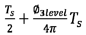
- According to the various aspects and embodiments detailed herein:
A direct current (DC)-DC converter includes a first port at a primary side of a transformer including a primary-side converter with primary-side switches, and a second port at a secondary side of the transformer. The second port includes a second port converter with second-port switches and a first resonant circuit including a first inductor (L1), a first capacitor (C), and a second inductor (L2) arranged in a "T" configuration (LCL-T). A third port at the secondary side of the transformer includes a third port converter with third-port switches. A controller controls the primary-side switches, the second-port switches, and the third-port switches at a fixed frequency for operation in a first mode, in which the first port supplies power to the second port and the third port, in a second mode, in which the second port supplies power to the first port and the third port, or in a third mode, in which the second port supplies power to the third port while the first port is disconnected. - In the first mode, the controller controls the primary-side switches at the fixed frequency and to control the second-port switches and the third-port switches at the fixed frequency with a phase shift or delay from the primary-side switches.
- In the second mode, the controller controls the second-port switches at the fixed frequency and to control the primary-side switches and the third-port switches at the fixed frequency with a phase shift or delay from the second-port switches.
- In the third mode, the controller controls the primary-side switches to be open, the second-port switches at the fixed frequency, and the third-port switches at the fixed frequency with a phase shift from the second-port switches.
- The controller controls the primary-side switches, the second-port switches, and the third-port switches at the fixed frequency in additional modes of operation including modes in which the third port supplies power to the first port, to the second port, or to both the first port and the second port.
- The third port includes a third inductor (LR) and a second capacitor (CR) as a series resonant circuit. In this case,


fs is a frequency of the fixed-frequency at which the primary-side switches, the second-port switches, and the third-port switches are controlled, Q is a predefined quality factor, VBATT2 is a voltage at an output of the third port, and IBATT2 is a current at the output of the third port. - The third port includes a network with only one fourth inductor (L). In this case,


fs is a frequency of the fixed frequency at which the primary-side switches, the second-port switches, and the third-port switches are controlled, N2 is a number of turns of a winding at the second port, and N3 is a number of turns of a winding at the third port. - The first port further includes an auxiliary inductor (Laux), and
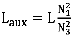
- The first inductor (L1) is a variable inductor and L1 = L2 -


- The third port includes a second resonant circuit includes another first inductor (L1), another first capacitor (C), and another second inductor (L2) arranged in the "T" configuration (LCL-T).
- There are one or more additional ports at the secondary side of the transformer. Each of the one or more additional ports includes an inductor and a capacitor as a series resonant circuit, an LCL-T resonant circuit, or a network with only one inductor.
- The first port, the second port, or the third port includes relays to dynamically change a configuration of the primary-side switches, second-port switches, or third-port switches to be half-bridges connected in series or in parallel or a full-bridge.
- A power supply includes a power factor correction (PFC) converter to convert an alternating current (AC) source to direct current (DC). The power supply also includes a DC-DC converter coupled to the PFC. The DC-DC converter includes a first port at a primary side of a transformer including a primary-side converter with primary-side switches, and a second port at a secondary side of the transformer. The second port includes a second port converter with second-port switches and a first resonant circuit including a first inductor (L1), a first capacitor (C), and a second inductor (L2) arranged in a "T" configuration (LCL-T). The DC-DC converter also includes a third port at the secondary side of the transformer. The third port includes a third port converter with third-port switches. A controller controls the primary-side switches, the second-port switches, and the third-port switches at a fixed frequency for operation in a first mode, in which the first port supplies power to the second port and the third port, in a second mode, in which the second port supplies power to the first port and the third port, or in a third mode, in which the second port supplies power to the third port while the first port is disconnected.
- In the first mode, the controller controls the primary-side switches at the fixed frequency and controls the second-port switches and the third-port switches at the fixed frequency with a phase shift or delay from the primary-side switches. In the second mode, the controller controls the second-port switches at the fixed frequency and controls the primary-side switches and the third-port switches at the fixed frequency with a phase shift or delay from the second-port switches. In the third mode, the controller controls the primary-side switches to be open, the second-port switches at the fixed frequency, and the third-port switches at the fixed frequency with a phase shift from the second-port switches.
- The DC-DC converter includes one or more additional ports at the secondary side of the transformer. Each of the one or more additional ports includes additional port switches and an inductor and a capacitor as a series resonant circuit, an LCL-T resonant circuit, or a network with only one inductor. The controller controls the primary-side switches, the second-port switches, the third-port switches, and the additional port switches at the fixed frequency in additional modes of operation including modes in which the third port supplies power to the first port, to the second port, or to both the first port and the second port.
- The third port includes an inductor (LR) and a capacitor (CR) as a series resonant circuit, the third port includes a network with only one inductor (L), or the third port includes a second resonant circuit including another first inductor (L1), another first capacitor (C), and another second inductor (L2) arranged in the "T" configuration (LCL-T).
- The first port, the second port, or the third port includes relays to dynamically change a configuration of the primary-side switches, second-port switches, or third-port switches to be half-bridges connected in series or in parallel or a full-bridge.
- A method of assembling a direct current (DC)-DC converter includes assembling a first port at a primary side of a transformer to include a primary-side converter with primary-side switches, and assembling a second port at a secondary side of the transformer to include a second port converter with second-port switches and a resonant circuit including a first inductor (L1), a capacitor (C), and a second inductor (L2) arranged in a "T" configuration (LCL-T). The method also includes assembling a third port at the secondary side of the transformer to include a third port converter with third-port switches. A controller controls the primary-side switches, the second-port switches, and the third-port switches at fixed-frequency for operation in a first mode, in which the first port supplies power to the second port and the third port, in a second mode, in which the second port supplies power to the first port and the third port, or in a third mode, in which the second port supplies power to the third port while the first port is disconnected.
Claims (15)
- A direct current (DC)-DC converter (100), characterized by comprising:a first port (102) at a primary side of a transformer (103) comprising a primary-side converter (120) with primary-side switches (125);a second port (104-1) at a secondary side of the transformer (103), the second port (104-1) comprising a second port converter (140-1) with second-port switches (145-1) and a first resonant circuit (310) comprising a first inductor (L1), a first capacitor (C), and a second inductor (L2) arranged in a "T" configuration;a third port (104-2) at the secondary side of the transformer (103), the third port (104-2) comprising a third port converter (140-2) with third-port switches (145-2); anda controller (110) configured to control the primary-side switches (125), the second-port switches (145-1), and the third-port switches (145-2) at fixed-frequency for operation in a first mode, in which the first port (102) supplies power to the second port (104-1) and the third port (104-2), in a second mode, in which the second port (104-1) supplies power to the first port (102) and the third port (104-2), or in a third mode, in which the second port (104-1) supplies power to the third port (104-2) while the first port (102) is disconnected.
- The DC-DC converter (100) according to claim 1, wherein, in the first mode, the controller (110) is configured to control the primary-side switches (125) at fixed-frequency and to control the second-port switches (145-1) and the third-port switches (145-2) at fixed-frequency with a phase shift or delay from the primary-side switches (125),
wherein, in the second mode, the controller (110) is configured to control the second-port switches (145-1) at fixed-frequency and to control the primary-side switches (125) and the third-port switches (145-2) at fixed-frequency with a phase shift or delay from the second-port switches (145-1). - The DC-DC converter (100) according to claim 1, wherein, in the third mode, the controller (110) is configured to control the primary-side switches (125) to be open, the second-port switches (145-1) at fixed-frequency, and the third-port switches (145-2) at fixed-frequency with a phase shift from the second-port switches (145-1).
- The DC-DC converter (100) according to claim 1, wherein the controller (110) is further configured to control the primary-side switches (125), the second-port switches (145-1), and the third-port switches (145-2) at fixed-frequency in additional modes of operation comprising modes in which the third port (104-2) supplies power to the first port (102), to the second port (104-1), or to both the first port (102) and the second port (104-1).
- The DC-DC converter (100) according to claim 1, wherein the third port (104-2) comprises a third inductor (LR) and a second capacitor (CR) as a series resonant circuit (320).
- The DC-DC converter according to claim 5, wherein


L1, L2, C, LR, and CR are the first inductor, the second inductor, the first capacitor, the third inductor, and the second capacitor respectively, fs is a frequency of the fixed-frequency at which the primary-side switches (125), the second-port switches (145-1), and the third-port switches (145-2) are controlled, Q is a predefined quality factor, VBATT2 is a voltage at an output of the third port (104-2), and IBATT2 is a current at the output of the third port (104-2). - The DC-DC converter (100) according to claim 1, wherein the third port (104-2 - FIG. 7) comprises a network with only one fourth inductor (L).
- The DC-DC converter (100) according to claim 7, wherein


L1, L2, L, and C are the first inductor, the second inductor, the fourth inductor, and the first capacitor respectively, fs is a frequency of the fixed-frequency at which the primary-side switches (125), the second-port switches (145-1), and the third-port switches (145-2) are controlled, N2 is a number of turns of a winding at the second port (104-1), and N3 is a number of turns of a winding at the third port (104-2). - The DC-DC converter (100) according to claim 7, wherein the first port (102) further comprises an auxiliary inductor (Laux), and

Laux is the auxiliary inductor, L is the fourth inductor, N1 is a number of turns of a winding at the first port (102), and N3 is a number of turns of a winding at the third port (104-2). - The DC-DC converter (100) according to claim 7, wherein the first inductor (L1) is a variable inductor and

L1, L2, and L are the first inductor, the second inductor, and the fourth inductor respectively, N2 is a number of turns of a winding at the second port (104-1), and N3 is a number of turns of a winding at the third port (104-2), or the second inductor (L2) is a variable inductor and
L1, L2, and L are the first inductor, the second inductor, and the fourth inductor respectively, N2 is a number of turns of a winding at the second port (104-1), and N3 is a number of turns of a winding at the third port (104-2). - The DC-DC converter (100) according to claim 1, wherein the third port (104-2 - FIG. 13) comprises a second resonant circuit (1320) comprising another first inductor (L1), another first capacitor (C), and another second inductor (L2) arranged in the "T" configuration.
- The DC-DC converter (100) according to claim 1, further comprising one or more additional ports at the secondary side of the transformer (103), wherein each of the one or more additional ports comprises an inductor and a capacitor as a series resonant circuit, an LCL-T resonant circuit, or a network with only one inductor.
- The DC-DC converter (100) according to claim 1, wherein the first port (102), the second port (104-1), or the third port (104-2) comprises relays (R1,1, R1,2, R2,1, R2,2, R3,1, R3,2) to dynamically change a configuration of the primary-side switches (125), the second-port switches (145-1), or the third-port switches (145-2) to be half-bridges connected in series or in parallel or a full-bridge.
- The DC-DC converter (100) according to any of claims 1-13, wherein the DC-DC converter (100) is adapted to be coupled to a power factor correction converter (14) to form a power supply (10), and the power factor correction converter (14) is configured to converter an alternating current source (12) to direct current (VIN).
- A method of assembling a direct current (DC)-DC converter (100), the method characterized by comprising:assembling a first port (102) at a primary side of a transformer (103) to include a primary-side converter (120) with primary-side switches (125);assembling a second port (104-1) at a secondary side of the transformer (103) to include a second port converter (140-1) with second-port switches (145-1) and a resonant circuit (310) comprising a first inductor (L1), a capacitor (C), and a second inductor (L2) arranged in a "T" configuration;assembling a third port (104-2) at the secondary side of the transformer (103) to include a third port converter (140-2) with third-port switches (145-2); andconfiguring a controller (110) to control the primary-side switches (125), the second-port switches (145-1), and the third-port switches (145-2) at fixed-frequency for operation in a first mode, in which the first port (102) supplies power to the second port (104-1) and the third port (104-2), in a second mode, in which the second port (104-1) supplies power to the first port (102) and the third port (104-2), or in a third mode, in which the second port (104-1) supplies power to the third port (104-2) while the first port (102) is disconnected.
Applications Claiming Priority (1)
| Application Number | Priority Date | Filing Date | Title |
|---|---|---|---|
| US18/330,205 US12592647B2 (en) | 2023-06-06 | 2023-06-06 | Multiple-port bidirectional DC-DC converters and control methods therof |
Publications (1)
| Publication Number | Publication Date |
|---|---|
| EP4475419A1 true EP4475419A1 (en) | 2024-12-11 |
Family
ID=91376642
Family Applications (1)
| Application Number | Title | Priority Date | Filing Date |
|---|---|---|---|
| EP24179842.0A Pending EP4475419A1 (en) | 2023-06-06 | 2024-06-04 | Dc-dc converter, power supply and method of assembling dc-dc converter |
Country Status (3)
| Country | Link |
|---|---|
| US (1) | US12592647B2 (en) |
| EP (1) | EP4475419A1 (en) |
| CN (1) | CN119093740A (en) |
Families Citing this family (1)
| Publication number | Priority date | Publication date | Assignee | Title |
|---|---|---|---|---|
| US20240223097A1 (en) * | 2022-12-23 | 2024-07-04 | Mcmaster University | Dual-active bridge converter and applications of same |
Citations (3)
| Publication number | Priority date | Publication date | Assignee | Title |
|---|---|---|---|---|
| US20220045618A1 (en) * | 2020-08-04 | 2022-02-10 | Delta Electronics, Inc. | Multiple-port bidirectional converter and control method thereof |
| US20220321016A1 (en) * | 2021-03-29 | 2022-10-06 | University Of Maryland, College Park | Multi-port power converters and power conversion systems, and methods for design and operation thereof |
| US20230155514A1 (en) * | 2021-10-28 | 2023-05-18 | Utah State University | Constant current to constant voltage dual active bridge lcl-t resonant dc-dc converter |
Family Cites Families (11)
| Publication number | Priority date | Publication date | Assignee | Title |
|---|---|---|---|---|
| US5430633A (en) * | 1993-09-14 | 1995-07-04 | Astec International, Ltd. | Multi-resonant clamped flyback converter |
| US20100135045A1 (en) * | 2008-10-15 | 2010-06-03 | Hitoshi Inoue | Sine Wave Inverter |
| US8619438B2 (en) * | 2011-05-19 | 2013-12-31 | Infineon Technologies Ag | Resonant converter |
| US9931951B2 (en) | 2014-06-13 | 2018-04-03 | University Of Maryland | Integrated dual-output grid-to-vehicle (G2V) and vehicle-to-grid (V2G) onboard charger for plug-in electric vehicles |
| JP6097270B2 (en) * | 2014-12-10 | 2017-03-15 | 株式会社豊田中央研究所 | Power conversion circuit system |
| DE112016001372T8 (en) | 2015-03-25 | 2018-01-11 | Sunpower Corporation | Converter topologies for common mode voltage reduction |
| CN109703399B (en) | 2018-12-27 | 2021-05-18 | 台达电子企业管理(上海)有限公司 | Vehicle-mounted charging and discharging system and control method applicable to same |
| WO2020096655A1 (en) | 2019-06-26 | 2020-05-14 | Huawei Technologies Co., Ltd. | Bidirectional multiple-port power conversion system and method |
| TWI766314B (en) | 2020-07-21 | 2022-06-01 | 茂達電子股份有限公司 | Power converter with automatic balance mechanism of flying capacitor |
| CN115995985B (en) | 2023-02-13 | 2025-06-17 | 重庆邮电大学 | A control method for a bidirectional symmetrical LLC resonant converter |
| EP4641906A4 (en) * | 2023-04-25 | 2026-04-29 | Samsung Electronics Co Ltd | LLC RESONANCE TRANSDUCER AND ELECTRONIC DEVICE WITH IT |
-
2023
- 2023-06-06 US US18/330,205 patent/US12592647B2/en active Active
-
2024
- 2024-06-04 EP EP24179842.0A patent/EP4475419A1/en active Pending
- 2024-06-05 CN CN202410722860.XA patent/CN119093740A/en active Pending
Patent Citations (3)
| Publication number | Priority date | Publication date | Assignee | Title |
|---|---|---|---|---|
| US20220045618A1 (en) * | 2020-08-04 | 2022-02-10 | Delta Electronics, Inc. | Multiple-port bidirectional converter and control method thereof |
| US20220321016A1 (en) * | 2021-03-29 | 2022-10-06 | University Of Maryland, College Park | Multi-port power converters and power conversion systems, and methods for design and operation thereof |
| US20230155514A1 (en) * | 2021-10-28 | 2023-05-18 | Utah State University | Constant current to constant voltage dual active bridge lcl-t resonant dc-dc converter |
Non-Patent Citations (3)
| Title |
|---|
| KUMAR MISHA ET AL: "Isolated Three-Port Bidirectional DC-DC Converter for Electric Vehicle Applications", 2022 IEEE APPLIED POWER ELECTRONICS CONFERENCE AND EXPOSITION (APEC), IEEE, 20 March 2022 (2022-03-20), pages 2000 - 2007, XP034124750, DOI: 10.1109/APEC43599.2022.9773690 * |
| MUKHERJEE SATYAKI ET AL: "A High Power Density Wide Range DC-DC Converter for Universal Electric Vehicle Charging", IEEE TRANSACTIONS ON POWER ELECTRONICS, INSTITUTE OF ELECTRICAL AND ELECTRONICS ENGINEERS, USA, vol. 38, no. 2, 24 October 2022 (2022-10-24), pages 1998 - 2012, XP011927443, ISSN: 0885-8993, [retrieved on 20221115], DOI: 10.1109/TPEL.2022.3217092 * |
| TWINAME ROSS P ET AL: "A New Resonant Bidirectional DC-DC Converter Topo", IEEE TRANSACTIONS ON POWER ELECTRONICS, INSTITUTE OF ELECTRICAL AND ELECTRONICS ENGINEERS, USA, vol. 29, no. 9, 1 September 2014 (2014-09-01), pages 4733 - 4740, XP011546720, ISSN: 0885-8993, [retrieved on 20140430], DOI: 10.1109/TPEL.2013.2288325 * |
Also Published As
| Publication number | Publication date |
|---|---|
| CN119093740A (en) | 2024-12-06 |
| US20240413760A1 (en) | 2024-12-12 |
| US12592647B2 (en) | 2026-03-31 |
Similar Documents
| Publication | Publication Date | Title |
|---|---|---|
| US6310785B1 (en) | Zero voltage switching DC-DC converter | |
| US11777411B2 (en) | Resonant power converter for wide voltage switching | |
| EP3952092A1 (en) | Multiple-port bidirectional converter and control method thereof | |
| US11021069B1 (en) | Multisource magnetic integration using a current source fed transformer structure with decoupled secondary windings | |
| EP1126593A2 (en) | Controller for power supply and method of operation thereof | |
| Lee et al. | A two-stage isolated/bidirectional DC/DC converter with current ripple reduction technique | |
| US20120032509A1 (en) | Voltage transforming device and method and power supply system | |
| US12451815B2 (en) | Voltage transformer | |
| US20240235245A9 (en) | Three-phase and single-phase two-way charger | |
| CN102668719B (en) | Device for controlling a plurality of electrical consumers | |
| US12592647B2 (en) | Multiple-port bidirectional DC-DC converters and control methods therof | |
| EP4730370A1 (en) | Magnetic integrated transformer and onboard three-port converter | |
| US11632052B2 (en) | Dual active bridge with distributed inductance | |
| US5936857A (en) | Power converter having multiple output voltage capability | |
| US20220337165A1 (en) | High voltage converter with switch modules parallel driving a single transformer primary | |
| US20240128008A1 (en) | Transformer of an electrical system for dc voltage conversion and for charging of batteries of a vehicle | |
| US20240258801A1 (en) | Charging and balancing batteries | |
| KR101548528B1 (en) | DC/DC converter | |
| Hoffmann et al. | Multiwinding based semi-dual active bridge converter | |
| KR102307484B1 (en) | Low Voltage Isolation DC/DC Converter for Electric Vehicles | |
| US12438469B2 (en) | Switched-mode power supply having coupled step-down converter stages | |
| Hoffmann et al. | Isolated multiport converter as cost efficient solution for dc-fast charger of electric vehicle | |
| US12362664B2 (en) | Series resonant power converter | |
| US11736024B1 (en) | Current balancing in coupled transformers | |
| KR102705539B1 (en) | Interleaved Converters Using The Secondary LLC Resonant Circuit, And Power Converting Apparatus Using The Same |
Legal Events
| Date | Code | Title | Description |
|---|---|---|---|
| PUAI | Public reference made under article 153(3) epc to a published international application that has entered the european phase |
Free format text: ORIGINAL CODE: 0009012 |
|
| STAA | Information on the status of an ep patent application or granted ep patent |
Free format text: STATUS: THE APPLICATION HAS BEEN PUBLISHED |
|
| AK | Designated contracting states |
Kind code of ref document: A1 Designated state(s): AL AT BE BG CH CY CZ DE DK EE ES FI FR GB GR HR HU IE IS IT LI LT LU LV MC ME MK MT NL NO PL PT RO RS SE SI SK SM TR |
|
| STAA | Information on the status of an ep patent application or granted ep patent |
Free format text: STATUS: REQUEST FOR EXAMINATION WAS MADE |
|
| 17P | Request for examination filed |
Effective date: 20250611 |
|
| STAA | Information on the status of an ep patent application or granted ep patent |
Free format text: STATUS: EXAMINATION IS IN PROGRESS |
|
| 17Q | First examination report despatched |
Effective date: 20251022 |