EP4475403A1 - Hybrid liquid and air cooling of high-power permanent magnet machine rotor - Google Patents
Hybrid liquid and air cooling of high-power permanent magnet machine rotor Download PDFInfo
- Publication number
- EP4475403A1 EP4475403A1 EP24180922.7A EP24180922A EP4475403A1 EP 4475403 A1 EP4475403 A1 EP 4475403A1 EP 24180922 A EP24180922 A EP 24180922A EP 4475403 A1 EP4475403 A1 EP 4475403A1
- Authority
- EP
- European Patent Office
- Prior art keywords
- cooling
- flow
- stator
- rotor
- electric machine
- Prior art date
- Legal status (The legal status is an assumption and is not a legal conclusion. Google has not performed a legal analysis and makes no representation as to the accuracy of the status listed.)
- Pending
Links
Images



Classifications
-
- H—ELECTRICITY
- H02—GENERATION; CONVERSION OR DISTRIBUTION OF ELECTRIC POWER
- H02K—DYNAMO-ELECTRIC MACHINES
- H02K9/00—Arrangements for cooling or ventilating
- H02K9/19—Arrangements for cooling or ventilating for machines with closed casing and closed-circuit cooling using a liquid cooling medium, e.g. oil
- H02K9/197—Arrangements for cooling or ventilating for machines with closed casing and closed-circuit cooling using a liquid cooling medium, e.g. oil in which the rotor or stator space is fluid-tight, e.g. to provide for different cooling media for rotor and stator
-
- F—MECHANICAL ENGINEERING; LIGHTING; HEATING; WEAPONS; BLASTING
- F01—MACHINES OR ENGINES IN GENERAL; ENGINE PLANTS IN GENERAL; STEAM ENGINES
- F01D—NON-POSITIVE DISPLACEMENT MACHINES OR ENGINES, e.g. STEAM TURBINES
- F01D15/00—Adaptations of machines or engines for special use; Combinations of engines with devices driven thereby
- F01D15/10—Adaptations for driving, or combinations with, electric generators
-
- H—ELECTRICITY
- H02—GENERATION; CONVERSION OR DISTRIBUTION OF ELECTRIC POWER
- H02K—DYNAMO-ELECTRIC MACHINES
- H02K1/00—Details of the magnetic circuit
- H02K1/06—Details of the magnetic circuit characterised by the shape, form or construction
- H02K1/22—Rotating parts of the magnetic circuit
- H02K1/27—Rotor cores with permanent magnets
- H02K1/2706—Inner rotors
- H02K1/272—Inner rotors the magnetisation axis of the magnets being perpendicular to the rotor axis
- H02K1/274—Inner rotors the magnetisation axis of the magnets being perpendicular to the rotor axis the rotor consisting of two or more circumferentially positioned magnets
- H02K1/2753—Inner rotors the magnetisation axis of the magnets being perpendicular to the rotor axis the rotor consisting of two or more circumferentially positioned magnets the rotor consisting of magnets or groups of magnets arranged with alternating polarity
- H02K1/278—Surface mounted magnets; Inset magnets
-
- H—ELECTRICITY
- H02—GENERATION; CONVERSION OR DISTRIBUTION OF ELECTRIC POWER
- H02K—DYNAMO-ELECTRIC MACHINES
- H02K21/00—Synchronous motors having permanent magnets; Synchronous generators having permanent magnets
- H02K21/12—Synchronous motors having permanent magnets; Synchronous generators having permanent magnets with stationary armatures and rotating magnets
- H02K21/14—Synchronous motors having permanent magnets; Synchronous generators having permanent magnets with stationary armatures and rotating magnets with magnets rotating within the armatures
-
- H—ELECTRICITY
- H02—GENERATION; CONVERSION OR DISTRIBUTION OF ELECTRIC POWER
- H02K—DYNAMO-ELECTRIC MACHINES
- H02K5/00—Casings; Enclosures; Supports
- H02K5/04—Casings or enclosures characterised by the shape, form or construction thereof
- H02K5/20—Casings or enclosures characterised by the shape, form or construction thereof with channels or ducts for flow of cooling medium
- H02K5/203—Casings or enclosures characterised by the shape, form or construction thereof with channels or ducts for flow of cooling medium specially adapted for liquids, e.g. cooling jackets
-
- H—ELECTRICITY
- H02—GENERATION; CONVERSION OR DISTRIBUTION OF ELECTRIC POWER
- H02K—DYNAMO-ELECTRIC MACHINES
- H02K5/00—Casings; Enclosures; Supports
- H02K5/04—Casings or enclosures characterised by the shape, form or construction thereof
- H02K5/20—Casings or enclosures characterised by the shape, form or construction thereof with channels or ducts for flow of cooling medium
- H02K5/207—Casings or enclosures characterised by the shape, form or construction thereof with channels or ducts for flow of cooling medium with openings in the casing specially adapted for ambient air
-
- H—ELECTRICITY
- H02—GENERATION; CONVERSION OR DISTRIBUTION OF ELECTRIC POWER
- H02K—DYNAMO-ELECTRIC MACHINES
- H02K9/00—Arrangements for cooling or ventilating
- H02K9/02—Arrangements for cooling or ventilating by ambient air flowing through the machine
-
- H—ELECTRICITY
- H02—GENERATION; CONVERSION OR DISTRIBUTION OF ELECTRIC POWER
- H02K—DYNAMO-ELECTRIC MACHINES
- H02K9/00—Arrangements for cooling or ventilating
- H02K9/02—Arrangements for cooling or ventilating by ambient air flowing through the machine
- H02K9/04—Arrangements for cooling or ventilating by ambient air flowing through the machine having means for generating a flow of cooling medium
-
- H—ELECTRICITY
- H02—GENERATION; CONVERSION OR DISTRIBUTION OF ELECTRIC POWER
- H02K—DYNAMO-ELECTRIC MACHINES
- H02K9/00—Arrangements for cooling or ventilating
- H02K9/10—Arrangements for cooling or ventilating by gaseous cooling medium flowing in closed circuit, a part of which is external to the machine casing
-
- F—MECHANICAL ENGINEERING; LIGHTING; HEATING; WEAPONS; BLASTING
- F04—POSITIVE - DISPLACEMENT MACHINES FOR LIQUIDS; PUMPS FOR LIQUIDS OR ELASTIC FLUIDS
- F04D—NON-POSITIVE-DISPLACEMENT PUMPS
- F04D25/00—Pumping installations or systems
- F04D25/02—Units comprising pumps and their driving means
- F04D25/06—Units comprising pumps and their driving means the pump being electrically driven
-
- F—MECHANICAL ENGINEERING; LIGHTING; HEATING; WEAPONS; BLASTING
- F04—POSITIVE - DISPLACEMENT MACHINES FOR LIQUIDS; PUMPS FOR LIQUIDS OR ELASTIC FLUIDS
- F04D—NON-POSITIVE-DISPLACEMENT PUMPS
- F04D29/00—Details, component parts, or accessories
- F04D29/58—Cooling; Heating; Diminishing heat transfer
- F04D29/5806—Cooling the drive system
-
- H—ELECTRICITY
- H02—GENERATION; CONVERSION OR DISTRIBUTION OF ELECTRIC POWER
- H02K—DYNAMO-ELECTRIC MACHINES
- H02K7/00—Arrangements for handling mechanical energy structurally associated with dynamo-electric machines, e.g. structural association with mechanical driving motors or auxiliary dynamo-electric machines
- H02K7/18—Structural association of electric generators with mechanical driving motors, e.g. with turbines
- H02K7/1807—Rotary generators
- H02K7/1823—Rotary generators structurally associated with turbines or similar engines
Definitions
- Exemplary embodiments pertain to the art of electric machines, and more particularly to rotor cooling of permanent magnet electric machine rotors.
- High-speed and high-power permanent magnet machines utilize a rotor sleeve to, in part, retain the permanent magnets to the rotor core.
- this rotor sleeve is formed from steel. Due to high rotational speed of the machine, there is significantly high windage loss generated between rotor and stator air gap. Further, the high current due to operation of the electric machine results in losses in the rotor sleeve as well as in the permanent magnets.
- the majority of the axial length of the rotor sleeve is not accessible to spray cooling flow from the rotor or to mist cooling flow in the air gap between the rotor and the stator. Permanent magnets are rated to a relatively lower temperature, so it is desired to have efficient cooling to maintain the permanent magnets below their rated temperature for efficient operation.
- an electric machine including a housing, a stator positioned in the housing and including a stator winding, and a rotor positioned in the housing configured to rotate about a machine axis and electromagnetically interactive with the stator across an air gap between the rotor and the stator.
- the rotor includes a rotor core, a plurality of permanent magnets located at the rotor core, and a rotor sleeve enclosing the rotor core and the plurality of permanent magnets.
- the stator is cooled via a flow of cooling oil, and the rotor is cooled via a flow of cooling air directed through the air gap between the rotor sleeve and the stator.
- the stator includes a stator sleeve at least partially defining the air gap.
- the stator sleeve and the housing define a stator chamber to contain the flow of cooling oil.
- the flow of cooling air is directed between the stator sleeve and the rotor sleeve.
- a cooling airflow inlet is located at a first axial end of the housing and a cooling airflow outlet is located at a second axial end of the housing.
- the flow of cooling air is one of an ambient airflow or a bleed airflow from a power source operably connected to the electric machine.
- the power source is an auxiliary power unit.
- an electric machine system including a power source, and an electric machine operably connected to the power source to drive the electric machine.
- the electric machine includes a housing, a stator located in the housing and including a stator winding, and a rotor located in the housing configured to rotate about a machine central axis and electromagnetically interactive with the stator across an air gap between the rotor and the stator.
- the rotor includes a rotor core, a plurality of permanent magnets positioned at the rotor core, and a rotor sleeve enclosing the rotor core and the plurality of permanent magnets.
- the stator is cooled via a flow of cooling oil, and the rotor is cooled via a flow of cooling air directed through the air gap between the rotor sleeve and the stator.
- the stator includes a stator sleeve at least partially defining the air gap.
- the stator sleeve and the housing define a stator chamber to contain the flow of cooling oil.
- the flow of cooling air is directed between the stator sleeve and the rotor sleeve.
- a cooling airflow inlet is located at a first axial end of the housing and a cooling airflow outlet is located at a second axial end of the housing.
- the flow of cooling air is ambient airflow directed into the cooling airflow inlet.
- the flow of cooling air is directed from the cooling airflow outlet to an air inlet of the auxiliary power unit.
- the flow of cooling air is a bleed airflow from a compressor of the auxiliary power unit.
- the auxiliary power unit includes one of a gas turbine engine or a thermal engine.
- a method of cooling an electric machine including directing a flow of cooling oil into a stator cavity defined between a stator sleeve and a housing of the electric machine and containing one or more stator windings.
- the one or more stator windings are cooled via the flow of cooling oil.
- a flow of cooling air is directed through an air gap defined between a rotor sleeve of a rotor of the electric machine and the stator sleeve, and one or more permanent magnets of the rotor are cooled via the flow of cooling air.
- stator sleeve separates the flow of cooling oil from the flow of cooling air.
- an ambient airflow is flowed into the air gap via a cooling airflow inlet as the flow of cooling air, and the flow of cooling air is flowed out of the electric machine via a cooling airflow outlet.
- the flow of cooling air is directed from the cooling airflow outlet into an air inlet of an auxiliary power unit operably connected to the electric machine.
- a mixture of fuel and the flow of cooling air is combusted at the auxiliary power unit, and rotation of the rotor of the electric machine is driven via the flow of combustion gases over a turbine of the auxiliary power unit.
- a compressor bleed flow of an auxiliary power unit operably connected to the electric machine is flowed into the cooling airflow inlet at the flow of cooling air.
- FIG. 1 Illustrated in FIG. 1 is an embodiment of an electric machine 10.
- the electric machine 10 includes a rotor 12 which is rotatable about a machine central axis 14.
- the electric machine 10 further includes a stator 16 surrounding the rotor 12 and positioned radially outboard of the rotor 12.
- the rotor 12 and the stator 16 define an air gap 18. While in the illustrated embodiment the stator 16 is located radially outboard of the rotor 12, one skilled in the art will readily appreciate that the present disclosure may be readily applied to other machine configurations, such as configurations where the rotor 12 is located radially outboard of the stator 16.
- the rotor 12 includes a rotor core 20 and a plurality of permanent magnets 22 arrayed in the rotor core 20.
- the rotor core 20 includes a substantially tubular rotor shaft 24 located at the machine central axis 14.
- a rotor sleeve 26 is located radially outboard of the plurality of permanent magnets 22 and circumferentially surrounding the rotor core 20 to retain the plurality of permanent magnets 22 to the rotor core 20.
- the rotor sleeve 26 at least partially defines the air gap 18 between the rotor 12 and the stator 16.
- the stator 16 includes a stator core 28 with one or more stator windings 30 installed to the stator core 28.
- the stator 16 further includes a stator sleeve 32 to at least partially define the air gap 18 between the rotor 12 and the stator 16.
- the electric machine 10 is operated as a generator in which the rotor 12 is driven about the machine central axis 14 by a power source, schematically shown at 34.
- Rotation of the rotor 12 relative to the stator 16 generates electromagnetic interaction between the permanent magnets 22 and the stator windings 30, resulting in electrical power being generated at the stator windings 30.
- the electric machine 10 may be operated as a motor as illustrated in FIG. 2 .
- an electrical current may be applied to the stator windings 30 which urges rotation of the rotor 12 about the machine central axis 14 due to electromagnetic interaction between the stator windings 30 and the permanent magnets 22.
- the rotor shaft 24 may be connected to a mechanical load 36, and provides mechanical energy thereto.
- the rotor 12 and the stator 16 are at least partially contained in a machine housing 38, with the rotor shaft 24 extending through a housing opening 40 in the machine housing 38.
- One or more sealing elements 42 may be located between the rotor shaft 24 and the machine housing 38 to prevent leakage through the housing opening 40.
- the stator 16 is cooled by a flow of liquid, such as cooling oil 44 that enters the machine housing 38 at an oil inlet 46 and is circulated through a stator chamber 48 defined between the stator sleeve 32 and the machine housing 38.
- This stator chamber 48 contains the stator core 28 and the stator windings 30, and isolates the cooling oil 44 from the rotor 12, preventing the cooling oil 44 from reaching the components of the rotor 12. From the stator chamber 48, the cooling oil 44 exits at an oil outlet 50.
- the rotor 12 is cooled by a flow of cooling air 52 directed from an ambient air source 54 and through the air gap 18 between the rotor 12 and the stator 16.
- the flow of cooling air 52 enters the machine housing 38 via a cooling air inlet 56 located at, for example, a first housing end 58, and the flow of cooling air 52 exits the machine housing 38 after passing through the air gap 18 at a cooling air outlet 60 located at, for example, a second housing end 62 opposite the first housing end 58.
- the stator sleeve 32 and the rotor sleeve 26 protect the stator 16 and the rotor 12 from ambient dust and moisture that may be incidentally introduced into the machine housing 38 with the flow of cooling air 52.
- cooling air inlet 56 and one cooling air outlet 60 are illustrated, one skilled in the art will readily appreciate that in some embodiments multiple cooling air inlets 56 and multiple cooling air outlets 60 may be utilized, such as cooling air inlets 56 and/or cooling air outlets 60 circumferentially arranged and spaced apart around the machine housing 38.
- the power source 34 which drives the electric machine 10 when operated as a generator is an auxiliary power unit (APU) 34 that may include, for example, a gas turbine or a thermal engine.
- the APU 34 includes an APU inlet 63 through which inlet airflow is directed to a compressor section 64.
- the compressed airflow is mixed with fuel and combusted at a combustion chamber 66, and the flow of combustion products drive a turbine section 68.
- the turbine section 68 is connected to the rotor shaft 24 such that rotation of the turbine section 68 drives rotation of the rotor shaft 24 and thus the rotor 12.
- the flow of cooling air 52 is an ambient airflow that flows through an ambient air inlet 70 and is directed toward the cooling air inlet 56 along a cooling inlet pathway 72. After passing through the air gap 18 and out of the cooling air outlet 60, the flow of cooling air 52 is directed to the APU inlet 63 via an APU inlet pathway 74, so that the flow of cooling air 52 flows from ambient, through the electric machine 10, then is introduced to the APU 34 at the APU inlet 63.
- the flow of cooling air 52 is compressor bleed flow directed from a compressor bleed outlet 76 of the APU 34 and along an APU bleed pathway 78 to the cooling air inlet 56. After passing through the air gap 18, the flow of cooling air 52 is directed out of the cooling air outlet 60.
Landscapes
- Engineering & Computer Science (AREA)
- Power Engineering (AREA)
- Mechanical Engineering (AREA)
- General Engineering & Computer Science (AREA)
- Motor Or Generator Cooling System (AREA)
Abstract
An electric machine (10) includes a housing (38), a stator (16) positioned in the housing (38) and including a stator winding (30), and a rotor (12) positioned in the housing (38) configured to rotate about a machine axis and electromagnetically interactive with the stator (16) across an air gap (18) between the rotor (12) and the stator (16). The rotor (12) includes a rotor core (20), a plurality of permanent magnets (22) located at the rotor core (20), and a rotor sleeve (26) enclosing the rotor core (20) and the plurality of permanent magnets (22). The stator (16) is cooled via a flow of cooling oil (44), and the rotor (12) is cooled via a flow of cooling air directed through the air gap (18) between the rotor sleeve (26) and the stator (16).
Description
- Exemplary embodiments pertain to the art of electric machines, and more particularly to rotor cooling of permanent magnet electric machine rotors.
- High-speed and high-power permanent magnet machines utilize a rotor sleeve to, in part, retain the permanent magnets to the rotor core. In some configurations, this rotor sleeve is formed from steel. Due to high rotational speed of the machine, there is significantly high windage loss generated between rotor and stator air gap. Further, the high current due to operation of the electric machine results in losses in the rotor sleeve as well as in the permanent magnets. In the existing cooling schemes, the majority of the axial length of the rotor sleeve is not accessible to spray cooling flow from the rotor or to mist cooling flow in the air gap between the rotor and the stator. Permanent magnets are rated to a relatively lower temperature, so it is desired to have efficient cooling to maintain the permanent magnets below their rated temperature for efficient operation.
- In accordance with an aspect, there is provided an electric machine including a housing, a stator positioned in the housing and including a stator winding, and a rotor positioned in the housing configured to rotate about a machine axis and electromagnetically interactive with the stator across an air gap between the rotor and the stator. The rotor includes a rotor core, a plurality of permanent magnets located at the rotor core, and a rotor sleeve enclosing the rotor core and the plurality of permanent magnets. The stator is cooled via a flow of cooling oil, and the rotor is cooled via a flow of cooling air directed through the air gap between the rotor sleeve and the stator.
- Additionally or alternatively, in this or other embodiments the stator includes a stator sleeve at least partially defining the air gap. The stator sleeve and the housing define a stator chamber to contain the flow of cooling oil.
- Additionally or alternatively, in this or other embodiments the flow of cooling air is directed between the stator sleeve and the rotor sleeve.
- Additionally or alternatively, in this or other embodiments a cooling airflow inlet is located at a first axial end of the housing and a cooling airflow outlet is located at a second axial end of the housing.
- Additionally or alternatively, in this or other embodiments the flow of cooling air is one of an ambient airflow or a bleed airflow from a power source operably connected to the electric machine.
- Additionally or alternatively, in this or other embodiments the power source is an auxiliary power unit.
- In accordance with an aspect, there is provided an electric machine system including a power source, and an electric machine operably connected to the power source to drive the electric machine. The electric machine includes a housing, a stator located in the housing and including a stator winding, and a rotor located in the housing configured to rotate about a machine central axis and electromagnetically interactive with the stator across an air gap between the rotor and the stator. The rotor includes a rotor core, a plurality of permanent magnets positioned at the rotor core, and a rotor sleeve enclosing the rotor core and the plurality of permanent magnets. The stator is cooled via a flow of cooling oil, and the rotor is cooled via a flow of cooling air directed through the air gap between the rotor sleeve and the stator.
- Additionally or alternatively, in this or other embodiments the stator includes a stator sleeve at least partially defining the air gap. The stator sleeve and the housing define a stator chamber to contain the flow of cooling oil.
- Additionally or alternatively, in this or other embodiments the flow of cooling air is directed between the stator sleeve and the rotor sleeve.
- Additionally or alternatively, in this or other embodiments a cooling airflow inlet is located at a first axial end of the housing and a cooling airflow outlet is located at a second axial end of the housing.
- Additionally or alternatively, in this or other embodiments the flow of cooling air is ambient airflow directed into the cooling airflow inlet.
- Additionally or alternatively, in this or other embodiments the flow of cooling air is directed from the cooling airflow outlet to an air inlet of the auxiliary power unit.
- Additionally or alternatively, in this or other embodiments the flow of cooling air is a bleed airflow from a compressor of the auxiliary power unit.
- Additionally or alternatively, in this or other embodiments the auxiliary power unit includes one of a gas turbine engine or a thermal engine.
- In accordance with an aspect, there is provided a method of cooling an electric machine including directing a flow of cooling oil into a stator cavity defined between a stator sleeve and a housing of the electric machine and containing one or more stator windings. The one or more stator windings are cooled via the flow of cooling oil. A flow of cooling air is directed through an air gap defined between a rotor sleeve of a rotor of the electric machine and the stator sleeve, and one or more permanent magnets of the rotor are cooled via the flow of cooling air.
- Additionally or alternatively, in this or other embodiments the stator sleeve separates the flow of cooling oil from the flow of cooling air.
- Additionally or alternatively, in this or other embodiments an ambient airflow is flowed into the air gap via a cooling airflow inlet as the flow of cooling air, and the flow of cooling air is flowed out of the electric machine via a cooling airflow outlet.
- Additionally or alternatively, in this or other embodiments the flow of cooling air is directed from the cooling airflow outlet into an air inlet of an auxiliary power unit operably connected to the electric machine.
- Additionally or alternatively, in this or other embodiments a mixture of fuel and the flow of cooling air is combusted at the auxiliary power unit, and rotation of the rotor of the electric machine is driven via the flow of combustion gases over a turbine of the auxiliary power unit.
- Additionally or alternatively, in this or other embodiments a compressor bleed flow of an auxiliary power unit operably connected to the electric machine is flowed into the cooling airflow inlet at the flow of cooling air.
- The following descriptions should not be considered limiting in any way. With reference to the accompanying drawings, like elements are numbered alike:
-
FIG. 1 is a cross-sectional view of an embodiment of an electric machine; -
FIG. 2 is a cross-sectional view of an embodiment of an electric machine operated as a motor; -
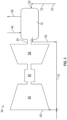
FIG. 3 is a schematic illustration of an embodiment of an electric machine and auxiliary power unit (APU) arrangement; and -
FIG. 4 is a schematic illustration of another embodiment of an electric machine and APU arrangement. - A detailed description of one or more embodiments of the disclosed apparatus and method are presented herein by way of exemplification and not limitation with reference to the Figures.
- Illustrated in
FIG. 1 is an embodiment of anelectric machine 10. Theelectric machine 10 includes arotor 12 which is rotatable about a machinecentral axis 14. Theelectric machine 10 further includes astator 16 surrounding therotor 12 and positioned radially outboard of therotor 12. Therotor 12 and thestator 16 define anair gap 18. While in the illustrated embodiment thestator 16 is located radially outboard of therotor 12, one skilled in the art will readily appreciate that the present disclosure may be readily applied to other machine configurations, such as configurations where therotor 12 is located radially outboard of thestator 16. - The
rotor 12 includes arotor core 20 and a plurality ofpermanent magnets 22 arrayed in therotor core 20. In some embodiments therotor core 20 includes a substantiallytubular rotor shaft 24 located at the machinecentral axis 14. Further, arotor sleeve 26 is located radially outboard of the plurality ofpermanent magnets 22 and circumferentially surrounding therotor core 20 to retain the plurality ofpermanent magnets 22 to therotor core 20. Therotor sleeve 26 at least partially defines theair gap 18 between therotor 12 and thestator 16. Thestator 16 includes astator core 28 with one ormore stator windings 30 installed to thestator core 28. Thestator 16 further includes astator sleeve 32 to at least partially define theair gap 18 between therotor 12 and thestator 16. - In some embodiments, as illustrated in
FIG. 1 , theelectric machine 10 is operated as a generator in which therotor 12 is driven about the machinecentral axis 14 by a power source, schematically shown at 34. Rotation of therotor 12 relative to thestator 16 generates electromagnetic interaction between thepermanent magnets 22 and thestator windings 30, resulting in electrical power being generated at thestator windings 30. - Alternatively, the
electric machine 10 may be operated as a motor as illustrated inFIG. 2 . In such configurations, an electrical current may be applied to thestator windings 30 which urges rotation of therotor 12 about the machinecentral axis 14 due to electromagnetic interaction between thestator windings 30 and thepermanent magnets 22. Therotor shaft 24 may be connected to amechanical load 36, and provides mechanical energy thereto. - The
rotor 12 and thestator 16 are at least partially contained in amachine housing 38, with therotor shaft 24 extending through ahousing opening 40 in themachine housing 38. One ormore sealing elements 42 may be located between therotor shaft 24 and themachine housing 38 to prevent leakage through thehousing opening 40. Thestator 16 is cooled by a flow of liquid, such as coolingoil 44 that enters themachine housing 38 at anoil inlet 46 and is circulated through astator chamber 48 defined between thestator sleeve 32 and themachine housing 38. Thisstator chamber 48 contains thestator core 28 and thestator windings 30, and isolates the coolingoil 44 from therotor 12, preventing the coolingoil 44 from reaching the components of therotor 12. From thestator chamber 48, the coolingoil 44 exits at anoil outlet 50. - The
rotor 12 is cooled by a flow of coolingair 52 directed from anambient air source 54 and through theair gap 18 between therotor 12 and thestator 16. The flow of coolingair 52 enters themachine housing 38 via a coolingair inlet 56 located at, for example, afirst housing end 58, and the flow of coolingair 52 exits themachine housing 38 after passing through theair gap 18 at a coolingair outlet 60 located at, for example, asecond housing end 62 opposite thefirst housing end 58. Thestator sleeve 32 and therotor sleeve 26 protect thestator 16 and therotor 12 from ambient dust and moisture that may be incidentally introduced into themachine housing 38 with the flow of cooling air 52.While one coolingair inlet 56 and onecooling air outlet 60 are illustrated, one skilled in the art will readily appreciate that in some embodiments multiplecooling air inlets 56 and multiple coolingair outlets 60 may be utilized, such as coolingair inlets 56 and/or coolingair outlets 60 circumferentially arranged and spaced apart around themachine housing 38. - Referring now to
FIG. 3 and4 , with continuing reference toFIG. 1 , in some embodiments thepower source 34 which drives theelectric machine 10 when operated as a generator is an auxiliary power unit (APU) 34 that may include, for example, a gas turbine or a thermal engine. In some embodiments, theAPU 34 includes anAPU inlet 63 through which inlet airflow is directed to acompressor section 64. The compressed airflow is mixed with fuel and combusted at acombustion chamber 66, and the flow of combustion products drive aturbine section 68. Theturbine section 68 is connected to therotor shaft 24 such that rotation of theturbine section 68 drives rotation of therotor shaft 24 and thus therotor 12. - Referring to
FIG. 3 , the flow of coolingair 52 is an ambient airflow that flows through anambient air inlet 70 and is directed toward the coolingair inlet 56 along acooling inlet pathway 72. After passing through theair gap 18 and out of the coolingair outlet 60, the flow of coolingair 52 is directed to theAPU inlet 63 via anAPU inlet pathway 74, so that the flow of coolingair 52 flows from ambient, through theelectric machine 10, then is introduced to theAPU 34 at theAPU inlet 63. - In another embodiment, illustrated in
FIG. 4 , the flow of coolingair 52 is compressor bleed flow directed from acompressor bleed outlet 76 of theAPU 34 and along anAPU bleed pathway 78 to the coolingair inlet 56. After passing through theair gap 18, the flow of coolingair 52 is directed out of the coolingair outlet 60. - Use of the hybrid cooling arrangements disclosed herein, where the
stator 16 is cooled via a flow of oil and therotor 12 is cooled via a flow of coolingair 52 directed through theair gap 18 results in a dry rotor cavity so that air bearings or magnetic bearings may be used to support therotor 12. The cooling arrangement exhibits very low windage losses at very high rotor speeds, such as those greater than 50,000 RPM. The effective cooling of both therotor 12 and thestator 16 improves performance of therotor 12 and theelectric machine 10. This improves the power to weight ratio of theelectric machine 10 when compared to other cooling schemes and improves reliability of the electric machine due to the reduced operating temperatures. - The term "about" is intended to include the degree of error associated with measurement of the particular quantity based upon the equipment available at the time of filing the application.
- The terminology used herein is for the purpose of describing particular embodiments only and is not intended to be limiting of the present disclosure. As used herein, the singular forms "a", "an" and "the" are intended to include the plural forms as well, unless the context clearly indicates otherwise. It will be further understood that the terms "comprises" and/or "comprising," when used in this specification, specify the presence of stated features, integers, steps, operations, elements, and/or components, but do not preclude the presence or addition of one or more other features, integers, steps, operations, element components, and/or groups thereof.
- While the present disclosure has been described with reference to an exemplary embodiment or embodiments, it will be understood by those skilled in the art that various changes may be made and equivalents may be substituted for elements thereof without departing from the scope of the present disclosure. In addition, many modifications may be made to adapt a particular situation or material to the teachings of the present disclosure without departing from the essential scope thereof. Therefore, it is intended that the present disclosure not be limited to the particular embodiment disclosed as the best mode contemplated for carrying out this present disclosure, but that the present disclosure will include all embodiments falling within the scope of the claims.
Claims (15)
- An electric machine, comprising:
a housing:a stator disposed in the housing and including a stator winding; anda rotor disposed in the housing configured to rotate about a machine central axis and electromagnetically interact with the stator across an air gap between the rotor and the stator, the rotor including:a rotor core;a plurality of permanent magnets disposed at the rotor core;a rotor sleeve enclosing the rotor core and the plurality of permanent magnets;wherein the stator is configured to be cooled via a flow of cooling oil; andwherein the rotor is configured to be cooled via a flow of cooling air directed through the air gap between the rotor sleeve and the stator. - The electric machine of claim 1, wherein the stator includes a stator sleeve, such that the air gap is at least partially defined between the stator sleeve and the rotor sleeve, the stator sleeve and the housing defining a stator chamber to contain the flow of cooling oil.
- The electric machine of claim 1 or 2, wherein the stator sleeve and the rotor sleeve are configured such the flow of cooling air is directed therebetween.
- The electric machine of claim 1, 2 or 3, further comprising a cooling airflow inlet at a first axial end of the housing and a cooling airflow outlet at a second axial end of the housing.
- The electric machine of any preceding claim, wherein the flow of cooling air is one of an ambient airflow or a bleed airflow from a power source operably connected to the electric machine.
- The electric machine of claim 5, wherein the power source is an auxiliary power unit.
- An electric machine system, comprising:a power source; andan electric machine as claimed in any of claims 1 to 3 operably connected to the power source to drive the electric machine.
- The electric machine system of claim 7, further comprising a cooling airflow inlet at a first axial end of the housing and a cooling airflow outlet at a second axial end of the housing, wherein the flow of cooling air is ambient airflow directed into the cooling airflow inlet, and
wherein, optionally, the flow of cooling air is directed from the cooling airflow outlet to an air inlet of the power source. - The electric machine system of claim 7, further comprising a cooling airflow inlet at a first axial end of the housing and a cooling airflow outlet at a second axial end of the housing, wherein the flow of cooling air is a bleed airflow from a compressor of the power source, and/or
wherein the power source includes one of a gas turbine engine or a thermal engine. - A method of cooling an electric machine, comprising:directing a flow of cooling oil into a stator cavity defined between a stator sleeve and a housing of the electric machine and containing one or more stator windings;cooling the one or more stator windings via the flow of cooling oil;directing a flow of cooling air through an air gap defined between a rotor sleeve of a rotor of the electric machine and the stator sleeve; andcooling one or more permanent magnets of the rotor via the flow of cooling air.
- The method of claim 10, wherein the stator sleeve separates the flow of cooling oil from the flow of cooling air.
- The method of claim 10 or 11, further comprising:flowing an ambient airflow into the air gap via a cooling airflow inlet as the flow of cooling air; andflowing the flow of cooling air out of the electric machine via a cooling airflow outlet.
- The method of claim 12, further comprising directing the flow of cooling air from the cooling airflow outlet into an air inlet of an auxiliary power unit operably connected to the electric machine.
- The method of claim 13, further comprising:combusting a mixture of fuel and the flow of cooling air at the auxiliary power unit; anddriving rotation of the rotor of the electric machine via the flow of combustion gases over a turbine of the auxiliary power unit.
- The method of claim 12, flowing a compressor bleed flow of an auxiliary power unit operably connected to the electric machine into the cooling airflow inlet at the flow of cooling air.
Applications Claiming Priority (1)
| Application Number | Priority Date | Filing Date | Title |
|---|---|---|---|
| US18/330,816 US12603551B2 (en) | 2023-06-07 | 2023-06-07 | Hybrid liquid and air cooling of high-power permanent magnet machine rotor |
Publications (1)
| Publication Number | Publication Date |
|---|---|
| EP4475403A1 true EP4475403A1 (en) | 2024-12-11 |
Family
ID=91465171
Family Applications (1)
| Application Number | Title | Priority Date | Filing Date |
|---|---|---|---|
| EP24180922.7A Pending EP4475403A1 (en) | 2023-06-07 | 2024-06-07 | Hybrid liquid and air cooling of high-power permanent magnet machine rotor |
Country Status (2)
| Country | Link |
|---|---|
| US (1) | US12603551B2 (en) |
| EP (1) | EP4475403A1 (en) |
Families Citing this family (3)
| Publication number | Priority date | Publication date | Assignee | Title |
|---|---|---|---|---|
| US12463480B2 (en) * | 2020-08-03 | 2025-11-04 | Mitsubishi Electric Corporation | Rotating electrical machine and method for manufacturing same |
| DE102022117847A1 (en) * | 2022-07-18 | 2024-01-18 | Dr. Ing. H.C. F. Porsche Aktiengesellschaft | Device for cooling an electric drive machine |
| US20250158502A1 (en) * | 2023-11-13 | 2025-05-15 | Hamilton Sundstrand Corporation | Windmill brake for an auxiliary power unit |
Citations (3)
| Publication number | Priority date | Publication date | Assignee | Title |
|---|---|---|---|---|
| US20120306206A1 (en) * | 2011-06-01 | 2012-12-06 | R&D Dynamics Corporation | Ultra high pressure turbomachine for waste heat recovery |
| WO2022117452A1 (en) * | 2020-12-02 | 2022-06-09 | Flender Gmbh | Generator/gearbox arrangement for a wind power installation with a brake |
| US20220255396A1 (en) * | 2021-02-08 | 2022-08-11 | General Electric Company | Gas turbine engines including embedded electrical machines and associated cooling systems |
Family Cites Families (6)
| Publication number | Priority date | Publication date | Assignee | Title |
|---|---|---|---|---|
| US2285960A (en) * | 1940-08-02 | 1942-06-09 | Carl J Fechheimer | Dynamoelectric machine |
| US6393825B1 (en) * | 2000-01-25 | 2002-05-28 | General Electric Company | System for pressure modulation of turbine sidewall cavities |
| DE102016207517A1 (en) | 2016-05-02 | 2017-11-02 | Siemens Aktiengesellschaft | Propulsion system for aircraft with electric generator |
| US10778056B2 (en) * | 2017-05-16 | 2020-09-15 | Hamilton Sunstrand Corporation | Generator with enhanced stator cooling and reduced windage loss |
| US10801410B2 (en) | 2018-04-12 | 2020-10-13 | Raytheon Technologies Corporation | Thermal management of tail cone mounted generator |
| US11984762B2 (en) * | 2021-10-04 | 2024-05-14 | Rolls-Royce Electrical Norway AS | Electric machine stator tube |
-
2023
- 2023-06-07 US US18/330,816 patent/US12603551B2/en active Active
-
2024
- 2024-06-07 EP EP24180922.7A patent/EP4475403A1/en active Pending
Patent Citations (3)
| Publication number | Priority date | Publication date | Assignee | Title |
|---|---|---|---|---|
| US20120306206A1 (en) * | 2011-06-01 | 2012-12-06 | R&D Dynamics Corporation | Ultra high pressure turbomachine for waste heat recovery |
| WO2022117452A1 (en) * | 2020-12-02 | 2022-06-09 | Flender Gmbh | Generator/gearbox arrangement for a wind power installation with a brake |
| US20220255396A1 (en) * | 2021-02-08 | 2022-08-11 | General Electric Company | Gas turbine engines including embedded electrical machines and associated cooling systems |
Also Published As
| Publication number | Publication date |
|---|---|
| US12603551B2 (en) | 2026-04-14 |
| US20240413711A1 (en) | 2024-12-12 |
Similar Documents
| Publication | Publication Date | Title |
|---|---|---|
| US12603551B2 (en) | Hybrid liquid and air cooling of high-power permanent magnet machine rotor | |
| JP5722309B2 (en) | Integrated brushless starter / generator system | |
| CN109209642B (en) | Electrical machine | |
| CA2612813C (en) | Electric power generation using power turbine aft of lpt | |
| EP3675332A1 (en) | Rotor for an electric machine | |
| US8745990B2 (en) | Gas turbine engine with integrated electric starter/generator | |
| US8125110B2 (en) | Two-stage cooling fan for an electric generator | |
| US20040146411A1 (en) | Rotary machine cooling system | |
| US6943469B2 (en) | Supplemented zonal ventilation system for electric generator | |
| US20110252807A1 (en) | Accessory gearbox with a starter/generator | |
| US10381900B2 (en) | Method and assembly of an electric machine | |
| KR20100029084A (en) | Turbocharger with electric motor | |
| EP3404802A1 (en) | Generator with enhanced stator cooling and reduced windage loss | |
| EP3628598B1 (en) | Power converter cooling | |
| CN115833470A (en) | Method and apparatus for cooling rotor assembly | |
| EP3961867A1 (en) | Electric machine having an electrically insulative manifold | |
| EP4183996A1 (en) | Cooling system for tail cone mounted generator | |
| CN108964305B (en) | Motor and gas turbine comprising same | |
| US11988150B2 (en) | Bypass turbine engine comprising at least one accessory or equipment | |
| US20190190336A1 (en) | Method and apparatus for cooling a rotor assembly | |
| US20210340878A1 (en) | Turbo-generator with integral cooling | |
| US12614940B2 (en) | Cooling of high-power permanent magnet machine rotor | |
| EP3435524A1 (en) | Electrical machine apparatus | |
| EP4096069A1 (en) | Aircraft turbo-alternator | |
| CN110556973A (en) | Systems for cooling motors |
Legal Events
| Date | Code | Title | Description |
|---|---|---|---|
| PUAI | Public reference made under article 153(3) epc to a published international application that has entered the european phase |
Free format text: ORIGINAL CODE: 0009012 |
|
| STAA | Information on the status of an ep patent application or granted ep patent |
Free format text: STATUS: THE APPLICATION HAS BEEN PUBLISHED |
|
| AK | Designated contracting states |
Kind code of ref document: A1 Designated state(s): AL AT BE BG CH CY CZ DE DK EE ES FI FR GB GR HR HU IE IS IT LI LT LU LV MC ME MK MT NL NO PL PT RO RS SE SI SK SM TR |
|
| STAA | Information on the status of an ep patent application or granted ep patent |
Free format text: STATUS: REQUEST FOR EXAMINATION WAS MADE |
|
| 17P | Request for examination filed |
Effective date: 20250610 |