EP4475394A1 - Power tool motor rotor configurations - Google Patents
Power tool motor rotor configurations Download PDFInfo
- Publication number
- EP4475394A1 EP4475394A1 EP24179270.4A EP24179270A EP4475394A1 EP 4475394 A1 EP4475394 A1 EP 4475394A1 EP 24179270 A EP24179270 A EP 24179270A EP 4475394 A1 EP4475394 A1 EP 4475394A1
- Authority
- EP
- European Patent Office
- Prior art keywords
- permanent magnet
- rotor
- consequent pole
- motor
- lamination
- Prior art date
- Legal status (The legal status is an assumption and is not a legal conclusion. Google has not performed a legal analysis and makes no representation as to the accuracy of the status listed.)
- Pending
Links
- 239000000696 magnetic material Substances 0.000 claims abstract description 9
- 238000003475 lamination Methods 0.000 claims description 147
- 238000004804 winding Methods 0.000 claims description 27
- 230000014759 maintenance of location Effects 0.000 claims description 18
- 239000000463 material Substances 0.000 claims description 12
- 238000002347 injection Methods 0.000 claims description 11
- 239000007924 injection Substances 0.000 claims description 11
- 229910052761 rare earth metal Inorganic materials 0.000 claims description 9
- 150000002910 rare earth metals Chemical class 0.000 claims description 9
- 239000004033 plastic Substances 0.000 description 8
- 238000004891 communication Methods 0.000 description 7
- 238000000034 method Methods 0.000 description 6
- 229910001220 stainless steel Inorganic materials 0.000 description 5
- 239000010935 stainless steel Substances 0.000 description 5
- 238000013500 data storage Methods 0.000 description 4
- 239000012790 adhesive layer Substances 0.000 description 3
- 230000006870 function Effects 0.000 description 3
- 230000008569 process Effects 0.000 description 3
- 230000009467 reduction Effects 0.000 description 3
- 229920000049 Carbon (fiber) Polymers 0.000 description 2
- 230000008901 benefit Effects 0.000 description 2
- 239000004917 carbon fiber Substances 0.000 description 2
- 238000010276 construction Methods 0.000 description 2
- 238000010586 diagram Methods 0.000 description 2
- 230000003116 impacting effect Effects 0.000 description 2
- 238000004519 manufacturing process Methods 0.000 description 2
- VNWKTOKETHGBQD-UHFFFAOYSA-N methane Chemical compound C VNWKTOKETHGBQD-UHFFFAOYSA-N 0.000 description 2
- 239000002991 molded plastic Substances 0.000 description 2
- 230000003287 optical effect Effects 0.000 description 2
- 229920001651 Cyanoacrylate Polymers 0.000 description 1
- 239000004593 Epoxy Substances 0.000 description 1
- 230000005355 Hall effect Effects 0.000 description 1
- MWCLLHOVUTZFKS-UHFFFAOYSA-N Methyl cyanoacrylate Chemical compound COC(=O)C(=C)C#N MWCLLHOVUTZFKS-UHFFFAOYSA-N 0.000 description 1
- 229910052779 Neodymium Inorganic materials 0.000 description 1
- 229910000831 Steel Inorganic materials 0.000 description 1
- 239000004809 Teflon Substances 0.000 description 1
- 229920006362 Teflon® Polymers 0.000 description 1
- NIXOWILDQLNWCW-UHFFFAOYSA-N acrylic acid group Chemical group C(C=C)(=O)O NIXOWILDQLNWCW-UHFFFAOYSA-N 0.000 description 1
- 239000000853 adhesive Substances 0.000 description 1
- 230000001070 adhesive effect Effects 0.000 description 1
- 230000008878 coupling Effects 0.000 description 1
- 238000010168 coupling process Methods 0.000 description 1
- 238000005859 coupling reaction Methods 0.000 description 1
- 230000007423 decrease Effects 0.000 description 1
- 230000003247 decreasing effect Effects 0.000 description 1
- 238000007599 discharging Methods 0.000 description 1
- 238000005259 measurement Methods 0.000 description 1
- 229910052751 metal Inorganic materials 0.000 description 1
- 239000002184 metal Substances 0.000 description 1
- -1 neodymium Chemical class 0.000 description 1
- QEFYFXOXNSNQGX-UHFFFAOYSA-N neodymium atom Chemical compound [Nd] QEFYFXOXNSNQGX-UHFFFAOYSA-N 0.000 description 1
- 239000004417 polycarbonate Substances 0.000 description 1
- 229920000515 polycarbonate Polymers 0.000 description 1
- 239000010959 steel Substances 0.000 description 1
Images







Classifications
-
- H—ELECTRICITY
- H02—GENERATION; CONVERSION OR DISTRIBUTION OF ELECTRIC POWER
- H02K—DYNAMO-ELECTRIC MACHINES
- H02K1/00—Details of the magnetic circuit
- H02K1/06—Details of the magnetic circuit characterised by the shape, form or construction
- H02K1/22—Rotating parts of the magnetic circuit
- H02K1/27—Rotor cores with permanent magnets
- H02K1/2706—Inner rotors
- H02K1/272—Inner rotors the magnetisation axis of the magnets being perpendicular to the rotor axis
- H02K1/274—Inner rotors the magnetisation axis of the magnets being perpendicular to the rotor axis the rotor consisting of two or more circumferentially positioned magnets
- H02K1/2746—Inner rotors the magnetisation axis of the magnets being perpendicular to the rotor axis the rotor consisting of two or more circumferentially positioned magnets the rotor consisting of magnets arranged with the same polarity, e.g. consequent pole type
-
- H—ELECTRICITY
- H02—GENERATION; CONVERSION OR DISTRIBUTION OF ELECTRIC POWER
- H02K—DYNAMO-ELECTRIC MACHINES
- H02K1/00—Details of the magnetic circuit
- H02K1/06—Details of the magnetic circuit characterised by the shape, form or construction
- H02K1/22—Rotating parts of the magnetic circuit
- H02K1/27—Rotor cores with permanent magnets
- H02K1/2706—Inner rotors
- H02K1/272—Inner rotors the magnetisation axis of the magnets being perpendicular to the rotor axis
- H02K1/274—Inner rotors the magnetisation axis of the magnets being perpendicular to the rotor axis the rotor consisting of two or more circumferentially positioned magnets
- H02K1/2753—Inner rotors the magnetisation axis of the magnets being perpendicular to the rotor axis the rotor consisting of two or more circumferentially positioned magnets the rotor consisting of magnets or groups of magnets arranged with alternating polarity
- H02K1/276—Magnets embedded in the magnetic core, e.g. interior permanent magnets [IPM]
-
- H—ELECTRICITY
- H02—GENERATION; CONVERSION OR DISTRIBUTION OF ELECTRIC POWER
- H02K—DYNAMO-ELECTRIC MACHINES
- H02K1/00—Details of the magnetic circuit
- H02K1/02—Details of the magnetic circuit characterised by the magnetic material
-
- H—ELECTRICITY
- H02—GENERATION; CONVERSION OR DISTRIBUTION OF ELECTRIC POWER
- H02K—DYNAMO-ELECTRIC MACHINES
- H02K1/00—Details of the magnetic circuit
- H02K1/06—Details of the magnetic circuit characterised by the shape, form or construction
- H02K1/22—Rotating parts of the magnetic circuit
-
- H—ELECTRICITY
- H02—GENERATION; CONVERSION OR DISTRIBUTION OF ELECTRIC POWER
- H02K—DYNAMO-ELECTRIC MACHINES
- H02K21/00—Synchronous motors having permanent magnets; Synchronous generators having permanent magnets
- H02K21/12—Synchronous motors having permanent magnets; Synchronous generators having permanent magnets with stationary armatures and rotating magnets
- H02K21/14—Synchronous motors having permanent magnets; Synchronous generators having permanent magnets with stationary armatures and rotating magnets with magnets rotating within the armatures
- H02K21/16—Synchronous motors having permanent magnets; Synchronous generators having permanent magnets with stationary armatures and rotating magnets with magnets rotating within the armatures having annular armature cores with salient poles
-
- H—ELECTRICITY
- H02—GENERATION; CONVERSION OR DISTRIBUTION OF ELECTRIC POWER
- H02K—DYNAMO-ELECTRIC MACHINES
- H02K7/00—Arrangements for handling mechanical energy structurally associated with dynamo-electric machines, e.g. structural association with mechanical driving motors or auxiliary dynamo-electric machines
- H02K7/14—Structural association with mechanical loads, e.g. with hand-held machine tools or fans
- H02K7/145—Hand-held machine tool
-
- H—ELECTRICITY
- H02—GENERATION; CONVERSION OR DISTRIBUTION OF ELECTRIC POWER
- H02K—DYNAMO-ELECTRIC MACHINES
- H02K2213/00—Specific aspects, not otherwise provided for and not covered by codes H02K2201/00 - H02K2211/00
- H02K2213/03—Machines characterised by numerical values, ranges, mathematical expressions or similar information
Definitions
- Embodiments described herein relate to a motor of a power tool.
- Power tools described herein include a battery pack interface configured to receive a battery pack and a motor.
- the motor includes a stator including a plurality of stator teeth configured to receive a plurality of stator windings, and a rotor configured to rotate with respect to the stator.
- the rotor includes a first permanent magnet within the rotor, a second permanent magnet within the rotor, and a consequent pole located between the first permanent magnet and the second permanent magnet.
- the consequent pole has a length and a width.
- the consequent pole is made of a non-magnetic material.
- the first permanent magnet and the second permanent magnet are composed of a rare earth metal.
- the rotor includes a lamination stack including an inner lamination portion and an outer lamination portion, wherein an air gap is located between the inner lamination portion and the outer lamination portion.
- the consequent pole is constructed from the lamination stack.
- the inner lamination portion includes a first axial support portion
- the outer lamination portion includes a second axial support portion
- the rotor includes an outer diameter of approximately 22 millimeters.
- the rotor further includes a lamination stack, a first slot including a first magnet housing portion configured to receive the first permanent magnet, a second slot including a second magnet housing portion configured to receive the second permanent magnet, and a plurality of air gaps, wherein each of the plurality of air gaps includes an injection molded material.
- one of the plurality of air gaps is enclosed by an outer rib of the lamination stack.
- Power tools described herein include a battery pack interface configured to receive a battery pack and a consequent pole motor.
- the consequent pole motor includes a stator including a plurality of stator teeth configured to receive a plurality of stator windings, and a rotor configured to rotate with respect to the stator.
- the rotor includes a first permanent magnet within a first slot of the rotor, a second permanent magnet within a second slot of the rotor, a first consequent pole between the first permanent magnet and the second permanent magnet, the first consequent pole having a first length and a first width, and a second consequent pole between the first permanent magnet and the second permanent magnet, the second consequent pole having a second length and a second width.
- the first permanent magnet and the second permanent magnet are composed of a rare earth metal.
- the rotor includes a lamination stack including an inner lamination portion and an outer lamination portion, wherein an air gap is located between the inner lamination portion and the outer lamination portion, and wherein the air gap is enclosed by an outer rib of the lamination stack.
- the first consequent pole and the second consequent pole are constructed from the lamination stack.
- the inner lamination portion includes a first axial support portion
- the outer lamination portion includes a second axial support portion
- the rotor further includes a lamination stack, a first slot including a first magnet housing portion configured to receive the first permanent magnet, a second slot including a second magnet housing portion configured to receive the second permanent magnet, and a plurality of air gaps, wherein each of the plurality of air gaps includes an injection molded material, wherein one of the plurality of air gaps is enclosed by an outer rib of the lamination stack.
- Consequent pole motors described herein include a stator including a plurality of stator teeth configured to receive a plurality of stator windings, and a rotor configured to rotate around the stator.
- the rotor includes a lamination stack including an inner lamination portion and an outer lamination portion, a first permanent magnet located within a first slot of the lamination stack, the first slot being between the inner lamination portion and the outer lamination portion, a second permanent magnet located within a second slot of the lamination stack, the second slot being between the inner lamination portion and the outer lamination portion, a first consequent pole located between the first permanent magnet and the second permanent magnet, the first consequent pole having a first length and a first width, a second consequent pole located between the first permanent magnet and the second permanent magnet, the second consequent pole having a second length and a second width, and an air gap located between the inner lamination portion and the outer lamination portion.
- the first consequent pole and the second consequent pole are constructed from the lamination stack.
- the first permanent magnet and the second permanent magnet are composed of a rare earth metal, and the first consequent pole and the second consequent pole are constructed from a non-magnetic material.
- the air gap is enclosed by an outer rib of the lamination stack.
- the air gap is filled with an injection molded material.
- the rotor further includes a first retention portion configured to retain the inner lamination portion and a second retention portion configured to retain the outer lamination portion, and the first retention portion and the second retention portion are connected via a plate.
- embodiments may include hardware, software, and electronic components or modules that, for purposes of discussion, may be illustrated and described as if the majority of the components were implemented solely in hardware.
- the electronic-based aspects may be implemented in software (e.g., stored on non-transitory computer-readable medium) executable by one or more processing units, such as a microprocessor and/or application specific integrated circuits ("ASICs").
- ASICs application specific integrated circuits
- servers can include one or more processing units, one or more computer-readable medium modules, one or more input/output interfaces, and various connections (e.g., a system bus) connecting the components.
- an apparatus, method, or system for example, as including a controller, control unit, electronic processor, computing device, logic element, module, memory module, communication channel or network, or other element configured in a certain manner, for example, to perform multiple functions
- the claim or claim element should be interpreted as meaning one or more of such elements where any one of the one or more elements is configured as claimed, for example, to make any one or more of the recited multiple functions, such that the one or more elements, as a set, perform the multiple functions collectively.
- FIG. 1 illustrates a power tool 100 including a permanent magnet motor.
- the power tool 100 is, for example, a hammer drill including a housing 102.
- the housing 102 includes a handle portion 104 and motor housing portion 106.
- the power tool 100 further includes an output driver 108 (illustrated as a chuck), a trigger 110, and a battery pack interface 112.
- the battery pack interface 112 is configured to mechanically and electrically connect to or receive a power tool battery pack.
- FIG. 1 illustrates a hammer drill
- the components described herein are incorporated into other types of power tools including drill-drivers, impact drivers, impact wrenches, angle grinders, circular saws, reciprocating saws, plate compactors, core drills, string trimmers, leaf blowers, vacuums, and the like.
- a permanent magnet motor power tool such as power tool 100
- switching elements are selectively enabled and disabled by control signals from a controller to selectively apply power from a power source (e.g., a battery pack) to drive a permanent magnet motor.
- a power source e.g., a battery pack
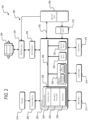
- FIG. 2 illustrates a control system 200 for the power tool 100.
- the control system 200 includes a controller 202.
- the controller 202 is electrically and/or communicatively connected to a variety of modules or components of the power tool 100.
- the illustrated controller 202 is electrically connected to a motor 204, a battery pack interface 206, a trigger switch 208 (connected to a trigger 210), one or more sensors or sensing circuits 212, one or more indicators 214, a user input module 216, a power input module 218, an inverter bridge or FET switching module 220 (e.g., including a plurality of switching FETs), and gate drivers 224 for driving the FET switching module 220.
- motor 204 is a permanent magnet motor.
- the controller 202 includes combinations of hardware and software that are operable to, among other things, control the operation of the power tool 100, monitor the operation of the power tool 100, activate the one or more indicators 214 (e.g., an LED), etc.
- the controller 202 includes a plurality of electrical and electronic components that provide power, operational control, and protection to the components and modules within the controller 202 and/or the power tool 100.
- the controller 202 includes, among other things, a processing unit 226 (e.g., a microprocessor, a microcontroller, an electronic controller, an electronic processor, or another suitable programmable device), a memory 228, input units 230, and output units 232.
- the processing unit 226 includes, among other things, a control unit 234, an arithmetic logic unit (“ALU") 236, and a plurality of registers 238, and is implemented using a known computer architecture (e.g., a modified Harvard architecture, a von Neumann architecture, etc.).
- ALU arithmetic logic unit
- the processing unit 226, the memory 228, the input units 230, and the output units 232, as well as the various modules or circuits connected to the controller 202 are connected by one or more control and/or data buses (e.g., common bus 240).
- the control and/or data buses are shown generally in FIG. 2 for illustrative purposes. The use of one or more control and/or data buses for the interconnection between and communication among the various modules, circuits, and components would be known to a person skilled in the art in view of the embodiments described herein.
- the memory 228 is a non-transitory computer readable medium and includes, for example, a program storage area and a data storage area.
- the program storage area and the data storage area can include combinations of different types of memory, such as a ROM, a RAM (e.g., DRAM, SDRAM, etc.), EEPROM, flash memory, a hard disk, an SD card, or other suitable magnetic, optical, physical, or electronic memory devices.
- the processing unit 226 is connected to the memory 228 and executes software instructions that are capable of being stored in a RAM of the memory 228 (e.g., during execution), a ROM of the memory 228 (e.g., on a generally permanent basis), or another non-transitory computer readable medium such as another memory or a disc.
- Software included in the implementation of the power tool 100 can be stored in the memory 228 of the controller 202.
- the software includes, for example, firmware, one or more applications, program data, filters, rules, one or more program modules, and other executable instructions.
- the controller 202 is configured to retrieve from the memory 228 and execute, among other things, instructions related to the control processes and methods described herein. In other constructions, the controller 202 includes additional, fewer, or different components.
- the battery pack interface 206 includes a combination of mechanical components (e.g., rails, grooves, latches, etc.) and electrical components (e.g., one or more terminals) configured to and operable for interfacing (e.g., mechanically, electrically, and communicatively connecting) with a battery pack.
- mechanical components e.g., rails, grooves, latches, etc.
- electrical components e.g., one or more terminals
- the power input module 218 includes combinations of active and passive components to regulate or control the power received from the battery pack 300 prior to power being provided to the controller 202.
- the battery pack interface 206 also supplies power to the FET switching module 220 to be switched by the switching FETs to selectively provide power to the motor 204.
- the battery pack interface 206 also includes, for example, a communication line 242 for providing a communication line or link between the controller 202 and the battery pack 300.
- the sensor circuits 212 include one or more current sensors, one or more speed sensors, one or more Hall effect sensors, one or more temperature sensors, etc.
- the indicators 214 include, for example, one or more light-emitting diodes ("LEDs").
- the indicators 214 can be configured to display conditions of, or information associated with, the power tool 100.
- the indicators 214 are configured to indicate measured electrical characteristics of the power tool 100, the status of the power tool, the status the motor 204, etc.
- the user input module 216 is operably coupled to the controller 202 to, for example, select a forward mode of operation or a reverse mode of operation, a torque and/or speed setting for the power tool 100 (e.g., using torque and/or speed switches), etc.
- the user input module 216 includes a combination of digital and analog input or output devices required to achieve a desired level of operation for the power tool 100, such as one or more knobs, one or more dials, one or more switches, one or more buttons, etc.
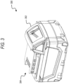
- FIG. 3 illustrates a battery pack 300.
- the battery pack 300 includes a housing 302 and an interface portion 304 for connecting the battery pack 300 to a power tool, such as the power tool 100.
- FIG. 4 illustrates a control system for the battery pack 300.
- the control system includes a controller 400.
- the controller 400 is electrically and/or communicatively connected to a variety of modules or components of the battery pack 300.
- the illustrated controller 400 is connected to one or more battery cells 402 and an interface 404 (e.g., the interface portion 304 of the battery pack 300 illustrated in FIG. 3 ).
- the controller 400 is also connected to one or more voltage sensors or voltage sensing circuits 406, one or more current sensors or current sensing circuits 408, and one or more temperature sensors or temperature sensing circuits 410.
- the controller 400 includes combinations of hardware and software that are operable to, among other things, control the operation of the battery pack 300, monitor a condition of the battery pack 300, enable or disable charging of the battery pack 300, enable or disable discharging of the battery pack 300, etc.
- the controller 400 includes a plurality of electrical and electronic components that provide power, operational control, and protection to the components and modules within the controller 400 and/or the battery pack 300.
- the controller 400 includes, among other things, a processing unit 412 (e.g., a microprocessor, a microcontroller, an electronic processor, an electronic controller, or another suitable programmable device), a memory 414, input units 416, and output units 418.
- the processing unit 412 includes, among other things, a control unit 420, an ALU 422, and a plurality of registers 424, and is implemented using a known computer architecture (e.g., a modified Harvard architecture, a von Neumann architecture, etc.).
- the processing unit 412, the memory 414, the input units 416, and the output units 418, as well as the various modules or circuits connected to the controller 400 are connected by one or more control and/or data buses (e.g., common bus 426).
- the control and/or data buses are shown generally in FIG. 4 for illustrative purposes. The use of one or more control and/or data buses for the interconnection between and communication among the various modules, circuits, and components would be known to a person skilled in the art in view of the embodiments described herein.
- the memory 414 is a non-transitory computer readable medium and includes, for example, a program storage area and a data storage area.
- the program storage area and the data storage area can include combinations of different types of memory, such as a ROM, a RAM (e.g., DRAM, SDRAM, etc.), EEPROM, flash memory, a hard disk, an SD card, or other suitable magnetic, optical, physical, or electronic memory devices.
- the processing unit 412 is connected to the memory 414 and executes software instructions that are capable of being stored in a RAM of the memory 414 (e.g., during execution), a ROM of the memory 414 (e.g., on a generally permanent basis), or another non-transitory computer readable medium such as another memory or a disc.
- Software included in the implementation of the battery pack 300 can be stored in the memory 414 of the controller 400.
- the software includes, for example, firmware, one or more applications, program data, filters, rules, one or more program modules, and other executable instructions.
- the controller 400 is configured to retrieve from the memory 414 and execute, among other things, instructions related to the control processes and methods described herein. In other constructions, the controller 400 includes additional, fewer, or different components.
- the interface 404 includes a combination of mechanical components (e.g., rails, grooves, latches, etc.) and electrical components (e.g., one or more terminals) configured to and operable for interfacing (e.g., mechanically, electrically, and communicatively connecting) the battery pack 300 with another device (e.g., a power tool, a battery pack charger, etc.).
- the interface 404 is configured to communicatively connect to the controller 400 via a communications line 428.
- FIG. 5 illustrates an internal permanent magnet motor rotor 500, according to some embodiments.
- the rotor 500 includes a lamination stack 505.
- the lamination stack 505 includes an inner lamination portion 510 and an outer lamination portion 515.
- the rotor 500 includes a plurality of slots 520, and each slot includes a magnet housing portion 525 configured to receive a magnet 530.
- the magnet 530 includes a length 535 and a width 540.
- the rotor 500 also includes a rotor sleeve 545.
- the rotor sleeve 545 is made of a carbon fiber material.
- the carbon fiber sleeve is made of another material, such as a plastic, a non-magnetic metal, a polycarbonate, or the like.
- the rotor 500 is configured to rotate with respect to a stator.
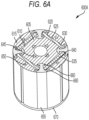
- FIG. 6A-6D illustrate internal permanent magnet motor rotors 600A, 600B, 600C, 600D, according to some embodiments.
- the rotor 600A includes a lamination stack 605.
- the lamination stack 605 includes an inner lamination portion 610 and an outer lamination portion 615.
- the rotor 600A includes a plurality of slots 620, and each slot 620 includes a magnet housing portion 625 configured to receive a magnet 630.
- the magnet 630 includes a length 635 and a width 640.
- the inner lamination portion 610 of the lamination stack 605 includes a first axial support portion 645.
- the outer lamination portion 615 of the lamination stack 605 includes a second axial support portion 650.
- a plastic mold 655 is configured to retain the inner lamination portion 610 and the outer lamination portion 615 of the lamination stack 605.
- the plastic mold 655 may include a first retention portion 660 configured to retain the plastic mold 655 to the inner lamination portion 610, and a second retention portion 665 configured to retain the plastic mold to the outer lamination portion 615.
- the plastic mold 655 also includes a plate 670 configured to connect the first retention portion 660 and the second retention portion 665 to each other, thereby creating a single secure element for retaining the inner lamination portion 610, the outer lamination portion 615, and the magnets 630.
- the rotor 600A is configured to rotate with respect to a stator.
- FIG. 6B illustrates the permanent magnet motor rotor 600B.
- the rotor 600B includes the first axial support portion 645, the first retention portion 660, the second retention portion 665 and the plate 670 made of injection molded plastic, and the second axial support portion 650 and a plate portion 675 made of stainless-steel.
- the stainless-steel plate portion 675 is configured to connect to the second axial support portion 650.
- the rotor 600B is configured to rotate with respect to a stator.
- FIG 6C illustrates another embodiment for the rotor 600C.
- both the first axial support portion 645 and the second axial support portion 650 are made of stainless-steel, and are configured to connect to the stainless-steel plate portion 675.
- the rotor 600C is configured to rotate with respect to a stator.
- FIG 6D illustrates another embodiment for the rotor 600D.
- an inner adhesive layer 680 and an outer adhesive layer 685 are used to hold the magnets 630 and the lamination stack 605 together.
- the adhesive used in the inner and outer adhesive layers (680, 685) may be an epoxy, a structural acrylic, cyanoacrylate, or other type of bonding material. In some instances, a Teflon mold may be used during the assembly process.
- the rotor 600D is configured to rotate with respect to a stator.
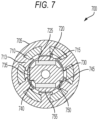
- FIG. 7 illustrates a consequent pole motor 700, according to some embodiments.
- the motor 700 includes a stator 705 and a plurality of stator winding slots 710.
- the stator also includes stator teeth 713.
- the plurality of stator winding slots 710 are configured to receive a plurality of windings, wound around the stator teeth 713.
- the motor 700 also includes a rotor 715.
- the rotor 715 includes a plurality of permanent magnet slots 720 configured to receive permanent magnets 725.
- the rotor 715 includes a plurality of consequent poles 730.
- the consequent poles 730 have a length 735 and a width 740. In some embodiments, each of the consequent poles includes the same length and width.
- the consequent poles have different lengths and widths.
- the length 735 or the width 740 of the consequent pole 730 is controlled to impact the performance of the motor 700.
- the impacts of the dimensions of the consequent pole 730 are illustrated in FIG. 8 and described in detail below.
- the motor 700 also includes an air gap 745 between the plurality of permanent magnets 725 and the consequent poles 730.
- the air gaps 745 are enclosed by an outer rib 750 of the lamination stack 755.
- the air gaps 745 are ribless.
- the consequent poles 730 are made of a non-magnetic material (e.g., rotor laminations, etc.).
- the consequent pole motor 700 can include any of the motor rotor features described above with respect to FIGS. 5 , 6A , 6B , 6C , and 6D .
- the rotor 715 is configured to rotate with respect to a stator.
- FIG. 8 graphically illustrates the performance of an internal permanent magnet (“IPM") motor compared to the consequent pole motor 700, according to some embodiments.
- the graph includes IPM motor efficiency 805, IPM motor output power 815, IPM motor current 825, and IPM motor speed 835 when compared to a motor torque.
- the graph also includes consequent pole motor efficiency 810, consequent pole motor output power 820, consequent pole motor current 830, and consequent pole motor speed 840 when compared to a motor torque.
- the graph 800 also includes a highlighted operating region 845, within which both the IPM motor and the motor 700 nominally operate. As evidenced by the graph 800, the performance for both IPM motor and the motor 700 are similar within the operating region 845.
- the IPM motor represented on the graph 800 has a magnet mass of approximately 55g, while the motor 700 has approximately a 28% mass reduction without significantly impacting the performance of the motor 700 within the operating region 845.
- FIG. 9 illustrates a consequent pole motor 900, according to some embodiments.
- the motor 900 includes a stator 905 and a plurality of stator winding slots 910.
- the stator also includes stator teeth 913.
- the plurality of stator winding slots 910 are configured to receive a plurality of windings, wound around the stator teeth 913.
- the stator 905 includes air gaps 914 between the plurality of stator winding slots 910.
- the motor 900 also includes a rotor 915.
- the rotor 915 includes a plurality of permanent magnet slots 920 configured to receive permanent magnets 925.
- the rotor 915 includes a plurality of consequent poles 930.
- the consequent poles 930 have a length 935 and a width 940.
- each of the consequent poles includes the same length and width. In other embodiments, the consequent poles have different lengths and widths. In some embodiments, the length 935 or the width 940 of the consequent pole 930 are controlled to impact the performance of the motor 900. The impacts of the dimensions of the consequent pole 930 are illustrated in FIG. 10 and described in detail below.
- the motor 900 also includes air gaps 945 between the plurality of magnets 925 and the consequent poles 930. In some embodiments, the air gaps 945 are enclosed by an outer rib 950 of the lamination stack 955. In some embodiments, the air gaps 945 are ribless.
- the consequent poles 930 are made of a non-magnetic material (e.g., rotor laminations, etc.).
- the consequent pole motor 900 can include any of the motor rotor features described above with respect to FIGS. 5 , 6A , 6B , 6C , and 6D .
- the rotor 915 is configured to rotate with respect to a stator.
- FIG. 10 provides a graph 1000 that illustrates a performance comparison between an internal permanent magnet motor and the motor 900.
- the graph includes IPM motor efficiency 1005, IPM motor output power 1015, IPM motor current 1025, and IPM motor speed 1035 when compared to a motor torque.
- the graph also includes consequent pole motor efficiency 1010, consequent pole motor output power 1020, consequent pole motor current 1030, and consequent pole motor speed 1040 when compared to a motor torque.
- the graph 1000 also includes a target operating load 1045 of approximately 0.19Nm, and a target operating speed 1050 of approximately 42,000 RPM.
- the IPM motor performs with a greater efficiency 1005 and output power 1015 than the motor 900 efficiency 1010 and output power 1020.
- the performance for both IPM motor and the motor 900 are similar within the target operating load 1045 region.
- the IPM motor represented on the graph 1000 has a magnet mass of approximately 79g, while the motor 900 has approximately a 36% mass reduction without significantly impacting the performance of the motor 900 within the target operating load 1045 region.
- FIG. 11 illustrates an internal permanent magnet motor 1100, according to some embodiments.
- the motor 1100 includes a stator 1105 and a plurality of stator winding slots 1110.
- the stator 1105 also includes stator teeth 1113.
- the plurality of stator winding slots 1110 are configured to receive a plurality of windings, wound around the stator teeth 1113.
- the motor 1100 also includes a rotor 1115.
- the rotor 1115 includes a plurality of slots 1120, and each slot 1120 includes a magnet housing portion 1125 configured to receive a magnet 1130.
- the magnets 1130 include a length 1135 and a width 1140.
- the rotor 1115 further includes a lamination stack 1145 including an inner lamination portion 1150 and an outer lamination portion 1155.
- the inner lamination portion 1150 of the lamination stack 1145 includes a first axial support portion 1160.
- the outer lamination portion 1155 of the lamination stack 1145 includes a second axial support portion 1165.
- a plastic mold is configured to retain the inner lamination portion and the outer lamination portion as previously described, and as illustrated in FIGS. 6A-6D .
- the motor 1100 does not include outer steel ribs that would otherwise enclose the magnets 1130.
- FIG. 12 is a graph 1200 that illustrates a performance comparison between a conventional internal permanent magnet motor and the motor 1100.
- the graph 1200 includes conventional IPM motor efficiency 1205, conventional IPM motor output power 1215, conventional IPM motor current 1225, and conventional IPM motor speed 1235 when compared to a motor torque.
- the graph 1200 also includes motor efficiency 1210, output power 1220, motor current 1230, and motor speed 1240 for the motor 1100 when compared to a motor torque.
- the conventional IPM motor performs with approximately the same efficiency 1205 as the motor 1100 efficiency 1210.
- the motor 1100 produces, for example, approximately 5% more power than the conventional IPM motor.
- FIG. 13 illustrates a permanent magnet motor, according to some embodiments.
- the motor 1300 is configured for use in the power tool 100.
- the motor 1300 includes an internal permanent magnet configuration.
- the motor 1300 includes a stator 1305 and a plurality of stator winding slots 1310.
- the plurality of stator winding slots 1310 are configured to receive a plurality of windings.
- the motor 1300 also includes a rotor 1315.
- the rotor has an outer diameter of 22 millimeters ("mm").
- the rotor 1315 includes a plurality of slots 1320, and each slot includes a magnet housing portion 1325 configured to receive a magnet 1330.
- the magnet 1330 includes a length 1335 and a width 1340.
- the rotor 1315 further includes a lamination stack 1345 and air gaps 1350.
- the air gaps 1350 include a length 1355 and a width 1360.
- the size of the air gaps 1350, or the length 1355 and width 1360 of the air gaps 1350 increases or decreases along with the size of the magnet 1330.
- the length 1335 of the magnet 1330 may be decreased in order to reduce the manufacturing cost of the motor 1300. Accordingly, the length 1355 of the air gap may be increased along with the reduced magnet 1330 size.
- the lamination stack 1345 is configured to occupy the space of the reduced magnet 1330 length 1335.
- FIG. 14 illustrates a permanent magnet motor, according to some embodiments.
- the motor 1400 includes a stator 1405 and a plurality of stator winding slots 1410.
- the stator also includes stator teeth 1413.
- the plurality of stator winding slots 1410 are configured to receive a plurality of windings, wound around the stator teeth 1413.
- the motor 1400 also includes a rotor 1415.
- the rotor 1415 includes a plurality of slots 1420, and each slot includes a magnet housing portion 1425 configured to receive a magnet 1430.
- the magnets 1430 includes a length 1435 and a width 1440.
- the rotor further includes a lamination stack 1445 including an inner lamination portion 1450 and an outer lamination portion 1455.
- the inner lamination portion 1450 of the lamination stack 1445 includes a first axial support portion 1460.
- the motor 1400 is similar to the motor 1100.
- FIG. 15 illustrates an internal permanent magnet motor, according to some embodiments.
- the motor 1500 includes a stator 1505 and a plurality of stator winding slots 1510.
- the stator also includes stator teeth 1513.
- the plurality of stator winding slots 1510 are configured to receive a plurality of windings, wound around the stator teeth 1513.
- the motor 1500 also includes a rotor 1515.
- the rotor 1515 includes a plurality of slots 1520, and each slot includes a magnet housing portion 1525 configured to receive a magnet 1530.
- the magnets 1530 includes a length 1535 and a width 1540.
- the rotor further includes a lamination stack 1545 including an inner lamination portion 1550 and an outer lamination portion 1555.
- the inner lamination portion 1550 of the lamination stack 1545 includes a first axial support portion 1560.
- the outer lamination portion 1555 of the lamination stack 1545 includes a second axial support portion 1565.
- a plastic mold is configured to retain the inner lamination portion and the outer lamination portion as previously described, and as illustrated in FIGS. 6A-6D .
- FIG. 16 provides a graph 1600 that illustrates a performance comparison between the motors 1300, 1400, and 1500.
- the graph includes efficiency 1605, output power 1620, current 1635, and speed 1650 of motor 1300 when compared to a motor torque.
- the graph includes efficiency 1610, output power 1625, current 1640, and speed 1655 of motor 1400 when compared to a motor torque.
- the graph also includes efficiency 1615, output power 1630, current 1645, and speed 1660 of motor 1500 when compared to a motor torque.
- the graph 1600 also includes a target operating region 1665 that spans from approximately 0.5Nm to 3.9Nm of motor torque.
- the motor 1400 performs with a greater efficiency 1610 and output power 1625 than the motor 1300 efficiency 1605 and output power 1620, as well as the motor 1500 efficiency 1615 and output power 1630.
- Table 1 additionally illustrates comparisons between the motors 1300, 1400, 1500.
- the motor 1400 performs at a 6% greater Watt Newton meter (WNm) and a 7% greater peak power (W) than the motor 1300, while having approximately the same efficiency and magnet mass.
- the motor 1500 achieves a 1% greater WNm with a -1% lower peak power while having a 35% reduction in magnet mass.
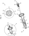
- FIG. 17 illustrates a rotor assembly 1700 for use with the power tool 100.
- the rotor assembly 1700 includes a plurality of slots 1705, and each slot 1705 is configured to receive a magnet 1710.
- the magnet 1710 may be composed of a rare earth metal, such as neodymium, and can be secured to the slot 1705, as previously described.
- the rotor assembly 1700 includes a lamination stack 1715 including a plurality of gaps 1720. In some instances, the gaps 1720 are filled with an injection molded material, such as injection molded plastic 1725, or stainless steel.
- the rotor assembly 1700 also includes a shaft 1730 extending through the rotor assembly 1700 from a first end 1735 of the rotor assembly 1700 to a second end 1740 of the rotor assembly 1700.
- a first bearing 1745 is located at the first end 1735 of the rotor assembly 1700 along with a sense magnet 1750.
- the rotor assembly 1700 also includes a fan 1755 located at the second end 1740 of the rotor assembly 1700.
- the rotor assembly 1700 further includes a second bearing 1760 located at the second end 1740 of the rotor assembly 1700, and a plurality of C-rings 1765 configured to couple the second bearing 1760 to the shaft 1730.
- a power tool comprising: a battery pack interface configured to receive a battery pack; and a motor including: a stator including a plurality of stator teeth configured to receive a plurality of stator windings, and a rotor configured to rotate with respect to the stator, the rotor including: a first permanent magnet within the rotor, a second permanent magnet within the rotor, and a consequent pole located between the first permanent magnet and the second permanent magnet, the consequent pole having a length and a width, the consequent pole being made of a non-magnetic material.
- Clause 2 The power tool of clause 1, wherein the first permanent magnet and the second permanent magnet are composed of a rare earth metal.
- the rotor includes a lamination stack including an inner lamination portion and an outer lamination portion, wherein an air gap is located between the inner lamination portion and the outer lamination portion.
- Clause 5 The power tool of clause 3, wherein the inner lamination portion includes a first axial support portion, and the outer lamination portion includes a second axial support portion.
- the rotor further includes: a lamination stack; a first slot including a first magnet housing portion configured to receive the first permanent magnet; a second slot including a second magnet housing portion configured to receive the second permanent magnet; and a plurality of air gaps, wherein each of the plurality of air gaps includes an injection molded material.
- Clause 8 The power tool of clause 7, wherein one of the plurality of air gaps is enclosed by an outer rib of the lamination stack.
- a power tool comprising: a battery pack interface configured to receive a battery pack; and a consequent pole motor including: a stator including a plurality of stator teeth configured to receive a plurality of stator windings, and a rotor configured to rotate with respect to the stator, the rotor including: a first permanent magnet within a first slot of the rotor, a second permanent magnet within a second slot of the rotor, a first consequent pole between the first permanent magnet and the second permanent magnet, the first consequent pole having a first length and a first width, and a second consequent pole between the first permanent magnet and the second permanent magnet, the second consequent pole having a second length and a second width.
- Clause 10 The power tool of clause 9, wherein the first permanent magnet and the second permanent magnet are composed of a rare earth metal.
- Clause 11 The power tool of clause 9 or 10, wherein the rotor includes a lamination stack including an inner lamination portion and an outer lamination portion, wherein an air gap is located between the inner lamination portion and the outer lamination portion, and wherein the air gap is enclosed by an outer rib of the lamination stack.
- Clause 13 The power tool of clause 11, wherein the inner lamination portion includes a first axial support portion, and the outer lamination portion includes a second axial support portion.
- Clause 14 The power tool of any of clauses 9 to 13, wherein the rotor further includes: a lamination stack; a first slot including a first magnet housing portion configured to receive the first permanent magnet; a second slot including a second magnet housing portion configured to receive the second permanent magnet; and a plurality of air gaps, wherein each of the plurality of air gaps includes an injection molded material, wherein one of the plurality of air gaps is enclosed by an outer rib of the lamination stack.
- a consequent pole motor comprising: a stator including a plurality of stator teeth configured to receive a plurality of stator windings; and a rotor configured to rotate around the stator, the rotor including: a lamination stack including an inner lamination portion and an outer lamination portion, a first permanent magnet located within a first slot of the lamination stack, the first slot being between the inner lamination portion and the outer lamination portion, a second permanent magnet located within a second slot of the lamination stack, the second slot being between the inner lamination portion and the outer lamination portion, a first consequent pole located between the first permanent magnet and the second permanent magnet, the first consequent pole having a first length and a first width, a second consequent pole located between the first permanent magnet and the second permanent magnet, the second consequent pole having a second length and a second width, and an air gap located between the inner lamination portion and the outer lamination portion.
- Clause 17 The consequent pole motor of clauses 15 or 16, wherein: the first permanent magnet and the second permanent magnet are composed of a rare earth metal; and the first consequent pole and the second consequent pole are constructed from a non-magnetic material.
- Clause 18 The consequent pole motor of any of clauses 15 to 17, wherein the air gap is enclosed by an outer rib of the lamination stack.
- Clause 20 The consequent pole motor of any of clauses 15 to 19, wherein: the rotor further includes a first retention portion configured to retain the inner lamination portion and a second retention portion configured to retain the outer lamination portion; and the first retention portion and the second retention portion are connected via a plate.
Landscapes
- Engineering & Computer Science (AREA)
- Power Engineering (AREA)
- Permanent Field Magnets Of Synchronous Machinery (AREA)
- Portable Power Tools In General (AREA)
Abstract
A power tool including a battery pack interface and a consequent pole motor. The battery pack interface is configured to receive a removable and rechargeable battery pack. The consequent pole motor includes a stator including a plurality of stator teeth configured to receive a plurality of stator coils, and a rotor configured to rotate with respect to the stator. The rotor includes a first permanent magnet positioned within the rotor, a second permanent magnet positioned within the rotor, and a consequent pole located between the first permanent magnet and the second permanent magnet. The consequent pole has a length and a width. The consequent pole is made of a non-magnetic material.
Description
- This application claims the benefit of
U.S. Provisional Patent Application No. 63/505,523, filed June 1, 2023 - Embodiments described herein relate to a motor of a power tool.
- Power tools described herein include a battery pack interface configured to receive a battery pack and a motor. The motor includes a stator including a plurality of stator teeth configured to receive a plurality of stator windings, and a rotor configured to rotate with respect to the stator. The rotor includes a first permanent magnet within the rotor, a second permanent magnet within the rotor, and a consequent pole located between the first permanent magnet and the second permanent magnet. The consequent pole has a length and a width. The consequent pole is made of a non-magnetic material.
- In some aspects, the first permanent magnet and the second permanent magnet are composed of a rare earth metal.
- In some aspects, the rotor includes a lamination stack including an inner lamination portion and an outer lamination portion, wherein an air gap is located between the inner lamination portion and the outer lamination portion.
- In some aspects, the consequent pole is constructed from the lamination stack.
- In some aspects, the inner lamination portion includes a first axial support portion, and the outer lamination portion includes a second axial support portion.
- In some aspects, the rotor includes an outer diameter of approximately 22 millimeters.
- In some aspects, the rotor further includes a lamination stack, a first slot including a first magnet housing portion configured to receive the first permanent magnet, a second slot including a second magnet housing portion configured to receive the second permanent magnet, and a plurality of air gaps, wherein each of the plurality of air gaps includes an injection molded material.
- In some aspects, one of the plurality of air gaps is enclosed by an outer rib of the lamination stack.
- Power tools described herein include a battery pack interface configured to receive a battery pack and a consequent pole motor. The consequent pole motor includes a stator including a plurality of stator teeth configured to receive a plurality of stator windings, and a rotor configured to rotate with respect to the stator. The rotor includes a first permanent magnet within a first slot of the rotor, a second permanent magnet within a second slot of the rotor, a first consequent pole between the first permanent magnet and the second permanent magnet, the first consequent pole having a first length and a first width, and a second consequent pole between the first permanent magnet and the second permanent magnet, the second consequent pole having a second length and a second width.
- In some aspects, the first permanent magnet and the second permanent magnet are composed of a rare earth metal.
- In some aspects, the rotor includes a lamination stack including an inner lamination portion and an outer lamination portion, wherein an air gap is located between the inner lamination portion and the outer lamination portion, and wherein the air gap is enclosed by an outer rib of the lamination stack.
- In some aspects, the first consequent pole and the second consequent pole are constructed from the lamination stack.
- In some aspects, the inner lamination portion includes a first axial support portion, and the outer lamination portion includes a second axial support portion.
- In some aspects, the rotor further includes a lamination stack, a first slot including a first magnet housing portion configured to receive the first permanent magnet, a second slot including a second magnet housing portion configured to receive the second permanent magnet, and a plurality of air gaps, wherein each of the plurality of air gaps includes an injection molded material, wherein one of the plurality of air gaps is enclosed by an outer rib of the lamination stack.
- Consequent pole motors described herein include a stator including a plurality of stator teeth configured to receive a plurality of stator windings, and a rotor configured to rotate around the stator. The rotor includes a lamination stack including an inner lamination portion and an outer lamination portion, a first permanent magnet located within a first slot of the lamination stack, the first slot being between the inner lamination portion and the outer lamination portion, a second permanent magnet located within a second slot of the lamination stack, the second slot being between the inner lamination portion and the outer lamination portion, a first consequent pole located between the first permanent magnet and the second permanent magnet, the first consequent pole having a first length and a first width, a second consequent pole located between the first permanent magnet and the second permanent magnet, the second consequent pole having a second length and a second width, and an air gap located between the inner lamination portion and the outer lamination portion.
- In some aspects, the first consequent pole and the second consequent pole are constructed from the lamination stack.
- In some aspects, the first permanent magnet and the second permanent magnet are composed of a rare earth metal, and the first consequent pole and the second consequent pole are constructed from a non-magnetic material.
- In some aspects, the air gap is enclosed by an outer rib of the lamination stack.
- In some aspects, the air gap is filled with an injection molded material.
- In some aspects, the rotor further includes a first retention portion configured to retain the inner lamination portion and a second retention portion configured to retain the outer lamination portion, and the first retention portion and the second retention portion are connected via a plate.
- Before any embodiments are explained in detail, it is to be understood that the embodiments are not limited in application to the details of the configurations and arrangements of components set forth in the following description or illustrated in the accompanying drawings. The embodiments are capable of being practiced or of being carried out in various ways. Also, it is to be understood that the phraseology and terminology used herein are for the purpose of description and should not be regarded as limiting. The use of "including," "comprising," or "having" and variations thereof are meant to encompass the items listed thereafter and equivalents thereof as well as additional items. Unless specified or limited otherwise, the terms "mounted," "connected," "supported," and "coupled" and variations thereof are used broadly and encompass both direct and indirect mountings, connections, supports, and couplings.
- Unless the context of their usage unambiguously indicates otherwise, the articles "a," "an," and "the" should not be interpreted as meaning "one" or "only one." Rather these articles should be interpreted as meaning "at least one" or "one or more." Likewise, when the terms "the" or "said" are used to refer to a noun previously introduced by the indefinite article "a" or "an," "the" and "said" mean "at least one" or "one or more" unless the usage unambiguously indicates otherwise.
- In addition, it should be understood that embodiments may include hardware, software, and electronic components or modules that, for purposes of discussion, may be illustrated and described as if the majority of the components were implemented solely in hardware. However, one of ordinary skill in the art, and based on a reading of this detailed description, would recognize that, in at least one embodiment, the electronic-based aspects may be implemented in software (e.g., stored on non-transitory computer-readable medium) executable by one or more processing units, such as a microprocessor and/or application specific integrated circuits ("ASICs"). As such, it should be noted that a plurality of hardware and software based devices, as well as a plurality of different structural components, may be utilized to implement the embodiments. For example, "servers," "computing devices," "controllers," "processors," etc., described in the specification can include one or more processing units, one or more computer-readable medium modules, one or more input/output interfaces, and various connections (e.g., a system bus) connecting the components.
- Relative terminology, such as, for example, "about," "approximately," "substantially," etc., used in connection with a quantity or condition would be understood by those of ordinary skill to be inclusive of the stated value and has the meaning dictated by the context (e.g., the term includes at least the degree of error associated with the measurement accuracy, tolerances [e.g., manufacturing, assembly, use, etc.] associated with the particular value, etc.). Such terminology should also be considered as disclosing the range defined by the absolute values of the two endpoints. For example, the expression "from about 2 to about 4" also discloses the range "from 2 to 4". The relative terminology may refer to plus or minus a percentage (e.g., 1%, 5%, 10%) of an indicated value.
- It should be understood that although certain drawings illustrate hardware and software located within particular devices, these depictions are for illustrative purposes only. Functionality described herein as being performed by one component may be performed by multiple components in a distributed manner. Likewise, functionality performed by multiple components may be consolidated and performed by a single component. In some embodiments, the illustrated components may be combined or divided into separate software, firmware and/or hardware. For example, instead of being located within and performed by a single electronic processor, logic and processing may be distributed among multiple electronic processors. Regardless of how they are combined or divided, hardware and software components may be located on the same computing device or may be distributed among different computing devices connected by one or more networks or other suitable communication links. Similarly, a component described as performing particular functionality may also perform additional functionality not described herein. For example, a device or structure that is "configured" in a certain way is configured in at least that way but may also be configured in ways that are not explicitly listed.
- Accordingly, in the claims, if an apparatus, method, or system is claimed, for example, as including a controller, control unit, electronic processor, computing device, logic element, module, memory module, communication channel or network, or other element configured in a certain manner, for example, to perform multiple functions, the claim or claim element should be interpreted as meaning one or more of such elements where any one of the one or more elements is configured as claimed, for example, to make any one or more of the recited multiple functions, such that the one or more elements, as a set, perform the multiple functions collectively.
- Other aspects of the embodiments will become apparent by consideration of the detailed description and accompanying drawings.
-
-
FIG. 1 illustrates a perspective view of a power tool, according to some embodiments. -
FIG. 2 illustrates a block diagram of a control system of the power tool ofFIG. 1 , according to some embodiments. -
FIG. 3 illustrates a battery pack for use with the power tool ofFIG. 1 , according to some embodiments. -
FIG. 4 illustrates a block diagram of a control system of the battery pack ofFIG. 3 , according to some embodiments. -
FIG. 5 illustrates an internal permanent magnet motor rotor, according to some embodiments. -
FIG. 6A illustrates an internal permanent magnet motor, according to some embodiments. -
FIG. 6B illustrates an internal permanent magnet motor, according to some embodiments. -
FIG. 6C illustrates an internal permanent magnet motor, according to some embodiments. -
FIG. 6D illustrates an internal permanent magnet motor, according to some embodiments. -
FIG. 7 illustrates a consequent pole motor, according to some embodiments. -
FIG. 8 graphically illustrates performance of various motors, according to some embodiments. -
FIG. 9 illustrates a consequent pole motor, according to some embodiments. -
FIG. 10 graphically illustrates performance of various motors, according to some embodiments. -
FIG. 11 illustrates an internal permanent magnet motor, according to some embodiments. -
FIG. 12 graphically illustrates performance of various motors, according to some embodiments. -
FIG. 13 illustrates a permanent magnet motor, according to some embodiments. -
FIG. 14 illustrates a permanent magnet motor, according to some embodiments. -
FIG. 15 illustrates a permanent magnet motor, according to some embodiments. -
FIG. 16 graphically illustrates performance of various motors, according to some embodiments. -
FIG. 17 illustrates a permanent magnet motor, according to some embodiments. -
FIG. 1 illustrates apower tool 100 including a permanent magnet motor. Thepower tool 100 is, for example, a hammer drill including ahousing 102. Thehousing 102 includes ahandle portion 104 andmotor housing portion 106. Thepower tool 100 further includes an output driver 108 (illustrated as a chuck), atrigger 110, and abattery pack interface 112. Thebattery pack interface 112 is configured to mechanically and electrically connect to or receive a power tool battery pack. AlthoughFIG. 1 illustrates a hammer drill, in some embodiments, the components described herein are incorporated into other types of power tools including drill-drivers, impact drivers, impact wrenches, angle grinders, circular saws, reciprocating saws, plate compactors, core drills, string trimmers, leaf blowers, vacuums, and the like. In a permanent magnet motor power tool, such aspower tool 100, switching elements are selectively enabled and disabled by control signals from a controller to selectively apply power from a power source (e.g., a battery pack) to drive a permanent magnet motor. -
FIG. 2 illustrates acontrol system 200 for thepower tool 100. Thecontrol system 200 includes acontroller 202. Thecontroller 202 is electrically and/or communicatively connected to a variety of modules or components of thepower tool 100. For example, the illustratedcontroller 202 is electrically connected to amotor 204, abattery pack interface 206, a trigger switch 208 (connected to a trigger 210), one or more sensors orsensing circuits 212, one ormore indicators 214, auser input module 216, apower input module 218, an inverter bridge or FET switching module 220 (e.g., including a plurality of switching FETs), andgate drivers 224 for driving theFET switching module 220. In some embodiments,motor 204 is a permanent magnet motor. Thecontroller 202 includes combinations of hardware and software that are operable to, among other things, control the operation of thepower tool 100, monitor the operation of thepower tool 100, activate the one or more indicators 214 (e.g., an LED), etc. - The
controller 202 includes a plurality of electrical and electronic components that provide power, operational control, and protection to the components and modules within thecontroller 202 and/or thepower tool 100. For example, thecontroller 202 includes, among other things, a processing unit 226 (e.g., a microprocessor, a microcontroller, an electronic controller, an electronic processor, or another suitable programmable device), amemory 228,input units 230, andoutput units 232. Theprocessing unit 226 includes, among other things, acontrol unit 234, an arithmetic logic unit ("ALU") 236, and a plurality ofregisters 238, and is implemented using a known computer architecture (e.g., a modified Harvard architecture, a von Neumann architecture, etc.). Theprocessing unit 226, thememory 228, theinput units 230, and theoutput units 232, as well as the various modules or circuits connected to thecontroller 202 are connected by one or more control and/or data buses (e.g., common bus 240). The control and/or data buses are shown generally inFIG. 2 for illustrative purposes. The use of one or more control and/or data buses for the interconnection between and communication among the various modules, circuits, and components would be known to a person skilled in the art in view of the embodiments described herein. - The
memory 228 is a non-transitory computer readable medium and includes, for example, a program storage area and a data storage area. The program storage area and the data storage area can include combinations of different types of memory, such as a ROM, a RAM (e.g., DRAM, SDRAM, etc.), EEPROM, flash memory, a hard disk, an SD card, or other suitable magnetic, optical, physical, or electronic memory devices. Theprocessing unit 226 is connected to thememory 228 and executes software instructions that are capable of being stored in a RAM of the memory 228 (e.g., during execution), a ROM of the memory 228 (e.g., on a generally permanent basis), or another non-transitory computer readable medium such as another memory or a disc. Software included in the implementation of thepower tool 100 can be stored in thememory 228 of thecontroller 202. The software includes, for example, firmware, one or more applications, program data, filters, rules, one or more program modules, and other executable instructions. Thecontroller 202 is configured to retrieve from thememory 228 and execute, among other things, instructions related to the control processes and methods described herein. In other constructions, thecontroller 202 includes additional, fewer, or different components. - The
battery pack interface 206 includes a combination of mechanical components (e.g., rails, grooves, latches, etc.) and electrical components (e.g., one or more terminals) configured to and operable for interfacing (e.g., mechanically, electrically, and communicatively connecting) with a battery pack. For example, power provided by a battery pack 300 (seeFIG. 3 ) to thepower tool 100 is provided through thebattery pack interface 206 to thepower input module 218. Thepower input module 218 includes combinations of active and passive components to regulate or control the power received from thebattery pack 300 prior to power being provided to thecontroller 202. Thebattery pack interface 206 also supplies power to theFET switching module 220 to be switched by the switching FETs to selectively provide power to themotor 204. Thebattery pack interface 206 also includes, for example, acommunication line 242 for providing a communication line or link between thecontroller 202 and thebattery pack 300. - The
sensor circuits 212 include one or more current sensors, one or more speed sensors, one or more Hall effect sensors, one or more temperature sensors, etc. Theindicators 214 include, for example, one or more light-emitting diodes ("LEDs"). Theindicators 214 can be configured to display conditions of, or information associated with, thepower tool 100. For example, theindicators 214 are configured to indicate measured electrical characteristics of thepower tool 100, the status of the power tool, the status themotor 204, etc. Theuser input module 216 is operably coupled to thecontroller 202 to, for example, select a forward mode of operation or a reverse mode of operation, a torque and/or speed setting for the power tool 100 (e.g., using torque and/or speed switches), etc. In some embodiments, theuser input module 216 includes a combination of digital and analog input or output devices required to achieve a desired level of operation for thepower tool 100, such as one or more knobs, one or more dials, one or more switches, one or more buttons, etc. -
FIG. 3 illustrates abattery pack 300. Thebattery pack 300 includes ahousing 302 and aninterface portion 304 for connecting thebattery pack 300 to a power tool, such as thepower tool 100. -
FIG. 4 illustrates a control system for thebattery pack 300. The control system includes acontroller 400. Thecontroller 400 is electrically and/or communicatively connected to a variety of modules or components of thebattery pack 300. For example, the illustratedcontroller 400 is connected to one ormore battery cells 402 and an interface 404 (e.g., theinterface portion 304 of thebattery pack 300 illustrated inFIG. 3 ). Thecontroller 400 is also connected to one or more voltage sensors orvoltage sensing circuits 406, one or more current sensors orcurrent sensing circuits 408, and one or more temperature sensors ortemperature sensing circuits 410. Thecontroller 400 includes combinations of hardware and software that are operable to, among other things, control the operation of thebattery pack 300, monitor a condition of thebattery pack 300, enable or disable charging of thebattery pack 300, enable or disable discharging of thebattery pack 300, etc. - The
controller 400 includes a plurality of electrical and electronic components that provide power, operational control, and protection to the components and modules within thecontroller 400 and/or thebattery pack 300. For example, thecontroller 400 includes, among other things, a processing unit 412 (e.g., a microprocessor, a microcontroller, an electronic processor, an electronic controller, or another suitable programmable device), amemory 414,input units 416, andoutput units 418. Theprocessing unit 412 includes, among other things, acontrol unit 420, anALU 422, and a plurality ofregisters 424, and is implemented using a known computer architecture (e.g., a modified Harvard architecture, a von Neumann architecture, etc.). Theprocessing unit 412, thememory 414, theinput units 416, and theoutput units 418, as well as the various modules or circuits connected to thecontroller 400 are connected by one or more control and/or data buses (e.g., common bus 426). The control and/or data buses are shown generally inFIG. 4 for illustrative purposes. The use of one or more control and/or data buses for the interconnection between and communication among the various modules, circuits, and components would be known to a person skilled in the art in view of the embodiments described herein. - The
memory 414 is a non-transitory computer readable medium and includes, for example, a program storage area and a data storage area. The program storage area and the data storage area can include combinations of different types of memory, such as a ROM, a RAM (e.g., DRAM, SDRAM, etc.), EEPROM, flash memory, a hard disk, an SD card, or other suitable magnetic, optical, physical, or electronic memory devices. Theprocessing unit 412 is connected to thememory 414 and executes software instructions that are capable of being stored in a RAM of the memory 414 (e.g., during execution), a ROM of the memory 414 (e.g., on a generally permanent basis), or another non-transitory computer readable medium such as another memory or a disc. Software included in the implementation of thebattery pack 300 can be stored in thememory 414 of thecontroller 400. The software includes, for example, firmware, one or more applications, program data, filters, rules, one or more program modules, and other executable instructions. Thecontroller 400 is configured to retrieve from thememory 414 and execute, among other things, instructions related to the control processes and methods described herein. In other constructions, thecontroller 400 includes additional, fewer, or different components. - The
interface 404 includes a combination of mechanical components (e.g., rails, grooves, latches, etc.) and electrical components (e.g., one or more terminals) configured to and operable for interfacing (e.g., mechanically, electrically, and communicatively connecting) thebattery pack 300 with another device (e.g., a power tool, a battery pack charger, etc.). For example, theinterface 404 is configured to communicatively connect to thecontroller 400 via acommunications line 428. -
FIG. 5 illustrates an internal permanentmagnet motor rotor 500, according to some embodiments. Therotor 500 includes alamination stack 505. Thelamination stack 505 includes aninner lamination portion 510 and anouter lamination portion 515. Therotor 500 includes a plurality ofslots 520, and each slot includes amagnet housing portion 525 configured to receive amagnet 530. Themagnet 530 includes alength 535 and awidth 540. Therotor 500 also includes arotor sleeve 545. In some embodiments, therotor sleeve 545 is made of a carbon fiber material. In some embodiments, the carbon fiber sleeve is made of another material, such as a plastic, a non-magnetic metal, a polycarbonate, or the like. Therotor 500 is configured to rotate with respect to a stator. -
FIG. 6A-6D illustrate internal permanentmagnet motor rotors FIG. 6A , therotor 600A includes alamination stack 605. Thelamination stack 605 includes aninner lamination portion 610 and anouter lamination portion 615. Therotor 600A includes a plurality ofslots 620, and eachslot 620 includes amagnet housing portion 625 configured to receive amagnet 630. Themagnet 630 includes alength 635 and awidth 640. Theinner lamination portion 610 of thelamination stack 605 includes a firstaxial support portion 645. Theouter lamination portion 615 of thelamination stack 605 includes a secondaxial support portion 650. In some embodiments, aplastic mold 655 is configured to retain theinner lamination portion 610 and theouter lamination portion 615 of thelamination stack 605. Theplastic mold 655 may include afirst retention portion 660 configured to retain theplastic mold 655 to theinner lamination portion 610, and asecond retention portion 665 configured to retain the plastic mold to theouter lamination portion 615. Theplastic mold 655 also includes aplate 670 configured to connect thefirst retention portion 660 and thesecond retention portion 665 to each other, thereby creating a single secure element for retaining theinner lamination portion 610, theouter lamination portion 615, and themagnets 630. Therotor 600A is configured to rotate with respect to a stator. -
FIG. 6B illustrates the permanentmagnet motor rotor 600B. In this embodiment, therotor 600B includes the firstaxial support portion 645, thefirst retention portion 660, thesecond retention portion 665 and theplate 670 made of injection molded plastic, and the secondaxial support portion 650 and aplate portion 675 made of stainless-steel. The stainless-steel plate portion 675 is configured to connect to the secondaxial support portion 650. Therotor 600B is configured to rotate with respect to a stator. -
FIG 6C illustrates another embodiment for therotor 600C. In this embodiment, both the firstaxial support portion 645 and the secondaxial support portion 650 are made of stainless-steel, and are configured to connect to the stainless-steel plate portion 675. Therotor 600C is configured to rotate with respect to a stator. -
FIG 6D illustrates another embodiment for therotor 600D. In this embodiment, an inneradhesive layer 680 and an outeradhesive layer 685 are used to hold themagnets 630 and thelamination stack 605 together. The adhesive used in the inner and outer adhesive layers (680, 685) may be an epoxy, a structural acrylic, cyanoacrylate, or other type of bonding material. In some instances, a Teflon mold may be used during the assembly process. Therotor 600D is configured to rotate with respect to a stator. -
FIG. 7 illustrates aconsequent pole motor 700, according to some embodiments. Themotor 700 includes astator 705 and a plurality ofstator winding slots 710. The stator also includesstator teeth 713. The plurality ofstator winding slots 710 are configured to receive a plurality of windings, wound around thestator teeth 713. Themotor 700 also includes arotor 715. Therotor 715 includes a plurality ofpermanent magnet slots 720 configured to receivepermanent magnets 725. Therotor 715 includes a plurality ofconsequent poles 730. Theconsequent poles 730 have a length 735 and awidth 740. In some embodiments, each of the consequent poles includes the same length and width. In other embodiments, the consequent poles have different lengths and widths. In some embodiments, the length 735 or thewidth 740 of theconsequent pole 730 is controlled to impact the performance of themotor 700. The impacts of the dimensions of theconsequent pole 730 are illustrated inFIG. 8 and described in detail below. Themotor 700 also includes anair gap 745 between the plurality ofpermanent magnets 725 and theconsequent poles 730. In some embodiments, theair gaps 745 are enclosed by anouter rib 750 of thelamination stack 755. In some embodiments, theair gaps 745 are ribless. In some embodiments, theconsequent poles 730 are made of a non-magnetic material (e.g., rotor laminations, etc.). In some embodiments, theconsequent pole motor 700 can include any of the motor rotor features described above with respect toFIGS. 5 ,6A ,6B ,6C , and6D . Therotor 715 is configured to rotate with respect to a stator. -
FIG. 8 graphically illustrates the performance of an internal permanent magnet ("IPM") motor compared to theconsequent pole motor 700, according to some embodiments. The graph includesIPM motor efficiency 805, IPMmotor output power 815, IPM motor current 825, andIPM motor speed 835 when compared to a motor torque. The graph also includes consequentpole motor efficiency 810, consequent polemotor output power 820, consequent pole motor current 830, and consequentpole motor speed 840 when compared to a motor torque. Thegraph 800 also includes a highlightedoperating region 845, within which both the IPM motor and themotor 700 nominally operate. As evidenced by thegraph 800, the performance for both IPM motor and themotor 700 are similar within theoperating region 845. In some examples, the IPM motor represented on thegraph 800 has a magnet mass of approximately 55g, while themotor 700 has approximately a 28% mass reduction without significantly impacting the performance of themotor 700 within theoperating region 845. -
FIG. 9 illustrates aconsequent pole motor 900, according to some embodiments. Themotor 900 includes astator 905 and a plurality ofstator winding slots 910. The stator also includesstator teeth 913. The plurality ofstator winding slots 910 are configured to receive a plurality of windings, wound around thestator teeth 913. Thestator 905 includesair gaps 914 between the plurality ofstator winding slots 910. Themotor 900 also includes arotor 915. Therotor 915 includes a plurality ofpermanent magnet slots 920 configured to receivepermanent magnets 925. Therotor 915 includes a plurality ofconsequent poles 930. Theconsequent poles 930 have alength 935 and awidth 940. In some embodiments, each of the consequent poles includes the same length and width. In other embodiments, the consequent poles have different lengths and widths. In some embodiments, thelength 935 or thewidth 940 of theconsequent pole 930 are controlled to impact the performance of themotor 900. The impacts of the dimensions of theconsequent pole 930 are illustrated inFIG. 10 and described in detail below. Themotor 900 also includesair gaps 945 between the plurality ofmagnets 925 and theconsequent poles 930. In some embodiments, theair gaps 945 are enclosed by anouter rib 950 of thelamination stack 955. In some embodiments, theair gaps 945 are ribless. In some embodiments, theconsequent poles 930 are made of a non-magnetic material (e.g., rotor laminations, etc.). In some embodiments, theconsequent pole motor 900 can include any of the motor rotor features described above with respect toFIGS. 5 ,6A ,6B ,6C , and6D . Therotor 915 is configured to rotate with respect to a stator. -
FIG. 10 provides agraph 1000 that illustrates a performance comparison between an internal permanent magnet motor and themotor 900. The graph includesIPM motor efficiency 1005, IPMmotor output power 1015, IPM motor current 1025, andIPM motor speed 1035 when compared to a motor torque. The graph also includes consequentpole motor efficiency 1010, consequent polemotor output power 1020, consequent pole motor current 1030, and consequentpole motor speed 1040 when compared to a motor torque. Thegraph 1000 also includes a target operating load 1045 of approximately 0.19Nm, and atarget operating speed 1050 of approximately 42,000 RPM. As evidenced by thegraph 1000, at higher torque levels, the IPM motor performs with agreater efficiency 1005 andoutput power 1015 than themotor 900efficiency 1010 andoutput power 1020. However, the performance for both IPM motor and themotor 900 are similar within the target operating load 1045 region. In some examples, the IPM motor represented on thegraph 1000 has a magnet mass of approximately 79g, while themotor 900 has approximately a 36% mass reduction without significantly impacting the performance of themotor 900 within the target operating load 1045 region. -
FIG. 11 illustrates an internalpermanent magnet motor 1100, according to some embodiments. Themotor 1100 includes astator 1105 and a plurality ofstator winding slots 1110. Thestator 1105 also includesstator teeth 1113. The plurality ofstator winding slots 1110 are configured to receive a plurality of windings, wound around thestator teeth 1113. Themotor 1100 also includes arotor 1115. Therotor 1115 includes a plurality ofslots 1120, and eachslot 1120 includes amagnet housing portion 1125 configured to receive amagnet 1130. Themagnets 1130 include alength 1135 and awidth 1140. Therotor 1115 further includes alamination stack 1145 including an inner lamination portion 1150 and anouter lamination portion 1155. The inner lamination portion 1150 of thelamination stack 1145 includes a firstaxial support portion 1160. Theouter lamination portion 1155 of thelamination stack 1145 includes a secondaxial support portion 1165. In some embodiments, a plastic mold is configured to retain the inner lamination portion and the outer lamination portion as previously described, and as illustrated inFIGS. 6A-6D . Themotor 1100 does not include outer steel ribs that would otherwise enclose themagnets 1130. -
FIG. 12 is agraph 1200 that illustrates a performance comparison between a conventional internal permanent magnet motor and themotor 1100. Thegraph 1200 includes conventionalIPM motor efficiency 1205, conventional IPMmotor output power 1215, conventional IPM motor current 1225, and conventionalIPM motor speed 1235 when compared to a motor torque. Thegraph 1200 also includesmotor efficiency 1210,output power 1220, motor current 1230, andmotor speed 1240 for themotor 1100 when compared to a motor torque. As evidenced by thegraph 1200 the conventional IPM motor performs with approximately thesame efficiency 1205 as themotor 1100efficiency 1210. However, themotor 1100 produces, for example, approximately 5% more power than the conventional IPM motor. -
FIG. 13 illustrates a permanent magnet motor, according to some embodiments. In some embodiments, themotor 1300 is configured for use in thepower tool 100. Themotor 1300 includes an internal permanent magnet configuration. Themotor 1300 includes astator 1305 and a plurality ofstator winding slots 1310. The plurality ofstator winding slots 1310 are configured to receive a plurality of windings. Themotor 1300 also includes arotor 1315. In some embodiments, the rotor has an outer diameter of 22 millimeters ("mm"). Therotor 1315 includes a plurality ofslots 1320, and each slot includes amagnet housing portion 1325 configured to receive amagnet 1330. Themagnet 1330 includes alength 1335 and awidth 1340. Therotor 1315 further includes a lamination stack 1345 andair gaps 1350. Theair gaps 1350 include alength 1355 and awidth 1360. In some embodiments, the size of theair gaps 1350, or thelength 1355 andwidth 1360 of theair gaps 1350, increases or decreases along with the size of themagnet 1330. For example, thelength 1335 of themagnet 1330 may be decreased in order to reduce the manufacturing cost of themotor 1300. Accordingly, thelength 1355 of the air gap may be increased along with the reducedmagnet 1330 size. Alternatively, in some embodiments, the lamination stack 1345 is configured to occupy the space of the reducedmagnet 1330length 1335. -
FIG. 14 illustrates a permanent magnet motor, according to some embodiments. Themotor 1400 includes astator 1405 and a plurality ofstator winding slots 1410. The stator also includes stator teeth 1413. The plurality ofstator winding slots 1410 are configured to receive a plurality of windings, wound around the stator teeth 1413. Themotor 1400 also includes arotor 1415. Therotor 1415 includes a plurality ofslots 1420, and each slot includes amagnet housing portion 1425 configured to receive amagnet 1430. Themagnets 1430 includes alength 1435 and awidth 1440. The rotor further includes alamination stack 1445 including an inner lamination portion 1450 and anouter lamination portion 1455. The inner lamination portion 1450 of thelamination stack 1445 includes a firstaxial support portion 1460. In some embodiments, themotor 1400 is similar to themotor 1100. -
FIG. 15 illustrates an internal permanent magnet motor, according to some embodiments. Themotor 1500 includes astator 1505 and a plurality ofstator winding slots 1510. The stator also includesstator teeth 1513. The plurality ofstator winding slots 1510 are configured to receive a plurality of windings, wound around thestator teeth 1513. Themotor 1500 also includes arotor 1515. Therotor 1515 includes a plurality of slots 1520, and each slot includes amagnet housing portion 1525 configured to receive amagnet 1530. Themagnets 1530 includes alength 1535 and awidth 1540. The rotor further includes a lamination stack 1545 including aninner lamination portion 1550 and anouter lamination portion 1555. Theinner lamination portion 1550 of the lamination stack 1545 includes a firstaxial support portion 1560. Theouter lamination portion 1555 of the lamination stack 1545 includes a secondaxial support portion 1565. In some embodiments, a plastic mold is configured to retain the inner lamination portion and the outer lamination portion as previously described, and as illustrated inFIGS. 6A-6D . -
FIG. 16 provides agraph 1600 that illustrates a performance comparison between themotors efficiency 1605,output power 1620, current 1635, andspeed 1650 ofmotor 1300 when compared to a motor torque. The graph includesefficiency 1610,output power 1625, current 1640, andspeed 1655 ofmotor 1400 when compared to a motor torque. The graph also includesefficiency 1615,output power 1630, current 1645, andspeed 1660 ofmotor 1500 when compared to a motor torque. Thegraph 1600 also includes atarget operating region 1665 that spans from approximately 0.5Nm to 3.9Nm of motor torque. As evidenced by thegraph 1600, at higher torque levels, themotor 1400 performs with agreater efficiency 1610 andoutput power 1625 than themotor 1300efficiency 1605 andoutput power 1620, as well as themotor 1500efficiency 1615 andoutput power 1630. Table 1 additionally illustrates comparisons between themotors motor 1400 performs at a 6% greater Watt Newton meter (WNm) and a 7% greater peak power (W) than themotor 1300, while having approximately the same efficiency and magnet mass. On the other hand, themotor 1500 achieves a 1% greater WNm with a -1% lower peak power while having a 35% reduction in magnet mass.Table 1: Performance Comparison Motor 1300 Motor 1400Motor 1500Peak WNm (power area) 7,488 WNm +6% +1% Peak Power 3,180 W +7% -1% Average Efficiency (power area) 69.8% 0% -1% Peak Efficiency 89% 0% 0% Magnet Mass 55g 0% -35% -
FIG. 17 illustrates arotor assembly 1700 for use with thepower tool 100. Therotor assembly 1700 includes a plurality ofslots 1705, and eachslot 1705 is configured to receive amagnet 1710. Themagnet 1710 may be composed of a rare earth metal, such as neodymium, and can be secured to theslot 1705, as previously described. Therotor assembly 1700 includes alamination stack 1715 including a plurality ofgaps 1720. In some instances, thegaps 1720 are filled with an injection molded material, such as injection molded plastic 1725, or stainless steel. Therotor assembly 1700 also includes ashaft 1730 extending through therotor assembly 1700 from afirst end 1735 of therotor assembly 1700 to asecond end 1740 of therotor assembly 1700. Afirst bearing 1745 is located at thefirst end 1735 of therotor assembly 1700 along with asense magnet 1750. Therotor assembly 1700 also includes afan 1755 located at thesecond end 1740 of therotor assembly 1700. Therotor assembly 1700 further includes asecond bearing 1760 located at thesecond end 1740 of therotor assembly 1700, and a plurality of C-rings 1765 configured to couple thesecond bearing 1760 to theshaft 1730. - Representative features are set out in the following clauses, which stand alone or may be combined, in any combination, with one or more features disclosed in the text and/or drawings of the specification.
- Clause 1. A power tool comprising: a battery pack interface configured to receive a battery pack; and a motor including: a stator including a plurality of stator teeth configured to receive a plurality of stator windings, and a rotor configured to rotate with respect to the stator, the rotor including: a first permanent magnet within the rotor, a second permanent magnet within the rotor, and a consequent pole located between the first permanent magnet and the second permanent magnet, the consequent pole having a length and a width, the consequent pole being made of a non-magnetic material.
- Clause 2. The power tool of clause 1, wherein the first permanent magnet and the second permanent magnet are composed of a rare earth metal.
-
Clause 3. The power tool of any preceding clause, wherein the rotor includes a lamination stack including an inner lamination portion and an outer lamination portion, wherein an air gap is located between the inner lamination portion and the outer lamination portion. - Clause 4. The power tool of
clause 3, wherein the consequent pole is constructed from the lamination stack. -
Clause 5. The power tool ofclause 3, wherein the inner lamination portion includes a first axial support portion, and the outer lamination portion includes a second axial support portion. - Clause 6. The power tool of
clause 3, rotor includes an outer diameter of approximately 22 millimeters. - Clause 7. The power tool of any preceding clause, wherein the rotor further includes: a lamination stack; a first slot including a first magnet housing portion configured to receive the first permanent magnet; a second slot including a second magnet housing portion configured to receive the second permanent magnet; and a plurality of air gaps, wherein each of the plurality of air gaps includes an injection molded material.
-
Clause 8. The power tool of clause 7, wherein one of the plurality of air gaps is enclosed by an outer rib of the lamination stack. -
Clause 9. A power tool comprising: a battery pack interface configured to receive a battery pack; and a consequent pole motor including: a stator including a plurality of stator teeth configured to receive a plurality of stator windings, and a rotor configured to rotate with respect to the stator, the rotor including: a first permanent magnet within a first slot of the rotor, a second permanent magnet within a second slot of the rotor, a first consequent pole between the first permanent magnet and the second permanent magnet, the first consequent pole having a first length and a first width, and a second consequent pole between the first permanent magnet and the second permanent magnet, the second consequent pole having a second length and a second width. -
Clause 10. The power tool ofclause 9, wherein the first permanent magnet and the second permanent magnet are composed of a rare earth metal. - Clause 11. The power tool of
clause - Clause 12. The power tool of clause 11, wherein the first consequent pole and the second consequent pole are constructed from the lamination stack.
- Clause 13. The power tool of clause 11, wherein the inner lamination portion includes a first axial support portion, and the outer lamination portion includes a second axial support portion.
- Clause 14. The power tool of any of
clauses 9 to 13, wherein the rotor further includes: a lamination stack; a first slot including a first magnet housing portion configured to receive the first permanent magnet; a second slot including a second magnet housing portion configured to receive the second permanent magnet; and a plurality of air gaps, wherein each of the plurality of air gaps includes an injection molded material, wherein one of the plurality of air gaps is enclosed by an outer rib of the lamination stack. - Clause 15. A consequent pole motor comprising: a stator including a plurality of stator teeth configured to receive a plurality of stator windings; and a rotor configured to rotate around the stator, the rotor including: a lamination stack including an inner lamination portion and an outer lamination portion, a first permanent magnet located within a first slot of the lamination stack, the first slot being between the inner lamination portion and the outer lamination portion, a second permanent magnet located within a second slot of the lamination stack, the second slot being between the inner lamination portion and the outer lamination portion, a first consequent pole located between the first permanent magnet and the second permanent magnet, the first consequent pole having a first length and a first width, a second consequent pole located between the first permanent magnet and the second permanent magnet, the second consequent pole having a second length and a second width, and an air gap located between the inner lamination portion and the outer lamination portion.
- Clause 16. The consequent pole motor of clause 15, wherein the first consequent pole and the second consequent pole are constructed from the lamination stack.
- Clause 17. The consequent pole motor of clauses 15 or 16, wherein: the first permanent magnet and the second permanent magnet are composed of a rare earth metal; and the first consequent pole and the second consequent pole are constructed from a non-magnetic material.
- Clause 18. The consequent pole motor of any of clauses 15 to 17, wherein the air gap is enclosed by an outer rib of the lamination stack.
- Clause 19. The consequent pole motor of any of clauses 15 to 18, wherein the air gap is filled with an injection molded material.
-
Clause 20. The consequent pole motor of any of clauses 15 to 19, wherein: the rotor further includes a first retention portion configured to retain the inner lamination portion and a second retention portion configured to retain the outer lamination portion; and the first retention portion and the second retention portion are connected via a plate. - Thus, embodiments described herein provide a power tool including a consequent pole motor. Various features and advantages are set forth in the following claims.
Claims (14)
- A power tool comprising:a battery pack interface configured to receive a battery pack; anda motor including:a stator including a plurality of stator teeth configured to receive a plurality of stator windings, anda rotor configured to rotate with respect to the stator, the rotor including:a first permanent magnet within the rotor,a second permanent magnet within the rotor, anda consequent pole located between the first permanent magnet and the second permanent magnet, the consequent pole having a length and a width, the consequent pole being made of a non-magnetic material.
- The power tool of claim 1, wherein the first permanent magnet and the second permanent magnet are composed of a rare earth metal.
- The power tool of claim 1, wherein the rotor includes a lamination stack including an inner lamination portion and an outer lamination portion, wherein an air gap is located between the inner lamination portion and the outer lamination portion.
- The power tool of claim 3, wherein the consequent pole is constructed from the lamination stack.
- The power tool of claim 3, wherein the inner lamination portion includes a first axial support portion, and the outer lamination portion includes a second axial support portion.
- The power tool of claim 3, rotor includes an outer diameter of approximately 22 millimeters.
- The power tool of claim 1, wherein the rotor further includes:a lamination stack;a first slot including a first magnet housing portion configured to receive the first permanent magnet;a second slot including a second magnet housing portion configured to receive the second permanent magnet; anda plurality of air gaps, wherein each of the plurality of air gaps includes an injection molded material.
- The power tool of claim 7, wherein one of the plurality of air gaps is enclosed by an outer rib of the lamination stack.
- A consequent pole motor comprising:a stator including a plurality of stator teeth configured to receive a plurality of stator windings; anda rotor configured to rotate around the stator, the rotor including:a lamination stack including an inner lamination portion and an outer lamination portion,a first permanent magnet located within a first slot of the lamination stack, the first slot being between the inner lamination portion and the outer lamination portion,a second permanent magnet located within a second slot of the lamination stack, the second slot being between the inner lamination portion and the outer lamination portion,a first consequent pole located between the first permanent magnet and the second permanent magnet, the first consequent pole having a first length and a first width,a second consequent pole located between the first permanent magnet and the second permanent magnet, the second consequent pole having a second length and a second width, andan air gap located between the inner lamination portion and the outer lamination portion.
- The consequent pole motor of claim 9, wherein the first consequent pole and the second consequent pole are constructed from the lamination stack.
- The consequent pole motor of claim 9, wherein:the first permanent magnet and the second permanent magnet are composed of a rare earth metal; andthe first consequent pole and the second consequent pole are constructed from a non-magnetic material.
- The consequent pole motor of claim 9, wherein the air gap is enclosed by an outer rib of the lamination stack.
- The consequent pole motor of claim 9, wherein the air gap is filled with an injection molded material.
- The consequent pole motor of claim 9, wherein:the rotor further includes a first retention portion configured to retain the inner lamination portion and a second retention portion configured to retain the outer lamination portion; andthe first retention portion and the second retention portion are connected via a plate.
Applications Claiming Priority (1)
| Application Number | Priority Date | Filing Date | Title |
|---|---|---|---|
| US202363505523P | 2023-06-01 | 2023-06-01 |
Publications (1)
| Publication Number | Publication Date |
|---|---|
| EP4475394A1 true EP4475394A1 (en) | 2024-12-11 |
Family
ID=91375289
Family Applications (1)
| Application Number | Title | Priority Date | Filing Date |
|---|---|---|---|
| EP24179270.4A Pending EP4475394A1 (en) | 2023-06-01 | 2024-05-31 | Power tool motor rotor configurations |
Country Status (4)
| Country | Link |
|---|---|
| US (1) | US20240405621A1 (en) |
| EP (1) | EP4475394A1 (en) |
| JP (1) | JP7830547B2 (en) |
| CN (1) | CN119070512A (en) |
Citations (5)
| Publication number | Priority date | Publication date | Assignee | Title |
|---|---|---|---|---|
| US20090295248A1 (en) * | 2008-05-30 | 2009-12-03 | Li Yongbin | Electric motor |
| US20120098378A1 (en) * | 2010-10-25 | 2012-04-26 | Asmo Co, Ltd. | Motor |
| CN207504658U (en) * | 2017-12-06 | 2018-06-15 | 珠海格力电器股份有限公司 | Alternating-pole motor and compressor with same |
| US20210242731A1 (en) * | 2020-02-05 | 2021-08-05 | Milwaukee Electric Tool Corporation | Electric motor for a power tool |
| US20220376568A1 (en) * | 2019-12-12 | 2022-11-24 | Mitsubishi Electric Corporation | Rotor, electric motor, fan, and air conditioner |
Family Cites Families (6)
| Publication number | Priority date | Publication date | Assignee | Title |
|---|---|---|---|---|
| US5679995A (en) * | 1992-08-12 | 1997-10-21 | Seiko Epson Corporation | Permanent magnet rotor of brushless motor |
| JPH0919091A (en) * | 1995-06-30 | 1997-01-17 | Fanuc Ltd | Synchronous motor rotor |
| CN110140286B (en) * | 2016-12-28 | 2021-06-04 | 日本电产株式会社 | Method for manufacturing rotor core, rotor, and motor |
| JP2019213404A (en) | 2018-06-07 | 2019-12-12 | アイシン・エィ・ダブリュ株式会社 | Manufacturing method of rotor for rotary electric machine |
| WO2020035925A1 (en) | 2018-08-16 | 2020-02-20 | 三菱電機株式会社 | Rotating electric machine |
| JP7556703B2 (en) * | 2020-06-10 | 2024-09-26 | 株式会社マキタ | Electric work machine set and method for manufacturing electric work machine |
-
2024
- 2024-05-31 EP EP24179270.4A patent/EP4475394A1/en active Pending
- 2024-05-31 US US18/679,654 patent/US20240405621A1/en active Pending
- 2024-05-31 CN CN202410700054.2A patent/CN119070512A/en active Pending
- 2024-05-31 JP JP2024088826A patent/JP7830547B2/en active Active
Patent Citations (5)
| Publication number | Priority date | Publication date | Assignee | Title |
|---|---|---|---|---|
| US20090295248A1 (en) * | 2008-05-30 | 2009-12-03 | Li Yongbin | Electric motor |
| US20120098378A1 (en) * | 2010-10-25 | 2012-04-26 | Asmo Co, Ltd. | Motor |
| CN207504658U (en) * | 2017-12-06 | 2018-06-15 | 珠海格力电器股份有限公司 | Alternating-pole motor and compressor with same |
| US20220376568A1 (en) * | 2019-12-12 | 2022-11-24 | Mitsubishi Electric Corporation | Rotor, electric motor, fan, and air conditioner |
| US20210242731A1 (en) * | 2020-02-05 | 2021-08-05 | Milwaukee Electric Tool Corporation | Electric motor for a power tool |
Also Published As
| Publication number | Publication date |
|---|---|
| JP7830547B2 (en) | 2026-03-16 |
| US20240405621A1 (en) | 2024-12-05 |
| JP2024173821A (en) | 2024-12-12 |
| CN119070512A (en) | 2024-12-03 |
Similar Documents
| Publication | Publication Date | Title |
|---|---|---|
| US20220166283A1 (en) | Brushless motor for a power tool | |
| US11894744B2 (en) | Stator assembly for a brushless motor in a power tool | |
| US20230353015A1 (en) | Power tool with compact motor assembly | |
| JP7816859B2 (en) | Power tools with configurable motor stator windings | |
| CN116707228A (en) | High Power Battery Powered System | |
| US20200161927A1 (en) | Winding retention insert for a brushless motor | |
| CN113728548A (en) | Motor brake coil for electric tool | |
| US20240195243A1 (en) | Power tool motor rotor configurations | |
| AU2023406200A1 (en) | Power tool motor rotor configurations | |
| US20240405621A1 (en) | Power tool motor rotor configurations | |
| EP4513724A1 (en) | Power tool including a motor with blower fan blades | |
| US20260045863A1 (en) | Permanent magnet-assisted synchronous reluctance motor in a power tool | |
| WO2024220622A1 (en) | Power tool motor rotor configurations | |
| WO2026044105A1 (en) | Power tools including axial flux motors | |
| WO2026044103A1 (en) | Power tools including transverse flux motors | |
| EP4535618A1 (en) | Power tool including a flux intensifying motor | |
| US20240396407A1 (en) | Power tool including a high speed motor | |
| WO2025117582A1 (en) | Power tool including a memory motor | |
| US20250274011A1 (en) | Power tool motor including heat dissipating features | |
| CN221597664U (en) | Power Tools | |
| WO2026076288A1 (en) | Power tool including switchable delta-wye motor | |
| WO2025072296A1 (en) | Power tool including a plurality of half-bridge semiconductor devices |
Legal Events
| Date | Code | Title | Description |
|---|---|---|---|
| PUAI | Public reference made under article 153(3) epc to a published international application that has entered the european phase |
Free format text: ORIGINAL CODE: 0009012 |
|
| STAA | Information on the status of an ep patent application or granted ep patent |
Free format text: STATUS: REQUEST FOR EXAMINATION WAS MADE |
|
| 17P | Request for examination filed |
Effective date: 20240531 |
|
| AK | Designated contracting states |
Kind code of ref document: A1 Designated state(s): AL AT BE BG CH CY CZ DE DK EE ES FI FR GB GR HR HU IE IS IT LI LT LU LV MC ME MK MT NL NO PL PT RO RS SE SI SK SM TR |