EP4475357A1 - Rare-earth-doped fiber, optical amplifier, and method for controlling optical amplifier - Google Patents
Rare-earth-doped fiber, optical amplifier, and method for controlling optical amplifier Download PDFInfo
- Publication number
- EP4475357A1 EP4475357A1 EP22924774.7A EP22924774A EP4475357A1 EP 4475357 A1 EP4475357 A1 EP 4475357A1 EP 22924774 A EP22924774 A EP 22924774A EP 4475357 A1 EP4475357 A1 EP 4475357A1
- Authority
- EP
- European Patent Office
- Prior art keywords
- doped fiber
- rare
- optical amplifier
- earth doped
- core
- Prior art date
- Legal status (The legal status is an assumption and is not a legal conclusion. Google has not performed a legal analysis and makes no representation as to the accuracy of the status listed.)
- Pending
Links
Images






Classifications
-
- H—ELECTRICITY
- H01—ELECTRIC ELEMENTS
- H01S—DEVICES USING THE PROCESS OF LIGHT AMPLIFICATION BY STIMULATED EMISSION OF RADIATION [LASER] TO AMPLIFY OR GENERATE LIGHT; DEVICES USING STIMULATED EMISSION OF ELECTROMAGNETIC RADIATION IN WAVE RANGES OTHER THAN OPTICAL
- H01S3/00—Lasers, i.e. devices using stimulated emission of electromagnetic radiation in the infrared, visible or ultraviolet wave range
- H01S3/05—Construction or shape of optical resonators; Accommodation of active medium therein; Shape of active medium
- H01S3/06—Construction or shape of active medium
- H01S3/063—Waveguide lasers, i.e. whereby the dimensions of the waveguide are of the order of the light wavelength
- H01S3/067—Fibre lasers
- H01S3/06704—Housings; Packages
-
- H—ELECTRICITY
- H01—ELECTRIC ELEMENTS
- H01S—DEVICES USING THE PROCESS OF LIGHT AMPLIFICATION BY STIMULATED EMISSION OF RADIATION [LASER] TO AMPLIFY OR GENERATE LIGHT; DEVICES USING STIMULATED EMISSION OF ELECTROMAGNETIC RADIATION IN WAVE RANGES OTHER THAN OPTICAL
- H01S3/00—Lasers, i.e. devices using stimulated emission of electromagnetic radiation in the infrared, visible or ultraviolet wave range
- H01S3/05—Construction or shape of optical resonators; Accommodation of active medium therein; Shape of active medium
- H01S3/06—Construction or shape of active medium
- H01S3/063—Waveguide lasers, i.e. whereby the dimensions of the waveguide are of the order of the light wavelength
- H01S3/067—Fibre lasers
- H01S3/06708—Constructional details of the fibre, e.g. compositions, cross-section, shape or tapering
- H01S3/06716—Fibre compositions or doping with active elements
-
- H—ELECTRICITY
- H01—ELECTRIC ELEMENTS
- H01S—DEVICES USING THE PROCESS OF LIGHT AMPLIFICATION BY STIMULATED EMISSION OF RADIATION [LASER] TO AMPLIFY OR GENERATE LIGHT; DEVICES USING STIMULATED EMISSION OF ELECTROMAGNETIC RADIATION IN WAVE RANGES OTHER THAN OPTICAL
- H01S3/00—Lasers, i.e. devices using stimulated emission of electromagnetic radiation in the infrared, visible or ultraviolet wave range
- H01S3/05—Construction or shape of optical resonators; Accommodation of active medium therein; Shape of active medium
- H01S3/06—Construction or shape of active medium
- H01S3/063—Waveguide lasers, i.e. whereby the dimensions of the waveguide are of the order of the light wavelength
- H01S3/067—Fibre lasers
- H01S3/06708—Constructional details of the fibre, e.g. compositions, cross-section, shape or tapering
- H01S3/06729—Peculiar transverse fibre profile
- H01S3/06737—Fibre having multiple non-coaxial cores, e.g. multiple active cores or separate cores for pump and gain
-
- H—ELECTRICITY
- H01—ELECTRIC ELEMENTS
- H01S—DEVICES USING THE PROCESS OF LIGHT AMPLIFICATION BY STIMULATED EMISSION OF RADIATION [LASER] TO AMPLIFY OR GENERATE LIGHT; DEVICES USING STIMULATED EMISSION OF ELECTROMAGNETIC RADIATION IN WAVE RANGES OTHER THAN OPTICAL
- H01S3/00—Lasers, i.e. devices using stimulated emission of electromagnetic radiation in the infrared, visible or ultraviolet wave range
- H01S3/05—Construction or shape of optical resonators; Accommodation of active medium therein; Shape of active medium
- H01S3/06—Construction or shape of active medium
- H01S3/063—Waveguide lasers, i.e. whereby the dimensions of the waveguide are of the order of the light wavelength
- H01S3/067—Fibre lasers
- H01S3/06754—Fibre amplifiers
-
- H—ELECTRICITY
- H01—ELECTRIC ELEMENTS
- H01S—DEVICES USING THE PROCESS OF LIGHT AMPLIFICATION BY STIMULATED EMISSION OF RADIATION [LASER] TO AMPLIFY OR GENERATE LIGHT; DEVICES USING STIMULATED EMISSION OF ELECTROMAGNETIC RADIATION IN WAVE RANGES OTHER THAN OPTICAL
- H01S3/00—Lasers, i.e. devices using stimulated emission of electromagnetic radiation in the infrared, visible or ultraviolet wave range
- H01S3/10—Controlling the intensity, frequency, phase, polarisation or direction of the emitted radiation, e.g. switching, gating, modulating or demodulating
- H01S3/10007—Controlling the intensity, frequency, phase, polarisation or direction of the emitted radiation, e.g. switching, gating, modulating or demodulating in optical amplifiers
-
- H—ELECTRICITY
- H01—ELECTRIC ELEMENTS
- H01S—DEVICES USING THE PROCESS OF LIGHT AMPLIFICATION BY STIMULATED EMISSION OF RADIATION [LASER] TO AMPLIFY OR GENERATE LIGHT; DEVICES USING STIMULATED EMISSION OF ELECTROMAGNETIC RADIATION IN WAVE RANGES OTHER THAN OPTICAL
- H01S3/00—Lasers, i.e. devices using stimulated emission of electromagnetic radiation in the infrared, visible or ultraviolet wave range
- H01S3/14—Lasers, i.e. devices using stimulated emission of electromagnetic radiation in the infrared, visible or ultraviolet wave range characterised by the material used as the active medium
- H01S3/16—Solid materials
- H01S3/1601—Solid materials characterised by an active (lasing) ion
- H01S3/1603—Solid materials characterised by an active (lasing) ion rare earth
- H01S3/1608—Solid materials characterised by an active (lasing) ion rare earth erbium
-
- H—ELECTRICITY
- H04—ELECTRIC COMMUNICATION TECHNIQUE
- H04B—TRANSMISSION
- H04B10/00—Transmission systems employing electromagnetic waves other than radio-waves, e.g. infrared, visible or ultraviolet light, or employing corpuscular radiation, e.g. quantum communication
- H04B10/29—Repeaters
- H04B10/291—Repeaters in which processing or amplification is carried out without conversion of the main signal from optical form
- H04B10/2912—Repeaters in which processing or amplification is carried out without conversion of the main signal from optical form characterised by the medium used for amplification or processing
-
- H—ELECTRICITY
- H01—ELECTRIC ELEMENTS
- H01S—DEVICES USING THE PROCESS OF LIGHT AMPLIFICATION BY STIMULATED EMISSION OF RADIATION [LASER] TO AMPLIFY OR GENERATE LIGHT; DEVICES USING STIMULATED EMISSION OF ELECTROMAGNETIC RADIATION IN WAVE RANGES OTHER THAN OPTICAL
- H01S3/00—Lasers, i.e. devices using stimulated emission of electromagnetic radiation in the infrared, visible or ultraviolet wave range
- H01S3/005—Optical devices external to the laser cavity, specially adapted for lasers, e.g. for homogenisation of the beam or for manipulating laser pulses, e.g. pulse shaping
- H01S3/0085—Modulating the output, i.e. the laser beam is modulated outside the laser cavity
-
- H—ELECTRICITY
- H01—ELECTRIC ELEMENTS
- H01S—DEVICES USING THE PROCESS OF LIGHT AMPLIFICATION BY STIMULATED EMISSION OF RADIATION [LASER] TO AMPLIFY OR GENERATE LIGHT; DEVICES USING STIMULATED EMISSION OF ELECTROMAGNETIC RADIATION IN WAVE RANGES OTHER THAN OPTICAL
- H01S3/00—Lasers, i.e. devices using stimulated emission of electromagnetic radiation in the infrared, visible or ultraviolet wave range
- H01S3/05—Construction or shape of optical resonators; Accommodation of active medium therein; Shape of active medium
- H01S3/08—Construction or shape of optical resonators or components thereof
- H01S3/08018—Mode suppression
- H01S3/0804—Transverse or lateral modes
- H01S3/08045—Single-mode emission
-
- H—ELECTRICITY
- H01—ELECTRIC ELEMENTS
- H01S—DEVICES USING THE PROCESS OF LIGHT AMPLIFICATION BY STIMULATED EMISSION OF RADIATION [LASER] TO AMPLIFY OR GENERATE LIGHT; DEVICES USING STIMULATED EMISSION OF ELECTROMAGNETIC RADIATION IN WAVE RANGES OTHER THAN OPTICAL
- H01S3/00—Lasers, i.e. devices using stimulated emission of electromagnetic radiation in the infrared, visible or ultraviolet wave range
- H01S3/09—Processes or apparatus for excitation, e.g. pumping
- H01S3/091—Processes or apparatus for excitation, e.g. pumping using optical pumping
- H01S3/094—Processes or apparatus for excitation, e.g. pumping using optical pumping by coherent light
- H01S3/094003—Processes or apparatus for excitation, e.g. pumping using optical pumping by coherent light the pumped medium being a fibre
- H01S3/094007—Cladding pumping, i.e. pump light propagating in a clad surrounding the active core
-
- H—ELECTRICITY
- H01—ELECTRIC ELEMENTS
- H01S—DEVICES USING THE PROCESS OF LIGHT AMPLIFICATION BY STIMULATED EMISSION OF RADIATION [LASER] TO AMPLIFY OR GENERATE LIGHT; DEVICES USING STIMULATED EMISSION OF ELECTROMAGNETIC RADIATION IN WAVE RANGES OTHER THAN OPTICAL
- H01S3/00—Lasers, i.e. devices using stimulated emission of electromagnetic radiation in the infrared, visible or ultraviolet wave range
- H01S3/09—Processes or apparatus for excitation, e.g. pumping
- H01S3/091—Processes or apparatus for excitation, e.g. pumping using optical pumping
- H01S3/094—Processes or apparatus for excitation, e.g. pumping using optical pumping by coherent light
- H01S3/094069—Multi-mode pumping
Definitions
- the present disclosure relates to a rare-earth doped fiber, an optical amplifier using the rare-earth doped fiber, and a method of controlling the optical amplifier.
- a coupled multi-core fiber has excellent mode dispersion characteristics produced by random coupling, and thus has attracted attention as an optical fiber for space division multiplexing (SDM) suitable for long-distance large-capacity transmission.
- SDM space division multiplexing
- an optical amplification relay technology is required, and studies have been made to apply the coupled MCF to an optical amplifier [refer to Non Patent Literature 1, for example].
- a mode dependent gain (MDG) in an optical amplifier is a problem.
- the MDG in the optical amplifier is an important constraint factor on a transmission distance of the transmission system using the coupled MCF.
- Non Patent Literature 1 T. Sakamoto et al., "Characteristics of Randomly Coupled 12-core Erbium-Doped Fiber Amplifier," J. Light. Technol., vol. 39, no. 4, pp.1186-1193, 2021 .
- an object of the present disclosure is to reduce mode-dependent gain characteristics in an optical amplifier using a coupled multi-core fiber.
- a rare-earth doped fiber in which each core operates in a single mode and a localization ratio of modes is restricted, is applied to an optical amplifier.
- a rare-earth doped fiber of the present disclosure is a rare-earth doped fiber including a plurality of cores, in which a v value of the plurality of cores is less than 2.405, and the plurality of cores has a core pitch of a normalized coupling coefficient of 1.0 ⁇ 10 -3 or more.
- An optical amplifier of the present disclosure includes the rare-earth doped fiber according to the present disclosure, and amplifies propagating light in the rare-earth doped fiber, with mode-dependent gain characteristics dependent on a predetermined bending radius, on injection of excitation light into a clad part of the rare-earth doped fiber in a state of being bent at the bending radius.
- a method of the present disclosure is a method of controlling the optical amplifier of the present disclosure and includes reducing the mode-dependent gain characteristics by bending at the predetermined bending radius.
- mode-dependent gain characteristics in an optical amplifier using a coupled multi-core fiber can be reduced.
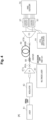
- Fig. 1 illustrates an overview of the present disclosure.
- a bending radius R of a rare-earth doped fiber 90 is appropriately controlled in an optical amplifier 74 that performs amplification by injecting excitation light into the rare-earth doped fiber 90 via a coupler 88.
- optical amplifier 74 that performs amplification by injecting excitation light into the rare-earth doped fiber 90 via a coupler 88.
- optimization aiming at improvement of excitation efficiency has been performed, but there has been no study from the viewpoint of MDG control.
- the bending state affects the MDG, and the MDG is restricted by applying an appropriate bending radius R dependent on a core pitch ⁇ and the core structure of the rare-earth doped fiber 90.
- the rare-earth doped fiber 90 is an erbium doped fiber (EDF) and two cores 91 are disposed in the clad 92 will be described.
- EDF erbium doped fiber
- Fig. 2 illustrates an example of a condition under which each core operates in a single mode.
- the v value is a parameter v in a core of an optical fiber and is calculated by Expression (1).
- [Math. 1] v 2 ⁇ a ⁇ 0 n 1 2 ⁇
- the parameters are as follows.
- Fig. 2 also illustrates an electric field distribution of a guided mode.
- the region In Fig. 2 , only the LP01 mode propagates in the region below the solid line.
- a higher-order mode propagates in the region above the solid line. Therefore, in order to perform a single mode operation, the region needs to be a region below the solid line on which the v value is 2.405. From the above, the v value needs to satisfy the condition of v ⁇ 2.405 in order to get each core behaving in the single mode.
- Fig. 4 illustrates a configuration example of an MDG measurement system regarding the EDF 90.
- a fan-in (FI) device 87A and a fan-out (FO) device 87B for injecting light into each core 91 of the EDF 90 are connected.
- a multi-level phase modulation signal such as quadrature phase shift keying (QPSK) is generated using a laser 81 and a modulator 82, local light from a local oscillation light source 84 is coherently received by a coherent receiver 85, and digital signal processing is performed in a multiple input multiple output (MIMO) equalizer 86.
- QPSK quadrature phase shift keying
- the MIMO equalizer 86 estimates a channel matrix of the part of the EDF 90 and calculates 20log10 ( ⁇ max / ⁇ min ) from the maximum value ⁇ max and the minimum value ⁇ min of a calculated singular value ⁇ m . Accordingly, the MDG in the EDF 90 can be measured. In addition, a localization ratio
- Fig. 5 illustrates MDG calculation results.
- the horizontal axis indicates the localization ratio
- the MDG increases approximately in proportion to the localization ratio under certain conditions. Satisfaction of MDG ⁇ 0.1 dB requires that the localization ratio should satisfy
- Mode coupling in the EDF 90 is not taken into account.
- the EDF 90 having an Er ion density of 100 ppm is used, excitation light of 4 W is output from a multimode laser 83 functioning as an excitation light source, and is injected into the clad of the EDF 90 via the coupler 88, and thus signal light of -25 dBm/core from the laser 81 is excited in the EDF 90.
- step index cores 91 having a core radius of 4.5 um, a relative refractive index difference of 0.35%, a clad diameter of 125 um, and a core pitch ⁇ of 16, 20, 25, and 40 um were used.
- Fig. 6 illustrates a relationship between a localization ratio and a normalized coupling coefficient ⁇ n in a linear state.
- the v value was fixed and set to 2.2, and ⁇ n was changed by changing the core pitch ⁇ in each of the three types of core structures as illustrated in Fig. 7 .
- the localization ratio can be ascertained to be determined by the normalized coupling coefficient ⁇ n even in different core structures.
- Fig. 8 illustrates the relationship between the localization ratio and the normalized coupling coefficient ⁇ n in a plurality of examples regarding the v value.
- ⁇ 0.08 dB in a linear state is a region of ⁇ n ⁇ 8.0 ⁇ 10 -3 , and the range is limited. Further, the range satisfying
- Fig. 9 illustrates a relationship between a bending radius R and a localization ratio
- v value is 2.2
- the normalized coupling coefficient ⁇ n is 1.1 ⁇ 10 -2
- the core pitch ⁇ is 12.4, 16.0, and 19.6 um is illustrated.
- decreases. Therefore, the localization ratio
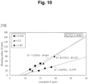
- Fig. 10 illustrates a relationship between the core pitch ⁇ and the bending radius R satisfying
- the bending radius R at each v value can be represented by the following straight lines.
- the MDG can be restricted to 0.1 dB or less.
- Fig. 12 illustrates a relationship between the core pitch ⁇ and the bending radius R satisfying
- 0.08 dB.
- the bending radius R at each v value can be represented by the following straight lines.
- the MDG can be restricted to 0.5 dB or less.
- a fiber structure and a control range of the bending radius R for restricting the MDG to a sufficiently small value have been clarified. Therefore, by adopting the optical amplifier 74 of the present disclosure, it is practical to provide an optical amplifier of a coupled MCF having low MDG characteristics.
Landscapes
- Physics & Mathematics (AREA)
- Electromagnetism (AREA)
- Engineering & Computer Science (AREA)
- Plasma & Fusion (AREA)
- Optics & Photonics (AREA)
- Computer Networks & Wireless Communication (AREA)
- Signal Processing (AREA)
- Microelectronics & Electronic Packaging (AREA)
- Lasers (AREA)
Abstract
Description
- The present disclosure relates to a rare-earth doped fiber, an optical amplifier using the rare-earth doped fiber, and a method of controlling the optical amplifier.
- A coupled multi-core fiber (MCF) has excellent mode dispersion characteristics produced by random coupling, and thus has attracted attention as an optical fiber for space division multiplexing (SDM) suitable for long-distance large-capacity transmission. In order to realize long-distance transmission using a coupled MCF, an optical amplification relay technology is required, and studies have been made to apply the coupled MCF to an optical amplifier [refer to
Non Patent Literature 1, for example]. - In a transmission system using a coupled MCF, a mode dependent gain (MDG) in an optical amplifier is a problem. According to
Non Patent Literature 1, the MDG in the optical amplifier is an important constraint factor on a transmission distance of the transmission system using the coupled MCF. - Non Patent Literature 1: T. Sakamoto et al., "Characteristics of Randomly Coupled 12-core Erbium-Doped Fiber Amplifier," J. Light. Technol., vol. 39, no. 4, pp.1186-1193, 2021.
- Therefore, an object of the present disclosure is to reduce mode-dependent gain characteristics in an optical amplifier using a coupled multi-core fiber.
- In the present disclosure, a rare-earth doped fiber, in which each core operates in a single mode and a localization ratio of modes is restricted, is applied to an optical amplifier.
- Specifically, a rare-earth doped fiber of the present disclosure is a rare-earth doped fiber including a plurality of cores, in which a v value of the plurality of cores is less than 2.405, and the plurality of cores has a core pitch of a normalized coupling coefficient of 1.0 × 10⁻³ or more.
- An optical amplifier of the present disclosure includes the rare-earth doped fiber according to the present disclosure, and amplifies propagating light in the rare-earth doped fiber, with mode-dependent gain characteristics dependent on a predetermined bending radius, on injection of excitation light into a clad part of the rare-earth doped fiber in a state of being bent at the bending radius.
- A method of the present disclosure is a method of controlling the optical amplifier of the present disclosure and includes reducing the mode-dependent gain characteristics by bending at the predetermined bending radius.
- According to the present disclosure, mode-dependent gain characteristics in an optical amplifier using a coupled multi-core fiber can be reduced.
-
-
Fig. 1 illustrates a configuration example of an optical amplifier of the present disclosure. -
Fig. 2 illustrates an example of conditions under which each core operates in a single mode. -
Fig. 3 illustrates an example of a refractive index distribution of a rare-earth doped fiber of the present disclosure. -
Fig. 4 illustrates a configuration example of an MDG measurement system regarding an EDF. -
Fig. 5 illustrates MDG calculation results. -
Fig. 6 illustrates a relationship between a localization ratio and a normalized coupling coefficient κn in a linear state. -
Fig. 7 illustrates examples of core structures. -
Fig. 8 illustrates a relationship between a localization ratio and a normalized coupling coefficient κn in a plurality of examples regarding a v value. -
Fig. 9 illustrates a relationship between a bending radius R and a localization ratio |Γe/Γο| at a certain v value and κn. -
Fig. 10 illustrates an example of a relationship between a core pitch Λ and a bending radius R satisfying |Γe/Γο| = 0.02 dB. -
Fig. 11 illustrates an example of a relationship between a v value and coefficients a and b. -
Fig. 12 illustrates a relationship between a core pitch Λ and a bending radius R satisfying |Γe/Γο| = 0.08 dB. -
Fig. 13 illustrates an example of a relationship between a v value and coefficients a and b. -
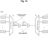
Fig. 14 illustrates a configuration example of a transmission system to which an optical amplifier of the present disclosure is applied. - Hereinafter, embodiments of the present disclosure will be described in detail with reference to the drawings. Note that the present disclosure is not limited to the following embodiments. These examples are merely examples, and the present disclosure can be implemented in a form with various modifications and improvements based on the knowledge of those skilled in the art. Note that components having the same reference numerals in the present specification and the drawings indicate the same components.
-
Fig. 1 illustrates an overview of the present disclosure. In the present disclosure, a bending radius R of a rare-earth dopedfiber 90 is appropriately controlled in anoptical amplifier 74 that performs amplification by injecting excitation light into the rare-earth dopedfiber 90 via acoupler 88. In studies on conventional coupled optical amplifiers (for example, Non Patent Literature 1), optimization aiming at improvement of excitation efficiency has been performed, but there has been no study from the viewpoint of MDG control. In the present disclosure, it is clarified that, in addition to the structure ofcores 91 disposed in aclad 92, the bending state affects the MDG, and the MDG is restricted by applying an appropriate bending radius R dependent on a core pitch Λ and the core structure of the rare-earth dopedfiber 90. Hereinafter, in the present disclosure, as an embodiment, an example in which the rare-earth dopedfiber 90 is an erbium doped fiber (EDF) and twocores 91 are disposed in theclad 92 will be described. -
Fig. 2 illustrates an example of a condition under which each core operates in a single mode.Fig. 2 illustrates a relationship between a core radius a and a relative refractive index difference Δ, for the sake of a v value of a step index type fiber having a refractive index distribution, as illustrated inFig. 3 , satisfying v = 2.405. - Here, the v value is a parameter v in a core of an optical fiber and is calculated by Expression (1).
[Math. 1]
The parameters are as follows. - a: core radius of
EDF 90 - λ0: wavelength used (wavelength in vacuum)
- n1: refractive index of
cores 91 of EDF 90 - Δ: relative refractive index difference of EDF 90
-
Fig. 2 also illustrates an electric field distribution of a guided mode. InFig. 2 , only the LP01 mode propagates in the region below the solid line. On the other hand, a higher-order mode propagates in the region above the solid line. Therefore, in order to perform a single mode operation, the region needs to be a region below the solid line on which the v value is 2.405. From the above, the v value needs to satisfy the condition of v < 2.405 in order to get each core behaving in the single mode. -
Fig. 4 illustrates a configuration example of an MDG measurement system regarding theEDF 90. To the input/output ends of the EDF 90, a fan-in (FI)device 87A and a fan-out (FO)device 87B for injecting light into eachcore 91 of the EDF 90 are connected. In the evaluation of inter-mode characteristic differences, a multi-level phase modulation signal such as quadrature phase shift keying (QPSK) is generated using alaser 81 and amodulator 82, local light from a localoscillation light source 84 is coherently received by acoherent receiver 85, and digital signal processing is performed in a multiple input multiple output (MIMO)equalizer 86. TheMIMO equalizer 86 estimates a channel matrix of the part of theEDF 90 and calculates 20log10 (λmax/λmin) from the maximum value λmax and the minimum value λmin of a calculated singular value λm. Accordingly, the MDG in the EDF 90 can be measured. In addition, a localization ratio |Γe/Γο| between an even mode and an odd mode in the EDF 90 can also be measured. -
Fig. 5 illustrates MDG calculation results. The horizontal axis indicates the localization ratio |Γe/Γο| between an even mode and an odd mode, and the vertical axis indicates the MDG. Both values are in dB. As illustrated in the figure, it can be ascertained that the MDG increases approximately in proportion to the localization ratio under certain conditions. Satisfaction of MDG < 0.1 dB requires that the localization ratio should satisfy |Γe/Γο| < 0.02 dB. Further, satisfaction of MDG < 0.5 dB requires |Γe/Γο| < 0.08 dB. - Mode coupling in the
EDF 90 is not taken into account. In simulations, theEDF 90 having an Er ion density of 100 ppm is used, excitation light of 4 W is output from amultimode laser 83 functioning as an excitation light source, and is injected into the clad of theEDF 90 via thecoupler 88, and thus signal light of -25 dBm/core from thelaser 81 is excited in theEDF 90. In addition,step index cores 91 having a core radius of 4.5 um, a relative refractive index difference of 0.35%, a clad diameter of 125 um, and a core pitch Λ of 16, 20, 25, and 40 um were used. -
Fig. 6 illustrates a relationship between a localization ratio and a normalized coupling coefficient κn in a linear state. The v value was fixed and set to 2.2, and κn was changed by changing the core pitch Λ in each of the three types of core structures as illustrated inFig. 7 . When the v value is constant, the localization ratio can be ascertained to be determined by the normalized coupling coefficient κn even in different core structures. -
Fig. 8 illustrates the relationship between the localization ratio and the normalized coupling coefficient κn in a plurality of examples regarding the v value. The range satisfying |Γe/Γο| < 0.08 dB in a linear state is a region of κn < 8.0 × 10⁻³, and the range is limited. Further, the range satisfying |Γe/Γο| < 0.02 dB in a linear state is a region of approximately κn < 1.0 × 10⁻³, and the range is further limited. -
Fig. 9 illustrates a relationship between a bending radius R and a localization ratio |Γe/Γο| at a certain v value and κn. In this example, a condition in which the v value is 2.2, the normalized coupling coefficient κn is 1.1 × 10⁻², and the core pitch Λ is 12.4, 16.0, and 19.6 um is illustrated. - As illustrated in
Fig. 9 , as the bending radius R decreases, the localization ratio |Γe/Γο| decreases. Therefore, the localization ratio |Γe/Γο| and the MDG can be ascertained to be reducible by means of suitable control of the bending radius R in the core structure in which |Γe/Γο| is high in a linear state, that is, in the region of κn ≥ 1.0 × 10⁻³. -
Fig. 10 illustrates a relationship between the core pitch Λ and the bending radius R satisfying |Γe/Γο| = 0.02 dB. Examples, in which the v value is set to 2.405, 2.2, and 1.85 separately, were plotted. All normalized coupling coefficients were calculated as κn = 1.1 × 10⁻². The bending radius R at each v value can be represented by the following straight lines. - v value = 2.405: R = 7.3529Λ - 59.461
- v value = 2.2: R = 8.3333Λ - 83.333
- v value = 1.85: R = 3.6479Λ - 31.979
- In
Fig. 10 , |Γe/Γo| < 0.02 dB can be obtained in a region below any of the straight lines, and an MDG of 0.1 dB or less can be achieved. The straight lines inFig. 10 represent Expression (2) using the v value and Λ. Here, coefficients a and b in Expression (2) can be calculated as follows by fitting as illustrated inFig. 11 .


- Therefore, by controlling the bending radius R within a range satisfying Expression (2), the MDG can be restricted to 0.1 dB or less.
- Similarly,
Fig. 12 illustrates a relationship between the core pitch Λ and the bending radius R satisfying |Γe/Γο| = 0.08 dB. The bending radius R at each v value can be represented by the following straight lines. - v value = 2.405: R = 32.353Λ - 226.96
- v value = 2.2: R = 13.889Λ - 45.556
- v value = 1.85: R = 14.592Λ - 107.91
- In
Fig. 12 , |Γe/Γο| < 0.08 dB can be obtained in a region below any of the straight lines, and an MDG of 0.5 dB or less can be achieved. The straight lines inFig. 12 represent Expression (3) using the v value and Λ. Here, the coefficients a and b in Expression (3) can be calculated as follows by fitting as illustrated inFig. 13 .


- Therefore, by controlling the bending radius R within a range satisfying Expression (3), the MDG can be restricted to 0.5 dB or less.
- According to the present disclosure, a fiber structure and a control range of the bending radius R for restricting the MDG to a sufficiently small value have been clarified. Therefore, by adopting the
optical amplifier 74 of the present disclosure, it is practical to provide an optical amplifier of a coupled MCF having low MDG characteristics. - Although an example in which the normalized coupling coefficient κn is 1.1 × 10⁻² has been illustrated in the present embodiment, the present disclosure is not limited thereto. For example, the present disclosure is applicable to any value of normalized coupling coefficient κn equal to or more than 1.1 × 10⁻³ in order to adjust the localization ratio in a bent state. However, when the normalized coupling coefficient κn is 0.1 or more, the
cores 91 are in contact with each other as can be ascertained fromFig. 8 , and thus the normalized coupling coefficient κn is preferably less than 0.1. - Further, although an example in which the rare-earth doped
fiber 90 is a two-core EDF has been illustrated in the present embodiment, the present disclosure is not limited thereto. For example, the present disclosure is not limited to an EDF, and any rare-earth doped fiber may be used. In addition, the above-described design method may be applied to a rare-earth doped fiber having three or more cores. -
Fig. 14 illustrates a configuration example of a transmission system to which the optical amplifier of the present disclosure is applied. The transmission system of the present disclosure is a space division multiplexing transmission system that transmits signal light from a plurality ofoptical transmitters 71 to a plurality ofreceivers 72 using space division multiplexing transmission such as mode division multiplexing. In the space division multiplexing transmission system of the present disclosure, aMUX 75 that performs fan-in and a DEMUX 76 that performs fan-out are connected to each other via a coupledMCF 73. As illustrated inFig. 1 , theoptical amplifier 74 of the present disclosure amplifies each signal light transmitted through the coupledMCF 73 in a state of being bent at a bending radius R. - As described above, the
optical amplifier 74 of the present disclosure can amplify the space division multiplexed light transmitted through the coupledMCF 73, with low mode-dependent gain characteristics, in the space division multiplexing transmission system. Therefore, the present disclosure can realize long-distance transmission by the coupledMCF 73. - The present disclosure can be applied to the information communication industry.
-
- 71
- Transmitter
- 72
- Receiver
- 73
- Coupled MCF
- 74
- Optical amplifier
- 75
- MUX
- 76
- DEMUX
- 81
- Laser
- 82
- Modulator
- 83
- Multimode laser
- 84
- Local oscillation light source
- 85
- Coherent receiver
- 86
- MIMO equalizer
- 87A
- Fan-in device
- 87B
- Fan-out device
- 88
- Coupler
- 89A, 89B
- Isolator
- 90
- Rare-earth doped fiber
- 91
- Core
- 92
- Clad
Claims (5)
- A rare-earth doped fiber including a plurality of cores,
whereina v value of the plurality of cores is less than 2.405, andthe plurality of cores has a core pitch of a normalized coupling coefficient of 1.0 × 10⁻³ or more. - An optical amplifier comprising the rare-earth doped fiber according to claim 1,
wherein the optical amplifier amplifies propagating light in the rare-earth doped fiber, with mode-dependent gain characteristics dependent on a predetermined bending radius, on injection of excitation light into a clad part of the rare-earth doped fiber in a state of being bent at the bending radius. - A method of controlling the optical amplifier according to claim 2, the method comprising reducing the mode-dependent gain characteristics by bending at the predetermined bending radius.
- The method according to claim 3, wherein the rare-earth doped fiber is a two-core erbium doped fiber having a core pitch A,
the method comprising controlling a bending radius R based on the following expression to keep the mode-dependent gain characteristics 0.1 dB or less:


- The method according to claim 3, wherein the rare-earth doped fiber is a two-core erbium doped fiber having a core pitch A,
the method comprising controlling a bending radius R based on the following expression to keep the mode-dependent gain characteristics 0.5 dB or less:


Applications Claiming Priority (1)
| Application Number | Priority Date | Filing Date | Title |
|---|---|---|---|
| PCT/JP2022/004159 WO2023148863A1 (en) | 2022-02-03 | 2022-02-03 | Rare-earth-doped fiber, optical amplifier, and method for controlling optical amplifier |
Publications (3)
| Publication Number | Publication Date |
|---|---|
| EP4475357A1 true EP4475357A1 (en) | 2024-12-11 |
| EP4475357A9 EP4475357A9 (en) | 2025-03-05 |
| EP4475357A4 EP4475357A4 (en) | 2025-12-17 |
Family
ID=87553367
Family Applications (1)
| Application Number | Title | Priority Date | Filing Date |
|---|---|---|---|
| EP22924774.7A Pending EP4475357A4 (en) | 2022-02-03 | 2022-02-03 | RARE-EARTH-DOP FIBER, OPTICAL AMPLIFIER, AND METHOD FOR CONTROLLING THE OPTICAL AMPLIFIER |
Country Status (4)
| Country | Link |
|---|---|
| US (1) | US20250118941A1 (en) |
| EP (1) | EP4475357A4 (en) |
| JP (1) | JPWO2023148863A1 (en) |
| WO (1) | WO2023148863A1 (en) |
Family Cites Families (8)
| Publication number | Priority date | Publication date | Assignee | Title |
|---|---|---|---|---|
| JP2834867B2 (en) * | 1990-07-31 | 1998-12-14 | 富士通株式会社 | Erbium-doped fiber amplifier |
| US7280730B2 (en) * | 2004-01-16 | 2007-10-09 | Imra America, Inc. | Large core holey fibers |
| JP2015510253A (en) * | 2011-12-13 | 2015-04-02 | オーエフエス ファイテル,エルエルシー | Multi-core erbium-doped fiber amplifier |
| JP6445938B2 (en) * | 2015-07-07 | 2018-12-26 | 日本電信電話株式会社 | Multi-core optical fiber and optical amplifier |
| JP2017072818A (en) * | 2015-10-08 | 2017-04-13 | 住友電気工業株式会社 | Multi-core optical fiber, multi-core optical fiber cable and optical fiber transmission system |
| JP6668833B2 (en) * | 2016-03-09 | 2020-03-18 | 住友電気工業株式会社 | Coupled multi-core optical fiber |
| JP2019075450A (en) * | 2017-10-16 | 2019-05-16 | 住友電気工業株式会社 | Optical amplifier and multi-core optical fiber |
| JPWO2020067383A1 (en) * | 2018-09-28 | 2021-08-30 | 住友電気工業株式会社 | Fiber optic amplifier |
-
2022
- 2022-02-03 WO PCT/JP2022/004159 patent/WO2023148863A1/en not_active Ceased
- 2022-02-03 EP EP22924774.7A patent/EP4475357A4/en active Pending
- 2022-02-03 JP JP2023578256A patent/JPWO2023148863A1/ja active Pending
- 2022-02-03 US US18/832,029 patent/US20250118941A1/en active Pending
Also Published As
| Publication number | Publication date |
|---|---|
| JPWO2023148863A1 (en) | 2023-08-10 |
| EP4475357A4 (en) | 2025-12-17 |
| US20250118941A1 (en) | 2025-04-10 |
| EP4475357A9 (en) | 2025-03-05 |
| WO2023148863A1 (en) | 2023-08-10 |
Similar Documents
| Publication | Publication Date | Title |
|---|---|---|
| US6359725B1 (en) | Multi-stage optical amplifier and broadband communication system | |
| EP1283566B1 (en) | Optical amplifier for amplifying multi-wavelength light | |
| US5600481A (en) | Optical fiber amplifier and optical transmission system using the same | |
| US6335820B1 (en) | Multi-stage optical amplifier and broadband communication system | |
| EP2791719B1 (en) | Multi-core erbium-doped fiber amplifier | |
| US6377391B1 (en) | Gain flattening with nonlinear Sagnac amplifiers | |
| US6191854B1 (en) | Optical telecommunications system | |
| EP2822112B1 (en) | High-power double-cladding-pumped (DC) erbium-doped fiber amplifier (EDFA) | |
| US6538807B2 (en) | Amplification optical fiber, fiber optic amplifier, optical transmitter, and optical communication system | |
| EP1775863A2 (en) | Raman amplifier | |
| JP2001251006A (en) | Distributed optical amplifying apparatus and method and optical communication system | |
| WO2003055017A1 (en) | Raman amplification using a microstructured fiber | |
| EP1164412B1 (en) | Optical transimission line enabling Raman amplification and optical transmission system | |
| EP4475357A9 (en) | Rare-earth-doped fiber, optical amplifier, and method for controlling optical amplifier | |
| EP1343229A2 (en) | Dispersion-compensated erbium-doped fiber amplifier | |
| US20040196882A1 (en) | Optical amplifier | |
| KR20010041602A (en) | Ultra-Broadband Low-Noise Gain-Flattened Rare-Earth-Doped Fibre Amplifier | |
| EP1189315B1 (en) | Optical amplifier and optical transmission system using same | |
| EP1220381A2 (en) | Amplification optical fiber and fiber optic amplifier including the same | |
| US6804046B2 (en) | Optical amplification fiber, fiber optic amplifier, and optical communication system | |
| JP2003258348A (en) | Optical amplifier and optical communication system | |
| Kim et al. | Distributed fiber Raman amplifiers with localized loss | |
| EP0887956B1 (en) | Optical telecommunications system with chromatic dispersion compensator | |
| JP2002151772A (en) | Optical amplification fiber, optical fiber amplifier and optical communication system | |
| Zervas et al. | Advanced erbium-doped fiber amplifiers: channel equalizers |
Legal Events
| Date | Code | Title | Description |
|---|---|---|---|
| STAA | Information on the status of an ep patent application or granted ep patent |
Free format text: STATUS: THE INTERNATIONAL PUBLICATION HAS BEEN MADE |
|
| PUAI | Public reference made under article 153(3) epc to a published international application that has entered the european phase |
Free format text: ORIGINAL CODE: 0009012 |
|
| STAA | Information on the status of an ep patent application or granted ep patent |
Free format text: STATUS: REQUEST FOR EXAMINATION WAS MADE |
|
| 17P | Request for examination filed |
Effective date: 20240715 |
|
| AK | Designated contracting states |
Kind code of ref document: A1 Designated state(s): AL AT BE BG CH CY CZ DE DK EE ES FI FR GB GR HR HU IE IS IT LI LT LU LV MC MK MT NL NO PL PT RO RS SE SI SK SM TR |
|
| DAV | Request for validation of the european patent (deleted) | ||
| DAX | Request for extension of the european patent (deleted) | ||
| RAP3 | Party data changed (applicant data changed or rights of an application transferred) |
Owner name: NTT, INC. |
|
| A4 | Supplementary search report drawn up and despatched |
Effective date: 20251118 |
|
| RIC1 | Information provided on ipc code assigned before grant |
Ipc: H01S 3/067 20060101AFI20251112BHEP Ipc: H04B 10/291 20130101ALI20251112BHEP Ipc: H01S 3/00 20060101ALN20251112BHEP Ipc: H01S 3/08045 20230101ALN20251112BHEP Ipc: H01S 3/094 20060101ALN20251112BHEP Ipc: H01S 3/16 20060101ALN20251112BHEP |