EP4475354A1 - Socket - Google Patents
Socket Download PDFInfo
- Publication number
- EP4475354A1 EP4475354A1 EP22924202.9A EP22924202A EP4475354A1 EP 4475354 A1 EP4475354 A1 EP 4475354A1 EP 22924202 A EP22924202 A EP 22924202A EP 4475354 A1 EP4475354 A1 EP 4475354A1
- Authority
- EP
- European Patent Office
- Prior art keywords
- lever
- restriction member
- rotation axis
- restriction
- operating portion
- Prior art date
- Legal status (The legal status is an assumption and is not a legal conclusion. Google has not performed a legal analysis and makes no representation as to the accuracy of the status listed.)
- Pending
Links
Images



Classifications
-
- H—ELECTRICITY
- H01—ELECTRIC ELEMENTS
- H01R—ELECTRICALLY-CONDUCTIVE CONNECTIONS; STRUCTURAL ASSOCIATIONS OF A PLURALITY OF MUTUALLY-INSULATED ELECTRICAL CONNECTING ELEMENTS; COUPLING DEVICES; CURRENT COLLECTORS
- H01R9/00—Structural associations of a plurality of mutually-insulated electrical connecting elements, e.g. terminal strips or terminal blocks; Terminals or binding posts mounted upon a base or in a case; Bases therefor
- H01R9/22—Bases, e.g. strip, block, panel
- H01R9/24—Terminal blocks
- H01R9/26—Clip-on terminal blocks for side-by-side rail- or strip-mounting
- H01R9/2616—End clamping members
-
- H—ELECTRICITY
- H01—ELECTRIC ELEMENTS
- H01H—ELECTRIC SWITCHES; RELAYS; SELECTORS; EMERGENCY PROTECTIVE DEVICES
- H01H50/00—Details of electromagnetic relays
- H01H50/02—Bases; Casings; Covers
- H01H50/04—Mounting complete relay or separate parts of relay on a base or inside a case
- H01H50/047—Details concerning mounting a relays
- H01H50/048—Plug-in mounting or sockets
-
- H—ELECTRICITY
- H01—ELECTRIC ELEMENTS
- H01R—ELECTRICALLY-CONDUCTIVE CONNECTIONS; STRUCTURAL ASSOCIATIONS OF A PLURALITY OF MUTUALLY-INSULATED ELECTRICAL CONNECTING ELEMENTS; COUPLING DEVICES; CURRENT COLLECTORS
- H01R13/00—Details of coupling devices of the kinds covered by groups H01R12/70 or H01R24/00 - H01R33/00
- H01R13/62—Means for facilitating engagement or disengagement of coupling parts or for holding them in engagement
- H01R13/629—Additional means for facilitating engagement or disengagement of coupling parts, e.g. aligning or guiding means, levers, gas pressure electrical locking indicators, manufacturing tolerances
- H01R13/62933—Comprising exclusively pivoting lever
- H01R13/62955—Pivoting lever comprising supplementary/additional locking means
-
- H—ELECTRICITY
- H01—ELECTRIC ELEMENTS
- H01R—ELECTRICALLY-CONDUCTIVE CONNECTIONS; STRUCTURAL ASSOCIATIONS OF A PLURALITY OF MUTUALLY-INSULATED ELECTRICAL CONNECTING ELEMENTS; COUPLING DEVICES; CURRENT COLLECTORS
- H01R13/00—Details of coupling devices of the kinds covered by groups H01R12/70 or H01R24/00 - H01R33/00
- H01R13/62—Means for facilitating engagement or disengagement of coupling parts or for holding them in engagement
- H01R13/629—Additional means for facilitating engagement or disengagement of coupling parts, e.g. aligning or guiding means, levers, gas pressure electrical locking indicators, manufacturing tolerances
- H01R13/633—Additional means for facilitating engagement or disengagement of coupling parts, e.g. aligning or guiding means, levers, gas pressure electrical locking indicators, manufacturing tolerances for disengagement only
- H01R13/635—Additional means for facilitating engagement or disengagement of coupling parts, e.g. aligning or guiding means, levers, gas pressure electrical locking indicators, manufacturing tolerances for disengagement only by mechanical pressure, e.g. spring force
-
- H—ELECTRICITY
- H01—ELECTRIC ELEMENTS
- H01R—ELECTRICALLY-CONDUCTIVE CONNECTIONS; STRUCTURAL ASSOCIATIONS OF A PLURALITY OF MUTUALLY-INSULATED ELECTRICAL CONNECTING ELEMENTS; COUPLING DEVICES; CURRENT COLLECTORS
- H01R13/00—Details of coupling devices of the kinds covered by groups H01R12/70 or H01R24/00 - H01R33/00
- H01R13/62—Means for facilitating engagement or disengagement of coupling parts or for holding them in engagement
- H01R13/639—Additional means for holding or locking coupling parts together, after engagement, e.g. separate keylock, retainer strap
-
- H—ELECTRICITY
- H01—ELECTRIC ELEMENTS
- H01R—ELECTRICALLY-CONDUCTIVE CONNECTIONS; STRUCTURAL ASSOCIATIONS OF A PLURALITY OF MUTUALLY-INSULATED ELECTRICAL CONNECTING ELEMENTS; COUPLING DEVICES; CURRENT COLLECTORS
- H01R9/00—Structural associations of a plurality of mutually-insulated electrical connecting elements, e.g. terminal strips or terminal blocks; Terminals or binding posts mounted upon a base or in a case; Bases therefor
- H01R9/22—Bases, e.g. strip, block, panel
- H01R9/24—Terminal blocks
- H01R9/26—Clip-on terminal blocks for side-by-side rail- or strip-mounting
- H01R9/2625—Clip-on terminal blocks for side-by-side rail- or strip-mounting with built-in electrical component
-
- H—ELECTRICITY
- H01—ELECTRIC ELEMENTS
- H01R—ELECTRICALLY-CONDUCTIVE CONNECTIONS; STRUCTURAL ASSOCIATIONS OF A PLURALITY OF MUTUALLY-INSULATED ELECTRICAL CONNECTING ELEMENTS; COUPLING DEVICES; CURRENT COLLECTORS
- H01R9/00—Structural associations of a plurality of mutually-insulated electrical connecting elements, e.g. terminal strips or terminal blocks; Terminals or binding posts mounted upon a base or in a case; Bases therefor
- H01R9/22—Bases, e.g. strip, block, panel
- H01R9/24—Terminal blocks
- H01R9/26—Clip-on terminal blocks for side-by-side rail- or strip-mounting
- H01R9/2625—Clip-on terminal blocks for side-by-side rail- or strip-mounting with built-in electrical component
- H01R9/2633—Clip-on terminal blocks for side-by-side rail- or strip-mounting with built-in electrical component with built-in switch
Definitions
- the present disclosure relates to a socket.
- Patent Document 1 discloses a relay socket including a release lever capable of preventing a relay mounted on a relay mounting portion from rotating and dropping off.
- the release lever includes an abutment portion, which faces a back surface of the relay mounted on the relay mounting portion, and an operating portion, which is continuous with the abutment portion and extends to a front surface side.
- the release lever is configured to be swingable between a holding position and a retraction position.
- Patent Document 1 JP 2005-108767 A
- An object of the present disclosure is to provide a socket capable of preventing an electronic device connected thereof from dropping off due to rotation of a lever.
- a socket according to one aspect of the present disclosure includes:
- a socket is achieved that is capable of preventing an electronic device connected thereof from dropping off due to rotation of a lever.
- a socket 1 of the present disclosure includes a housing 10, a lever 20 rotatably attached to the housing 10, and a restriction member 30.
- the housing 10 includes a first wall portion 11 which includes a connection surface 111 to which an electronic device 50 includes an electromagnetic relay is connected, and a second wall portion 12.
- the housing 10 includes a housing main body 101 which has a thin plate shape and includes an opening 103 at one end in a thickness direction (for example, Y direction), and a lid portion 102 which closes the opening 103 of the housing main body 101.
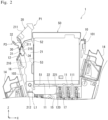
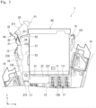
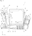
- Figs. 2 to 4 show the socket 1 with the lid portion 102 removed.
- the first wall portion 11 is located substantially at a center in a width direction of the housing main body 101 (for example, X direction, hereinafter referred to as a first direction).
- the first wall portion 11 extends in the first direction X and has a thickness along a height direction (for example, the Z direction) of the housing 10.
- the connection surface 111 constitutes a part of an outer surface of the housing main body 101 and extends in the XY directions.
- the connection surface 111 includes an opening (not illustrated) configured to accommodate a contact portion 22 of the lever 20 described below and a plurality of openings (not illustrated) each configured to accommodate a terminal 120 extending from the electronic device 50.
- the second wall portion 12 is positioned with a gap 16 from the first wall portion 11 in the first direction X along the connection surface 111.
- the lever 20 is located in the gap 16.
- the second wall portion 12 extends in a second direction (for example, Z direction) intersecting the connection surface 111 and in a direction from the connection surface 111 toward an outside of the housing 10.
- the housing 10 is configured to be attachable to an external device (not illustrated) such as a control panel via an attachment portion 13 located on a side opposite to the connection surface 111 in the second direction Z.
- an external device such as a control panel
- a plurality of wiring connection portions 14 is provided on both sides of the first wall portion 11 in the first direction X of the housing 10.
- External wiring (not illustrated) is connected to each wiring connection portion 14.
- the electronic device 50 has a substantially rectangular parallelepiped shape and includes a bottom portion 51 and a side portion 52.
- the bottom portion 51 faces the connection surface 111 in a state in which the electronic device 50 is connected to the connection surface 111.
- the side portion 52 extends in the second direction Z and faces an operating portion 21 of the lever 20 in the first direction X in a state in which the electronic device 50 is connected to the connection surface 111.
- a projection 53 is provided in the middle in the second direction Z of the side portion 52 of the electronic device 50.
- the bottom portion 51 of the electronic device 50 includes a terminal 54 extending from the bottom portion 51 in the second direction Z and accommodated in the housing 10.
- the terminal 54 is connected to a terminal connection portion 17 provided inside the housing 10.
- the terminal connection portion 17 includes a pair of leaf springs configured to hold the terminal 54 from the first direction X.
- the lever 20 is attached to the housing 10 so as to be rotatable about a rotation axis L1 extending along the connection surface 111.
- the lever 20 has a substantially L shape as a whole, and includes an operating portion 21 and a contact portion 22.
- the rotation axis L1 is located at an end portion 212 of the operating portion 21 located inside the housing 10 (in other words, the end portion 212 at one of the two ends of the operating portion 21 in a direction in which the operating portion 21 extends that is closer to the connection surface 111).
- the operating portion 21 has a rod shape extending from the rotation axis L1 in a radial direction with respect to the rotation axis L1 (hereinafter referred to as a radial direction). As illustrated in Fig. 1 , an end portion 211 at one of the two ends of the operating portion 21 in the direction in which the operating portion 21 extends that is farther from the rotation axis L1 is located outside the housing 10.
- the operating portion 21 includes a first recess 213 (see Fig. 6 ) and a second recess 214 (see Fig. 6 ), which open in a width direction intersecting a circumferential direction and the radial direction (e.g., Y direction), a third recess 215 (see Fig. 6 ), which opens facing the restriction member 30 in the circumferential direction, and a fourth recess 216 (see Fig. 5 ), which opens facing the electronic device 50 in the circumferential direction.
- the operating portion 21 includes a pair of first recesses 213 and a pair of second recesses 214. Each recess of the pair of first recesses 213 opens in mutually opposite direction in the width direction Y, and each recess of the pair of second recesses 214 opens in mutually opposite direction in the width direction Y.
- Each first recess 213 and each second recess 214 are configured to accommodate and hold first protruding portions 33 of the restriction member 30 described below (see Fig. 7 ).
- Each first recess 213 is located closer to the rotation axis L1 than each second recess 214 in the radial direction.
- Each first recess 213 is provided at a position corresponding to a restriction position P3 of the restriction member 30 described below.
- Each second recess 214 is provided at a position corresponding to a release position P4 of the restriction member 30 described below.
- the operating portion 21 includes a support wall portion 23 that protrudes from a surface facing the restriction member 30 in the circumferential direction and an approaching direction toward the restriction member 30 and extends in the radial direction.
- the support wall portion 23 includes a groove portion 231 extending in the radial direction on both sides in the width direction Y.
- One first recess 213 and one second recess 214 are provided in a bottom surface 232 of each groove portion 231.
- the third recess 215 extends along the radial direction and is configured to accommodate a second protruding portion 34 of the restriction member 30 described below (see Fig. 2 ).
- an inclined surface 217 is provided at one of the two ends in the radial direction of the third recess 215 that is closer to the rotation axis L1 (in other words, the end farther from the support wall portion 23).
- the inclined surface 217 is inclined from an opening of the third recess 215 toward a bottom surface of the third recess 215 in the circumferential direction with increasing distance from the rotation axis L1 in the radial direction.
- the fourth recess 216 is configured to accommodate the projection 53 of the electronic device 50 when the operating portion 21 is located at a first position P1 (see Fig. 2 ).
- a movement of the electronic device 50 in the second direction Z and in a direction away from the connection surface 111 is restricted.
- a contact portion 22 extends from the end portion 212 at one of the two ends of the operating portion 21 in the direction in which the operating portion 21 extends that is closer to the rotation axis L1, in the radial direction and in a direction intersecting the direction in which the operating portion 21 extends.
- the contact portion 22 is configured to rotate about the rotation axis L1 together with the operating portion 21.
- the lever 20 is configured to rotate about the rotation axis L1 between the first position P1 and a second position P2.
- the first position P1 is a position at which the operating portion 21 is adjacent to the electronic device 50 connected to the connection surface 111 in the circumferential direction with respect to the rotation axis L1 (hereinafter referred to as the circumferential direction).
- the circumferential direction movement of the lever 20 in the circumferential direction and in a direction toward the electronic device 50 is restricted by a projection 15 provided on the housing 10.
- the projection 15 is located farther from the connection surface 111 than the contact portion 22 in the circumferential direction.
- the contact portion 22 is configured to be capable of coming into contact with the projection 15 at the first position P1.
- the second position P2 is a position at which the operating portion 21 is farther from the side portion 52 of the electronic device 50 connected to the connection surface 111 than the first position P1 in the circumferential direction, and is a position adjacent to the second wall portion 12 of the housing 10.
- the operating portion 21 is configured such that the bottom surface of the third recess 215 comes into contact with the second wall portion 12 of the housing 10 at the second position P2. That is, a rotation range of the lever 20 is defined by the housing 10.
- the contact portion 22 when the lever 20 is located at the first position P1, the contact portion 22 is located inside the housing 10 in a state in which a distal end portion 221, which is an end portion farther from the operating portion 21 in the first direction X, faces the connection surface 111 in the circumferential direction. As illustrated in Fig. 4 , when the lever 20 is located at the second position P2, the contact portion 22 is located outside the housing 10 with the distal end portion 221 facing the connection surface 111 in the circumferential direction.
- the contact portion 22 presses the bottom portion 51 of the electronic device 50 to move the electronic device 50 in the second direction Z and in the direction away from the connection surface 111. As a result, the electronic device 50 is disconnected from the socket 1.
- the restriction member 30 is attached to, as an example, the operating portion 21 in a state in which the restriction member 30 is movable along the radial direction between a restriction position P3 and a release position P4.
- the restriction position P3 is a position that the restriction member 30 is located between the operating portion 21 and the second wall portion 12 in the circumferential direction and restricts the rotation of the lever 20.
- the release position P4 is a position farther from the rotation axis L1 than the restriction position P3 in the radial direction, and is a position at which the restriction of the rotation of the lever 20 by the restriction member 30 is released.
- the restriction member 30 includes a main body portion 31, and a pinch portion 32, a first protruding portion 33, and a second protruding portion 34.
- the pinch portion 32, the first protruding portion 33, and the second protruding portion 34 are provided on the main body portion 31 respectively.
- the restriction member 30 includes a pair of first protruding portions 33 and a pair of second protruding portions 34.
- the main body portion 31 includes a pair of wall portions 311 each having a shape of a substantially rectangular plate with the radial direction as a longitudinal direction thereof and each extending from an end closer to the rotation axis L1 to approximately a center of the main body portion 31.
- the wall portions 311 are positioned with a gap 312 therebetween in the width direction Y.
- the pinch portion 32 is located at one of the two ends of the main body portion 31 in the radial direction that is farther from the rotation axis L1.
- the pinch portion 32 has a shape of a substantially rectangular thin plate (see Fig. 7 ). As viewed along the width direction Y, the pinch portion 32 extends in a direction away from the main body portion 31 in the circumferential direction and in a direction away from the rotation axis L1 in the radial direction.
- the pair of first protruding portions 33 is located approximately at the center of the main body portion 31 in the radial direction. Specifically, the pair of first protruding portions 33 is positioned at one of the two ends of each wall portion 311 in the radial direction that is farther from the rotation axis L1, and protrudes in the width direction Y and in an approaching direction toward each other. Each first protruding portions 33 includes a curved distal end. In the present embodiment, the pair of first protruding portions 33 constitutes a holding mechanism 40 that holds the restriction member 30 at the restriction position P3 and the release position P4 together with the first recesses 213 and the second recesses 214 of the operating portion 21.
- the pair of second protruding portions 34 is located at one of the two ends of the main body portion 31 in the radial direction that is closer to the rotation axis L1.
- Each second protruding portion 34 protrudes from the main body portion 31 in the circumferential direction and in an approaching direction toward the operating portion 21.
- the socket 1 includes the housing 10, the lever 20, and the restriction member 30.
- the housing 10 includes the first wall portion 11 which includes the connection surface 111 to which the electronic device 50 is to be connected, and the second wall portion 12 which is positioned with the gap 16 from the first wall portion 11 in the first direction, which is a direction along the connection surface 111, and extends in the second direction intersecting the connection surface 111.
- the lever 20 is located in the gap 16 and attached to the housing 10 so as to be rotatable about the rotation axis L1 extending along the connection surface 111, and configured to release the connection of the electronic device 50 by being rotated about the rotation axis L1.
- the restriction member 30 is configured to restrict the rotation of the lever 20.
- the lever 20 includes the operating portion 21 extending from the rotation axis L1 in the radial direction with respect to the rotation axis L1.
- the lever 20 is configured to rotate about the rotation axis L1 between the first position P1 at which the operating portion 21 is adjacent to the electronic device 50 connected to the connection surface 111 in the circumferential direction with respect to the rotation axis L1, and the second position P2 at which the operating portion 21 is farther from the electronic device 50 connected to the connection surface 111 than the first position P1 in the circumferential direction and adjacent to the second wall portion 12.
- the socket 1 includes the holding mechanism 40 configured to hold the restriction member 30 at the restriction position P3 and the release position P4. Such a configuration can achieve the socket 1 capable of more reliably preventing the electronic device 50 connected thereof from dropping off.
- the restriction member 30 has the pinch portion 32, which is provided at one of two ends in the radial direction that is farther from the rotation axis L1 and is configured to be pinchable. With such a configuration, the restriction position P3 can be easily moved from the restriction position P3 to the release position P4 or from the release position P4 to the restriction position P3.
- the restriction member 30 includes the main body portion 31 and the second protruding portion 34 that protrudes from the main body portion 31 in the circumferential direction toward the operating portion 21.
- the operating portion 21 includes the third recess 215 that extends along the radial direction, opens facing the restriction member 30 in the circumferential direction, and configured to accommodate the second protruding portions 34.
- the operating portion 21 is configured such that the bottom surface of the third recess 215 comes into contact with the second wall portion 12 at the second position P2. With such a configuration, it is possible to increase the rotation range of the lever 20 while restricting the movement range of the restriction member 30.
- the socket 1 may be configured as follows.
- the restriction member 30 may have any configuration that allows the restriction member 30 to be attached to the operating portion 21 in a state in which, when the lever 20 is located at the first position P1, the restriction member 30 is movable along the radial direction between the restriction position P3 and the release position P4.
- the number of the first protruding portion 33 and the number of the second protruding portion 34 are not limited to two, and may be one or three or more. At least one of the pinch portion 32 and the second protruding portion 34 may be omitted.
- the holding mechanism 40 may be omitted.
- the present disclosure is not limited to the socket 1, and may be applied to a socket having the following configuration.
- a socket 1 according to a first aspect of the present disclosure includes:
- the socket 1 according to a second aspect of the present disclosure includes a holding mechanism 40 configured to hold the restriction member 30 at at least one of the restriction position P3 and the release position P4.
- the socket 1 according to a fifth aspect of the present disclosure, in which the restriction member 30 includes:
- the socket of the present disclosure is applicable to a terminal block to which an electromagnetic relay can be connected, for example.
Landscapes
- Physics & Mathematics (AREA)
- Electromagnetism (AREA)
- Details Of Connecting Devices For Male And Female Coupling (AREA)
Abstract
Description
- The present disclosure relates to a socket.
-
Patent Document 1 discloses a relay socket including a release lever capable of preventing a relay mounted on a relay mounting portion from rotating and dropping off. In the relay socket, the release lever includes an abutment portion, which faces a back surface of the relay mounted on the relay mounting portion, and an operating portion, which is continuous with the abutment portion and extends to a front surface side. The release lever is configured to be swingable between a holding position and a retraction position. - Patent Document 1:
JP 2005-108767 A - In the relay socket described above, when a downward external force is applied to the release lever, there is a possibility that the release lever rotates, and the relay drops off from the relay mounting portion.
- An object of the present disclosure is to provide a socket capable of preventing an electronic device connected thereof from dropping off due to rotation of a lever.
- A socket according to one aspect of the present disclosure includes:
- a housing including a first wall portion including a connection surface to which an electronic device is to be connected and a second wall portion that is positioned with a gap from the first wall portion in a first direction, which is a direction along the connection surface, and extends in a second direction intersecting the connection surface;
- a lever that is located in the gap, attached to the housing in a state in which the lever is rotatable about a rotation axis extending along the connection surface, and configured to release connection of the electronic device by being rotated about the rotation axis; and
- a restriction member configured to restrict rotation of the lever, wherein
- the lever includes an operating portion extending from the rotation axis in a radial direction with respect to the rotation axis, and
- the lever is configured to rotate about the rotation axis between a first position at which the operating portion is adjacent to the electronic device connected to the connection surface in a circumferential direction with respect to the rotation axis, and a second position at which the operating portion is farther from the electronic device connected to the connection surface in the circumferential direction than the first position and adjacent to the second wall portion, and
- the restriction member is attached to the housing or the operating portion in a state in which, when the lever is located at the first position, the restriction member is movable along the radial direction between a restriction position that the restriction member is located between the operating portion and the second wall portion in the circumferential direction and at which the restriction member restricts rotation of the lever, and a release position that is a position farther from the rotation axis in the radial direction than the restriction position and at which restriction of rotation of the lever by the restriction member is released.
- According to the socket of the above aspect, a socket is achieved that is capable of preventing an electronic device connected thereof from dropping off due to rotation of a lever.
-
-
Fig. 1 is a perspective view illustrating a socket according to an embodiment of the present disclosure. -
Fig. 2 is a first plan view showing the socket ofFig. 1 in a state in which a lid portion is removed. -
Fig. 3 is a second plan view showing the socket ofFig. 1 in a state in which the lid portion is removed. -
Fig. 4 is a third plan view showing the socket ofFig. 1 in a state in which the lid portion is removed. -
Fig. 5 is a perspective view showing a lever in a state in which a restriction member of the socket ofFig. 1 is attached. -
Fig. 6 is an enlarged perspective view showing a portion of the lever of the socket ofFig. 1 to which the restriction member is to be attached. -
Fig. 7 is a plan view showing the restriction member of the socket ofFig. 1 . -
Fig. 8 is a plan view illustrating a modification of the socket ofFig. 1 . - Hereinafter, an example of the present disclosure will be described with reference to the accompanying drawings. The following description is merely exemplary in nature and is not intended to limit the present disclosure, its application, or its use. Furthermore, the drawings are schematic, and ratios of dimensions and the like do not necessarily match actual ones.
- As shown in
Fig. 1 , asocket 1 of the present disclosure includes ahousing 10, alever 20 rotatably attached to thehousing 10, and arestriction member 30. - As illustrated in
Fig. 2 , thehousing 10 includes afirst wall portion 11 which includes aconnection surface 111 to which anelectronic device 50 includes an electromagnetic relay is connected, and asecond wall portion 12. In the present embodiment, thehousing 10 includes a housingmain body 101 which has a thin plate shape and includes anopening 103 at one end in a thickness direction (for example, Y direction), and a lid portion 102 which closes the opening 103 of the housingmain body 101.Figs. 2 to 4 show thesocket 1 with the lid portion 102 removed. - As an example, as illustrated in
Fig. 1 , thefirst wall portion 11 is located substantially at a center in a width direction of the housing main body 101 (for example, X direction, hereinafter referred to as a first direction). Thefirst wall portion 11 extends in the first direction X and has a thickness along a height direction (for example, the Z direction) of thehousing 10. As an example, theconnection surface 111 constitutes a part of an outer surface of the housingmain body 101 and extends in the XY directions. Theconnection surface 111 includes an opening (not illustrated) configured to accommodate acontact portion 22 of thelever 20 described below and a plurality of openings (not illustrated) each configured to accommodate aterminal 120 extending from theelectronic device 50. - As illustrated in
Fig. 2 , thesecond wall portion 12 is positioned with agap 16 from thefirst wall portion 11 in the first direction X along theconnection surface 111. Thelever 20 is located in thegap 16. Thesecond wall portion 12 extends in a second direction (for example, Z direction) intersecting theconnection surface 111 and in a direction from theconnection surface 111 toward an outside of thehousing 10. - As illustrated in
Fig. 1 , thehousing 10 is configured to be attachable to an external device (not illustrated) such as a control panel via anattachment portion 13 located on a side opposite to theconnection surface 111 in the second direction Z. A plurality ofwiring connection portions 14 is provided on both sides of thefirst wall portion 11 in the first direction X of thehousing 10. External wiring (not illustrated) is connected to eachwiring connection portion 14. - As an example, the
electronic device 50 has a substantially rectangular parallelepiped shape and includes abottom portion 51 and aside portion 52. Thebottom portion 51 faces theconnection surface 111 in a state in which theelectronic device 50 is connected to theconnection surface 111. Theside portion 52 extends in the second direction Z and faces anoperating portion 21 of thelever 20 in the first direction X in a state in which theelectronic device 50 is connected to theconnection surface 111. Aprojection 53 is provided in the middle in the second direction Z of theside portion 52 of theelectronic device 50. Thebottom portion 51 of theelectronic device 50 includes a terminal 54 extending from thebottom portion 51 in the second direction Z and accommodated in thehousing 10. The terminal 54 is connected to aterminal connection portion 17 provided inside thehousing 10. As an example, theterminal connection portion 17 includes a pair of leaf springs configured to hold the terminal 54 from the first direction X. - The
lever 20 is attached to thehousing 10 so as to be rotatable about a rotation axis L1 extending along theconnection surface 111. In the present embodiment, as illustrated inFig. 5 , thelever 20 has a substantially L shape as a whole, and includes anoperating portion 21 and acontact portion 22. The rotation axis L1 is located at anend portion 212 of theoperating portion 21 located inside the housing 10 (in other words, theend portion 212 at one of the two ends of theoperating portion 21 in a direction in which theoperating portion 21 extends that is closer to the connection surface 111). - As illustrated in
Fig. 5 , as an example, theoperating portion 21 has a rod shape extending from the rotation axis L1 in a radial direction with respect to the rotation axis L1 (hereinafter referred to as a radial direction). As illustrated inFig. 1 , anend portion 211 at one of the two ends of theoperating portion 21 in the direction in which theoperating portion 21 extends that is farther from the rotation axis L1 is located outside thehousing 10. - In the present embodiment, the
operating portion 21 includes a first recess 213 (seeFig. 6 ) and a second recess 214 (seeFig. 6 ), which open in a width direction intersecting a circumferential direction and the radial direction (e.g., Y direction), a third recess 215 (seeFig. 6 ), which opens facing therestriction member 30 in the circumferential direction, and a fourth recess 216 (seeFig. 5 ), which opens facing theelectronic device 50 in the circumferential direction. As an example, theoperating portion 21 includes a pair offirst recesses 213 and a pair ofsecond recesses 214. Each recess of the pair offirst recesses 213 opens in mutually opposite direction in the width direction Y, and each recess of the pair ofsecond recesses 214 opens in mutually opposite direction in the width direction Y. - Each
first recess 213 and eachsecond recess 214 are configured to accommodate and hold first protrudingportions 33 of therestriction member 30 described below (seeFig. 7 ). Eachfirst recess 213 is located closer to the rotation axis L1 than eachsecond recess 214 in the radial direction. Eachfirst recess 213 is provided at a position corresponding to a restriction position P3 of therestriction member 30 described below. Eachsecond recess 214 is provided at a position corresponding to a release position P4 of therestriction member 30 described below. As an example, as illustrated inFig. 7 , the operatingportion 21 includes asupport wall portion 23 that protrudes from a surface facing therestriction member 30 in the circumferential direction and an approaching direction toward therestriction member 30 and extends in the radial direction. Thesupport wall portion 23 includes agroove portion 231 extending in the radial direction on both sides in the width direction Y. Onefirst recess 213 and onesecond recess 214 are provided in abottom surface 232 of eachgroove portion 231. - The
third recess 215 extends along the radial direction and is configured to accommodate a second protrudingportion 34 of therestriction member 30 described below (seeFig. 2 ). As illustrated inFig. 7 , aninclined surface 217 is provided at one of the two ends in the radial direction of thethird recess 215 that is closer to the rotation axis L1 (in other words, the end farther from the support wall portion 23). Theinclined surface 217 is inclined from an opening of thethird recess 215 toward a bottom surface of thethird recess 215 in the circumferential direction with increasing distance from the rotation axis L1 in the radial direction. - The
fourth recess 216 is configured to accommodate theprojection 53 of theelectronic device 50 when the operatingportion 21 is located at a first position P1 (seeFig. 2 ). When theprojection 53 of theelectronic device 50 is accommodated in thefourth recess 216, a movement of theelectronic device 50 in the second direction Z and in a direction away from theconnection surface 111 is restricted. - As illustrated in
Fig. 5 , acontact portion 22 extends from theend portion 212 at one of the two ends of the operatingportion 21 in the direction in which the operatingportion 21 extends that is closer to the rotation axis L1, in the radial direction and in a direction intersecting the direction in which the operatingportion 21 extends. Thecontact portion 22 is configured to rotate about the rotation axis L1 together with the operatingportion 21. - The
lever 20 is configured to rotate about the rotation axis L1 between the first position P1 and a second position P2. As illustrated inFig. 2 , the first position P1 is a position at which the operatingportion 21 is adjacent to theelectronic device 50 connected to theconnection surface 111 in the circumferential direction with respect to the rotation axis L1 (hereinafter referred to as the circumferential direction). At the first position P1, movement of thelever 20 in the circumferential direction and in a direction toward theelectronic device 50 is restricted by aprojection 15 provided on thehousing 10. Theprojection 15 is located farther from theconnection surface 111 than thecontact portion 22 in the circumferential direction. Thecontact portion 22 is configured to be capable of coming into contact with theprojection 15 at the first position P1. As illustrated inFig. 4 , the second position P2 is a position at which the operatingportion 21 is farther from theside portion 52 of theelectronic device 50 connected to theconnection surface 111 than the first position P1 in the circumferential direction, and is a position adjacent to thesecond wall portion 12 of thehousing 10. The operatingportion 21 is configured such that the bottom surface of thethird recess 215 comes into contact with thesecond wall portion 12 of thehousing 10 at the second position P2. That is, a rotation range of thelever 20 is defined by thehousing 10. - As illustrated in
Fig. 2 , when thelever 20 is located at the first position P1, thecontact portion 22 is located inside thehousing 10 in a state in which adistal end portion 221, which is an end portion farther from the operatingportion 21 in the first direction X, faces theconnection surface 111 in the circumferential direction. As illustrated inFig. 4 , when thelever 20 is located at the second position P2, thecontact portion 22 is located outside thehousing 10 with thedistal end portion 221 facing theconnection surface 111 in the circumferential direction. That is, when thelever 20 is rotated from the first position P1 to the second position P2 with theelectronic device 50 connected to theconnection surface 111, thecontact portion 22 presses thebottom portion 51 of theelectronic device 50 to move theelectronic device 50 in the second direction Z and in the direction away from theconnection surface 111. As a result, theelectronic device 50 is disconnected from thesocket 1. - The
restriction member 30 is attached to, as an example, the operatingportion 21 in a state in which therestriction member 30 is movable along the radial direction between a restriction position P3 and a release position P4. As illustrated inFig. 2 , when thelever 20 is located at the first position P1, the restriction position P3 is a position that therestriction member 30 is located between the operatingportion 21 and thesecond wall portion 12 in the circumferential direction and restricts the rotation of thelever 20. As illustrated inFigs. 3 and4 , the release position P4 is a position farther from the rotation axis L1 than the restriction position P3 in the radial direction, and is a position at which the restriction of the rotation of thelever 20 by therestriction member 30 is released. - In the present embodiment, as illustrated in
Fig. 7 , therestriction member 30 includes amain body portion 31, and apinch portion 32, a first protrudingportion 33, and a second protrudingportion 34. Thepinch portion 32, the first protrudingportion 33, and the second protrudingportion 34 are provided on themain body portion 31 respectively. As an example, therestriction member 30 includes a pair of first protrudingportions 33 and a pair of second protrudingportions 34. - As illustrated in
Fig. 7 , themain body portion 31 includes a pair ofwall portions 311 each having a shape of a substantially rectangular plate with the radial direction as a longitudinal direction thereof and each extending from an end closer to the rotation axis L1 to approximately a center of themain body portion 31. Thewall portions 311 are positioned with agap 312 therebetween in the width direction Y. - As illustrated in
Fig. 2 , thepinch portion 32 is located at one of the two ends of themain body portion 31 in the radial direction that is farther from the rotation axis L1. As an example, thepinch portion 32 has a shape of a substantially rectangular thin plate (seeFig. 7 ). As viewed along the width direction Y, thepinch portion 32 extends in a direction away from themain body portion 31 in the circumferential direction and in a direction away from the rotation axis L1 in the radial direction. - As illustrated in
Fig. 7 , the pair of first protrudingportions 33 is located approximately at the center of themain body portion 31 in the radial direction. Specifically, the pair of first protrudingportions 33 is positioned at one of the two ends of eachwall portion 311 in the radial direction that is farther from the rotation axis L1, and protrudes in the width direction Y and in an approaching direction toward each other. Each first protrudingportions 33 includes a curved distal end. In the present embodiment, the pair of first protrudingportions 33 constitutes aholding mechanism 40 that holds therestriction member 30 at the restriction position P3 and the release position P4 together with thefirst recesses 213 and thesecond recesses 214 of the operatingportion 21. - As illustrated in
Fig. 2 , the pair of second protrudingportions 34 is located at one of the two ends of themain body portion 31 in the radial direction that is closer to the rotation axis L1. Each second protrudingportion 34 protrudes from themain body portion 31 in the circumferential direction and in an approaching direction toward the operatingportion 21. - The
socket 1 can exert the following effects. - The
socket 1 includes thehousing 10, thelever 20, and therestriction member 30. Thehousing 10 includes thefirst wall portion 11 which includes theconnection surface 111 to which theelectronic device 50 is to be connected, and thesecond wall portion 12 which is positioned with thegap 16 from thefirst wall portion 11 in the first direction, which is a direction along theconnection surface 111, and extends in the second direction intersecting theconnection surface 111. Thelever 20 is located in thegap 16 and attached to thehousing 10 so as to be rotatable about the rotation axis L1 extending along theconnection surface 111, and configured to release the connection of theelectronic device 50 by being rotated about the rotation axis L1. Therestriction member 30 is configured to restrict the rotation of thelever 20. Thelever 20 includes the operatingportion 21 extending from the rotation axis L1 in the radial direction with respect to the rotation axis L1. Thelever 20 is configured to rotate about the rotation axis L1 between the first position P1 at which the operatingportion 21 is adjacent to theelectronic device 50 connected to theconnection surface 111 in the circumferential direction with respect to the rotation axis L1, and the second position P2 at which the operatingportion 21 is farther from theelectronic device 50 connected to theconnection surface 111 than the first position P1 in the circumferential direction and adjacent to thesecond wall portion 12. Therestriction member 30 is attached to the operatingportion 21 in a state in which, when thelever 20 is located at the first position P1, therestriction member 30 is movable along the radial direction between the restriction position P3 that therestriction member 30 is located between the operatingportion 21 and thesecond wall portion 12 in the circumferential direction and at which therestriction member 30 restricts rotation of thelever 20, and the release position P4 that is a position farther from the rotation axis L1 than the restriction position P3 and at which restriction of rotation of thelever 20 by therestriction member 30 is released. With such a configuration, when thelever 20 is located at the first position P1, the rotation of thelever 20 can be restricted by positioning therestriction member 30 at the restriction position P3. As a result, it is possible to achieve thesocket 1 capable of preventing theelectronic device 50 connected thereof from dropping off due to rotation of thelever 20. - The
socket 1 includes the holdingmechanism 40 configured to hold therestriction member 30 at the restriction position P3 and the release position P4. Such a configuration can achieve thesocket 1 capable of more reliably preventing theelectronic device 50 connected thereof from dropping off. - The holding
mechanism 40 includes the first protrudingportion 33 that is provided on therestriction member 30 and protrudes from therestriction member 30 in the width directions, thefirst recess 213 that is provided in thelever 20 and configured to hold the first protrudingportion 33 at the restriction position P3, and thesecond recess 214 that is provided in thelever 20 and configured to hold the first protrudingportions 33 at the release position P4. Such a configuration can achieve thesocket 1 capable of preventing theelectronic device 50 connected thereof from dropping off. - The
restriction member 30 has thepinch portion 32, which is provided at one of two ends in the radial direction that is farther from the rotation axis L1 and is configured to be pinchable. With such a configuration, the restriction position P3 can be easily moved from the restriction position P3 to the release position P4 or from the release position P4 to the restriction position P3. - The
restriction member 30 includes themain body portion 31 and the second protrudingportion 34 that protrudes from themain body portion 31 in the circumferential direction toward the operatingportion 21. The operatingportion 21 includes thethird recess 215 that extends along the radial direction, opens facing therestriction member 30 in the circumferential direction, and configured to accommodate the second protrudingportions 34. The operatingportion 21 is configured such that the bottom surface of thethird recess 215 comes into contact with thesecond wall portion 12 at the second position P2. With such a configuration, it is possible to increase the rotation range of thelever 20 while restricting the movement range of therestriction member 30. - The
socket 1 may be configured as follows. - The
restriction member 30 may be attached to thehousing 10. For example, as illustrated inFig. 8 , therestriction member 30 may be attached to thesecond wall portion 12 of thehousing 10. InFig. 8 , as an example, therestriction member 30 has a substantially triangular shape when viewed along the width direction Y (that is, a direction perpendicular to the drawing plane ofFig. 8 ). Therestriction member 30 is configured to rotate between the restriction position P3 and the release position P4 about a rotation axis L2 passing through one of vertexes of the substantially triangular shape and extending in the width direction Y. The rotation axis L2 is located at adistal end 121 of thesecond wall portion 12 facing the operatingportion 21. The shape of therestriction member 30 may be modified according to a configuration, a shape, and the like of thelever 20. - The
restriction member 30 may have any configuration that allows therestriction member 30 to be attached to the operatingportion 21 in a state in which, when thelever 20 is located at the first position P1, therestriction member 30 is movable along the radial direction between the restriction position P3 and the release position P4. For example, the number of the first protrudingportion 33 and the number of the second protrudingportion 34 are not limited to two, and may be one or three or more. At least one of thepinch portion 32 and the second protrudingportion 34 may be omitted. - The holding
mechanism 40 may be omitted. - The holding
mechanism 40 may have any configuration as long as it can hold therestriction member 30 at at least one of the restriction position P3 and the release position P4. For example, in addition to or instead of the first protrudingportion 33, the second protrudingportion 34, thefirst recess 213, and thesecond recess 214, the holdingmechanism 40 may include another configuration configured to hold therestriction member 30 at at least one of the restriction position P3 and the release position P4. The operatingportion 21 may be configured to include only either of thefirst recess 213 and thesecond recess 214, or may be configured to include one offirst recess 213 andsecond recess 214 or three or more offirst recesses 213 andsecond recesses 214, - For example, the number of the
first recess 213 and the number of thesecond recess 214 are not limited to two, and may be one or three or more. - The present disclosure is not limited to the
socket 1, and may be applied to a socket having the following configuration. - The socket includes a housing including a connection surface to which an electronic device is to be connected and a wall portion that is positioned with a gap from the connection surface in a first direction, which is a direction along the connection surface, and extends in a second direction intersecting the connection surface.
- The socket includes a lever that is attached to the housing so as to be rotatable about a rotation axis extending along the connection surface between the connection surface and the wall portion, and configured to release connection of the electronic device by being rotated about the rotation axis.
- The lever includes an operating portion extending from the rotation axis in a radial direction with respect to the rotation axis.
- The lever is configured to rotate about the rotation axis between a first position at which the operating portion is adjacent to the electronic device in the circumferential direction with respect to the rotation axis, and a second position at which the operating portion is farther from the electronic device than the first position in the circumferential direction and adjacent to the wall portion.
- Various embodiments of the present disclosure have been described above in detail with reference to the drawings. Finally, various aspects of the present disclosure will be described. In the following description, as an example, reference numerals are added.
- A
socket 1 according to a first aspect of the present disclosure includes: - a
housing 10 including afirst wall portion 11 including aconnection surface 111 to which an electronic device is to be connected and asecond wall portion 12 that is positioned with agap 16 from thefirst wall portion 11 in a first direction, which is a direction along theconnection surface 111, and extends in a second direction intersecting theconnection surface 111; - a
lever 20 that is located in thegap 16, attached to thehousing 10 in a state in which thelever 20 is rotatable about a rotation axis L1 extending along theconnection surface 111, and configured to release connection of the electronic device by being rotated about the rotation axis L1; and - a
restriction member 30 configured to restrict rotation of thelever 20, in which - the
lever 20 includes an operatingportion 21 extending from the rotation axis L1 in a radial direction with respect to the rotation axis L1, and - the
lever 20 is configured to rotate about the rotation axis L1 between a first position P1 at which the operatingportion 21 is adjacent to the electronic device connected to theconnection surface 111 in a circumferential direction with respect to the rotation axis L1, and a second position P2 at which the operatingportion 21 is farther from the electronic device connected to theconnection surface 111 in the circumferential direction than the first position P1 and adjacent to thesecond wall portion 12, and - the
restriction member 30 is attached to the housing or the operatingportion 21 in a state in which, when thelever 20 is located at the first position P1, therestriction member 30 is movable along the radial direction between a restriction position P3 that therestriction member 30 is located between the operatingportion 21 and thesecond wall portion 12 in the circumferential direction and at which therestriction member 30 restricts rotation of thelever 20, and a release position P4 that is a position farther from the rotation axis L1 in the radial direction than the restriction position P3 and at which restriction of rotation of thelever 20 by therestriction member 30 is released. - The
socket 1 according to a second aspect of the present disclosure includes
aholding mechanism 40 configured to hold therestriction member 30 at at least one of the restriction position P3 and the release position P4. - The
socket 1 according to a third aspect of the present disclosure, in which theholding mechanism 40 includes: - a first protruding
portion 33 that is provided on therestriction member 30 and protrudes from therestriction member 30 in a width direction intersecting the circumferential direction and the radial direction; - a
first recess 213 that is provided in thelever 20 and configured to hold the first protrudingportion 33 at the restriction position P3; and - a
second recess 214 that is provided in thelever 20 and configured to hold the first protrudingportion 33 at the release position P4. - The
socket 1 according to a fourth aspect of the present disclosure, in which
therestriction member 30 includes apinch portion 32 that is provided at one of two ends in the radial direction that is farther from the rotation axis L1, thepinch portion 32 being configured to be pinched. - The
socket 1 according to a fifth aspect of the present disclosure, in which therestriction member 30 includes: - a
main body portion 31; and - a second protruding
portion 34 that protrudes from themain body portion 31 in the circumferential direction toward the operatingportion 21, and - the operating
portion 21 includes athird recess 215 that extends along the radial direction, opens facing therestriction member 30 in the circumferential direction, and configured to accommodate the second protrudingportion 34, and - is configured such that a bottom surface of the
third recess 215 comes into contact with thesecond wall portion 12 at the second position P2. - By appropriately combining arbitrary embodiments or modifications among the various embodiments or modifications, it is possible to achieve the respective effects. In addition, combinations of embodiments, combinations of examples, or combinations of embodiments and examples are possible, and combinations of features in different embodiments or examples are also possible.
- Although the present disclosure has been fully described in connection with preferred embodiments with reference to the accompanying drawings, various modifications and changes will be apparent to those skilled in the art. Such modifications and changes are to be understood as being included within the scope of the present disclosure as set forth in the appended claims.
- The socket of the present disclosure is applicable to a terminal block to which an electromagnetic relay can be connected, for example.
-
- 1 socket
- 10 housing
- 101 housing main body
- 102 lid portion
- 103 opening
- 11 first wall portion
- 111 connection surface
- 12 second wall portion
- 13 attachment portion
- 14 wiring connection portion
- 15 projection
- 16 gap
- 17 terminal connection portion
- 20 lever
- 21 operating portion
- 211, 212 end portion
- 213 first recess
- 214 second recess
- 215 third recess
- 216 fourth recess
- 217 inclined surface
- 22 contact portion
- 221 distal end portion
- 23 support wall portion
- 231 groove portion
- 232 bottom surface
- 30 restriction member
- 31 main body portion
- 311 wall portion
- 312 gap
- 32 pinch portion
- 33 first protruding portion
- 34 second protruding portion
- 40 holding mechanism
- 50 electronic device
- 51 bottom portion
- 52 side portion
- 53 projection
- 54 terminal
Claims (5)
- A socket, comprising:a housing including a first wall portion including a connection surface to which an electronic device is to be connected and a second wall portion that is positioned with a gap from the first wall portion in a first direction, which is a direction along the connection surface, and extends in a second direction intersecting the connection surface;a lever that is located in the gap, attached to the housing in a state in which the lever is rotatable about a rotation axis extending along the connection surface, and configured to release connection of the electronic device by being rotated about the rotation axis; anda restriction member configured to restrict rotation of the lever, whereinthe lever includes an operating portion extending from the rotation axis in a radial direction with respect to the rotation axis, andthe lever is configured to rotate about the rotation axis between a first position at which the operating portion is adjacent to the electronic device connected to the connection surface in a circumferential direction with respect to the rotation axis, and a second position at which the operating portion is farther from the electronic device connected to the connection surface in the circumferential direction than the first position and adjacent to the second wall portion, andthe restriction member is attached to the housing or the operating portion in a state in which, when the lever is located at the first position, the restriction member is movable along the radial direction between a restriction position that the restriction member is located between the operating portion and the second wall portion in the circumferential direction and at which the restriction member restricts rotation of the lever, and a release position that is a position farther from the rotation axis in the radial direction than the restriction position and at which restriction of rotation of the lever by the restriction member is released.
- The socket according to claim 1, comprising
a holding mechanism configured to hold the restriction member at at least one of the restriction position and the release position. - The socket according to claim 2, wherein
the holding mechanism includes:a first protruding portion that is provided on the restriction member and protrudes from the restriction member in a width direction intersecting the circumferential direction and the radial direction;a first recess that is provided in the lever and configured to hold the first protruding portion at the restriction position; anda second recess that is provided in the lever and configured to hold the first protruding portion at the release position. - The socket according to any one of claims 1 to 3, wherein
the restriction member includes a pinch portion that is provided at one of two ends in the radial direction that is farther from the rotation axis, the pinch portion being configured to be pinched. - The socket according to any one of claims 1 to 4, whereinthe restriction member includes:a main body portion; anda second protruding portion that protrudes from the main body portion in the circumferential direction toward the operating portion,the operating portion includes a third recess that extends along the radial direction, opens facing the restriction member in the circumferential direction, and configured to accommodate the second protruding portion, andthe operating portion is configured such that a bottom surface of the third recess comes into contact with the second wall portion at the second position.
Applications Claiming Priority (2)
| Application Number | Priority Date | Filing Date | Title |
|---|---|---|---|
| JP2022013303A JP7786229B2 (en) | 2022-01-31 | 2022-01-31 | socket |
| PCT/JP2022/047821 WO2023145355A1 (en) | 2022-01-31 | 2022-12-26 | Socket |
Publications (2)
| Publication Number | Publication Date |
|---|---|
| EP4475354A1 true EP4475354A1 (en) | 2024-12-11 |
| EP4475354A4 EP4475354A4 (en) | 2026-02-25 |
Family
ID=87471096
Family Applications (1)
| Application Number | Title | Priority Date | Filing Date |
|---|---|---|---|
| EP22924202.9A Pending EP4475354A4 (en) | 2022-01-31 | 2022-12-26 | SOCKET |
Country Status (5)
| Country | Link |
|---|---|
| US (1) | US20250079729A1 (en) |
| EP (1) | EP4475354A4 (en) |
| JP (1) | JP7786229B2 (en) |
| CN (1) | CN118476128A (en) |
| WO (1) | WO2023145355A1 (en) |
Family Cites Families (12)
| Publication number | Priority date | Publication date | Assignee | Title |
|---|---|---|---|---|
| JPS63284772A (en) * | 1987-05-14 | 1988-11-22 | Matsushita Electric Ind Co Ltd | Component with release mechanism |
| US5108298A (en) * | 1991-04-03 | 1992-04-28 | Molex Incorporated | Latching and ejecting electrical connector assembly |
| JP2879412B2 (en) * | 1994-11-25 | 1999-04-05 | モレックス インコーポレーテッド | Connector with eject mechanism |
| US6629852B2 (en) * | 2001-03-15 | 2003-10-07 | Omron Corporation | Relay socket |
| JP2003272767A (en) * | 2002-03-15 | 2003-09-26 | Idec Izumi Corp | Relay socket |
| JP3899989B2 (en) * | 2002-04-12 | 2007-03-28 | オムロン株式会社 | Detachable lever |
| JP3952877B2 (en) * | 2002-06-24 | 2007-08-01 | 松下電工株式会社 | Relay terminal block |
| JP4288131B2 (en) | 2003-10-01 | 2009-07-01 | Idec株式会社 | Relay socket |
| JP2006344473A (en) * | 2005-06-08 | 2006-12-21 | Sumitomo Wiring Syst Ltd | Lever type connector |
| JP2014117010A (en) * | 2012-12-06 | 2014-06-26 | Tsubakimoto Chain Co | Power reception/supply device |
| JP6702048B2 (en) * | 2016-07-14 | 2020-05-27 | オムロン株式会社 | socket |
| WO2021116131A1 (en) * | 2019-12-09 | 2021-06-17 | Phoenix Contact Gmbh & Co.Kg | Electric component, in particular a terminal block, comprising a plug socket for receiving a receiving component |
-
2022
- 2022-01-31 JP JP2022013303A patent/JP7786229B2/en active Active
- 2022-12-26 US US18/727,392 patent/US20250079729A1/en active Pending
- 2022-12-26 CN CN202280086845.XA patent/CN118476128A/en active Pending
- 2022-12-26 WO PCT/JP2022/047821 patent/WO2023145355A1/en not_active Ceased
- 2022-12-26 EP EP22924202.9A patent/EP4475354A4/en active Pending
Also Published As
| Publication number | Publication date |
|---|---|
| US20250079729A1 (en) | 2025-03-06 |
| EP4475354A4 (en) | 2026-02-25 |
| JP2023111442A (en) | 2023-08-10 |
| CN118476128A (en) | 2024-08-09 |
| WO2023145355A1 (en) | 2023-08-03 |
| JP7786229B2 (en) | 2025-12-16 |
Similar Documents
| Publication | Publication Date | Title |
|---|---|---|
| US11231737B2 (en) | Linking structure of operation lever, and input device including the linking structure | |
| CN108512012B (en) | terminal block | |
| JP7808754B2 (en) | Port replicator | |
| US20250079729A1 (en) | Socket | |
| CN117302036A (en) | console box | |
| EP4142060A1 (en) | Socket | |
| JP6911727B2 (en) | Connector terminals and connectors | |
| JP2025015144A (en) | Actuator and Optical Unit | |
| KR102798392B1 (en) | Electronic Relay | |
| JP4016503B2 (en) | Electronic device having an open / close lid | |
| TW201941502A (en) | Terminal block | |
| TW202236742A (en) | Terminal connection device | |
| JPH03164704A (en) | Float structure of plug-in connector | |
| US10566724B2 (en) | Connector | |
| CN222125594U (en) | Light blocking structure and spotlight | |
| JP7563298B2 (en) | Terminal Connection Device | |
| US6116934A (en) | PCB zero-insertion-force connector | |
| US20250028139A1 (en) | Actuator and optical unit | |
| EP3923311A1 (en) | Electromagnet device | |
| JP7487682B2 (en) | Limit switch | |
| EP4148758B1 (en) | Limit switch | |
| CN220204236U (en) | Switch box for clamping cylinder | |
| KR102928681B1 (en) | Connector assembly | |
| WO2018074537A1 (en) | Terminal device and wiring fixture equipped with same | |
| JP2026054768A (en) | Assembly structure of protective cover and electrical connection box |
Legal Events
| Date | Code | Title | Description |
|---|---|---|---|
| STAA | Information on the status of an ep patent application or granted ep patent |
Free format text: STATUS: THE INTERNATIONAL PUBLICATION HAS BEEN MADE |
|
| PUAI | Public reference made under article 153(3) epc to a published international application that has entered the european phase |
Free format text: ORIGINAL CODE: 0009012 |
|
| STAA | Information on the status of an ep patent application or granted ep patent |
Free format text: STATUS: REQUEST FOR EXAMINATION WAS MADE |
|
| 17P | Request for examination filed |
Effective date: 20240709 |
|
| AK | Designated contracting states |
Kind code of ref document: A1 Designated state(s): AL AT BE BG CH CY CZ DE DK EE ES FI FR GB GR HR HU IE IS IT LI LT LU LV MC ME MK MT NL NO PL PT RO RS SE SI SK SM TR |
|
| DAV | Request for validation of the european patent (deleted) | ||
| DAX | Request for extension of the european patent (deleted) | ||
| REG | Reference to a national code |
Ref country code: DE Ref legal event code: R079 Free format text: PREVIOUS MAIN CLASS: H01R0013629000 Ipc: H01H0050040000 |
|
| A4 | Supplementary search report drawn up and despatched |
Effective date: 20260121 |
|
| RIC1 | Information provided on ipc code assigned before grant |
Ipc: H01H 50/04 20060101AFI20260116BHEP Ipc: H01R 9/26 20060101ALI20260116BHEP Ipc: H01R 13/635 20060101ALI20260116BHEP Ipc: H01R 13/639 20060101ALI20260116BHEP Ipc: H01R 13/629 20060101ALI20260116BHEP |