EP4475328A1 - Battery and electrical device - Google Patents
Battery and electrical device Download PDFInfo
- Publication number
- EP4475328A1 EP4475328A1 EP22960382.4A EP22960382A EP4475328A1 EP 4475328 A1 EP4475328 A1 EP 4475328A1 EP 22960382 A EP22960382 A EP 22960382A EP 4475328 A1 EP4475328 A1 EP 4475328A1
- Authority
- EP
- European Patent Office
- Prior art keywords
- battery
- battery cell
- top cover
- gap
- thickness
- Prior art date
- Legal status (The legal status is an assumption and is not a legal conclusion. Google has not performed a legal analysis and makes no representation as to the accuracy of the status listed.)
- Pending
Links
Images


Classifications
-
- H—ELECTRICITY
- H01—ELECTRIC ELEMENTS
- H01M—PROCESSES OR MEANS, e.g. BATTERIES, FOR THE DIRECT CONVERSION OF CHEMICAL ENERGY INTO ELECTRICAL ENERGY
- H01M50/00—Constructional details or processes of manufacture of the non-active parts of electrochemical cells other than fuel cells, e.g. hybrid cells
- H01M50/20—Mountings; Secondary casings or frames; Racks, modules or packs; Suspension devices; Shock absorbers; Transport or carrying devices; Holders
- H01M50/204—Racks, modules or packs for multiple batteries or multiple cells
-
- H—ELECTRICITY
- H01—ELECTRIC ELEMENTS
- H01M—PROCESSES OR MEANS, e.g. BATTERIES, FOR THE DIRECT CONVERSION OF CHEMICAL ENERGY INTO ELECTRICAL ENERGY
- H01M50/00—Constructional details or processes of manufacture of the non-active parts of electrochemical cells other than fuel cells, e.g. hybrid cells
- H01M50/20—Mountings; Secondary casings or frames; Racks, modules or packs; Suspension devices; Shock absorbers; Transport or carrying devices; Holders
- H01M50/204—Racks, modules or packs for multiple batteries or multiple cells
- H01M50/207—Racks, modules or packs for multiple batteries or multiple cells characterised by their shape
- H01M50/209—Racks, modules or packs for multiple batteries or multiple cells characterised by their shape adapted for prismatic or rectangular cells
-
- H—ELECTRICITY
- H01—ELECTRIC ELEMENTS
- H01M—PROCESSES OR MEANS, e.g. BATTERIES, FOR THE DIRECT CONVERSION OF CHEMICAL ENERGY INTO ELECTRICAL ENERGY
- H01M50/00—Constructional details or processes of manufacture of the non-active parts of electrochemical cells other than fuel cells, e.g. hybrid cells
- H01M50/20—Mountings; Secondary casings or frames; Racks, modules or packs; Suspension devices; Shock absorbers; Transport or carrying devices; Holders
- H01M50/233—Mountings; Secondary casings or frames; Racks, modules or packs; Suspension devices; Shock absorbers; Transport or carrying devices; Holders characterised by physical properties of casings or racks, e.g. dimensions
- H01M50/242—Mountings; Secondary casings or frames; Racks, modules or packs; Suspension devices; Shock absorbers; Transport or carrying devices; Holders characterised by physical properties of casings or racks, e.g. dimensions adapted for protecting batteries against vibrations, collision impact or swelling
-
- H—ELECTRICITY
- H01—ELECTRIC ELEMENTS
- H01M—PROCESSES OR MEANS, e.g. BATTERIES, FOR THE DIRECT CONVERSION OF CHEMICAL ENERGY INTO ELECTRICAL ENERGY
- H01M50/00—Constructional details or processes of manufacture of the non-active parts of electrochemical cells other than fuel cells, e.g. hybrid cells
- H01M50/20—Mountings; Secondary casings or frames; Racks, modules or packs; Suspension devices; Shock absorbers; Transport or carrying devices; Holders
- H01M50/249—Mountings; Secondary casings or frames; Racks, modules or packs; Suspension devices; Shock absorbers; Transport or carrying devices; Holders specially adapted for aircraft or vehicles, e.g. cars or trains
-
- H—ELECTRICITY
- H01—ELECTRIC ELEMENTS
- H01M—PROCESSES OR MEANS, e.g. BATTERIES, FOR THE DIRECT CONVERSION OF CHEMICAL ENERGY INTO ELECTRICAL ENERGY
- H01M50/00—Constructional details or processes of manufacture of the non-active parts of electrochemical cells other than fuel cells, e.g. hybrid cells
- H01M50/20—Mountings; Secondary casings or frames; Racks, modules or packs; Suspension devices; Shock absorbers; Transport or carrying devices; Holders
- H01M50/289—Mountings; Secondary casings or frames; Racks, modules or packs; Suspension devices; Shock absorbers; Transport or carrying devices; Holders characterised by spacing elements or positioning means within frames, racks or packs
-
- H—ELECTRICITY
- H01—ELECTRIC ELEMENTS
- H01M—PROCESSES OR MEANS, e.g. BATTERIES, FOR THE DIRECT CONVERSION OF CHEMICAL ENERGY INTO ELECTRICAL ENERGY
- H01M50/00—Constructional details or processes of manufacture of the non-active parts of electrochemical cells other than fuel cells, e.g. hybrid cells
- H01M50/50—Current conducting connections for cells or batteries
- H01M50/543—Terminals
- H01M50/547—Terminals characterised by the disposition of the terminals on the cells
- H01M50/55—Terminals characterised by the disposition of the terminals on the cells on the same side of the cell
-
- H—ELECTRICITY
- H01—ELECTRIC ELEMENTS
- H01M—PROCESSES OR MEANS, e.g. BATTERIES, FOR THE DIRECT CONVERSION OF CHEMICAL ENERGY INTO ELECTRICAL ENERGY
- H01M50/00—Constructional details or processes of manufacture of the non-active parts of electrochemical cells other than fuel cells, e.g. hybrid cells
- H01M50/50—Current conducting connections for cells or batteries
- H01M50/572—Means for preventing undesired use or discharge
- H01M50/584—Means for preventing undesired use or discharge for preventing incorrect connections inside or outside the batteries
- H01M50/59—Means for preventing undesired use or discharge for preventing incorrect connections inside or outside the batteries characterised by the protection means
- H01M50/593—Spacers; Insulating plates
-
- H—ELECTRICITY
- H01—ELECTRIC ELEMENTS
- H01M—PROCESSES OR MEANS, e.g. BATTERIES, FOR THE DIRECT CONVERSION OF CHEMICAL ENERGY INTO ELECTRICAL ENERGY
- H01M2220/00—Batteries for particular applications
- H01M2220/20—Batteries in motive systems, e.g. vehicle, ship, plane
-
- Y—GENERAL TAGGING OF NEW TECHNOLOGICAL DEVELOPMENTS; GENERAL TAGGING OF CROSS-SECTIONAL TECHNOLOGIES SPANNING OVER SEVERAL SECTIONS OF THE IPC; TECHNICAL SUBJECTS COVERED BY FORMER USPC CROSS-REFERENCE ART COLLECTIONS [XRACs] AND DIGESTS
- Y02—TECHNOLOGIES OR APPLICATIONS FOR MITIGATION OR ADAPTATION AGAINST CLIMATE CHANGE
- Y02E—REDUCTION OF GREENHOUSE GAS [GHG] EMISSIONS, RELATED TO ENERGY GENERATION, TRANSMISSION OR DISTRIBUTION
- Y02E60/00—Enabling technologies; Technologies with a potential or indirect contribution to GHG emissions mitigation
- Y02E60/10—Energy storage using batteries
Definitions
- the present application relates to the field of battery technology, particularly a battery and an electricity consuming apparatus.
- the present application provides a battery and an electricity consuming apparatus, which has a high utilization rate of internal space and a relatively compact structure.
- the embodiments of the present application provide a battery, which includes a case and a battery cell.
- the case includes a case body, and a top cover and a bottom cover arranged opposite to each other along a first direction on two sides of the case body; the battery cell is arranged inside the case, and the battery cell includes an electrode terminal.
- a gap is arranged between the battery cell and at least one of the bottom cover and the case body, and the electrode terminal is arranged toward the gap.
- the battery includes a case and a battery cell.
- the case includes a case body, and a top cover and a bottom cover arranged opposite to each other in the first direction on two sides of the case body.
- the case body can be used to accommodate the battery cell.
- the battery cell is arranged inside the case, and a gap is arranged between the battery cell and at least one of the bottom cover and the case body.
- the case body can play a role of cushioning collision, making it less likely for the battery cell to collide with the case body, thus improving the safety performance of the battery.
- the battery cell has an electrode terminal for inputting or outputting current. The electrode terminal is arranged toward the gap, so that the gap for cushioning collision within the battery can also serve as a reserved space for electrical safety between the electrode terminal and the case, thereby improving the space utilization rate inside the battery and making the structure of the battery more compact.
- the gap includes a first gap between the battery cell and the bottom cover, and the electrode terminal orientates toward the first gap.
- the battery cell further includes a bottom opposite to the electrode terminal in the first direction, and the bottom is connected to the top cover.
- the first gap for cushioning the collision between the battery cell and the bottom cover in the battery can also serve as a reserved space for electrical safety between the electrode terminal and the case, thereby improving the space utilization rate inside the battery and making the structure of the battery more compact.
- the top cover thickness T 1 of the top cover and the bottom cover thickness T 2 of the bottom cover satisfy the following relationship: 0.3 mm ⁇ T 1 + T 2 ⁇ 16.5mm.
- the battery cell further includes a side wall connected between the electrode terminal and the bottom, wherein a plurality of battery cells are arranged side by side in a second direction and/or a third direction, and the side walls of two adjacent battery cells are connected with each other, and any two of the first direction, the second direction, and the third direction intersect with each other.
- the electrode terminals of the plurality of battery cells orientate toward the first gap, thereby further improving the space utilization rate inside the battery, and making the structure of the battery more compact.
- the side-by-side arrangement of the plurality of battery cells also enhances the structural strength of the battery.
- the number n of battery cells, the weight G of single battery cell, the top cover thickness T 1 of the top cover, and the bottom cover thickness T 2 of the bottom cover satisfy the following relationship: 0.1 ⁇ ( T 1 + T 2 )/ n * G ⁇ 16.5.
- the top cover and bottom cover are less likely to have excessive thickness while meeting the structural strength for bearing the battery cell.
- the gap includes a second gap between the battery cell and the case body, and the electrode terminal orientates toward the second gap.
- the second gap can cushion the collision between the battery cell and the case body when the battery is impacted by the external force, thereby improving the safety performance of the battery.
- the second gap for cushioning the collision between the battery cell and the case body can also serve as a reserved space for electrical safety between the electrode terminal and the case, thereby improving the space utilization rate inside the battery and making the structure of the battery more compact.
- the case further includes a bottom plate arranged between the top cover and the bottom cover.
- the battery cell further includes a bottom opposite to the electrode terminal in the second direction, and a side wall connected between the electrode terminal and the bottom. The side wall is connected to the bottom plate, the bottom plate is spaced apart from the bottom cover, and the first direction intersects with the second direction.
- the top cover thickness T 1 of the top cover and the bottom plate thickness T 3 of the bottom plate satisfy the following relationship: 0.3 mm ⁇ T 1 + T 3 ⁇ 16.5mm.
- a plurality of battery cells are arranged side by side in the first direction and/or the third direction, and the side walls of two adjacent battery cells are connected with each other, and any two of the first direction, the second direction, and the third direction intersect with each other.
- the electrode terminals of the battery cells orientate toward the second gap, thereby further improving the space utilization rate inside the battery and making the structure of the battery more compact.
- the side-by-side arrangement of the plurality of battery cells also enhances the structural strength of the battery.
- the number r. of battery cells, the weight G of single battery cell, the top cover thickness T 1 of the top cover, and the bottom plate thickness T 3 of the bottom plate satisfy the following relationship: 0.1 ⁇ ( T 1 + T 3 )/ n * G ⁇ 16.5.
- the top cover and bottom plate are less likely to have excessive thickness while meeting the structural strength for bearing the battery cell.
- a buffer component for providing cushioning when the battery is impacted is filled between the top cover and the bottom cover.
- the number of battery cells is less than or equal to 10.
- the embodiments of the present application in the second aspect provide an electricity consuming apparatus, which includes the battery in any of the above embodiments, and the battery is used to provide electrical energy.
- Power battery is not only used in energy storage power systems such as hydropower, firepower, wind power, and solar power plant, but also widely used in electric vehicle such as electric bicycle, electric motorcycle, and electric automobile, as well as in various fields such as military equipment and aerospace. With the continuous expansion of the application field of power battery, its market demand is also constantly expanding.
- the inventors find that with the development of battery technology, people increasingly hope that the battery has a more compact structure.
- a certain reserved space is often required between the electrode terminal of the battery cell and the case to meet the electrical safety of the battery. Due to the fact that the electrode terminal of the battery cell often faces the top cover of the case, the reserved space is often disposed between the battery cell and the top cover of the case, and gaps are required for cushioning collisions in multiple directions between the battery cell and the case. Therefore, the separate arrangement of the gaps for cushioning collisions and the reserved space results in poor utilization rate of space inside the case, which in turn leads to an insufficiently compact battery structure.
- the applicant reached and found that the gap used for cushioning collisions in the battery can be disposed as the reserved space required for electrical safety between the electrode terminal and the case.
- the case includes a case body and a bottom cover, and the gap between the battery cell and the case body or between the battery cell and the bottom cover is disposed as the reserved space required for electrical safety between the electrode terminal and the case body, with the electrode terminal orientated toward the gap.
- the gap between the battery cell and the case body or between the battery cell and the bottom cover can play a role of cushioning the collision.
- Orienting the electrode terminal toward the gap between the battery cell and the case body or between the battery cell and the bottom cover allows the gap used for cushioning collisions within the battery to also serve as a reserved space for electrical safety between the electrode terminal and the case, thereby improving the space utilization rate in the battery and making the structure of the battery more compact.
- the battery mentioned in the embodiments of the present application refers to a single physical module that includes one or more battery cells to provide higher voltage and capacity.
- the battery mentioned in the present application may include battery module or battery pack, etc.
- Battery generally include a case used to encapsulate one or more battery cells and the case can prevent liquid or other foreign objects from affecting the charging or discharging of the battery cell.
- This type of battery is suitable for various electricity consuming apparatuses that use batteries, such as mobile phones, portable devices, laptops, battery cars, electric toys, electric tools, electric vehicles, ships and spacecrafts.
- the spacecrafts include airplanes, rockets, space shuttles, and spacecrafts, etc.
- the battery is used to provide electrical energy for the aforementioned electricity consuming apparatus.
- the electricity consuming apparatus can be vehicles, mobile phones, portable devices, laptops, ships, spacecrafts, electric toys, electric tools, and so on.
- the vehicle can be a fuel powered vehicle, a gas powered vehicle, or a new energy vehicle.
- the new energy vehicle can be a pure electric vehicle, a hybrid electric vehicle, or an extended range vehicle, etc.
- the spacecraft includes an airplane, a rocket, a space shuttle, and a spacecraft, among others.
- the electric toys include fixed or mobile electric toys, such as a game console, an electric car toy, an electric boat toy, and an electric airplane toy.
- the electric tools include metal cutting electric tools, grinding electric tools, assembly electric tools, and railway electric tools, such as an electric drill, an electric grinder, an electric wrench, an electric screwdriver, an electric hammer, an impact drill, a concrete vibrator, and an electric planer.
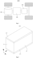
- Fig. 1 is a structural schematic diagram of a vehicle 1000 provided in some embodiments of the present application.
- the vehicle 1000 can be a fuel powered vehicle, a gas powered vehicle, or a new energy vehicle.
- the new energy vehicle can be a pure electric vehicle, a hybrid electric vehicle, or an extended range vehicle, etc.
- the interior of the vehicle 1000 is provided with a battery 100, which can be installed in the bottom, the front, or the rear of the vehicle 1000.
- the battery 100 can be used for the power supply of the vehicle 1000, for example, it can serve as the operating power supply of the vehicle 1000.
- the vehicle 1000 can further include a controller 200 and a motor 300, and the controller 200 is used to control the battery 100 to supply power to the motor 300, for example, for the starting, navigation, and operating power requirements of the vehicle 1000.
- the battery 100 can not only serve as the operating power source for the vehicle 1000, but also as the driving power source for the vehicle 1000, replacing or partially replacing the fuel or the natural gas to provide the driving power for the vehicle 1000.
- Fig. 2 is a structural schematic diagram of the battery 100 in some embodiments of the present application
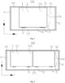
- Fig. 3 is a cross-sectional view of the electrode terminal 11 orientated toward the gap 3 between the battery cell 1 and the bottom cover 23 in some embodiments of the present application.
- the X direction in the figures is the first direction X
- the Y direction in the figures is the second direction Y
- the Z direction in the figures is the third direction Z. Any two of the first direction X, the second direction Y, and the third direction Z intersect with each other.
- the present application provides a battery 100, which includes a case 2 and a battery cell 1.
- the case 2 includes a case body 21, and a top cover 22 and a bottom cover 23 arranged opposite to each other along the first direction X on both sides of the case body 21.
- the battery cell 1 is arranged inside the case 2, and the battery cell 1 includes an electrode terminal 11. There is a gap 3 between the battery cell 1 and at least one of the bottom cover 23 and the case body 21, and the electrode terminal 11 is arranged toward the gap 3.
- the case body 21, the top cover 22, and the bottom cover 23 can jointly define an accommodation space for accommodating the battery cell 1, and the case 2 can to some extent avoid liquid or other foreign objects affecting the charging or discharging of the battery cell 1.
- the case body 21 can be integrally formed with the bottom cover 23 to be a hollow structure with an opening at one end, and the top cover 22 can be a plate-like structure.
- the top cover 22 covers and closes the open side of the hollow structure formed by the case body 21 and the bottom cover 23, so that the case body 21, the top cover 22, and the bottom cover 23 can jointly define the accommodation space.
- the top cover 22 can be integrally formed with a portion of the case body 21 to be a hollow structure with an opening at one end
- the bottom cover 23 can be integrally formed with another portion of the case body 21 to be a hollow structure with an opening at one end.
- the opening side of the hollow structure formed by the top cover 22 and a portion of the case body 21 covers and closes the opening side of the hollow structure formed by the bottom cover 23 and another portion of the case body 21, so that the case body 21, the top cover 22 and the bottom cover 23 can jointly define the accommodation space.
- the shape of the case 2 can be various, for example, cylindrical or cuboid.
- Multiple battery cells 1 can be connected in series, parallel, or hybrid. Hybrid connection refers to both series and parallel connection among multiple battery cells 1. Multiple battery cells 1 can be directly connected in series, parallel, or hybrid together, and then the whole composed of multiple battery cells 1 can be accommodated in the case 2. Of course, multiple battery cells 1 can also be connected in series, parallel, or hybrid to form a modular form of the battery 100. The modular of the multiple battery 100 can then be connected in series, parallel, or hybrid to form a whole and accommodated in the case 2.
- the battery 100 can further include other structures, for example, the battery 100 can further include other structures.
- the battery 100 can further include a busbar (not shown in the figures), which is used to achieve electrical connection between multiple battery cells 1.
- the types of battery cell 1 can be various.
- the battery cell 1 can be lithium ion secondary battery cell 1, lithium ion primary battery cell 1, lithium sulfur battery cell 1, sodium lithium ion battery cell 1, sodium ion battery cell 1, or magnesium ion battery cell 1, etc.
- the shape of battery cell 1 can be various, for example, cylindrical, flat, cuboid, or other shapes.
- the electrode terminal 11 is used to output or input electrical energy from or into the battery cell 1.
- the electrode terminal 11 can be used for electrical connection to the electrode assembly of the battery cell 1 (not shown in the figures) to achieve output or input of electrical energy from or into the battery cell 1.
- the electrode terminal 11 can orientate toward the gap 3 between the battery cell 1 and the bottom cover 23, and/or the electrode terminal 11 can orientate toward the gap 3 between the battery cell 1 and the case body 21.
- the battery 100 includes a case 2 and a battery cell 1.
- the case 2 includes a case body 21 and a top cover 22 and a bottom cover 23 arranged opposite to each other along the first direction X on both sides of the case body 21.
- the case 2 can be used to accommodate the battery cell 1.
- the battery cell 1 is located inside the case 2, and there is a gap 3 between the battery cell 1 and at least one of the bottom cover 23 and the case body 21.
- the case body 21 can play a role of cushioning the collision, making it less likely for the battery cell to collide with the case 2, thus improving the safety performance of the battery 100.
- the battery cell 1 has an electrode terminal 11 for inputting or outputting current.
- the electrode terminal 11 is arranged toward the gap 3, so that the gap 3 used for cushioning collisions within the battery 100 can also serve as a reserved space for electrical safety between the electrode terminal 11 and the case 2, thereby improving the space utilization rate in the battery 100 and making the structure of the battery 100 more compact.
- the gap 3 includes a first gap 31 between the battery cell 1 and the bottom cover 23, with the electrode terminal 11 orientated toward the first gap 31.
- the battery cell 1 further includes a bottom 12 arranged opposite to the electrode terminal 11 in the first direction X, and the bottom 12 is connected to the top cover 22.
- the size of the first gap 31 can be set according to the specific structure of the battery cell 1 and the specific structure of the case 2, so that the first gap 31 can cushion the collision between the battery cell 1 and the bottom cover 23, and make the structure of the battery 100 more compact.
- the first gap 31 between battery cell 1 and bottom cover 23 can refer to the gap 3 between the electrode terminal 11 of battery cell 1 and the bottom cover 23.
- the first gap 31 may be greater than or equal to 7mm.
- the bottom 12 of the battery cell 1 can be connected with the top cover 22 through adhesive material or welded with the top cover 22. In some other embodiments, the bottom 12 of the battery cell 1 can be connected to the top cover 22 through bolts.
- the first gap 31 can cushion the collision between the battery cell 1 and the bottom cover 23 when the battery 100 is impacted by the external force, thereby improving the safety performance of the battery 100.
- the first gap 31 for cushioning the collision between the battery cell 1 and the bottom cover 23 in battery 100 can also serve as a reserved space for electrical safety between the electrode terminal 11 and the case 2, thereby improving the space utilization rate in battery 100 and making the structure of the battery 100 more compact.
- the top cover thickness T 1 of the top cover 22 and the bottom cover thickness T 2 of the bottom cover 23 satisfy the following relationship: 0.3 mm ⁇ T 1 + T 2 ⁇ 16.5mm.
- the structural strength of the case 2 is relatively small, and the case 2 is prone to deformation or even fracture.
- the sum of the top cover thickness T 1 and the bottom cover thickness T 2 is greater than 16.5mm, the top cover 22 and bottom cover 23 which are excessively thick can easily make the battery 100 have a larger volume and weight, which can lead to over design of the battery 100 easily.
- the top cover thickness T 1 can refer to the thickness at any location on the top cover 22, and the top cover thickness T 1 can also refer to the average thickness at multiple locations on the top cover 22. In some embodiments, the top cover thickness T 1 can refer to the minimum thickness possessed by the top cover 22. In other embodiments, the top cover thickness T 1 can refer to the average thickness of the entire top cover 22.
- the bottom cover thickness T 2 can refer to the thickness at any location on the bottom cover 23, and the bottom cover thickness T 2 can also refer to the average thickness at multiple locations on the bottom cover 23. In some embodiments, the bottom cover thickness T 2 can refer to the minimum thickness possessed by the bottom cover 23. In other embodiments, the bottom cover thickness T 2 can refer to the average thickness of the entire bottom cover 23.
- the top cover thickness T 1 can be greater than the bottom cover thickness T 2 , so that the top cover 22 connected to the bottom 12 of the battery cell 1 has a good structural strength.
- top cover thickness T 1 and the bottom cover thickness T 2 By reasonably setting the relationship between the top cover thickness T 1 and the bottom cover thickness T 2 , the top cover 22 and the bottom cover 23 are less likely to have excessive thickness while meeting the structural strength.
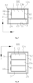
- Fig. 4 is a cross-sectional schematic diagram of the battery cell 1 arranged side by side in the second direction Y in some embodiments of the present application
- Fig. 5 is a cross-sectional schematic diagram of the battery cell 1 arranged side by side in the third direction Z in some embodiments of the present application.
- the battery cell 1 further includes a side wall 13 connected between the electrode terminal 11 and the bottom 12, wherein multiple battery cells 1 are arranged side by side in the second direction Y and/or the third direction Z, and the adjacent side walls 13 of the two battery cells 1 are connected with each other, and any two of the first direction X, the second direction Y, and the third direction Z intersect with each other.
- the electrode terminals 11 of the multiple battery cells 1 are all oriented toward the first gap 31, thereby further improving the space utilization rate in the battery 100 and making the structure of the battery 100 more compact.
- the side-by-side arrangement of multiple battery cells 1 also improves the structural strength of the battery 100.
- the number n . of the battery cells 1, the weight G of a single battery cell 1, the top cover thickness T 1 of the top cover 22, and the bottom cover thickness T 2 of the bottom cover 23 satisfy the following relationship: 0.1 ⁇ ( T 1 + T 2 )/ n * G ⁇ 16.5.
- the ratio of the sum of the top cover thickness T 1 and the bottom cover thickness T 2 to the total weight of all battery cells 1 is less than 0.1, the structural strength of the case 2 is relatively small, and the case 2 is susceptible to deformation or even fracture due to the weight of the battery cells 1.
- the top cover 22 and bottom cover 23 which are excessively thick can easily cause battery 100 to have a larger volume and weight, which leading to over design of the battery 100 easily.
- the unit of the weight G of the battery cell 1 is kg
- the unit of the top cover thickness T 1 and the bottom cover thickness T 2 is mm.
- the definition of the top cover thickness T 1 and the bottom cover thickness T 2 can be the same as the definition of the top cover thickness T 1 and the bottom cover thickness T 2 in the aforementioned embodiments.
- the weight G of single battery cell 1 By reasonably setting the number n of the battery cells 1, the weight G of single battery cell 1, and the relationship between the top cover thickness T 1 and the bottom cover thickness T 2 , the top cover 22 and bottom cover 23 are less likely to have excessive thickness, while meeting the structural strength for bearing the battery cell 1.
- Fig. 6 is a cross-sectional schematic diagram of the electrode terminal 11 orientated toward the gap 3 between the battery cell 1 and the case body 21 in some embodiments of the present application
- Fig. 7 is a cross-sectional schematic diagram of the electrode terminal 11 orientated toward the gap 3 between the battery cell 1 and the case body 21 in some other embodiments of the present application.
- the gap 3 includes a second gap 32 between the battery cell 1 and the case body 21, with electrode terminal 11 orientating the second gap 32.
- the size of the second gap 32 can be set according to the specific structure of the battery cell 1 and the specific structure of the case 2, so that the second gap 32 can cushion the collision between the battery cell 1 and the case body 21, and the structure of battery 100 is more compact.
- the second gap 32 between the battery cell 1 and the case body 21 can refer to the gap 3 between the electrode terminal 11 of the battery cell 1 and the case body 21.
- the second gap 32 may be greater than or equal to 4mm.
- the electrode terminal 11 of the battery cell 1 can be arranged toward at least one of the second gaps 32.
- the side wall 13 of the battery cell 1 can be connected to the top cover 22, thereby limiting the movement of the battery cell 1 within the case 2 and improving the space utilization rate in the battery 100, making the structure of the battery 100 more compact.
- the second gap 32 can cushion the collision between the battery cell 1 and the case body 21 when the battery 100 is impacted by the external force, thereby improving the safety performance of the battery 100.
- the second gap 32 for cushioning the collision between the battery cell 1 and the case body in the battery 100 can also serve as a reserved space for electrical safety between the electrode terminal 11 and the case 2, thereby improving the space utilization rate inside the battery 100 and making the structure of the battery 100 more compact.
- the case 2 further includes a bottom plate 24 arranged between the top cover 22 and the bottom cover 23.
- the battery cell 1 further includes a bottom 12 opposite the electrode terminal 11 in the second direction Y and a side wall 13 connected between the electrode terminal 11 and the bottom 12.
- the side wall 13 is connected to the bottom plate 24, and the bottom plate 24 is spaced apart from the bottom cover 23.
- the first direction X intersects with the second direction Y
- the bottom plate 24 can be arranged parallel to the bottom cover 23 or the top cover 22, and the two ends of the bottom plate 24 in the second direction Y and/or the third direction Z can be connected to the case body 21.
- the distance between the bottom plate 24 and the bottom cover 23 may be slightly less than or equal to the size of the first gap 31.
- the side wall 13 of the battery cell 1 can be connected to the bottom plate 24 through adhesive material or welded to the bottom plate 24. In some other embodiments, the side wall 13 of the battery cell 1 can be connected to the bottom plate 24 through bolts.
- the side wall 13 of the battery cell 1 may include a large side wall 13a and a small side wall 13b, with the surface area of the large side wall 13a being greater than that of the small side wall 13b.
- the location where the side wall 13 of battery cell 1 and the bottom plate 24 connect can be reasonably selected according to the structure and the size of case 2 and the battery cell 1.
- the large side wall 13a of the battery cell 1 can be arranged to be connected to the bottom plate 24.
- the small side wall 13b of the battery cell 1 can be arranged to be connected to the bottom plate 24.
- the spacing distribution between the bottom plate 24 and the bottom cover 23 enables the space between the bottom plate 24 and the bottom cover 23 to cushion the collision between the battery cell 1 and the bottom cover 23, thereby improving the safety performance of the battery 100.
- the top cover thickness T 1 of the top cover 22 and the bottom plate thickness T 3 of the bottom plate 24 satisfy the following relationship: 0.3mm ⁇ T 1 + T 3 ⁇ 16.5mm.
- the structural strength of the case 2 is relatively small, and the case 2 is prone to deformation or even fracture.
- the sum of the top cover thickness T 1 and the bottom plate thickness T 3 is greater than 16.5mm, the top cover 22 and bottom plate 24 which are excessively thick can easily make the battery 100 have a larger volume and weight, which lead to over design of the battery 100 easily.
- the definition of the top cover thickness T 1 can be the same as the definition of the top cover thickness T 1 in the aforementioned embodiments.
- the bottom plate thickness T 3 can refer to the thickness at any location on the bottom plate 24, and the bottom plate thickness T 3 can also refer to the average thickness at multiple locations on the bottom plate 24. In some embodiments, the bottom plate thickness T 3 can refer to the minimum thickness possessed by the bottom plate 24. In some other embodiments, the bottom plate thickness T 3 can refer to the average thickness of the entire bottom plate 24.
- the bottom plate thickness T 3 can be greater than the top cover thickness T 1 , so that the bottom plate 24 for supporting the battery cell 1 has a good structural strength.
- the top cover 22 and the bottom plate 24 are less likely to have excessive thickness, while meeting the structural strength.
- Fig. 8 is a cross-sectional schematic diagram of the battery cells 1 arranged side by side in the first direction X in some embodiments of the present application
- Fig. 9 is a cross-sectional schematic diagram of the battery cells 1 arranged side by side in the third direction Z in some other embodiments of the present application.
- multiple battery cells 1 are arranged side by side along the first direction X and/or the third direction Z, the side walls 13 of the two adjacent battery cells 1 are connected with each other, and any two of the first direction X, second direction Y, and third direction Z intersects with each other.
- the large side walls 13a and/or the small side walls 13b of the two adjacent battery cells 1 can be correspondingly arranged to be connected with each other according to the structure and the size of the case 2 and the battery cell 1.
- the large side wall 13a of the battery cell 1 on a side close to the bottom plate 24 can be arranged to be connected to the bottom plate 24, and the large side walls 13a of the two adjacent battery cells 1 can be arranged to be connected with each other, so that the battery cell 1 and the bottom plate 24 have a large stress area therebetween, thereby improving the structural stability inside the battery 100.
- the small side walls 13b of the battery cells 1 can be arranged to be connected to the bottom plate 24, and the large side walls 13a of the two adjacent battery cells 1 can be arranged to be connected with each other, so that the two adjacent battery cells 1 have a large contact area therebetween, thereby improving the structural stability inside the battery 100.
- the electrode terminals 11 of the multiple battery cells 1 are all oriented toward the second gap 32, thereby further improving the space utilization rate in the battery 100 and making the structure of the battery 100 more compact.
- the side-by-side arrangement of multiple battery cells 1 also improves the structural strength of the battery 100.
- the number n of battery cells 1, the weight G of a single battery cell 1, the top cover thickness T 1 of the top cover 22, and the bottom plate thickness T 3 of the bottom plate 24 satisfy the following relationship: 0.1 ⁇ ( T 1 + T 3 )/ n * G ⁇ 16.5.
- the ratio of the sum of the top cover thickness T 1 and the bottom plate thickness T 3 to the total weight of all battery cells 1 is less than 0.1, the structural strength of case 2 is relatively small, and the case 2 is susceptible to deformation or even fracture due to the weight of the battery cells 1.
- the ratio of the sum of the top cover thickness T 1 and the bottom plate thickness T 3 to the total weight of all battery cells 1 is greater than 16.5, the top cover 22 and bottom plate 24 which are excessively thick can easily cause the battery 100 to have a larger volume and weight, which leads to over design of battery 100 easily.
- the unit of the weight G of the battery cell 1 is kg
- the unit of the top cover thickness T 1 and the bottom plate thickness T 3 is mm.
- the definition of the top cover thickness T 1 and the bottom plate thickness T 3 can be the same as the definition of the top cover thickness T 1 and the bottom plate thickness T 3 in the aforementioned embodiments.
- the weight G of a single battery cell 1 By reasonably setting the number n of battery cells 1, the weight G of a single battery cell 1, and the relationship between the top cover thickness T 1 and the bottom plate thickness T 3 , the top cover 22 and the bottom plate 24 are less likely to have excessive thickness, while meeting the structural strength for bearing the battery cell 1.
- a buffer component (not shown in the figures) is filled between the top cover 22 and the bottom cover 23 for providing cushioning when the battery 100 is impacted.
- the buffer component can be a foamed material.
- the buffer component can be a foamed polyurethane or melamine foam.
- the buffer component when the electrode terminal 11 orients toward the first gap 31, the buffer component can be filled between the electrode terminal 11 and the bottom cover 23, so that the buffer component can be used to cushion the collision between the electrode terminal 11 and the bottom cover 23.
- the buffer component when the electrode terminal 11 orients toward the second gap 32, the buffer component can be filled between the bottom plate 24 and the bottom cover 23, so that the buffer component can be used to cushion the collision between the bottom plate 24 and the bottom cover 23.
- a buffer component may also be filled between the battery cell 1 and the case body 21, so that the buffer component can be used to cushion collision between the battery cell 1 and the case body 21.
- the collision resistance of the battery 100 is improved.
- the number n of the battery cells 1 is less than or equal to 10.
- the case 2 does not need to bear excessive weight of battery cells 1, so that the required volume of the case 2 does not need to be too large, thereby improving the structural utilization rate of the battery 100.
- the further some embodiments of the present application further provide an electricity consuming apparatus, which includes the battery 100 in any of the above embodiments for providing electrical energy.
- a battery 100 which includes a case 2 and a battery cell 1.
- the case 2 includes a case body 21, and a top cover 22 and a bottom cover 23 arranged opposite to each other in the first direction X on both sides of the case body 21.
- the battery cell 1 is arranged inside the case 2 and includes an electrode terminal 11 and a bottom 12 arranged opposite to each other, as well as a side wall 13 connected between the electrode terminal 11 and the bottom 12.
- the battery cell 1 When the battery cell 1 is arranged toward the first gap 31, multiple battery cells 1 are arranged side by side along the second direction Y and/or the third direction Z, and the bottom 12 of the battery cell 1 is connected to the top cover 22 of the case 2.
- a buffer material is filled between the electrode terminal 11 and the bottom cover 23.
- the number n of battery cells 1, the weight G of a single battery cell 1, the top cover thickness T 1 of the top cover 22, and the bottom cover thickness T 2 of the bottom cover 23 meet the following relationship: 0.1 ⁇ ( T 1 + T 2 )/ n * G ⁇ 16.5, wherein the number n of the battery cells 1 is less than or equal to 10.
- the case 2 When the battery cell 1 is arranged toward the second gap 32, multiple battery cells 1 are arranged side by side along the first direction X and/or the third direction Z, and the case 2 further has a bottom plate 24 arranged between the top cover 22 and the bottom cover 23.
- the side wall 13 of the battery cell 1 close to the side of the bottom plate 24 is connected to the bottom plate 24, and a buffer material is filled between the bottom plate 24 and the bottom cover 23.
- the number n of the battery cells 1, the weight G of a single battery cell 1, the top cover thickness T 1 of the top cover 22 and the bottom plate thickness T 3 of the bottom plate 24 meet the following relationship: 0.1 ⁇ ( T 1 + T 3 )/ n * G ⁇ 16.5, wherein the number n of battery cells 1 is less than or equal to 10.
Landscapes
- Chemical & Material Sciences (AREA)
- Chemical Kinetics & Catalysis (AREA)
- Electrochemistry (AREA)
- General Chemical & Material Sciences (AREA)
- Engineering & Computer Science (AREA)
- Aviation & Aerospace Engineering (AREA)
- Battery Mounting, Suspending (AREA)
- Sealing Battery Cases Or Jackets (AREA)
Abstract
Description
- The present application relates to the field of battery technology, particularly a battery and an electricity consuming apparatus.
- With the promotion of the concept of energy conservation and emission reduction, there are more and more fields using electricity as driving energy. Therefore, the demand for batteries in various fields is also increasing, and the development of battery technology is becoming increasingly important for the development of other fields.
- In most existing batteries, a certain reserved space is required between the case of the battery and the battery cell accommodated in the case to meet electrical safety. However, the arrangement of the reserved space results in poor utilization rate of the space inside the case, which in turn makes the structure of the battery not compact enough.
- In view of the above issue, the present application provides a battery and an electricity consuming apparatus, which has a high utilization rate of internal space and a relatively compact structure.
- In a first aspect, the embodiments of the present application provide a battery, which includes a case and a battery cell. The case includes a case body, and a top cover and a bottom cover arranged opposite to each other along a first direction on two sides of the case body; the battery cell is arranged inside the case, and the battery cell includes an electrode terminal. A gap is arranged between the battery cell and at least one of the bottom cover and the case body, and the electrode terminal is arranged toward the gap.
- In the technical solutions of some embodiments of the present application, the battery includes a case and a battery cell. The case includes a case body, and a top cover and a bottom cover arranged opposite to each other in the first direction on two sides of the case body. The case body can be used to accommodate the battery cell. The battery cell is arranged inside the case, and a gap is arranged between the battery cell and at least one of the bottom cover and the case body. When the battery is impacted by the external force, the gap between the battery cell and the bottom cover, the case body can play a role of cushioning collision, making it less likely for the battery cell to collide with the case body, thus improving the safety performance of the battery. The battery cell has an electrode terminal for inputting or outputting current. The electrode terminal is arranged toward the gap, so that the gap for cushioning collision within the battery can also serve as a reserved space for electrical safety between the electrode terminal and the case, thereby improving the space utilization rate inside the battery and making the structure of the battery more compact.
- According to the embodiments of the present application in the first aspect, the gap includes a first gap between the battery cell and the bottom cover, and the electrode terminal orientates toward the first gap. The battery cell further includes a bottom opposite to the electrode terminal in the first direction, and the bottom is connected to the top cover. By providing a first gap between the battery cell and the bottom cover, when the battery is impacted by the external force, the first gap can cushion the collision between the battery cell and the bottom cover, thereby improving the safety performance of the battery. By connecting the bottom of the battery cell to the top cover and orientating the electrode terminal toward the first gap, the first gap for cushioning the collision between the battery cell and the bottom cover in the battery can also serve as a reserved space for electrical safety between the electrode terminal and the case, thereby improving the space utilization rate inside the battery and making the structure of the battery more compact.
- According to any of the aforementioned embodiments of the present application in the first aspect, the top cover thickness T 1 of the top cover and the bottom cover thickness T 2 of the bottom cover satisfy the following relationship: 0.3mm ≤ T 1 + T 2 ≤ 16.5mm. By setting the relationship between the top cover thickness T 1 and the bottom cover thickness T 2 reasonably, the top cover and the bottom cover are less likely to have excessive thickness while meeting the structural strength.
- According to any of the aforementioned embodiments of the present application in the first aspect, the battery cell further includes a side wall connected between the electrode terminal and the bottom, wherein a plurality of battery cells are arranged side by side in a second direction and/or a third direction, and the side walls of two adjacent battery cells are connected with each other, and any two of the first direction, the second direction, and the third direction intersect with each other. By arranging the plurality of battery cells side by side in the second direction and/or the third direction, the electrode terminals of the plurality of battery cells orientate toward the first gap, thereby further improving the space utilization rate inside the battery, and making the structure of the battery more compact. The side-by-side arrangement of the plurality of battery cells also enhances the structural strength of the battery.
- According to any of the aforementioned embodiments of the present application in the first aspect, the number n of battery cells, the weight G of single battery cell, the top cover thickness T 1 of the top cover, and the bottom cover thickness T 2 of the bottom cover satisfy the following relationship: 0.1 ≤ (T 1 + T 2)/n * G ≤ 16.5. By reasonably setting the number n of battery cells, the weight G of single battery cell, and the relationship between the top cover thickness T 1 and the bottom cover thickness T 2, the top cover and bottom cover are less likely to have excessive thickness while meeting the structural strength for bearing the battery cell.
- According to any of the aforementioned embodiments of the present application in the first aspect, the gap includes a second gap between the battery cell and the case body, and the electrode terminal orientates toward the second gap. By providing a second gap between the battery cell and the case body, the second gap can cushion the collision between the battery cell and the case body when the battery is impacted by the external force, thereby improving the safety performance of the battery. By orienting the electrode terminal of the battery cell toward the second gap, the second gap for cushioning the collision between the battery cell and the case body can also serve as a reserved space for electrical safety between the electrode terminal and the case, thereby improving the space utilization rate inside the battery and making the structure of the battery more compact.
- According to any of the aforementioned embodiments of the present application in the first aspect, the case further includes a bottom plate arranged between the top cover and the bottom cover. The battery cell further includes a bottom opposite to the electrode terminal in the second direction, and a side wall connected between the electrode terminal and the bottom. The side wall is connected to the bottom plate, the bottom plate is spaced apart from the bottom cover, and the first direction intersects with the second direction. By providing a bottom plate between the top cover and bottom cover to support the battery cell, the spacing distribution of the bottom plate and bottom cover allows the space between the bottom plate and the bottom cover to cushion the collision between the battery cell and the bottom cover, thereby improving the safety performance of the battery.
- According to any of the aforementioned embodiments of the present application in the first aspect, the top cover thickness T 1 of the top cover and the bottom plate thickness T 3 of the bottom plate satisfy the following relationship: 0.3 mm ≤ T 1 + T 3 ≤ 16.5mm. By setting the relationship between the top cover thickness T 1 and the bottom plate thickness T 3 reasonably, the top cover and the bottom plate are less likely to have excessive thickness while meeting the structural strength.
- According to any of the aforementioned embodiments of the present application in the first aspect, a plurality of battery cells are arranged side by side in the first direction and/or the third direction, and the side walls of two adjacent battery cells are connected with each other, and any two of the first direction, the second direction, and the third direction intersect with each other. By arranging the plurality of battery cells side by side in the first direction and/or the third direction, the electrode terminals of the battery cells orientate toward the second gap, thereby further improving the space utilization rate inside the battery and making the structure of the battery more compact. The side-by-side arrangement of the plurality of battery cells also enhances the structural strength of the battery.
- According to any of the aforementioned embodiments of the present application in the first aspect, the number r. of battery cells, the weight G of single battery cell, the top cover thickness T 1 of the top cover, and the bottom plate thickness T 3 of the bottom plate satisfy the following relationship: 0.1 ≤ (T 1 + T 3)/n * G ≤ 16.5. By setting the number n of battery cells, the weight G of single battery cell, and the relationship between the top cover thickness T 1 and the bottom plate thickness T 3 reasonably, the top cover and bottom plate are less likely to have excessive thickness while meeting the structural strength for bearing the battery cell.
- According to any of the aforementioned embodiments of the present application in the first aspect, a buffer component for providing cushioning when the battery is impacted is filled between the top cover and the bottom cover. By providing a buffer component between the top cover and the bottom cover, the collision resistance of the battery is improved.
- According to any of the aforementioned embodiments of the present application in the first aspect, the number of battery cells is less than or equal to 10. By setting a reasonable number of battery cells, the case does not need to bear excessive weight of battery cells, so that the volume required by the case does not need to be too large, thereby improving the structural utilization rate of the battery.
- The embodiments of the present application in the second aspect provide an electricity consuming apparatus, which includes the battery in any of the above embodiments, and the battery is used to provide electrical energy.
- In order to provide a clearer explanation of the technical solution of the embodiments of the present application, a brief introduction will be given to the accompanying drawings required in the embodiments of the present application. It is evident that the accompanying drawings described below are only some embodiments of the present application. For the skilled person in the art, other accompanying drawings can be obtained based on the drawings without any creative effort.
-
Fig. 1 is a structural schematic diagram of a vehicle according to some embodiments of the present application; -
Fig. 2 is a structural schematic diagram of a battery in some embodiments of the present application; -
Fig. 3 is a cross-sectional schematic diagram of the electrode terminal orientated toward the gap between the battery cell and the bottom cover in some embodiments of the present application; -
Fig. 4 is a cross-sectional schematic diagram of battery cells arranged side by side in the second direction in some embodiments of the present application; -
Fig. 5 is a cross-sectional schematic diagram of battery cells arranged side by side in the third direction in some embodiments of the present application; -
Fig. 6 is a cross-sectional schematic diagram of the electrode terminal orientated toward the gap between the battery cell and the case body in some embodiments of the present application; -
Fig. 7 is a cross-sectional schematic diagram of the electrode terminal orientated toward the gap between the battery cell and the case body in some other embodiments of the present application; -
Fig. 8 is a cross-sectional schematic diagram of battery cells arranged side by side in the first direction in some embodiments of the present application; -
Fig. 9 is a cross-sectional schematic diagram of battery cells arranged side by side in the third direction in some other embodiments of the present application. - In the accompanying drawings, the drawings are not drawn to the actual scale.
- The description of the reference signs:
-
Vehicle 1000; -
Battery 100;Controller 200;Motor 300; - Battery cell 1;
Electrode terminal 11;Bottom 12;Side wall 13;Large sidewall 13a;Small sidewall 13b; -
Case 2;Case body 21;Top cover 22;Bottom cover 23;Bottom plate 24; -
Gap 3;First gap 31;Second gap 32; - First direction X;
- Second direction Y;
- Third direction Z.
- The following will provide a further detailed description of the embodiments of the present application in conjunction with the accompanying drawings and embodiments. The detailed description and accompanying drawings of the following embodiments are used to exemplify the principles of the present application, but cannot be used to limit the scope of the present application, that is, the present application is not limited to the described embodiments.
- In the description of the present application, it should be noted that unless otherwise specified, "multiple" means two or more; the orientation or positional relationship indicated by the terms "up", "down", "left", "right", "inside", "outside" is only for the convenience of describing and simplifying the present application, rather than indicating or implying that the device or component referred to must have a specific orientation, be constructed and operated in a specific orientation, and therefore cannot be understood as a limitation to the present application. In addition, the terms "first", "second", "third", etc. are only used for the purpose of the description and cannot be understood as indicating or implying relative importance. 'Vertical' is not limited to being strictly vertical, but allows an error within the allowable range. 'Parallel' is not limited to being strictly parallel, but allows an error within the allowable range.
- The directional words appearing in the following description are all the directions shown in the figures and do not limit the specific structure of the present application. In the description of the present application, it should be noted that unless otherwise specified and limited, the terms "install", "connected with", and "connect" should be broadly understood. For example, they can be fixed connection, detachable connection, or integrated connection; they can be directly connected, or indirectly connected through an intermediate medium, or they can be communicated between interiors of the two components. For the skilled person in the art, the specific meanings of the above terms in the present application can be understood based on specific circumstances.
- At present, based on the development of the market situation, the application of power battery is becoming increasingly widespread. Power battery is not only used in energy storage power systems such as hydropower, firepower, wind power, and solar power plant, but also widely used in electric vehicle such as electric bicycle, electric motorcycle, and electric automobile, as well as in various fields such as military equipment and aerospace. With the continuous expansion of the application field of power battery, its market demand is also constantly expanding.
- The inventors find that with the development of battery technology, people increasingly hope that the battery has a more compact structure. In most existing battery, a certain reserved space is often required between the electrode terminal of the battery cell and the case to meet the electrical safety of the battery. Due to the fact that the electrode terminal of the battery cell often faces the top cover of the case, the reserved space is often disposed between the battery cell and the top cover of the case, and gaps are required for cushioning collisions in multiple directions between the battery cell and the case. Therefore, the separate arrangement of the gaps for cushioning collisions and the reserved space results in poor utilization rate of space inside the case, which in turn leads to an insufficiently compact battery structure.
- In order to improve the utilization rate of the internal space of the battery so that the battery has a relatively compact structure, the applicant reached and found that the gap used for cushioning collisions in the battery can be disposed as the reserved space required for electrical safety between the electrode terminal and the case.
- For example, the case includes a case body and a bottom cover, and the gap between the battery cell and the case body or between the battery cell and the bottom cover is disposed as the reserved space required for electrical safety between the electrode terminal and the case body, with the electrode terminal orientated toward the gap.
- In such a battery, when the battery is impacted by the external force, the gap between the battery cell and the case body or between the battery cell and the bottom cover can play a role of cushioning the collision. Orienting the electrode terminal toward the gap between the battery cell and the case body or between the battery cell and the bottom cover allows the gap used for cushioning collisions within the battery to also serve as a reserved space for electrical safety between the electrode terminal and the case, thereby improving the space utilization rate in the battery and making the structure of the battery more compact.
- The battery mentioned in the embodiments of the present application refers to a single physical module that includes one or more battery cells to provide higher voltage and capacity. For example, the battery mentioned in the present application may include battery module or battery pack, etc. Battery generally include a case used to encapsulate one or more battery cells and the case can prevent liquid or other foreign objects from affecting the charging or discharging of the battery cell. This type of battery is suitable for various electricity consuming apparatuses that use batteries, such as mobile phones, portable devices, laptops, battery cars, electric toys, electric tools, electric vehicles, ships and spacecrafts. For example, the spacecrafts include airplanes, rockets, space shuttles, and spacecrafts, etc. The battery is used to provide electrical energy for the aforementioned electricity consuming apparatus.
- The electricity consuming apparatus provided in some embodiments of the present application can be vehicles, mobile phones, portable devices, laptops, ships, spacecrafts, electric toys, electric tools, and so on. The vehicle can be a fuel powered vehicle, a gas powered vehicle, or a new energy vehicle. The new energy vehicle can be a pure electric vehicle, a hybrid electric vehicle, or an extended range vehicle, etc. The spacecraft includes an airplane, a rocket, a space shuttle, and a spacecraft, among others. The electric toys include fixed or mobile electric toys, such as a game console, an electric car toy, an electric boat toy, and an electric airplane toy. The electric tools include metal cutting electric tools, grinding electric tools, assembly electric tools, and railway electric tools, such as an electric drill, an electric grinder, an electric wrench, an electric screwdriver, an electric hammer, an impact drill, a concrete vibrator, and an electric planer.
- It should be understood that the technical solution described in the embodiments of present application is not only applicable to the battery and the electricity consuming apparatus described above, but can also be applicable to all other batteries including the case and the electricity consuming apparatuses using the battery. However, for the sake of simplicity, the following embodiments are explained taking the electric vehicle as an example.
- Please refer to
Fig. 1 , which is a structural schematic diagram of avehicle 1000 provided in some embodiments of the present application. Thevehicle 1000 can be a fuel powered vehicle, a gas powered vehicle, or a new energy vehicle. The new energy vehicle can be a pure electric vehicle, a hybrid electric vehicle, or an extended range vehicle, etc. The interior of thevehicle 1000 is provided with abattery 100, which can be installed in the bottom, the front, or the rear of thevehicle 1000. Thebattery 100 can be used for the power supply of thevehicle 1000, for example, it can serve as the operating power supply of thevehicle 1000. Thevehicle 1000 can further include acontroller 200 and amotor 300, and thecontroller 200 is used to control thebattery 100 to supply power to themotor 300, for example, for the starting, navigation, and operating power requirements of thevehicle 1000. - In some embodiments of present application, the
battery 100 can not only serve as the operating power source for thevehicle 1000, but also as the driving power source for thevehicle 1000, replacing or partially replacing the fuel or the natural gas to provide the driving power for thevehicle 1000. -
Fig. 2 is a structural schematic diagram of thebattery 100 in some embodiments of the present application, andFig. 3 is a cross-sectional view of theelectrode terminal 11 orientated toward thegap 3 between the battery cell 1 and thebottom cover 23 in some embodiments of the present application. The X direction in the figures is the first direction X, the Y direction in the figures is the second direction Y, and the Z direction in the figures is the third direction Z. Any two of the first direction X, the second direction Y, and the third direction Z intersect with each other. - As shown in
Figs 2 and3 , the present application provides abattery 100, which includes acase 2 and a battery cell 1. Thecase 2 includes acase body 21, and atop cover 22 and abottom cover 23 arranged opposite to each other along the first direction X on both sides of thecase body 21. The battery cell 1 is arranged inside thecase 2, and the battery cell 1 includes anelectrode terminal 11. There is agap 3 between the battery cell 1 and at least one of thebottom cover 23 and thecase body 21, and theelectrode terminal 11 is arranged toward thegap 3. - In some embodiments, the
case body 21, thetop cover 22, and thebottom cover 23 can jointly define an accommodation space for accommodating the battery cell 1, and thecase 2 can to some extent avoid liquid or other foreign objects affecting the charging or discharging of the battery cell 1. For example, thecase body 21 can be integrally formed with thebottom cover 23 to be a hollow structure with an opening at one end, and thetop cover 22 can be a plate-like structure. Thetop cover 22 covers and closes the open side of the hollow structure formed by thecase body 21 and thebottom cover 23, so that thecase body 21, thetop cover 22, and thebottom cover 23 can jointly define the accommodation space. For example, thetop cover 22 can be integrally formed with a portion of thecase body 21 to be a hollow structure with an opening at one end, and thebottom cover 23 can be integrally formed with another portion of thecase body 21 to be a hollow structure with an opening at one end. The opening side of the hollow structure formed by thetop cover 22 and a portion of thecase body 21 covers and closes the opening side of the hollow structure formed by thebottom cover 23 and another portion of thecase body 21, so that thecase body 21, thetop cover 22 and thebottom cover 23 can jointly define the accommodation space. In addition, the shape of thecase 2 can be various, for example, cylindrical or cuboid. - In some embodiments, there may be one or multiple battery cells 1 in the
battery 100. Multiple battery cells 1 can be connected in series, parallel, or hybrid. Hybrid connection refers to both series and parallel connection among multiple battery cells 1. Multiple battery cells 1 can be directly connected in series, parallel, or hybrid together, and then the whole composed of multiple battery cells 1 can be accommodated in thecase 2. Of course, multiple battery cells 1 can also be connected in series, parallel, or hybrid to form a modular form of thebattery 100. The modular of themultiple battery 100 can then be connected in series, parallel, or hybrid to form a whole and accommodated in thecase 2. Thebattery 100 can further include other structures, for example, thebattery 100 can further include other structures. For example, thebattery 100 can further include a busbar (not shown in the figures), which is used to achieve electrical connection between multiple battery cells 1. - In some embodiments, the types of battery cell 1 can be various. For example, the battery cell 1 can be lithium ion secondary battery cell 1, lithium ion primary battery cell 1, lithium sulfur battery cell 1, sodium lithium ion battery cell 1, sodium ion battery cell 1, or magnesium ion battery cell 1, etc. The shape of battery cell 1 can be various, for example, cylindrical, flat, cuboid, or other shapes.
- In some embodiments, the
electrode terminal 11 is used to output or input electrical energy from or into the battery cell 1. For example, theelectrode terminal 11 can be used for electrical connection to the electrode assembly of the battery cell 1 (not shown in the figures) to achieve output or input of electrical energy from or into the battery cell 1. - In some embodiments, there may be a
gap 3 between the battery cell 1 and thebottom cover 23 that can buffer collisions between the battery cell 1 and thebottom cover 23, or agap 3 between the battery cell 1 and thecase body 21 that can buffer collisions between the battery cell 1 and thecase body 21. In some other embodiments, there is agap 3 that can buffer collisions both between the battery cell 1 and thebottom cover 23 and between the battery cell 1 and thecase body 21. Theelectrode terminal 11 can orientate toward thegap 3 between the battery cell 1 and thebottom cover 23, and/or theelectrode terminal 11 can orientate toward thegap 3 between the battery cell 1 and thecase body 21. - In the technical solutions of some embodiments of the present application, the
battery 100 includes acase 2 and a battery cell 1. Thecase 2 includes acase body 21 and atop cover 22 and abottom cover 23 arranged opposite to each other along the first direction X on both sides of thecase body 21. Thecase 2 can be used to accommodate the battery cell 1. The battery cell 1 is located inside thecase 2, and there is agap 3 between the battery cell 1 and at least one of thebottom cover 23 and thecase body 21. When thebattery 100 is impacted by the external force, thegap 3 between the battery cell 1 and thebottom cover 23, thecase body 21 can play a role of cushioning the collision, making it less likely for the battery cell to collide with thecase 2, thus improving the safety performance of thebattery 100. The battery cell 1 has anelectrode terminal 11 for inputting or outputting current. Theelectrode terminal 11 is arranged toward thegap 3, so that thegap 3 used for cushioning collisions within thebattery 100 can also serve as a reserved space for electrical safety between theelectrode terminal 11 and thecase 2, thereby improving the space utilization rate in thebattery 100 and making the structure of thebattery 100 more compact. - Please refer to
Fig. 3 . In some embodiments, thegap 3 includes afirst gap 31 between the battery cell 1 and thebottom cover 23, with theelectrode terminal 11 orientated toward thefirst gap 31. The battery cell 1 further includes a bottom 12 arranged opposite to theelectrode terminal 11 in the first direction X, and the bottom 12 is connected to thetop cover 22. - The size of the
first gap 31 can be set according to the specific structure of the battery cell 1 and the specific structure of thecase 2, so that thefirst gap 31 can cushion the collision between the battery cell 1 and thebottom cover 23, and make the structure of thebattery 100 more compact. In some embodiments, thefirst gap 31 between battery cell 1 and bottom cover 23 can refer to thegap 3 between theelectrode terminal 11 of battery cell 1 and thebottom cover 23. In some embodiments, thefirst gap 31 may be greater than or equal to 7mm. - There are various ways to connect the bottom 12 of the battery cell 1 with the
top cover 22. In some embodiments, the bottom 12 of the battery cell 1 can be connected with thetop cover 22 through adhesive material or welded with thetop cover 22. In some other embodiments, the bottom 12 of the battery cell 1 can be connected to thetop cover 22 through bolts. - By providing a
first gap 31 between the battery cell 1 and thebottom cover 23, thefirst gap 31 can cushion the collision between the battery cell 1 and thebottom cover 23 when thebattery 100 is impacted by the external force, thereby improving the safety performance of thebattery 100. By connecting the bottom 12 of the battery cell 1 to thetop cover 22 and orientating theelectrode terminal 11 toward thefirst gap 31, thefirst gap 31 for cushioning the collision between the battery cell 1 and thebottom cover 23 inbattery 100 can also serve as a reserved space for electrical safety between theelectrode terminal 11 and thecase 2, thereby improving the space utilization rate inbattery 100 and making the structure of thebattery 100 more compact. - In some embodiments, the top cover thickness T 1 of the
top cover 22 and the bottom cover thickness T 2 of thebottom cover 23 satisfy the following relationship: 0.3mm ≤ T 1 + T 2 ≤ 16.5mm. When the sum of the top cover thickness T 1 and the bottom cover thickness T 2 is less than 0.3mm, the structural strength of thecase 2 is relatively small, and thecase 2 is prone to deformation or even fracture. When the sum of the top cover thickness T 1 and the bottom cover thickness T 2 is greater than 16.5mm, thetop cover 22 and bottom cover 23 which are excessively thick can easily make thebattery 100 have a larger volume and weight, which can lead to over design of thebattery 100 easily. - The top cover thickness T 1 can refer to the thickness at any location on the
top cover 22, and the top cover thickness T 1 can also refer to the average thickness at multiple locations on thetop cover 22. In some embodiments, the top cover thickness T 1 can refer to the minimum thickness possessed by thetop cover 22. In other embodiments, the top cover thickness T 1 can refer to the average thickness of the entiretop cover 22. - The bottom cover thickness T 2 can refer to the thickness at any location on the
bottom cover 23, and the bottom cover thickness T 2 can also refer to the average thickness at multiple locations on thebottom cover 23. In some embodiments, the bottom cover thickness T 2 can refer to the minimum thickness possessed by thebottom cover 23. In other embodiments, the bottom cover thickness T 2 can refer to the average thickness of theentire bottom cover 23. - In some embodiments, the top cover thickness T 1 can be greater than the bottom cover thickness T 2, so that the
top cover 22 connected to the bottom 12 of the battery cell 1 has a good structural strength. - By reasonably setting the relationship between the top cover thickness T 1 and the bottom cover thickness T 2, the
top cover 22 and thebottom cover 23 are less likely to have excessive thickness while meeting the structural strength. -
Fig. 4 is a cross-sectional schematic diagram of the battery cell 1 arranged side by side in the second direction Y in some embodiments of the present application, andFig. 5 is a cross-sectional schematic diagram of the battery cell 1 arranged side by side in the third direction Z in some embodiments of the present application. - As shown in
Figs. 4 and5 , in some embodiments, the battery cell 1 further includes aside wall 13 connected between theelectrode terminal 11 and the bottom 12, wherein multiple battery cells 1 are arranged side by side in the second direction Y and/or the third direction Z, and theadjacent side walls 13 of the two battery cells 1 are connected with each other, and any two of the first direction X, the second direction Y, and the third direction Z intersect with each other. - By arranging multiple battery cells 1 side by side in the second direction Y and/or the third direction Z, the
electrode terminals 11 of the multiple battery cells 1 are all oriented toward thefirst gap 31, thereby further improving the space utilization rate in thebattery 100 and making the structure of thebattery 100 more compact. The side-by-side arrangement of multiple battery cells 1 also improves the structural strength of thebattery 100. - In some embodiments, the number n. of the battery cells 1, the weight G of a single battery cell 1, the top cover thickness T 1 of the
top cover 22, and the bottom cover thickness T 2 of thebottom cover 23 satisfy the following relationship: 0.1 ≤ (T 1 + T 2)/n * G ≤ 16.5. When the ratio of the sum of the top cover thickness T 1 and the bottom cover thickness T 2 to the total weight of all battery cells 1 is less than 0.1, the structural strength of thecase 2 is relatively small, and thecase 2 is susceptible to deformation or even fracture due to the weight of the battery cells 1. When the ratio of the sum of the top cover thickness T 1 and the bottom cover thickness T 2 to the total weight of all battery cells 1 is greater than 16.5, thetop cover 22 and bottom cover 23 which are excessively thick can easily causebattery 100 to have a larger volume and weight, which leading to over design of thebattery 100 easily. - The unit of the weight G of the battery cell 1 is kg, and the unit of the top cover thickness T 1 and the bottom cover thickness T 2 is mm. Among them, the definition of the top cover thickness T 1 and the bottom cover thickness T 2 can be the same as the definition of the top cover thickness T 1 and the bottom cover thickness T 2 in the aforementioned embodiments.
- By reasonably setting the number n of the battery cells 1, the weight G of single battery cell 1, and the relationship between the top cover thickness T 1 and the bottom cover thickness T 2, the
top cover 22 andbottom cover 23 are less likely to have excessive thickness, while meeting the structural strength for bearing the battery cell 1. -
Fig. 6 is a cross-sectional schematic diagram of theelectrode terminal 11 orientated toward thegap 3 between the battery cell 1 and thecase body 21 in some embodiments of the present application, andFig. 7 is a cross-sectional schematic diagram of theelectrode terminal 11 orientated toward thegap 3 between the battery cell 1 and thecase body 21 in some other embodiments of the present application. - As shown in
Figs. 6 and7 , in some embodiments, thegap 3 includes asecond gap 32 between the battery cell 1 and thecase body 21, withelectrode terminal 11 orientating thesecond gap 32. - The size of the
second gap 32 can be set according to the specific structure of the battery cell 1 and the specific structure of thecase 2, so that thesecond gap 32 can cushion the collision between the battery cell 1 and thecase body 21, and the structure ofbattery 100 is more compact. In some embodiments, thesecond gap 32 between the battery cell 1 and thecase body 21 can refer to thegap 3 between theelectrode terminal 11 of the battery cell 1 and thecase body 21. In some embodiments, thesecond gap 32 may be greater than or equal to 4mm. - In some embodiments, there are
second gaps 32 between two sides of the battery cell 1 in the second direction Y and/or the third direction Z and thecase body 21, making it less likely for the battery cell 1 and thecase body 21 to collide with each other in multiple directions. In some embodiments, theelectrode terminal 11 of the battery cell 1 can be arranged toward at least one of thesecond gaps 32. - In some embodiments, when the
electrode terminal 11 of the battery cell 1 is arranged toward thesecond gap 32, theside wall 13 of the battery cell 1 can be connected to thetop cover 22, thereby limiting the movement of the battery cell 1 within thecase 2 and improving the space utilization rate in thebattery 100, making the structure of thebattery 100 more compact. - By providing a
second gap 32 between the battery cell 1 and thecase body 21, thesecond gap 32 can cushion the collision between the battery cell 1 and thecase body 21 when thebattery 100 is impacted by the external force, thereby improving the safety performance of thebattery 100. By orienting theelectrode terminal 11 of the battery cell 1 toward thesecond gap 32, thesecond gap 32 for cushioning the collision between the battery cell 1 and the case body in thebattery 100 can also serve as a reserved space for electrical safety between theelectrode terminal 11 and thecase 2, thereby improving the space utilization rate inside thebattery 100 and making the structure of thebattery 100 more compact. - Please continue to refer to
Figs. 6 and7 . In some embodiments, thecase 2 further includes abottom plate 24 arranged between thetop cover 22 and thebottom cover 23. The battery cell 1 further includes a bottom 12 opposite theelectrode terminal 11 in the second direction Y and aside wall 13 connected between theelectrode terminal 11 and the bottom 12. Theside wall 13 is connected to thebottom plate 24, and thebottom plate 24 is spaced apart from thebottom cover 23. The first direction X intersects with the second direction Y - In some embodiments, the
bottom plate 24 can be arranged parallel to thebottom cover 23 or thetop cover 22, and the two ends of thebottom plate 24 in the second direction Y and/or the third direction Z can be connected to thecase body 21. - In some embodiments, the distance between the
bottom plate 24 and thebottom cover 23 may be slightly less than or equal to the size of thefirst gap 31. - There can be various connection ways between the
side wall 13 of the battery cell 1 and thebottom plate 24. In some embodiments, theside wall 13 of the battery cell 1 can be connected to thebottom plate 24 through adhesive material or welded to thebottom plate 24. In some other embodiments, theside wall 13 of the battery cell 1 can be connected to thebottom plate 24 through bolts. - In some embodiments, the
side wall 13 of the battery cell 1 may include alarge side wall 13a and asmall side wall 13b, with the surface area of thelarge side wall 13a being greater than that of thesmall side wall 13b. The location where theside wall 13 of battery cell 1 and thebottom plate 24 connect can be reasonably selected according to the structure and the size ofcase 2 and the battery cell 1. In some embodiments, thelarge side wall 13a of the battery cell 1 can be arranged to be connected to thebottom plate 24. In some other embodiments, thesmall side wall 13b of the battery cell 1 can be arranged to be connected to thebottom plate 24. - By providing a
bottom plate 24 between thetop cover 22 and thebottom cover 23 to support the battery cell 1, the spacing distribution between thebottom plate 24 and thebottom cover 23 enables the space between thebottom plate 24 and thebottom cover 23 to cushion the collision between the battery cell 1 and thebottom cover 23, thereby improving the safety performance of thebattery 100. - In some embodiments, the top cover thickness T 1 of the
top cover 22 and the bottom plate thickness T 3 of thebottom plate 24 satisfy the following relationship: 0.3mm ≤ T 1 + T 3 ≤ 16.5mm. When the sum of the top cover thickness T 1 and the bottom plate thickness T 3 is less than 0.3mm, the structural strength of thecase 2 is relatively small, and thecase 2 is prone to deformation or even fracture. When the sum of the top cover thickness T 1 and the bottom plate thickness T 3 is greater than 16.5mm, thetop cover 22 andbottom plate 24 which are excessively thick can easily make thebattery 100 have a larger volume and weight, which lead to over design of thebattery 100 easily. - The definition of the top cover thickness T 1 can be the same as the definition of the top cover thickness T 1 in the aforementioned embodiments.
- The bottom plate thickness T 3 can refer to the thickness at any location on the
bottom plate 24, and the bottom plate thickness T 3 can also refer to the average thickness at multiple locations on thebottom plate 24. In some embodiments, the bottom plate thickness T 3 can refer to the minimum thickness possessed by thebottom plate 24. In some other embodiments, the bottom plate thickness T 3 can refer to the average thickness of theentire bottom plate 24. - In some embodiments, the bottom plate thickness T 3 can be greater than the top cover thickness T 1, so that the
bottom plate 24 for supporting the battery cell 1 has a good structural strength. - By setting the relationship between the top cover thickness T 1 and the bottom plate thickness T 3 reasonably, the
top cover 22 and thebottom plate 24 are less likely to have excessive thickness, while meeting the structural strength. -
Fig. 8 is a cross-sectional schematic diagram of the battery cells 1 arranged side by side in the first direction X in some embodiments of the present application, andFig. 9 is a cross-sectional schematic diagram of the battery cells 1 arranged side by side in the third direction Z in some other embodiments of the present application. - As shown in
Figs. 8 and9 , in some embodiments, multiple battery cells 1 are arranged side by side along the first direction X and/or the third direction Z, theside walls 13 of the two adjacent battery cells 1 are connected with each other, and any two of the first direction X, second direction Y, and third direction Z intersects with each other. - In some embodiments, the
large side walls 13a and/or thesmall side walls 13b of the two adjacent battery cells 1 can be correspondingly arranged to be connected with each other according to the structure and the size of thecase 2 and the battery cell 1. - In some embodiments, when multiple battery cells 1 are arranged side by side along the first direction X, the
large side wall 13a of the battery cell 1 on a side close to thebottom plate 24 can be arranged to be connected to thebottom plate 24, and thelarge side walls 13a of the two adjacent battery cells 1 can be arranged to be connected with each other, so that the battery cell 1 and thebottom plate 24 have a large stress area therebetween, thereby improving the structural stability inside thebattery 100. - In some embodiments, when multiple battery cells 1 are arranged side by side along the third direction Z, the
small side walls 13b of the battery cells 1 can be arranged to be connected to thebottom plate 24, and thelarge side walls 13a of the two adjacent battery cells 1 can be arranged to be connected with each other, so that the two adjacent battery cells 1 have a large contact area therebetween, thereby improving the structural stability inside thebattery 100. - By arranging multiple battery cells 1 side by side along the first direction X and/or the third direction Z, the
electrode terminals 11 of the multiple battery cells 1 are all oriented toward thesecond gap 32, thereby further improving the space utilization rate in thebattery 100 and making the structure of thebattery 100 more compact. The side-by-side arrangement of multiple battery cells 1 also improves the structural strength of thebattery 100. - In some embodiments, the number n of battery cells 1, the weight G of a single battery cell 1, the top cover thickness T 1 of the
top cover 22, and the bottom plate thickness T 3 of thebottom plate 24 satisfy the following relationship: 0.1 ≤ (T 1 + T 3 )/n * G × 16.5. When the ratio of the sum of the top cover thickness T 1 and the bottom plate thickness T 3 to the total weight of all battery cells 1 is less than 0.1, the structural strength ofcase 2 is relatively small, and thecase 2 is susceptible to deformation or even fracture due to the weight of the battery cells 1. When the ratio of the sum of the top cover thickness T 1 and the bottom plate thickness T 3 to the total weight of all battery cells 1 is greater than 16.5, thetop cover 22 andbottom plate 24 which are excessively thick can easily cause thebattery 100 to have a larger volume and weight, which leads to over design ofbattery 100 easily. - The unit of the weight G of the battery cell 1 is kg, and the unit of the top cover thickness T 1 and the bottom plate thickness T 3 is mm. Among them, the definition of the top cover thickness T 1 and the bottom plate thickness T 3 can be the same as the definition of the top cover thickness T 1 and the bottom plate thickness T 3 in the aforementioned embodiments.
- By reasonably setting the number n of battery cells 1, the weight G of a single battery cell 1, and the relationship between the top cover thickness T 1 and the bottom plate thickness T 3, the
top cover 22 and thebottom plate 24 are less likely to have excessive thickness, while meeting the structural strength for bearing the battery cell 1. - In some embodiments, a buffer component (not shown in the figures) is filled between the
top cover 22 and thebottom cover 23 for providing cushioning when thebattery 100 is impacted. - The buffer component can be a foamed material. In some embodiments, the buffer component can be a foamed polyurethane or melamine foam.
- In some embodiments, when the
electrode terminal 11 orients toward thefirst gap 31, the buffer component can be filled between theelectrode terminal 11 and thebottom cover 23, so that the buffer component can be used to cushion the collision between theelectrode terminal 11 and thebottom cover 23. - In some other embodiments, when the
electrode terminal 11 orients toward thesecond gap 32, the buffer component can be filled between thebottom plate 24 and thebottom cover 23, so that the buffer component can be used to cushion the collision between thebottom plate 24 and thebottom cover 23. - In some embodiments, a buffer component may also be filled between the battery cell 1 and the
case body 21, so that the buffer component can be used to cushion collision between the battery cell 1 and thecase body 21. - By providing a buffer component that can provide cushioning between the
top cover 22 and thebottom cover 23, the collision resistance of thebattery 100 is improved. - In some embodiments, the number n of the battery cells 1 is less than or equal to 10.
- By setting a reasonable number of the battery cells 1, the
case 2 does not need to bear excessive weight of battery cells 1, so that the required volume of thecase 2 does not need to be too large, thereby improving the structural utilization rate of thebattery 100. - According to some embodiments of the present application, the further some embodiments of the present application further provide an electricity consuming apparatus, which includes the
battery 100 in any of the above embodiments for providing electrical energy. - According to some embodiments of the present application, there is provided a
battery 100, which includes acase 2 and a battery cell 1. Thecase 2 includes acase body 21, and atop cover 22 and abottom cover 23 arranged opposite to each other in the first direction X on both sides of thecase body 21. The battery cell 1 is arranged inside thecase 2 and includes anelectrode terminal 11 and a bottom 12 arranged opposite to each other, as well as aside wall 13 connected between theelectrode terminal 11 and the bottom 12. There is afirst gap 31 between the battery cell 1 and thebottom cover 23, there is asecond gap 32 between the battery cell 1 and thecase body 21, and theelectrode terminal 11 is arranged toward thefirst gap 31 and/or thesecond gap 32. When the battery cell 1 is arranged toward thefirst gap 31, multiple battery cells 1 are arranged side by side along the second direction Y and/or the third direction Z, and the bottom 12 of the battery cell 1 is connected to thetop cover 22 of thecase 2. A buffer material is filled between theelectrode terminal 11 and thebottom cover 23. The number n of battery cells 1, the weight G of a single battery cell 1, the top cover thickness T 1 of thetop cover 22, and the bottom cover thickness T 2 of thebottom cover 23 meet the following relationship: 0.1 ≤ (T 1 + T 2)/n * G ≤ 16.5, wherein the number n of the battery cells 1 is less than or equal to 10. When the battery cell 1 is arranged toward thesecond gap 32, multiple battery cells 1 are arranged side by side along the first direction X and/or the third direction Z, and thecase 2 further has abottom plate 24 arranged between thetop cover 22 and thebottom cover 23. Theside wall 13 of the battery cell 1 close to the side of thebottom plate 24 is connected to thebottom plate 24, and a buffer material is filled between thebottom plate 24 and thebottom cover 23. The number n of the battery cells 1, the weight G of a single battery cell 1, the top cover thickness T 1 of thetop cover 22 and the bottom plate thickness T 3 of thebottom plate 24 meet the following relationship: 0.1 ≤ (T 1 + T 3)/n * G ≤ 16.5, wherein the number n of battery cells 1 is less than or equal to 10. - The skilled person in the art should understand that the above embodiments are exemplary rather than restrictive. The different technical features that appear in different embodiments can be combined to achieve beneficial effects. On the basis of studying the accompanying drawings, specifications, and claims, the skilled person in the art should be able to understand and implement other variations of the disclosed embodiments. In the claims, the term "comprise" does not exclude other devices or steps. The articles "a", "an" and "the" are not intended to refer to only a singular entity, but include a description of a plurality of entities, and can be used interchangeably with "one" or "at least one". The terms "first" and "second" are used to indicate a name rather than any specific order. Any reference signs in the claims should not be construed as limiting the scope of protection. The functions of multiple parts appearing in the claims may be implemented by a separate hardware or software module. The appearance of certain technical features in different dependent claims does not mean that they cannot be combined to achieve beneficial effects.
Claims (13)
- A battery, comprising:a case (2) comprising a case body (21), and a top cover (22) and a bottom cover (23) arranged opposite to each other in a first direction on two sides of the case body (21); anda battery cell (1) arranged inside the case (2), the battery cell (1) comprising an electrode terminal (11),wherein a gap (3) is provided between the battery cell (1) and at least one of the bottom cover (23) and the case body (21), and the electrode terminal (11) is arranged toward the gap (3).
- The battery according to claim 1, wherein the gap (3) comprises a first gap (31) between the battery cell (1) and the bottom cover (23), the electrode terminal (11) orientates toward the first gap (31), the battery cell (1) further comprises a bottom (12) opposite to the electrode terminal (11) in the first direction, and the bottom (12) is connected to the top cover (22).
- The battery according to claim 2, wherein a top cover thickness T 1 of the top cover (22) and a bottom cover thickness T 2 of the bottom cover (23) satisfy the following relationship:

- The battery according to claim 2, wherein the battery cell (1) further comprises a side wall (13) connected between the electrode terminal (11) and the bottom (12),
wherein a plurality of battery cells (1) are arranged side by side along a second direction and/or a third direction, and the side walls (13) of two adjacent battery cells (1) are connected with each other, and any two of the first direction, the second direction, and the third direction intersect with each other. - The battery according to claim 4, wherein a number n of the battery cells (1), a weight G of a single battery cell (1), a top cover thickness T 1 of the top cover (22), and a bottom cover thickness T 2 of the bottom cover (23) satisfy the following relationship:

- The battery according to claim 1, wherein the gap (3) comprises a second gap (32) between the battery cell (1) and the case body (21), and the electrode terminal (11) is arranged toward the second gap (32).
- The battery according to claim 6, wherein the case (2) further comprises a bottom plate (24) arranged between the top cover (22) and the bottom cover (23), the battery cell (1) further comprises a bottom (12) opposite to the electrode terminal (11) in the second direction, and a side wall (13) connected between the electrode terminal (11) and the bottom (12), the side wall (13) is connected to the bottom plate (24), the bottom plate (24) and the bottom cover (23) are spaced apart, and the first direction intersects with the second direction.
- The battery according to claim 7, wherein a top cover thickness T 1 of the top cover (22) and a bottom plate thickness T 3 of the bottom plate (24) satisfy the following relationship:

- The battery according to claim 7, wherein a plurality of battery cells (1) are arranged side by side along the first direction and/or a third direction, the side walls (13) of two adjacent battery cells (1) are connected to each other, and any two of the first direction, the second direction and the third direction intersect with each other.
- The battery according to claim 9, wherein a number n of the battery cells (1), a weight G of a single battery cell (1), a top cover thickness T 1 of the top cover (22), and a bottom plate thickness T 3 of the bottom plate (24) satisfy the following relationship:

- The battery according to any one of claims 1 to 10, wherein a buffer component for providing cushioning when the battery is impacted is filled between the top cover (22) and the bottom cover (23).
- The battery according to any one of claims 1 to 10, wherein a number n of battery cells (1) is less than or equal to 10.
- An electricity consuming apparatus, comprising the battery according to any one of claims 1 to 12, the battery being configured for providing electrical energy.
Applications Claiming Priority (1)
| Application Number | Priority Date | Filing Date | Title |
|---|---|---|---|
| PCT/CN2022/123501 WO2024065769A1 (en) | 2022-09-30 | 2022-09-30 | Battery and electrical device |
Publications (2)
| Publication Number | Publication Date |
|---|---|
| EP4475328A1 true EP4475328A1 (en) | 2024-12-11 |
| EP4475328A4 EP4475328A4 (en) | 2025-04-09 |
Family
ID=90475715
Family Applications (1)
| Application Number | Title | Priority Date | Filing Date |
|---|---|---|---|
| EP22960382.4A Pending EP4475328A4 (en) | 2022-09-30 | 2022-09-30 | BATTERY AND ELECTRICAL DEVICE |
Country Status (4)
| Country | Link |
|---|---|
| US (1) | US20240429523A1 (en) |
| EP (1) | EP4475328A4 (en) |
| CN (1) | CN119111012A (en) |
| WO (1) | WO2024065769A1 (en) |
Family Cites Families (6)
| Publication number | Priority date | Publication date | Assignee | Title |
|---|---|---|---|---|
| PL3965216T3 (en) * | 2020-07-10 | 2023-06-19 | Contemporary Amperex Technology Co., Limited | BATTERY AND RELATED INSTRUMENTS, PREPARATION METHOD AND PREPARATION DEVICE |
| CN216903182U (en) * | 2021-11-03 | 2022-07-05 | 宁德时代新能源科技股份有限公司 | Battery box, integrated liquid cooling battery box, battery and power consumption device |
| CN216698608U (en) * | 2021-12-28 | 2022-06-07 | 宁德时代新能源科技股份有限公司 | Battery and electric equipment |
| CN217134495U (en) * | 2022-04-12 | 2022-08-05 | 宁德时代新能源科技股份有限公司 | Battery and electric device |
| CN217182349U (en) * | 2022-05-06 | 2022-08-12 | 中创新航科技股份有限公司 | Battery pack |
| CN115101880A (en) * | 2022-05-06 | 2022-09-23 | 中创新航科技股份有限公司 | Battery pack and vehicle |
-
2022
- 2022-09-30 WO PCT/CN2022/123501 patent/WO2024065769A1/en not_active Ceased
- 2022-09-30 EP EP22960382.4A patent/EP4475328A4/en active Pending
- 2022-09-30 CN CN202280095696.3A patent/CN119111012A/en active Pending
-
2024
- 2024-09-05 US US18/825,249 patent/US20240429523A1/en active Pending
Also Published As
| Publication number | Publication date |
|---|---|
| WO2024065769A1 (en) | 2024-04-04 |
| EP4475328A4 (en) | 2025-04-09 |
| US20240429523A1 (en) | 2024-12-26 |
| CN119111012A (en) | 2024-12-10 |
Similar Documents
| Publication | Publication Date | Title |
|---|---|---|
| CN217134495U (en) | Battery and electric device | |
| CN219203231U (en) | Battery and electricity utilization device | |
| CN217787321U (en) | Sampling assembly, battery and electric device | |
| CN220510172U (en) | Expansion beam, battery pack, energy storage system and electricity utilization device | |
| CN221176520U (en) | Battery and electric equipment | |
| CN219534714U (en) | Battery box, battery and power consumption device | |
| EP4510327A1 (en) | Battery cell, battery and electric device | |
| US20250192308A1 (en) | Battery box, battery and vehicle | |
| US20240429523A1 (en) | Battery and electricity consuming apparatus | |
| CN222168560U (en) | Battery devices and power devices | |
| CN220710527U (en) | Battery and electric equipment | |
| CN221176442U (en) | Bottom plate subassembly, box, battery and power consumption device | |
| CN220569775U (en) | Battery cells, batteries and electrical devices | |
| CN219145912U (en) | High-voltage box, battery and power utilization device | |
| WO2024036543A1 (en) | Battery and electrical device | |
| CN119096401A (en) | Batteries and electrical devices | |
| CN221102299U (en) | Batteries and electrical devices | |
| CN222927746U (en) | Battery cell, battery device and electricity utilization device | |
| CN116670904A (en) | Battery box, battery, bracket and electrical device | |
| CN223843075U (en) | Battery devices and electrical equipment | |
| CN222637462U (en) | Battery box, battery and power consumption device | |
| CN222637491U (en) | Batteries and electrical devices | |
| CN223785225U (en) | Battery devices and electrical equipment | |
| CN120581818B (en) | Battery device and electric equipment | |
| CN222637483U (en) | Batteries and electrical equipment |
Legal Events
| Date | Code | Title | Description |
|---|---|---|---|
| STAA | Information on the status of an ep patent application or granted ep patent |
Free format text: STATUS: THE INTERNATIONAL PUBLICATION HAS BEEN MADE |
|
| PUAI | Public reference made under article 153(3) epc to a published international application that has entered the european phase |
Free format text: ORIGINAL CODE: 0009012 |
|
| STAA | Information on the status of an ep patent application or granted ep patent |
Free format text: STATUS: REQUEST FOR EXAMINATION WAS MADE |
|
| 17P | Request for examination filed |
Effective date: 20240905 |
|
| AK | Designated contracting states |
Kind code of ref document: A1 Designated state(s): AL AT BE BG CH CY CZ DE DK EE ES FI FR GB GR HR HU IE IS IT LI LT LU LV MC MK MT NL NO PL PT RO RS SE SI SK SM TR |
|
| A4 | Supplementary search report drawn up and despatched |
Effective date: 20250312 |
|
| RIC1 | Information provided on ipc code assigned before grant |
Ipc: H01M 50/593 20210101ALI20250306BHEP Ipc: H01M 50/55 20210101ALI20250306BHEP Ipc: H01M 50/289 20210101ALI20250306BHEP Ipc: H01M 50/242 20210101ALI20250306BHEP Ipc: H01M 50/204 20210101ALI20250306BHEP Ipc: H01M 50/547 20210101AFI20250306BHEP |
|
| DAV | Request for validation of the european patent (deleted) | ||
| DAX | Request for extension of the european patent (deleted) |