EP4475322A1 - Battery module, battery pack, and battery system assembly - Google Patents
Battery module, battery pack, and battery system assembly Download PDFInfo
- Publication number
- EP4475322A1 EP4475322A1 EP24155668.7A EP24155668A EP4475322A1 EP 4475322 A1 EP4475322 A1 EP 4475322A1 EP 24155668 A EP24155668 A EP 24155668A EP 4475322 A1 EP4475322 A1 EP 4475322A1
- Authority
- EP
- European Patent Office
- Prior art keywords
- battery
- module
- battery module
- disposed
- battery cells
- Prior art date
- Legal status (The legal status is an assumption and is not a legal conclusion. Google has not performed a legal analysis and makes no representation as to the accuracy of the status listed.)
- Pending
Links
Images



Classifications
-
- H—ELECTRICITY
- H01—ELECTRIC ELEMENTS
- H01M—PROCESSES OR MEANS, e.g. BATTERIES, FOR THE DIRECT CONVERSION OF CHEMICAL ENERGY INTO ELECTRICAL ENERGY
- H01M50/00—Constructional details or processes of manufacture of the non-active parts of electrochemical cells other than fuel cells, e.g. hybrid cells
- H01M50/20—Mountings; Secondary casings or frames; Racks, modules or packs; Suspension devices; Shock absorbers; Transport or carrying devices; Holders
- H01M50/204—Racks, modules or packs for multiple batteries or multiple cells
- H01M50/207—Racks, modules or packs for multiple batteries or multiple cells characterised by their shape
- H01M50/209—Racks, modules or packs for multiple batteries or multiple cells characterised by their shape adapted for prismatic or rectangular cells
-
- H—ELECTRICITY
- H01—ELECTRIC ELEMENTS
- H01M—PROCESSES OR MEANS, e.g. BATTERIES, FOR THE DIRECT CONVERSION OF CHEMICAL ENERGY INTO ELECTRICAL ENERGY
- H01M50/00—Constructional details or processes of manufacture of the non-active parts of electrochemical cells other than fuel cells, e.g. hybrid cells
- H01M50/50—Current conducting connections for cells or batteries
- H01M50/502—Interconnectors for connecting terminals of adjacent batteries; Interconnectors for connecting cells outside a battery casing
-
- H—ELECTRICITY
- H01—ELECTRIC ELEMENTS
- H01M—PROCESSES OR MEANS, e.g. BATTERIES, FOR THE DIRECT CONVERSION OF CHEMICAL ENERGY INTO ELECTRICAL ENERGY
- H01M50/00—Constructional details or processes of manufacture of the non-active parts of electrochemical cells other than fuel cells, e.g. hybrid cells
- H01M50/50—Current conducting connections for cells or batteries
- H01M50/543—Terminals
- H01M50/552—Terminals characterised by their shape
- H01M50/553—Terminals adapted for prismatic, pouch or rectangular cells
-
- H—ELECTRICITY
- H01—ELECTRIC ELEMENTS
- H01M—PROCESSES OR MEANS, e.g. BATTERIES, FOR THE DIRECT CONVERSION OF CHEMICAL ENERGY INTO ELECTRICAL ENERGY
- H01M10/00—Secondary cells; Manufacture thereof
- H01M10/04—Construction or manufacture in general
- H01M10/0468—Compression means for stacks of electrodes and separators
-
- H—ELECTRICITY
- H01—ELECTRIC ELEMENTS
- H01M—PROCESSES OR MEANS, e.g. BATTERIES, FOR THE DIRECT CONVERSION OF CHEMICAL ENERGY INTO ELECTRICAL ENERGY
- H01M50/00—Constructional details or processes of manufacture of the non-active parts of electrochemical cells other than fuel cells, e.g. hybrid cells
- H01M50/20—Mountings; Secondary casings or frames; Racks, modules or packs; Suspension devices; Shock absorbers; Transport or carrying devices; Holders
- H01M50/289—Mountings; Secondary casings or frames; Racks, modules or packs; Suspension devices; Shock absorbers; Transport or carrying devices; Holders characterised by spacing elements or positioning means within frames, racks or packs
-
- H—ELECTRICITY
- H01—ELECTRIC ELEMENTS
- H01M—PROCESSES OR MEANS, e.g. BATTERIES, FOR THE DIRECT CONVERSION OF CHEMICAL ENERGY INTO ELECTRICAL ENERGY
- H01M50/00—Constructional details or processes of manufacture of the non-active parts of electrochemical cells other than fuel cells, e.g. hybrid cells
- H01M50/50—Current conducting connections for cells or batteries
- H01M50/502—Interconnectors for connecting terminals of adjacent batteries; Interconnectors for connecting cells outside a battery casing
- H01M50/503—Interconnectors for connecting terminals of adjacent batteries; Interconnectors for connecting cells outside a battery casing characterised by the shape of the interconnectors
-
- H—ELECTRICITY
- H01—ELECTRIC ELEMENTS
- H01M—PROCESSES OR MEANS, e.g. BATTERIES, FOR THE DIRECT CONVERSION OF CHEMICAL ENERGY INTO ELECTRICAL ENERGY
- H01M50/00—Constructional details or processes of manufacture of the non-active parts of electrochemical cells other than fuel cells, e.g. hybrid cells
- H01M50/50—Current conducting connections for cells or batteries
- H01M50/502—Interconnectors for connecting terminals of adjacent batteries; Interconnectors for connecting cells outside a battery casing
- H01M50/507—Interconnectors for connecting terminals of adjacent batteries; Interconnectors for connecting cells outside a battery casing comprising an arrangement of two or more busbars within a container structure, e.g. busbar modules
-
- H—ELECTRICITY
- H01—ELECTRIC ELEMENTS
- H01M—PROCESSES OR MEANS, e.g. BATTERIES, FOR THE DIRECT CONVERSION OF CHEMICAL ENERGY INTO ELECTRICAL ENERGY
- H01M50/00—Constructional details or processes of manufacture of the non-active parts of electrochemical cells other than fuel cells, e.g. hybrid cells
- H01M50/50—Current conducting connections for cells or batteries
- H01M50/502—Interconnectors for connecting terminals of adjacent batteries; Interconnectors for connecting cells outside a battery casing
- H01M50/509—Interconnectors for connecting terminals of adjacent batteries; Interconnectors for connecting cells outside a battery casing characterised by the type of connection, e.g. mixed connections
-
- H—ELECTRICITY
- H01—ELECTRIC ELEMENTS
- H01M—PROCESSES OR MEANS, e.g. BATTERIES, FOR THE DIRECT CONVERSION OF CHEMICAL ENERGY INTO ELECTRICAL ENERGY
- H01M50/00—Constructional details or processes of manufacture of the non-active parts of electrochemical cells other than fuel cells, e.g. hybrid cells
- H01M50/50—Current conducting connections for cells or batteries
- H01M50/543—Terminals
- H01M50/547—Terminals characterised by the disposition of the terminals on the cells
- H01M50/548—Terminals characterised by the disposition of the terminals on the cells on opposite sides of the cell
-
- H—ELECTRICITY
- H01—ELECTRIC ELEMENTS
- H01M—PROCESSES OR MEANS, e.g. BATTERIES, FOR THE DIRECT CONVERSION OF CHEMICAL ENERGY INTO ELECTRICAL ENERGY
- H01M50/00—Constructional details or processes of manufacture of the non-active parts of electrochemical cells other than fuel cells, e.g. hybrid cells
- H01M50/50—Current conducting connections for cells or batteries
- H01M50/543—Terminals
- H01M50/547—Terminals characterised by the disposition of the terminals on the cells
- H01M50/55—Terminals characterised by the disposition of the terminals on the cells on the same side of the cell
-
- H—ELECTRICITY
- H01—ELECTRIC ELEMENTS
- H01M—PROCESSES OR MEANS, e.g. BATTERIES, FOR THE DIRECT CONVERSION OF CHEMICAL ENERGY INTO ELECTRICAL ENERGY
- H01M50/00—Constructional details or processes of manufacture of the non-active parts of electrochemical cells other than fuel cells, e.g. hybrid cells
- H01M50/50—Current conducting connections for cells or batteries
- H01M50/572—Means for preventing undesired use or discharge
- H01M50/584—Means for preventing undesired use or discharge for preventing incorrect connections inside or outside the batteries
- H01M50/588—Means for preventing undesired use or discharge for preventing incorrect connections inside or outside the batteries outside the batteries, e.g. incorrect connections of terminals or busbars
-
- H—ELECTRICITY
- H01—ELECTRIC ELEMENTS
- H01M—PROCESSES OR MEANS, e.g. BATTERIES, FOR THE DIRECT CONVERSION OF CHEMICAL ENERGY INTO ELECTRICAL ENERGY
- H01M50/00—Constructional details or processes of manufacture of the non-active parts of electrochemical cells other than fuel cells, e.g. hybrid cells
- H01M50/50—Current conducting connections for cells or batteries
- H01M50/572—Means for preventing undesired use or discharge
- H01M50/584—Means for preventing undesired use or discharge for preventing incorrect connections inside or outside the batteries
- H01M50/59—Means for preventing undesired use or discharge for preventing incorrect connections inside or outside the batteries characterised by the protection means
- H01M50/593—Spacers; Insulating plates
-
- H—ELECTRICITY
- H01—ELECTRIC ELEMENTS
- H01M—PROCESSES OR MEANS, e.g. BATTERIES, FOR THE DIRECT CONVERSION OF CHEMICAL ENERGY INTO ELECTRICAL ENERGY
- H01M50/00—Constructional details or processes of manufacture of the non-active parts of electrochemical cells other than fuel cells, e.g. hybrid cells
- H01M50/50—Current conducting connections for cells or batteries
- H01M50/502—Interconnectors for connecting terminals of adjacent batteries; Interconnectors for connecting cells outside a battery casing
- H01M50/514—Methods for interconnecting adjacent batteries or cells
- H01M50/516—Methods for interconnecting adjacent batteries or cells by welding, soldering or brazing
-
- H—ELECTRICITY
- H01—ELECTRIC ELEMENTS
- H01M—PROCESSES OR MEANS, e.g. BATTERIES, FOR THE DIRECT CONVERSION OF CHEMICAL ENERGY INTO ELECTRICAL ENERGY
- H01M50/00—Constructional details or processes of manufacture of the non-active parts of electrochemical cells other than fuel cells, e.g. hybrid cells
- H01M50/50—Current conducting connections for cells or batteries
- H01M50/531—Electrode connections inside a battery casing
- H01M50/54—Connection of several leads or tabs of plate-like electrode stacks, e.g. electrode pole straps or bridges
-
- Y—GENERAL TAGGING OF NEW TECHNOLOGICAL DEVELOPMENTS; GENERAL TAGGING OF CROSS-SECTIONAL TECHNOLOGIES SPANNING OVER SEVERAL SECTIONS OF THE IPC; TECHNICAL SUBJECTS COVERED BY FORMER USPC CROSS-REFERENCE ART COLLECTIONS [XRACs] AND DIGESTS
- Y02—TECHNOLOGIES OR APPLICATIONS FOR MITIGATION OR ADAPTATION AGAINST CLIMATE CHANGE
- Y02E—REDUCTION OF GREENHOUSE GAS [GHG] EMISSIONS, RELATED TO ENERGY GENERATION, TRANSMISSION OR DISTRIBUTION
- Y02E60/00—Enabling technologies; Technologies with a potential or indirect contribution to GHG emissions mitigation
- Y02E60/10—Energy storage using batteries
Definitions
- the present invention relates to a battery module, and more specifically, to a battery system assembly including a battery pack in which a battery module is disposed.
- secondary batteries can be charged and discharged, and are used in not only small and high-tech electronic devices such as portable phones, notebook computers, and computers, but also power sources for energy storage systems (ESSs), electric vehicles, and hybrid vehicles.
- ESSs energy storage systems
- electric vehicles and hybrid vehicles.
- the secondary batteries widely used in the ESSs, the electric vehicles, and the like may be classified into lithium-ion batteries, lithium-polymer batteries, nickelcadmium batteries, nickel-hydrogen batteries, nickel-zinc batteries, and the like, and are repeatedly charged and discharged with an output voltage of approximately 25 V to 42 V per unit cell. Accordingly, when a higher output voltage and a higher power capacity are required, a plurality of battery cells are connected in series to form battery modules, or the battery modules are connected in series or parallel with additional other circuits to form battery packs.
- the present invention is directed to providing a battery module, a battery pack, and a battery system assembly in which a length of a pack busbar for electrically connecting battery packs is minimized to lower a weight of a product, reduce a material cost, and minimize heating, and since a passage of the pack busbar is not disposed above the battery module, an explosion caused by a short circuit between the pack busbar and a battery cell is prevented during a thermal runaway.
- a battery module including battery cells of which positive electrodes and negative electrodes which are formed at one end thereof are alternately stacked in a stacking direction, a pair of end plates coupled to both side ends of the stacked battery cells, and module busbars electrically connected to lead tabs provided on the battery cells, wherein, among the battery cells, battery cells disposed at both side ends of the battery module are disposed so that front ends and rear ends of the battery cells disposed at both side ends of the battery module have the same electrode, respectively.
- front ends of a pair of battery cells disposed at one side end of the battery module may have positive electrodes, and a rear end of a battery cell disposed on the other side end may have a negative electrode.
- a pair of battery cells disposed at an outer side of the battery module may be removed from among the battery cells, the front ends and the rear ends of the battery cells disposed at both side ends of the battery cells module have the same electrode, respectively, and the end plates may be formed to be thick.
- a battery module including battery cells of which positive electrodes and negative electrodes which are formed at one end portions thereof are alternately stacked in a stacking direction, a pair of end plates coupled to both side ends of the stacked battery cells, and module busbars electrically connected to lead tabs provided on the battery cells, wherein, among the battery cells, battery cells disposed at both side ends of the battery module are disposed so that front ends and rear ends of battery cells disposed at both side ends of the battery module have different electrodes, and an inner plate for electrical connection with the module busbars is disposed between the battery cells and the end plates.
- the inner plate may include insulating plates and a conductor which is disposed between the insulating plates and of which an upper end portion is in contact with each of the module busbars and a lower end portion is in contact with a pack busbar for electrical connection between battery packs.
- a protruding portion for preventing a short circuit may be formed to protrude from one surface of the insulating plate facing the battery cell.
- An extending portion which extends downward further than a lower end of the insulating plates to be exposed and is in contact with the pack busbar may be formed on the conductor, and the extending portion may be in contact with a gap filler disposed under the battery cell.
- a battery pack including a plurality of first battery modules which are stacked and coupled and a battery module stacked on and coupled to one side end of the first battery module, wherein the battery module includes a second battery module or third battery module in which a positive electrode and a negative electrode are formed at a front end and a rear end thereof.
- a battery system assembly wherein the second battery module and the third battery module are alternately disposed on both side ends of the first battery module in a front-rear direction, and the second battery module and the third battery module are electrically connected by a pack busbar.
- a positive electrode may be formed at a front left end, and a negative electrode may be is formed at a rear right end.
- a positive electrode may be formed at a front right end, and a negative electrode may be formed at a rear left end.
- first component when a first component is described as being formed or disposed “on” or “under” a second component, such a description includes both a case in which the two components are formed or disposed in direct contact with each other and a case in which one or more other components are interposed between the two components.
- first component when the first component is described as being formed “on or under” the second component, such a description may include a case in which the first component is formed at an upper side or a lower side with respect to the second component.
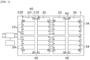
- FIG. 1 is a plan view illustrating a battery system assembly according to one embodiment of the present invention
- FIG. 2 is a side view illustrating the battery system assembly according to one embodiment of the present invention
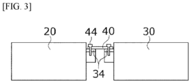
- FIG. 3 is a view illustrating a second battery module and a third battery module which are connected through a pack busbar according to one embodiment of the present invention
- FIG. 4 is a view illustrating a configuration of a battery pack according to one embodiment of the present invention
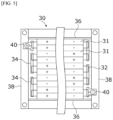
- FIG. 5 is a view illustrating a configuration of a third battery module according to one embodiment of the present invention.
- a battery module may include battery cells 31 of which positive electrodes and negative electrodes formed at one ends thereof are alternately stacked in a stacking direction, a pair of end plates 36 coupled to both side ends of the battery cells 31, and module busbars 34 electrically connected to lead tabs 32 provided on the battery cells 31, and, among the battery cells 31, the battery cells 31 disposed at both side ends of the battery module may be disposed so that front ends and rear ends thereof have the same electrode.
- a battery system assembly may include a case 1, and the case 1 may have a lower portion and a side portion.
- a case cover 2 may be coupled to an upper portion of the case 1.
- a plurality of battery packs 100 and 110 may be disposed in the case 1.
- the battery packs 100 and 110 may be two battery packs 100 and 110 having different battery module arrangements.
- the battery packs 100 and 110 three battery modules 10, 20, and 30 may be stacked and coupled.
- the battery modules 10, 20, and 30 may be provided as three battery modules 10, 20, and 30 and include first battery modules 10, second battery modules 20, and third battery modules 30.
- the battery packs 100 and 110 may include a first battery pack 100 and a second battery pack 110.
- the first battery module 10 may have a general structure, and a positive electrode and a negative electrode may be disposed on a front end or rear end thereof.
- a left side is referred to as the front end
- a right side is referred to as the rear end.
- the positive electrodes and the negative electrodes may be disposed at the front end
- the positive electrodes and the negative electrodes may be disposed at the rear end.
- the electrode arrangement of the first battery modules 10 may be disposed so that the positive electrodes and the negative electrodes are formed by alternating at the front end, the rear end, the front end, and the rear end of the first battery modules 10 disposed from the front end to the rear end.
- the number of the first battery modules 10 may be largest.
- the battery packs 100 and 110 may include four battery modules 10, 20, and 30, wherein the first battery modules 10 may be disposed in a central portion, and the second battery modules 20 and the third battery modules 30 may be disposed at a left end and a right end thereof, respectively.
- the reason why the second battery modules 20 and the third battery modules 30 are disposed at both side ends is to minimize lengths of pack busbars 40 by electrically connecting through the busbars 40 at only both ends. As such, when the length of the pack busbar 40 is minimized, a weight of a product can be reduced, a material cost can be reduced, and heating can be minimized.
- a passage of the pack busbars 40 is not disposed above the battery modules 10, 20, and 30, an explosion caused by a short circuit between the pack busbars 40 and the battery cells during a thermal runaway can be prevented.
- the positive electrodes and the negative electrodes of the second battery module 20 and the third battery module 30 may be formed at the front end and the rear end, respectively.
- the positive electrode may be formed at a front left end
- the negative electrode may be formed at a rear right end
- the positive electrode may be formed at a front right end
- the negative electrode may be formed at a rear left end.
- the positive electrodes and the negative electrodes may be electrically connected by the pack busbars 40.
- the negative electrode of a rear right end of the second battery module 20 and the positive electrode of a front right end of the third battery module 30 may be connected to the pack busbar 40, and the negative electrode of a rear left end of the third battery module 30 and the positive electrode of a front left end of the second battery module 20 may be connected to the pack busbar 40.
- the above-described second battery modules 20 and third battery modules 30 are alternately disposed along both side end of the first battery modules 10 which are mainly disposed, and actual electrical connection between the battery packs 100 and 110 may be made through connection between the second battery modules 20 and the third battery modules 30.
- the second battery module 20 and the third battery module 30 disposed at a front end may be formed so that the positive electrode or the negative electrode is positioned to be close to the first battery module 10 at the front end. This is for minimizing the length of the module busbar 34 when the second battery module 20 and the third battery module 30 are directly stacked on and electrically connected to the first battery module 10.
- the module busbars 34 may be connected to a front end or a rear end of the second battery module 20 and the third battery module 30, and the pack busbar 40 may be connected in contact with upper portions of the neighboring module busbars 34.
- the pack busbar 40 and the module busbars 34 may be fastened through fastening holes 44 passing through the pack busbar 40 and the module busbars 34.
- the battery packs 100 and 110 may be formed by stacking and coupling the first battery module 10, the second battery module 20, and the third battery module 30.
- the first battery pack 100 is formed by stacking three first battery modules 10 in a side surface direction and coupling the second battery module 20 to one side end portion
- the second battery pack 110 is formed by stacking three first battery modules 10 in a side surface direction and coupling the third battery module 30 to one side end portion.
- the second battery module 20 and the third battery module 30 may be turned to change positions of the front ends and the rear ends and stacked on one side end portions of the first battery modules 10.
- the second battery module 20 when the second battery module 20 is disposed at a left upper end, the second battery module 20 may not be disposed first at a left lower end and may be disposed next to the third battery module 30 in a state in which the second battery module 20 is turned to change positions of the front ends and the rear ends.
- the third battery module 30 will be described with reference to FIG. 5 .
- Components included in the third battery module 30 may be commonly included in the first battery module 10 and the second battery module 20.
- a plurality of battery cells 31 having positive electrodes or negative electrodes are stacked in both end portions of the third battery module 30.
- the plurality of battery cells 31 may be stacked in a side surface direction, and battery cells 31 having the same electrode arrangement structure may be formed as a pair of battery cells 31 so that electrodes of both end portions may be alternately disposed to have opposite positions when stacked.
- the pair of battery cells 31 of which the front ends have the positive electrodes and the rear ends have the negative electrodes
- the pair of battery cells 31 of which the front ends have the negative electrodes and the rear ends have the positive electrodes may be alternately disposed from a left side.
- the lead tabs 32 may be provided on both side ends of the pair of battery cells 31, and the module busbars 34 may be connected in contact with upper portions of the neighboring lead tabs 32.
- the end plates 36 are coupled to both side ends of the third battery module 30.
- cover assemblies 38 are coupled to a front end and a rear end of the third battery module 30 to cover the battery cells 31.
- the above-described third battery module 30 is formed by removing one battery cell 31 disposed at an outer side from the pair of battery cells 31 actually stacked and coupled to each other.
- the third battery module 30 one pair of battery cells 31 disposed at an outer side of the first battery module 10 in which five pairs of battery cells 31 are stacked are removed, and the end plate 36 is formed to be thick at a portion at which the one pair of battery cells 31 are removed.
- the positive electrodes and the negative electrodes are disposed at only the front end or the rear end, and thus, the length of the pack busbar 40 for electrical connection between the first battery modules 10 increases.
- the pair of battery cells 31 disposed at the outer side are removed, the positive electrodes and the negative electrodes may be formed on the front end and the rear end.
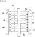
- FIG. 6 is a view illustrating a configuration of a third battery module according to another embodiment of the present invention
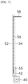
- FIG. 7 is a side view illustrating a structure of an inner plate of the third battery module according to another embodiment of the present invention
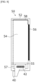
- FIG. 8 is a rear view illustrating the structure of the inner plate of the third battery module according to another embodiment of the present invention
- FIG. 9 is a view illustrating a module busbar in contact with a gap filler in the third battery module according to another embodiment of the present invention.
- a third battery module 30 uses the first battery module 10 described in the above-described embodiment without change and also uses an inner plate 50 to reduce a distance between electrodes of battery packs 100 and 110.
- the inner plate 50 may include a first insulating plate 52, a second insulating plate 54, a conductor 56 disposed between the first insulating plate 52 and the second insulating plate 54, and a pack busbar 40 electrically connected to the conductor 56.
- the first insulating plate 52 and the second insulating plate 54 may be formed as one plate.
- the first insulating plate 52 and the second insulating plate 54 may serve to insulate between an end plate 36 and the conductor 56 and be formed of a plastic material.
- a protruding portion 55 for preventing a short circuit between the pack busbar 40 and a battery cell 31 may be formed to protrude from a lower end portion of the second insulating plate 54 toward the battery cell 31.
- the protruding portion 55 does not need to be formed on only the lower end portion of the second insulating plate 54, and a plurality of protruding portions 55 may be vertically formed on one surface facing the battery cell 31.
- the conductor 56 may serve as a moving passage of an electrode and be formed of a metal material such as aluminum and copper.
- a contact portion 58 bent toward the battery cell 31 is formed on an upper end portion of the conductor 56 and is in contact with a module busbar 34.
- a lower end portion of the conductor 56 may be electrically connected to the pack busbar 40 through the module busbar 34 and the conductor 56 from the battery cell 31 because of being in contact with the pack busbar 40 as in the drawings.
- a welding portion 42 for connection with the conductor 56 may be formed on the pack busbar 40, and the pack busbar 40 may be electrically connected to the conductor 56 exposed downward through welding. Meanwhile, an extending portion 57 extending downward further than a lower end of the second insulating plate 54 is formed on the conductor 56, and the extending portion 57 is in contact with a gap filler 62 disposed under the battery cell 31.
- a cooling plate 60 is disposed under the battery cell 31.
- the cooling plate 60 serves to dissipate heat emitted from the battery cell 31.
- the gap filler 62 is applied between the battery cell 31 and the cooling plate 60 so that the heat generated by the battery cell 31 is transferred to the cooling plate 60.
- the gap filler 62 may be formed of polyurethane or silicon to which boron nitride (BN), aluminum nitride (AIN), silicon carbide (SiC), magnesium oxide (MgO), aluminum, or the like may be added.
- the gap filler 62 may extend to protrude toward each of the pack busbars 40 disposed at a front side and a rear side in order to transfer heat emitted from the pack busbar 40.
- the gap filler 62 formed as described above may be in direct contact with the extending portion 57 of the conductor 56 so that heat emitted from the module busbar 34 and the pack busbar 40 can be smoothly transferred to the cooling plate 60 through the gap filler 62.
- a weight of a product can be lowered, a material cost can be reduced, heating can be minimized, and since a passage of the pack busbar is not positioned above a battery module, an explosion caused by a short circuit between the pack busbar and a battery cell during a thermal runaway can be prevented.
Landscapes
- Chemical & Material Sciences (AREA)
- Chemical Kinetics & Catalysis (AREA)
- Electrochemistry (AREA)
- General Chemical & Material Sciences (AREA)
- Engineering & Computer Science (AREA)
- Manufacturing & Machinery (AREA)
- Battery Mounting, Suspending (AREA)
- Connection Of Batteries Or Terminals (AREA)
Abstract
Description
- This application claims priority to and the benefit of
Korean Patent Application No. 10-2023-0073266, filed on June 08, 2023 - The present invention relates to a battery module, and more specifically, to a battery system assembly including a battery pack in which a battery module is disposed.
- Unlike primary batteries which cannot be charged, secondary batteries can be charged and discharged, and are used in not only small and high-tech electronic devices such as portable phones, notebook computers, and computers, but also power sources for energy storage systems (ESSs), electric vehicles, and hybrid vehicles.
- The secondary batteries widely used in the ESSs, the electric vehicles, and the like may be classified into lithium-ion batteries, lithium-polymer batteries, nickelcadmium batteries, nickel-hydrogen batteries, nickel-zinc batteries, and the like, and are repeatedly charged and discharged with an output voltage of approximately 25 V to 42 V per unit cell. Accordingly, when a higher output voltage and a higher power capacity are required, a plurality of battery cells are connected in series to form battery modules, or the battery modules are connected in series or parallel with additional other circuits to form battery packs.
- However, when conventional standardized battery modules are used, there is a problem that an electrical connection passage of a busbar for connecting battery packs extends along a long way. That is, since the busbar is disposed over the battery packs, there are problems that a thickness of a battery increases, interference noise with the module is generated due to vibrations, the busbar is directly exposed to a flame during a thermal runaway, and the busbar functions as a heat diffusion passage between modules because an area thereof is increased.
- The present invention is directed to providing a battery module, a battery pack, and a battery system assembly in which a length of a pack busbar for electrically connecting battery packs is minimized to lower a weight of a product, reduce a material cost, and minimize heating, and since a passage of the pack busbar is not disposed above the battery module, an explosion caused by a short circuit between the pack busbar and a battery cell is prevented during a thermal runaway.
- Objectives to be solved by the present invention are not limited to the above-described objectives, and other objectives which are not described above will be clearly understood by those skilled in the art through the following description.
- According to an aspect of the present invention, there is provided a battery module including battery cells of which positive electrodes and negative electrodes which are formed at one end thereof are alternately stacked in a stacking direction, a pair of end plates coupled to both side ends of the stacked battery cells, and module busbars electrically connected to lead tabs provided on the battery cells, wherein, among the battery cells, battery cells disposed at both side ends of the battery module are disposed so that front ends and rear ends of the battery cells disposed at both side ends of the battery module have the same electrode, respectively.
- Among the battery cells, front ends of a pair of battery cells disposed at one side end of the battery module may have positive electrodes, and a rear end of a battery cell disposed on the other side end may have a negative electrode.
- In the battery module, a pair of battery cells disposed at an outer side of the battery module may be removed from among the battery cells, the front ends and the rear ends of the battery cells disposed at both side ends of the battery cells module have the same electrode, respectively, and the end plates may be formed to be thick.
- According to another aspect of the present invention, there is provided a battery module including battery cells of which positive electrodes and negative electrodes which are formed at one end portions thereof are alternately stacked in a stacking direction, a pair of end plates coupled to both side ends of the stacked battery cells, and module busbars electrically connected to lead tabs provided on the battery cells, wherein, among the battery cells, battery cells disposed at both side ends of the battery module are disposed so that front ends and rear ends of battery cells disposed at both side ends of the battery module have different electrodes, and an inner plate for electrical connection with the module busbars is disposed between the battery cells and the end plates.
- The inner plate may include insulating plates and a conductor which is disposed between the insulating plates and of which an upper end portion is in contact with each of the module busbars and a lower end portion is in contact with a pack busbar for electrical connection between battery packs.
- A protruding portion for preventing a short circuit may be formed to protrude from one surface of the insulating plate facing the battery cell.
- An extending portion which extends downward further than a lower end of the insulating plates to be exposed and is in contact with the pack busbar may be formed on the conductor, and the extending portion may be in contact with a gap filler disposed under the battery cell.
- According to still another aspect of the present invention, there is provided a battery pack including a plurality of first battery modules which are stacked and coupled and a battery module stacked on and coupled to one side end of the first battery module, wherein the battery module includes a second battery module or third battery module in which a positive electrode and a negative electrode are formed at a front end and a rear end thereof.
- According to yet another aspect of the present invention, there is provided a battery system assembly, wherein the second battery module and the third battery module are alternately disposed on both side ends of the first battery module in a front-rear direction, and the second battery module and the third battery module are electrically connected by a pack busbar.
- In the second battery module, a positive electrode may be formed at a front left end, and a negative electrode may be is formed at a rear right end. In addition, in the third battery module, a positive electrode may be formed at a front right end, and a negative electrode may be formed at a rear left end.
- The above and other objects, features and advantages of the present invention will become more apparent to those of ordinary skill in the art by describing exemplary embodiments thereof in detail with reference to the accompanying drawings, in which:
-
FIG. 1 is a plan view illustrating a battery system assembly according to one embodiment of the present invention; -
FIG. 2 is a side view illustrating the battery system assembly according to one embodiment of the present invention; -
FIG. 3 is a view illustrating a second battery module and a third battery module which are connected through a pack busbar according to one embodiment of the present invention; -
FIG. 4 is a view illustrating a configuration of a battery pack according to one embodiment of the present invention; -
FIG. 5 is a view illustrating a configuration of a third battery module according to one embodiment of the present invention; -
FIG. 6 is a view illustrating a configuration of a third battery module according to another embodiment of the present invention; -
FIG. 7 is a side view illustrating a structure of an inner plate of the third battery module according to another embodiment of the present invention; -
FIG. 8 is a rear view illustrating the structure of the inner plate of the third battery module according to another embodiment of the present invention; and -
FIG. 9 is a view illustrating a module busbar in contact with a gap filler in the third battery module according to another embodiment of the present invention. - Since the present invention may be variously modified and have numerous embodiments, specific embodiments will be illustrated in the accompanying drawings and described in the detailed description. However, this is not intended to limit the present invention to the specific embodiments, and it is to be appreciated that all changes, equivalents, and substitutes falling within the spirit and technical scope of the present invention are encompassed in the present invention. In the description of the embodiments, certain detailed descriptions of the related art will be omitted when it is deemed that they may unnecessarily obscure the gist of the inventive concept.
- While terms such as "first" and "second" may be used to describe various components, such components are not limited by these terms. These terms are used only to distinguish one component from another.
- Terminology used herein is only for the purpose of describing particular embodiments and is not intended to limit the present invention. The singular forms are intended to include the plural forms, unless the context clearly indicates otherwise. In the present specification, it should be understood that the terms "comprise," "comprising," "include," and/or "including" used herein specify the presence of stated features, numbers, steps, operations, elements, components, and/or combinations thereof but do not preclude the presence or addition of one or more other features, numbers, steps, operations, elements, components, and/or combinations thereof.
- In addition, throughout the specification, when components are "connected," this may not only mean that two or more components are directly connected, but this may also mean that two or more components are indirectly connected through other components or are physically connected as well as electrically connected, or are one thing even referred to as different names according to positions or functions thereof.
- In addition, when a first component is described as being formed or disposed "on" or "under" a second component, such a description includes both a case in which the two components are formed or disposed in direct contact with each other and a case in which one or more other components are interposed between the two components. In addition, when the first component is described as being formed "on or under" the second component, such a description may include a case in which the first component is formed at an upper side or a lower side with respect to the second component.
- Hereinafter, when a battery module and a method of manufacturing the same is described in detail with reference to the accompanying drawings, components which are the same or correspond to each other will be denoted by the same reference numerals, and redundant description will be omitted.
-
FIG. 1 is a plan view illustrating a battery system assembly according to one embodiment of the present invention, andFIG. 2 is a side view illustrating the battery system assembly according to one embodiment of the present invention.FIG. 3 is a view illustrating a second battery module and a third battery module which are connected through a pack busbar according to one embodiment of the present invention, andFIG. 4 is a view illustrating a configuration of a battery pack according to one embodiment of the present invention.FIG. 5 is a view illustrating a configuration of a third battery module according to one embodiment of the present invention. - A battery module according to one embodiment of the present invention may include
battery cells 31 of which positive electrodes and negative electrodes formed at one ends thereof are alternately stacked in a stacking direction, a pair ofend plates 36 coupled to both side ends of thebattery cells 31, andmodule busbars 34 electrically connected tolead tabs 32 provided on thebattery cells 31, and, among thebattery cells 31, thebattery cells 31 disposed at both side ends of the battery module may be disposed so that front ends and rear ends thereof have the same electrode. - A battery system assembly may include a
case 1, and thecase 1 may have a lower portion and a side portion. In addition, acase cover 2 may be coupled to an upper portion of thecase 1. A plurality ofbattery packs case 1. In the present embodiment, thebattery packs battery packs - In the
battery packs battery modules battery modules battery modules first battery modules 10,second battery modules 20, andthird battery modules 30. In addition, thebattery packs first battery pack 100 and asecond battery pack 110. - The
first battery module 10 may have a general structure, and a positive electrode and a negative electrode may be disposed on a front end or rear end thereof. InFIG. 1 , for convenience, a left side is referred to as the front end, and a right side is referred to as the rear end. Accordingly, in thefirst battery modules 10 disposed on a first row, the positive electrodes and the negative electrodes may be disposed at the front end, and in thefirst battery modules 10 disposed on a second row, the positive electrodes and the negative electrodes may be disposed at the rear end. The electrode arrangement of thefirst battery modules 10 may be disposed so that the positive electrodes and the negative electrodes are formed by alternating at the front end, the rear end, the front end, and the rear end of thefirst battery modules 10 disposed from the front end to the rear end. - Among the battery modules disposed in the battery packs 100 and 110, the number of the
first battery modules 10 may be largest. In the present embodiment, the battery packs 100 and 110 may include fourbattery modules first battery modules 10 may be disposed in a central portion, and thesecond battery modules 20 and thethird battery modules 30 may be disposed at a left end and a right end thereof, respectively. In the present embodiment, the reason why thesecond battery modules 20 and thethird battery modules 30 are disposed at both side ends is to minimize lengths ofpack busbars 40 by electrically connecting through thebusbars 40 at only both ends. As such, when the length of thepack busbar 40 is minimized, a weight of a product can be reduced, a material cost can be reduced, and heating can be minimized. In addition, since a passage of thepack busbars 40 is not disposed above thebattery modules pack busbars 40 and the battery cells during a thermal runaway can be prevented. - The positive electrodes and the negative electrodes of the
second battery module 20 and thethird battery module 30 may be formed at the front end and the rear end, respectively. In this case, referring to thesecond battery module 20 disposed on the first row, the positive electrode may be formed at a front left end, and the negative electrode may be formed at a rear right end. In addition, in thethird battery module 30 disposed on the second row, the positive electrode may be formed at a front right end, and the negative electrode may be formed at a rear left end. As described above, when thesecond battery modules 20 and thethird battery modules 30 are alternately disposed in a front-rear direction, the positive electrodes and the negative electrodes may be electrically connected by thepack busbars 40. - For example, referring to a left upper end of
FIG. 1 , the negative electrode of a rear right end of thesecond battery module 20 and the positive electrode of a front right end of thethird battery module 30 may be connected to thepack busbar 40, and the negative electrode of a rear left end of thethird battery module 30 and the positive electrode of a front left end of thesecond battery module 20 may be connected to thepack busbar 40. - The above-described
second battery modules 20 andthird battery modules 30 are alternately disposed along both side end of thefirst battery modules 10 which are mainly disposed, and actual electrical connection between the battery packs 100 and 110 may be made through connection between thesecond battery modules 20 and thethird battery modules 30. - In addition, in the battery system assembly, the
second battery module 20 and thethird battery module 30 disposed at a front end may be formed so that the positive electrode or the negative electrode is positioned to be close to thefirst battery module 10 at the front end. This is for minimizing the length of themodule busbar 34 when thesecond battery module 20 and thethird battery module 30 are directly stacked on and electrically connected to thefirst battery module 10. - Referring to
FIG. 3 , themodule busbars 34 may be connected to a front end or a rear end of thesecond battery module 20 and thethird battery module 30, and thepack busbar 40 may be connected in contact with upper portions of the neighboringmodule busbars 34. In this case, thepack busbar 40 and themodule busbars 34 may be fastened through fastening holes 44 passing through thepack busbar 40 and themodule busbars 34. - Referring to
FIG. 4 , in the present embodiment, the battery packs 100 and 110 may be formed by stacking and coupling thefirst battery module 10, thesecond battery module 20, and thethird battery module 30. Thefirst battery pack 100 is formed by stacking threefirst battery modules 10 in a side surface direction and coupling thesecond battery module 20 to one side end portion, and thesecond battery pack 110 is formed by stacking threefirst battery modules 10 in a side surface direction and coupling thethird battery module 30 to one side end portion. - The
second battery module 20 and thethird battery module 30 may be turned to change positions of the front ends and the rear ends and stacked on one side end portions of thefirst battery modules 10. For example, inFIG. 1 , when thesecond battery module 20 is disposed at a left upper end, thesecond battery module 20 may not be disposed first at a left lower end and may be disposed next to thethird battery module 30 in a state in which thesecond battery module 20 is turned to change positions of the front ends and the rear ends. - Hereinafter, the
third battery module 30 will be described with reference toFIG. 5 . Components included in thethird battery module 30 may be commonly included in thefirst battery module 10 and thesecond battery module 20. - A plurality of
battery cells 31 having positive electrodes or negative electrodes are stacked in both end portions of thethird battery module 30. The plurality ofbattery cells 31 may be stacked in a side surface direction, andbattery cells 31 having the same electrode arrangement structure may be formed as a pair ofbattery cells 31 so that electrodes of both end portions may be alternately disposed to have opposite positions when stacked. For example, the pair ofbattery cells 31 of which the front ends have the positive electrodes and the rear ends have the negative electrodes, and the pair ofbattery cells 31 of which the front ends have the negative electrodes and the rear ends have the positive electrodes may be alternately disposed from a left side. - The
lead tabs 32 may be provided on both side ends of the pair ofbattery cells 31, and themodule busbars 34 may be connected in contact with upper portions of the neighboringlead tabs 32. In addition, theend plates 36 are coupled to both side ends of thethird battery module 30. In addition,cover assemblies 38 are coupled to a front end and a rear end of thethird battery module 30 to cover thebattery cells 31. - Meanwhile, the above-described
third battery module 30 is formed by removing onebattery cell 31 disposed at an outer side from the pair ofbattery cells 31 actually stacked and coupled to each other. For example, in thethird battery module 30, one pair ofbattery cells 31 disposed at an outer side of thefirst battery module 10 in which five pairs ofbattery cells 31 are stacked are removed, and theend plate 36 is formed to be thick at a portion at which the one pair ofbattery cells 31 are removed. In this case, when the even number of pairs ofbattery cells 31 are disposed in thefirst battery module 10, the positive electrodes and the negative electrodes are disposed at only the front end or the rear end, and thus, the length of thepack busbar 40 for electrical connection between thefirst battery modules 10 increases. Accordingly, in the present embodiment, the pair ofbattery cells 31 disposed at the outer side are removed, the positive electrodes and the negative electrodes may be formed on the front end and the rear end. -
FIG. 6 is a view illustrating a configuration of a third battery module according to another embodiment of the present invention, andFIG. 7 is a side view illustrating a structure of an inner plate of the third battery module according to another embodiment of the present invention.FIG. 8 is a rear view illustrating the structure of the inner plate of the third battery module according to another embodiment of the present invention, andFIG. 9 is a view illustrating a module busbar in contact with a gap filler in the third battery module according to another embodiment of the present invention. - Referring to
FIG. 6 , athird battery module 30 according to another embodiment of the present invention uses thefirst battery module 10 described in the above-described embodiment without change and also uses aninner plate 50 to reduce a distance between electrodes of battery packs 100 and 110. - The
inner plate 50 may include a first insulatingplate 52, a second insulatingplate 54, aconductor 56 disposed between the first insulatingplate 52 and the second insulatingplate 54, and apack busbar 40 electrically connected to theconductor 56. - In this case, the first insulating
plate 52 and the second insulatingplate 54 may be formed as one plate. The first insulatingplate 52 and the second insulatingplate 54 may serve to insulate between anend plate 36 and theconductor 56 and be formed of a plastic material. A protrudingportion 55 for preventing a short circuit between thepack busbar 40 and abattery cell 31 may be formed to protrude from a lower end portion of the second insulatingplate 54 toward thebattery cell 31. However, the protrudingportion 55 does not need to be formed on only the lower end portion of the second insulatingplate 54, and a plurality of protrudingportions 55 may be vertically formed on one surface facing thebattery cell 31. - The
conductor 56 may serve as a moving passage of an electrode and be formed of a metal material such as aluminum and copper. Acontact portion 58 bent toward thebattery cell 31 is formed on an upper end portion of theconductor 56 and is in contact with amodule busbar 34. In addition, a lower end portion of theconductor 56 may be electrically connected to thepack busbar 40 through themodule busbar 34 and theconductor 56 from thebattery cell 31 because of being in contact with thepack busbar 40 as in the drawings. - A
welding portion 42 for connection with theconductor 56 may be formed on thepack busbar 40, and thepack busbar 40 may be electrically connected to theconductor 56 exposed downward through welding. Meanwhile, an extendingportion 57 extending downward further than a lower end of the second insulatingplate 54 is formed on theconductor 56, and the extendingportion 57 is in contact with agap filler 62 disposed under thebattery cell 31. - Referring to
FIG. 9 , a coolingplate 60 is disposed under thebattery cell 31. The coolingplate 60 serves to dissipate heat emitted from thebattery cell 31. In addition, thegap filler 62 is applied between thebattery cell 31 and the coolingplate 60 so that the heat generated by thebattery cell 31 is transferred to thecooling plate 60. Thegap filler 62 may be formed of polyurethane or silicon to which boron nitride (BN), aluminum nitride (AIN), silicon carbide (SiC), magnesium oxide (MgO), aluminum, or the like may be added. - Generally, although only a portion between the
battery cell 31 and the coolingplate 60 may be coated with thegap filler 62, in the present embodiment, thegap filler 62 may extend to protrude toward each of thepack busbars 40 disposed at a front side and a rear side in order to transfer heat emitted from thepack busbar 40. Thegap filler 62 formed as described above may be in direct contact with the extendingportion 57 of theconductor 56 so that heat emitted from themodule busbar 34 and thepack busbar 40 can be smoothly transferred to thecooling plate 60 through thegap filler 62. - According to one embodiment of the present invention, as a length of a pack busbar for electrically connecting battery packs is minimized, a weight of a product can be lowered, a material cost can be reduced, heating can be minimized, and since a passage of the pack busbar is not positioned above a battery module, an explosion caused by a short circuit between the pack busbar and a battery cell during a thermal runaway can be prevented.
- While the present invention has been described above with reference to exemplary embodiments, it may be understood by those skilled in the art that various modifications and changes of the present invention may be made within a range not departing from the spirit and scope of the present invention defined by the appended claims.
Claims (15)
- A battery module comprising:battery cells of which positive electrodes and negative electrodes which are formed at one end portions thereof are alternately stacked in a stacking direction;a pair of end plates coupled to both side ends of the stacked battery cells; andmodule busbars electrically connected to lead tabs provided on the battery cells,wherein, among the battery cells, front ends and rear ends of the battery cells disposed at both side ends of the battery module have the same electrode, respectively.
- The battery module of claim 1, wherein, among the battery cells:front ends of a pair of battery cells disposed on one side end of the battery module have positive electrodes; anda rear end of a battery cell disposed on the other side end has a negative electrode.
- The battery module of claim 1 or 2, wherein:a pair of battery cells disposed at an outer side of the battery module are removed from among the battery cells;the front ends and the rear ends of the battery cells disposed at both side ends of the battery module have the same electrode, respectively; andthe end plates are formed to be thick.
- A battery module comprising:battery cells of which positive electrodes and negative electrodes which are formed at one end thereof are alternately stacked in a stacking direction;a pair of end plates coupled to both ends of the stacked battery cells; andmodule busbars electrically connected to lead tabs provided on the battery cells,wherein, among the battery cells, front ends and rear ends of battery cells disposed at both side ends of the battery module have different electrodes, andan inner plate for electrical connection with the module busbars is disposed between the battery cells and the end plates.
- The battery module of claim 4, wherein the inner plate includes:insulating plates; anda conductor which is disposed between the insulating plates and of which an upper end portion is in contact with the module busbars and a lower end portion is in contact with a pack busbar for electrical connection between battery packs.
- The battery module of claim 5, wherein a protruding portion for preventing a short circuit is formed to protrude from one surface of the insulating plate facing the battery cell.
- The battery module of claim 5 or 6, wherein an extending portion which extends downward further than a lower end of the insulating plate to be exposed and is in contact with the pack busbar is formed on the conductor; and
the extending portion is in contact with a gap filler disposed under the battery cell. - A battery pack comprising:a plurality of first battery modules which are stacked and coupled; anda battery module stacked on and coupled to one side end of the first battery module, the battery module including:battery cells of which positive electrodes and negative electrodes which are formed at one end portions thereof are alternately stacked in a stacking direction;a pair of end plates coupled to both side ends of the stacked battery cells; andmodule busbars electrically connected to lead tabs provided on the battery cells,wherein, among the battery cells, front ends and rear ends of the battery cells disposed at both side ends of the battery module have the same electrode, respectively, or front ends and rear ends of the battery cells disposed at both side ends of the battery module have different electrodes, the battery module includes a second battery module or third battery module in which a positive electrode and a negative electrode are formed at a front end and a rear end thereof.
- A battery system assembly comprising a battery pack of claim 8,wherein the second battery module and the third battery module are alternately disposed on both side ends of the first battery module in a front-rear direction, andthe second battery module and the third battery module are electrically connected by a pack busbar.
- The battery system assembly of claim 8 or 9, wherein:in the second battery module, a positive electrode is formed at a front left end, and a negative electrode is formed at a rear right end; andin the third battery module, a positive electrode is formed at a front right end, and a negative electrode is formed at a rear left end.
- The battery system assembly of claim 9 or 10, wherein a pair of battery cells disposed at an outer side of the battery module are removed from among the battery cells;the front ends and the rear ends of the battery cells disposed at both side ends of the battery module have the same electrode, respectively; andthe end plates are formed to be thick.
- The battery system assembly of any one of claims 9 to 11, wherein the battery further includes an inner plate for electrical connection with the module busbars is disposed between the battery cells and the end plates.
- The battery system assembly of claim 12, wherein the inner plate includes:insulating plates; anda conductor which is disposed between the insulating plates and of which an upper end portion is in contact with the module busbars and a lower end portion is in contact with a pack busbar for electrical connection between battery packs.
- The battery system assembly of claim 13, wherein a protruding portion for preventing a short circuit is formed to protrude from one surface of the insulating plate facing the battery cell.
- The battery system assembly of claim 13 or 14, wherein an extending portion which extends downward further than a lower end of the insulating plate to be exposed and is in contact with the pack busbar is formed on the conductor; and
the extending portion is in contact with a gap filler disposed under the battery cell.
Applications Claiming Priority (1)
| Application Number | Priority Date | Filing Date | Title |
|---|---|---|---|
| KR1020230073266A KR20240174181A (en) | 2023-06-08 | 2023-06-08 | Battery module and battery pack and battery system assembly |
Publications (1)
| Publication Number | Publication Date |
|---|---|
| EP4475322A1 true EP4475322A1 (en) | 2024-12-11 |
Family
ID=89843375
Family Applications (1)
| Application Number | Title | Priority Date | Filing Date |
|---|---|---|---|
| EP24155668.7A Pending EP4475322A1 (en) | 2023-06-08 | 2024-02-05 | Battery module, battery pack, and battery system assembly |
Country Status (4)
| Country | Link |
|---|---|
| US (1) | US20240413448A1 (en) |
| EP (1) | EP4475322A1 (en) |
| KR (1) | KR20240174181A (en) |
| CN (1) | CN222546606U (en) |
Citations (4)
| Publication number | Priority date | Publication date | Assignee | Title |
|---|---|---|---|---|
| US20130323574A1 (en) * | 2012-05-25 | 2013-12-05 | Hitachi Vehicle Energy, Ltd. | Electric cells and assembled battery |
| US10573918B2 (en) * | 2016-12-21 | 2020-02-25 | Samsung Electronics Co., Ltd. | Rechargeable battery including protrusion and depression with resilient support and battery module including the same |
| US20210104804A1 (en) * | 2018-12-30 | 2021-04-08 | Contemporary Amperex Technology Co., Limited | Battery module and battery pack |
| GB2594916A (en) * | 2020-03-18 | 2021-11-17 | Cummins Inc | Battery module |
-
2023
- 2023-06-08 KR KR1020230073266A patent/KR20240174181A/en active Pending
-
2024
- 2024-01-22 US US18/419,018 patent/US20240413448A1/en active Pending
- 2024-02-05 EP EP24155668.7A patent/EP4475322A1/en active Pending
- 2024-05-13 CN CN202421034387.8U patent/CN222546606U/en active Active
Patent Citations (4)
| Publication number | Priority date | Publication date | Assignee | Title |
|---|---|---|---|---|
| US20130323574A1 (en) * | 2012-05-25 | 2013-12-05 | Hitachi Vehicle Energy, Ltd. | Electric cells and assembled battery |
| US10573918B2 (en) * | 2016-12-21 | 2020-02-25 | Samsung Electronics Co., Ltd. | Rechargeable battery including protrusion and depression with resilient support and battery module including the same |
| US20210104804A1 (en) * | 2018-12-30 | 2021-04-08 | Contemporary Amperex Technology Co., Limited | Battery module and battery pack |
| GB2594916A (en) * | 2020-03-18 | 2021-11-17 | Cummins Inc | Battery module |
Also Published As
| Publication number | Publication date |
|---|---|
| KR20240174181A (en) | 2024-12-17 |
| US20240413448A1 (en) | 2024-12-12 |
| CN222546606U (en) | 2025-02-28 |
Similar Documents
| Publication | Publication Date | Title |
|---|---|---|
| JP2023521703A (en) | Battery modules and battery packs containing the same | |
| EP3506383B1 (en) | Battery module | |
| JP7258410B2 (en) | Battery module and battery pack containing same | |
| CN116057773B (en) | Battery module including multiple parallel battery cells | |
| WO2013183945A1 (en) | Battery module having stability-improved structure and high cooling efficiency | |
| US12548833B2 (en) | Battery module and battery pack comprising same | |
| WO2021060735A1 (en) | Battery module, and battery rack and power storage device, each comprising same battery module | |
| US12482872B2 (en) | Battery module and battery pack including the same | |
| WO2021210771A1 (en) | Battery module and battery pack including same | |
| CN114388871B (en) | Battery pack and device comprising same | |
| US12015163B2 (en) | Eco-friendly power source such as battery module for a transportation vehicle and method of manufacturing battery module | |
| WO2021221307A1 (en) | Battery module and battery pack comprising same | |
| US11677119B2 (en) | Secondary battery | |
| WO2023136496A1 (en) | Pouch-type battery cell having improved safety, and battery module comprising same | |
| KR102814568B1 (en) | Battery module, battery pack and vehicle comprising the same | |
| WO2022080754A1 (en) | Battery module and battery pack including same | |
| WO2021215654A1 (en) | Battery module and battery pack including same | |
| US11342633B2 (en) | Current collecting system for battery module, battery module, and vehicle | |
| KR102272268B1 (en) | Current collector system for battery module, battery module, and vehicle | |
| EP4475322A1 (en) | Battery module, battery pack, and battery system assembly | |
| WO2022149888A1 (en) | Battery module and battery pack including same | |
| WO2022216122A1 (en) | Battery pack and device including same | |
| WO2022124660A1 (en) | Battery module and battery pack including same | |
| EP4362183A1 (en) | Battery module | |
| KR102876302B1 (en) | Battery module and battery pack including the same |
Legal Events
| Date | Code | Title | Description |
|---|---|---|---|
| PUAI | Public reference made under article 153(3) epc to a published international application that has entered the european phase |
Free format text: ORIGINAL CODE: 0009012 |
|
| STAA | Information on the status of an ep patent application or granted ep patent |
Free format text: STATUS: THE APPLICATION HAS BEEN PUBLISHED |
|
| AK | Designated contracting states |
Kind code of ref document: A1 Designated state(s): AL AT BE BG CH CY CZ DE DK EE ES FI FR GB GR HR HU IE IS IT LI LT LU LV MC ME MK MT NL NO PL PT RO RS SE SI SK SM TR |
|
| STAA | Information on the status of an ep patent application or granted ep patent |
Free format text: STATUS: REQUEST FOR EXAMINATION WAS MADE |
|
| 17P | Request for examination filed |
Effective date: 20250522 |
|
| STAA | Information on the status of an ep patent application or granted ep patent |
Free format text: STATUS: EXAMINATION IS IN PROGRESS |
|
| 17Q | First examination report despatched |
Effective date: 20251210 |