EP4475303A1 - Battery pack - Google Patents
Battery pack Download PDFInfo
- Publication number
- EP4475303A1 EP4475303A1 EP23907293.7A EP23907293A EP4475303A1 EP 4475303 A1 EP4475303 A1 EP 4475303A1 EP 23907293 A EP23907293 A EP 23907293A EP 4475303 A1 EP4475303 A1 EP 4475303A1
- Authority
- EP
- European Patent Office
- Prior art keywords
- battery pack
- fastening member
- present disclosure
- drain hole
- side plate
- Prior art date
- Legal status (The legal status is an assumption and is not a legal conclusion. Google has not performed a legal analysis and makes no representation as to the accuracy of the status listed.)
- Granted
Links
Images





Classifications
-
- H—ELECTRICITY
- H01—ELECTRIC ELEMENTS
- H01M—PROCESSES OR MEANS, e.g. BATTERIES, FOR THE DIRECT CONVERSION OF CHEMICAL ENERGY INTO ELECTRICAL ENERGY
- H01M50/00—Constructional details or processes of manufacture of the non-active parts of electrochemical cells other than fuel cells, e.g. hybrid cells
- H01M50/20—Mountings; Secondary casings or frames; Racks, modules or packs; Suspension devices; Shock absorbers; Transport or carrying devices; Holders
- H01M50/204—Racks, modules or packs for multiple batteries or multiple cells
-
- H—ELECTRICITY
- H01—ELECTRIC ELEMENTS
- H01M—PROCESSES OR MEANS, e.g. BATTERIES, FOR THE DIRECT CONVERSION OF CHEMICAL ENERGY INTO ELECTRICAL ENERGY
- H01M50/00—Constructional details or processes of manufacture of the non-active parts of electrochemical cells other than fuel cells, e.g. hybrid cells
- H01M50/20—Mountings; Secondary casings or frames; Racks, modules or packs; Suspension devices; Shock absorbers; Transport or carrying devices; Holders
- H01M50/233—Mountings; Secondary casings or frames; Racks, modules or packs; Suspension devices; Shock absorbers; Transport or carrying devices; Holders characterised by physical properties of casings or racks, e.g. dimensions
- H01M50/24—Mountings; Secondary casings or frames; Racks, modules or packs; Suspension devices; Shock absorbers; Transport or carrying devices; Holders characterised by physical properties of casings or racks, e.g. dimensions adapted for protecting batteries from their environment, e.g. from corrosion
-
- B—PERFORMING OPERATIONS; TRANSPORTING
- B60—VEHICLES IN GENERAL
- B60L—PROPULSION OF ELECTRICALLY-PROPELLED VEHICLES; SUPPLYING ELECTRIC POWER FOR AUXILIARY EQUIPMENT OF ELECTRICALLY-PROPELLED VEHICLES; ELECTRODYNAMIC BRAKE SYSTEMS FOR VEHICLES IN GENERAL; MAGNETIC SUSPENSION OR LEVITATION FOR VEHICLES; MONITORING OPERATING VARIABLES OF ELECTRICALLY-PROPELLED VEHICLES; ELECTRIC SAFETY DEVICES FOR ELECTRICALLY-PROPELLED VEHICLES
- B60L50/00—Electric propulsion with power supplied within the vehicle
- B60L50/50—Electric propulsion with power supplied within the vehicle using propulsion power supplied by batteries or fuel cells
- B60L50/60—Electric propulsion with power supplied within the vehicle using propulsion power supplied by batteries or fuel cells using power supplied by batteries
- B60L50/64—Constructional details of batteries specially adapted for electric vehicles
-
- H—ELECTRICITY
- H01—ELECTRIC ELEMENTS
- H01M—PROCESSES OR MEANS, e.g. BATTERIES, FOR THE DIRECT CONVERSION OF CHEMICAL ENERGY INTO ELECTRICAL ENERGY
- H01M50/00—Constructional details or processes of manufacture of the non-active parts of electrochemical cells other than fuel cells, e.g. hybrid cells
- H01M50/20—Mountings; Secondary casings or frames; Racks, modules or packs; Suspension devices; Shock absorbers; Transport or carrying devices; Holders
- H01M50/204—Racks, modules or packs for multiple batteries or multiple cells
- H01M50/207—Racks, modules or packs for multiple batteries or multiple cells characterised by their shape
- H01M50/209—Racks, modules or packs for multiple batteries or multiple cells characterised by their shape adapted for prismatic or rectangular cells
-
- H—ELECTRICITY
- H01—ELECTRIC ELEMENTS
- H01M—PROCESSES OR MEANS, e.g. BATTERIES, FOR THE DIRECT CONVERSION OF CHEMICAL ENERGY INTO ELECTRICAL ENERGY
- H01M50/00—Constructional details or processes of manufacture of the non-active parts of electrochemical cells other than fuel cells, e.g. hybrid cells
- H01M50/20—Mountings; Secondary casings or frames; Racks, modules or packs; Suspension devices; Shock absorbers; Transport or carrying devices; Holders
- H01M50/204—Racks, modules or packs for multiple batteries or multiple cells
- H01M50/207—Racks, modules or packs for multiple batteries or multiple cells characterised by their shape
- H01M50/211—Racks, modules or packs for multiple batteries or multiple cells characterised by their shape adapted for pouch cells
-
- H—ELECTRICITY
- H01—ELECTRIC ELEMENTS
- H01M—PROCESSES OR MEANS, e.g. BATTERIES, FOR THE DIRECT CONVERSION OF CHEMICAL ENERGY INTO ELECTRICAL ENERGY
- H01M50/00—Constructional details or processes of manufacture of the non-active parts of electrochemical cells other than fuel cells, e.g. hybrid cells
- H01M50/20—Mountings; Secondary casings or frames; Racks, modules or packs; Suspension devices; Shock absorbers; Transport or carrying devices; Holders
- H01M50/249—Mountings; Secondary casings or frames; Racks, modules or packs; Suspension devices; Shock absorbers; Transport or carrying devices; Holders specially adapted for aircraft or vehicles, e.g. cars or trains
-
- H—ELECTRICITY
- H01—ELECTRIC ELEMENTS
- H01M—PROCESSES OR MEANS, e.g. BATTERIES, FOR THE DIRECT CONVERSION OF CHEMICAL ENERGY INTO ELECTRICAL ENERGY
- H01M50/00—Constructional details or processes of manufacture of the non-active parts of electrochemical cells other than fuel cells, e.g. hybrid cells
- H01M50/20—Mountings; Secondary casings or frames; Racks, modules or packs; Suspension devices; Shock absorbers; Transport or carrying devices; Holders
- H01M50/262—Mountings; Secondary casings or frames; Racks, modules or packs; Suspension devices; Shock absorbers; Transport or carrying devices; Holders with fastening means, e.g. locks
-
- H—ELECTRICITY
- H01—ELECTRIC ELEMENTS
- H01M—PROCESSES OR MEANS, e.g. BATTERIES, FOR THE DIRECT CONVERSION OF CHEMICAL ENERGY INTO ELECTRICAL ENERGY
- H01M50/00—Constructional details or processes of manufacture of the non-active parts of electrochemical cells other than fuel cells, e.g. hybrid cells
- H01M50/20—Mountings; Secondary casings or frames; Racks, modules or packs; Suspension devices; Shock absorbers; Transport or carrying devices; Holders
- H01M50/271—Lids or covers for the racks or secondary casings
-
- H—ELECTRICITY
- H01—ELECTRIC ELEMENTS
- H01M—PROCESSES OR MEANS, e.g. BATTERIES, FOR THE DIRECT CONVERSION OF CHEMICAL ENERGY INTO ELECTRICAL ENERGY
- H01M50/00—Constructional details or processes of manufacture of the non-active parts of electrochemical cells other than fuel cells, e.g. hybrid cells
- H01M50/30—Arrangements for facilitating escape of gases
- H01M50/394—Gas-pervious parts or elements
-
- H—ELECTRICITY
- H01—ELECTRIC ELEMENTS
- H01M—PROCESSES OR MEANS, e.g. BATTERIES, FOR THE DIRECT CONVERSION OF CHEMICAL ENERGY INTO ELECTRICAL ENERGY
- H01M50/00—Constructional details or processes of manufacture of the non-active parts of electrochemical cells other than fuel cells, e.g. hybrid cells
- H01M50/60—Arrangements or processes for filling or topping-up with liquids; Arrangements or processes for draining liquids from casings
- H01M50/691—Arrangements or processes for draining liquids from casings; Cleaning battery or cell casings
-
- H—ELECTRICITY
- H01—ELECTRIC ELEMENTS
- H01M—PROCESSES OR MEANS, e.g. BATTERIES, FOR THE DIRECT CONVERSION OF CHEMICAL ENERGY INTO ELECTRICAL ENERGY
- H01M2220/00—Batteries for particular applications
- H01M2220/20—Batteries in motive systems, e.g. vehicle, ship, plane
-
- Y—GENERAL TAGGING OF NEW TECHNOLOGICAL DEVELOPMENTS; GENERAL TAGGING OF CROSS-SECTIONAL TECHNOLOGIES SPANNING OVER SEVERAL SECTIONS OF THE IPC; TECHNICAL SUBJECTS COVERED BY FORMER USPC CROSS-REFERENCE ART COLLECTIONS [XRACs] AND DIGESTS
- Y02—TECHNOLOGIES OR APPLICATIONS FOR MITIGATION OR ADAPTATION AGAINST CLIMATE CHANGE
- Y02E—REDUCTION OF GREENHOUSE GAS [GHG] EMISSIONS, RELATED TO ENERGY GENERATION, TRANSMISSION OR DISTRIBUTION
- Y02E60/00—Enabling technologies; Technologies with a potential or indirect contribution to GHG emissions mitigation
- Y02E60/10—Energy storage using batteries
Definitions
- the present disclosure relates to a battery pack.
- Lithium secondary batteries primarily comprise lithium-based oxides and carbon materials for a positive electrode active material and a negative electrode active material, respectively.
- a lithium secondary battery includes an electrode assembly including a positive electrode plate and a negative electrode plate coated with the positive electrode active material and the negative electrode active material, respectively, with a separator interposed between the positive electrode plate and the negative electrode plate, and a sealed packaging or battery case accommodating the electrode assembly together with an electrolyte solution.
- lithium secondary batteries may be classified into can-type secondary batteries in which the electrode assembly is included in a metal can and pouch-type secondary batteries in which the electrode assembly is included in a pouch of an aluminum laminate sheet, according to the shape of the battery case.
- the battery pack may be exposed to an external environment depending on the environment in which it is installed.
- the battery pack exposed to the outside may be damaged by various foreign substances or moisture.
- the fastening member that forms the exterior of the battery pack may oxidize or corrode due to moisture, so the fastening force may be weakened. Therefore, a structure is needed to prevent the fastening member from being damaged even when it is exposed to moisture.
- the present disclosure is designed to solve these and other problems.
- the present disclosure is directed to providing a battery pack that includes a structure that may easily discharge or evaporate moisture even when it is exposed to moisture.
- the present disclosure is further directed to providing a battery pack with improved sealing performance.
- a battery pack comprising: a case configured to form an inner space and having a top plate and a side plate; a plurality of battery cells located inside the case; and a fastening member configured to penetrate the top plate and be inserted into the side plate, wherein the side plate has a drain hole that exposes the fastening member to the outside.
- drain hole may be formed in an outer surface of the side plate.
- drain hole may be formed to be slanted downward.
- the battery pack may further comprise a gasket fixed between the top plate and the side plate.
- the fastening member may be located outer than the gasket.
- the side plate may include a vertical portion having a fastening hole into which the fastening member is inserted; and a horizontal portion configured to extend inward from the vertical portion, wherein the gasket may be located between the horizontal portion and the top plate.
- the drain hole may expose a side surface of the fastening member.
- the battery pack may further comprise a filter configured to cover the drain hole and having air permeability.
- a vehicle comprising the battery pack according to the present disclosure.
- a battery pack that includes a structure that may easily discharge or evaporate moisture even when it is exposed to moisture.
- FIG. 1 is a diagram showing a battery pack according to an embodiment of the present disclosure.
- FIG. 2 is an exploded view showing some components of the battery pack according to an embodiment of the present disclosure.
- the battery pack according to an embodiment of the present disclosure may include a case 20, a plurality of battery cells 10, and a fastening member 800.
- the case 20 may have a rectangular parallelepiped shape.
- the case 20 may form the appearance of the battery pack.
- the case 20 may be configured with a plurality of parts.
- the case 20 may include a top plate 100, a pair of side plates 200, a base plate, a front plate 300, and a rear plate 400.
- the case 20 may be formed by fastening, coupling, or fixing a plurality of plates.
- the case 20 may have a space formed therein.
- the top plate 100 may have a rectangular plate shape.
- the side plate 200 may have a rectangular plate shape.
- the side plate 200 may be configured as a pair. Each side plate 200 may extend from the top plate 100 in a lower direction or in the -Z-axis direction.
- the pair of side plates 200 may be arranged along the left and right direction or the Y-axis direction.
- the plurality of battery cells 10 may be located inside the case 20.
- the battery cell 10 may refer to a secondary battery. At this time, the battery cell 10 may have a rectangular pouch shape.
- the plurality of battery cells 10 may be arranged or stacked along the upper and lower direction or the Z-axis direction.
- the fastening member 800 may penetrate the top plate 100 and be inserted into the side plate 200.
- the fastening member 800 may be a bolt and may be coupled to a thread formed in the side plate 200.
- the fastening member 800 may be provided in plurality.
- the plurality of fastening members 800 may fasten, couple, or fix the top plate 100 and the side plate 200.
- the fastening member 800 may be made of a metal material.
- the side plate 200 may have a drain hole 202.
- the drain hole 202 may expose at least a part of the fastening member 800 to the outside.
- the drain hole 202 may be provided in plurality.
- the fastening member 800 When the battery pack is exposed to outdoor or external environments, the fastening member 800 may be exposed to moisture. At this time, if moisture is not properly discharged or dried, the fastening member 800 may oxidize or corrode. The corroded fastening member 800 may weaken the fastening force. Because of this, the coupling between the top plate 100 and the side plate 200 may be loosened. Therefore, the internal components of the battery pack may be exposed to foreign substances or moisture, and the safety of the battery pack may deteriorate.
- the fastening member 800 which forms the case 20 of the battery pack, may be exposed to the outside. Because of this, even if moisture accumulates in the fastening member 800, the moisture may be easily discharged to the outside or evaporated. Accordingly, the fastening member 800 may be prevented from being oxidized or corroded, and the coupling force of the fastening member 800 may be maintained.
- FIG. 3 is an exploded view showing a top plate 100 and a gasket 700 according to an embodiment of the present disclosure.
- the battery pack according to an embodiment of the present disclosure may further include a gasket 700.
- the gasket 700 may extend along the periphery of the top plate 100.
- the gasket 700 may have a rectangular ring shape.
- a sealing groove 102 may be formed on the inner surface of the top plate 100, and the gasket 700 may be inserted or accommodated in the sealing groove 102.
- the gasket 700 may be made of a highly ductile metal material.
- the gasket 700 may be positioned or fixed between the top plate 100 and the side plate 200.
- the gasket 700 may be compressed and deformed between the top plate 100 and the side plate 200.
- the gasket 700 may seal the top plate 100 and the side plate 200 from each other. Because of this, the battery pack may be waterproof and dustproof.
- FIG. 4 is an enlarged view showing a portion A of FIG. 1 .
- FIG. 5 is a side view showing the portion A of FIG. 1 .
- the drain hole 202 of the battery pack may be formed in an outer surface of the side plate 200.
- the drain hole 202 may communicate with the fastening holes 103, 201 into which the fastening member 800 is inserted.
- moisture accumulated in the fastening member 800 may be discharged to the outside or evaporated through the drain hole 202.
- moisture accumulated on the lower surface 822 of the fastening member 800 may be discharged to the outside or evaporated through the drain hole 202.
- the drain hole 202 of the battery pack may expose at least a part of the side surface 821 of the fastening member 800.
- moisture accumulated on the side surface 821 of the fastening member 800 may be discharged to the outside or evaporated through the drain hole 202.
- the fastening member 800 of the battery pack may be located outer than the gasket 700.
- the gasket 700 may be compressed and deformed by the coupling force of the fastening member 800.
- the fastening member 800 may provide a coupling force so that the top plate 100 and the side plate 200 are coupled, but it may be difficult to block moisture or foreign substances from penetrating.
- the gasket 700 is located inner than the fastening member 800, it is possible to prevent or block moisture or foreign substances from penetrating into the inside of the battery pack.
- the side plate 200 of the battery pack may include a vertical portion 204 having a fastening hole 201 into which the fastening member 800 is inserted, and a first horizontal portion 203 extending inward from the vertical portion 204. Also, the gasket 700 may be located between the horizontal portion and the top plate 100.
- the fastening hole 201 may be formed in the upper and lower direction or the Z-axis direction. Also, the vertical portion 204 may have a thread formed along the periphery of the fastening hole 201. The fastening member 800 may be fastened to the thread of the vertical portion 204.
- the drain hole 202 may communicate with the fastening hole 201. The drain hole 202 may extend horizontally from the fastening hole 201.
- the side plate 200 since the side plate 200 includes the first horizontal portion 203, it is possible to improve coupling with the top plate 100 and improve the waterproof and dustproof performance of the battery pack.
- FIG. 8 is a diagram showing a modified example of the partial cross-sectional configuration of the portion A of FIG. 1 .
- the drain hole 202 of the battery pack according to an embodiment of the present disclosure may be formed to be slanted downward.
- the inclined portion 206 may form a drain hole 202.
- the inclined portion 206 may extend in an oblique direction downward from the lower end of the vertical portion 204 or the lower end of the fastening hole 201.
- moisture or foreign substances accumulated on the drain hole 202 may be easily discharged to the outside of the battery pack along the inclined portion 206.
- FIG. 9 is a diagram showing a modified example of the portion A of FIG. 1 .
- FIG. 10 is a diagram showing a part of the partial cross-sectional configuration of the modified example of the portion A of FIG. 9 .
- the battery pack according to an embodiment of the present disclosure may further include a filter 600 that covers the drain hole 202 and has air permeability.
- the filter 600 may be attached or fastened to the side plate 200 to cover the drain hole 202.
- the filter 600 may allow moisture accumulated in drain hole 202 to pass. Meanwhile, the filter 600 may prevent external foreign substances from penetrating into the drain hole 202.
Landscapes
- Chemical & Material Sciences (AREA)
- Chemical Kinetics & Catalysis (AREA)
- Electrochemistry (AREA)
- General Chemical & Material Sciences (AREA)
- Engineering & Computer Science (AREA)
- Aviation & Aerospace Engineering (AREA)
- Life Sciences & Earth Sciences (AREA)
- Sustainable Development (AREA)
- Sustainable Energy (AREA)
- Power Engineering (AREA)
- Transportation (AREA)
- Mechanical Engineering (AREA)
- Battery Mounting, Suspending (AREA)
- Gas Exhaust Devices For Batteries (AREA)
Abstract
Description
- The present disclosure relates to a battery pack.
- The present application claims priority to
Korean Patent Application No. 10-2022-0183754 filed on December 23, 2022 Korean Patent Application No. 10-2023-0105865 filed on August 11, 2023 - As the demand for portable electronic products such as laptops, video cameras, and portable phones is rapidly increasing, and robots, electric vehicles, or the like are commercialized in earnest, research on high-performance secondary batteries capable of repeated charging and discharging is actively underway.
- Currently, commercially available secondary batteries include nickel-cadmium batteries, nickel-hydrogen batteries, nickel-zinc batteries, lithium secondary batteries and the like, and among them, lithium secondary batteries have little or no memory effect, and thus they are gaining more attention than nickel-based secondary batteries for their advantages that recharging can be done whenever it is convenient, the self-discharge rate is very low and the energy density is high.
- Lithium secondary batteries primarily comprise lithium-based oxides and carbon materials for a positive electrode active material and a negative electrode active material, respectively. A lithium secondary battery includes an electrode assembly including a positive electrode plate and a negative electrode plate coated with the positive electrode active material and the negative electrode active material, respectively, with a separator interposed between the positive electrode plate and the negative electrode plate, and a sealed packaging or battery case accommodating the electrode assembly together with an electrolyte solution.
- In general, lithium secondary batteries may be classified into can-type secondary batteries in which the electrode assembly is included in a metal can and pouch-type secondary batteries in which the electrode assembly is included in a pouch of an aluminum laminate sheet, according to the shape of the battery case.
- The battery pack may be exposed to an external environment depending on the environment in which it is installed. The battery pack exposed to the outside may be damaged by various foreign substances or moisture. For example, the fastening member that forms the exterior of the battery pack may oxidize or corrode due to moisture, so the fastening force may be weakened. Therefore, a structure is needed to prevent the fastening member from being damaged even when it is exposed to moisture.
- The present disclosure is designed to solve these and other problems.
- The present disclosure is directed to providing a battery pack that includes a structure that may easily discharge or evaporate moisture even when it is exposed to moisture.
- The present disclosure is further directed to providing a battery pack with improved sealing performance.
- In one aspect of the present disclosure, there is provided a battery pack, comprising: a case configured to form an inner space and having a top plate and a side plate; a plurality of battery cells located inside the case; and a fastening member configured to penetrate the top plate and be inserted into the side plate, wherein the side plate has a drain hole that exposes the fastening member to the outside.
- In addition, the drain hole may be formed in an outer surface of the side plate.
- In addition, the drain hole may be formed to be slanted downward.
- In addition, the battery pack may further comprise a gasket fixed between the top plate and the side plate.
- In addition, the fastening member may be located outer than the gasket.
- In addition, the side plate may include a vertical portion having a fastening hole into which the fastening member is inserted; and a horizontal portion configured to extend inward from the vertical portion, wherein the gasket may be located between the horizontal portion and the top plate.
- In addition, the drain hole may expose a lower surface of the fastening member.
- In addition, the drain hole may expose a side surface of the fastening member.
- In addition, the battery pack may further comprise a filter configured to cover the drain hole and having air permeability.
- In another aspect of the present disclosure, there is also provided a vehicle, comprising the battery pack according to the present disclosure.
- According to at least one of the embodiments of the present disclosure, it is possible to provide a battery pack that includes a structure that may easily discharge or evaporate moisture even when it is exposed to moisture.
- According to at least one of the embodiments of the present disclosure, it is possible to provide a battery pack with improved sealing performance.
- The accompanying drawings illustrate a preferred embodiment of the present disclosure and together with the foregoing disclosure, serve to provide further understanding of the technical features of the present disclosure, and thus, the present disclosure is not construed as being limited to the drawing.
-
FIG. 1 is a diagram showing a battery pack according to an embodiment of the present disclosure. -
FIG. 2 is an exploded view showing some components of the battery pack according to an embodiment of the present disclosure. -
FIG. 3 is an exploded view showing a top plate and a gasket according to an embodiment of the present disclosure. -
FIG. 4 is an enlarged view showing a portion A ofFIG. 1 . -
FIG. 5 is a side view showing the portion A ofFIG. 1 . -
FIG. 6 is an exploded view showing a part of a partial cross-sectional configuration of the portion A ofFIG. 1 . -
FIG. 7 is a diagram showing a part of the partial cross-sectional configuration of the portion A ofFIG. 1 . -
FIG. 8 is a diagram showing a modified example of the partial cross-sectional configuration of the portion A ofFIG. 1 . -
FIG. 9 is a diagram showing a modified example of the portion A ofFIG. 1 . -
FIG. 10 is a diagram showing a part of the partial cross-sectional configuration of the modified example of the portion A ofFIG. 9 . - Hereinafter, preferred embodiments of the present disclosure will be described in detail with reference to the accompanying drawings. Prior to the description, it should be understood that the terms used in the specification and the appended claims should not be construed as limited to general and dictionary meanings, but interpreted based on the meanings and concepts corresponding to technical aspects of the present disclosure on the basis of the principle that the inventor is allowed to define terms appropriately for the best explanation.
- Therefore, the description proposed herein is just a preferable example for the purpose of illustrations only, not intended to limit the scope of the disclosure, so it should be understood that other equivalents and modifications could be made thereto without departing from the scope of the disclosure.
-
FIG. 1 is a diagram showing a battery pack according to an embodiment of the present disclosure.FIG. 2 is an exploded view showing some components of the battery pack according to an embodiment of the present disclosure. Referring toFIGS. 1 and2 , the battery pack according to an embodiment of the present disclosure may include a case 20, a plurality ofbattery cells 10, and afastening member 800. - The case 20 may have a rectangular parallelepiped shape. The case 20 may form the appearance of the battery pack. The case 20 may be configured with a plurality of parts. The case 20 may include a
top plate 100, a pair ofside plates 200, a base plate, afront plate 300, and arear plate 400. The case 20 may be formed by fastening, coupling, or fixing a plurality of plates. The case 20 may have a space formed therein. - The
top plate 100 may have a rectangular plate shape. Theside plate 200 may have a rectangular plate shape. Theside plate 200 may be configured as a pair. Eachside plate 200 may extend from thetop plate 100 in a lower direction or in the -Z-axis direction. The pair ofside plates 200 may be arranged along the left and right direction or the Y-axis direction. - The plurality of
battery cells 10 may be located inside the case 20. Thebattery cell 10 may refer to a secondary battery. At this time, thebattery cell 10 may have a rectangular pouch shape. The plurality ofbattery cells 10 may be arranged or stacked along the upper and lower direction or the Z-axis direction. - The
fastening member 800 may penetrate thetop plate 100 and be inserted into theside plate 200. For example, thefastening member 800 may be a bolt and may be coupled to a thread formed in theside plate 200. Thefastening member 800 may be provided in plurality. The plurality offastening members 800 may fasten, couple, or fix thetop plate 100 and theside plate 200. Thefastening member 800 may be made of a metal material. - The
side plate 200 may have adrain hole 202. Thedrain hole 202 may expose at least a part of thefastening member 800 to the outside. Thedrain hole 202 may be provided in plurality. - When the battery pack is exposed to outdoor or external environments, the
fastening member 800 may be exposed to moisture. At this time, if moisture is not properly discharged or dried, thefastening member 800 may oxidize or corrode. The corrodedfastening member 800 may weaken the fastening force. Because of this, the coupling between thetop plate 100 and theside plate 200 may be loosened. Therefore, the internal components of the battery pack may be exposed to foreign substances or moisture, and the safety of the battery pack may deteriorate. - According to this configuration of the present disclosure, at least a part of the
fastening member 800, which forms the case 20 of the battery pack, may be exposed to the outside. Because of this, even if moisture accumulates in thefastening member 800, the moisture may be easily discharged to the outside or evaporated. Accordingly, thefastening member 800 may be prevented from being oxidized or corroded, and the coupling force of thefastening member 800 may be maintained. -
FIG. 3 is an exploded view showing atop plate 100 and agasket 700 according to an embodiment of the present disclosure. Referring toFIG. 3 , the battery pack according to an embodiment of the present disclosure may further include agasket 700. Thegasket 700 may extend along the periphery of thetop plate 100. Thegasket 700 may have a rectangular ring shape. A sealinggroove 102 may be formed on the inner surface of thetop plate 100, and thegasket 700 may be inserted or accommodated in the sealinggroove 102. Thegasket 700 may be made of a highly ductile metal material. Thegasket 700 may be positioned or fixed between thetop plate 100 and theside plate 200. Thegasket 700 may be compressed and deformed between thetop plate 100 and theside plate 200. - According to this configuration in the present disclosure, the
gasket 700 may seal thetop plate 100 and theside plate 200 from each other. Because of this, the battery pack may be waterproof and dustproof. -
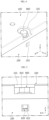
FIG. 4 is an enlarged view showing a portion A ofFIG. 1 .FIG. 5 is a side view showing the portion A ofFIG. 1 . Referring toFIGS. 4 and 5 , thedrain hole 202 of the battery pack according to an embodiment of the present disclosure may be formed in an outer surface of theside plate 200. Thedrain hole 202 may communicate with the fastening holes 103, 201 into which thefastening member 800 is inserted. - According to this configuration of the present disclosure, moisture accumulated in the
fastening member 800 may be discharged to the outside or evaporated through thedrain hole 202. -
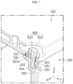
FIG. 6 is an exploded view showing a part of a partial cross-sectional configuration of the portion A ofFIG. 1 .FIG. 7 is a diagram showing a part of the partial cross-sectional configuration of the portion A ofFIG. 1 . Referring toFIGS. 6 and7 , thefastening member 800 of the battery pack according to an embodiment of the present disclosure may include ahead 810 and abody 820. Thehead 810 may be located in agroove 101. Thebody 820 may extend from thehead 810 in a lower direction or in the -Z-axis direction. Thebody 820 may have a thread formed along the longitudinal direction. - Referring to
FIGS. 6 and7 , thedrain hole 202 of the battery pack according to an embodiment of the present disclosure may expose the bottom surface 822 or the lower surface 822 of thefastening member 800. A gap or space may be formed between the lower surface 822 of thefastening member 800 and theside plate 200. - According to this configuration in the present disclosure, moisture accumulated on the lower surface 822 of the
fastening member 800 may be discharged to the outside or evaporated through thedrain hole 202. - Referring to
FIGS. 6 and7 , thedrain hole 202 of the battery pack according to an embodiment of the present disclosure may expose at least a part of theside surface 821 of thefastening member 800. - According to this configuration in the present disclosure, moisture accumulated on the
side surface 821 of thefastening member 800 may be discharged to the outside or evaporated through thedrain hole 202. - Referring to
FIGS. 6 and7 , thefastening member 800 of the battery pack according to an embodiment of the present disclosure may be located outer than thegasket 700. Thegasket 700 may be compressed and deformed by the coupling force of thefastening member 800. Thefastening member 800 may provide a coupling force so that thetop plate 100 and theside plate 200 are coupled, but it may be difficult to block moisture or foreign substances from penetrating. - According to this configuration in the present disclosure, since the
gasket 700 is located inner than thefastening member 800, it is possible to prevent or block moisture or foreign substances from penetrating into the inside of the battery pack. - Referring to
FIGS. 6 and7 , theside plate 200 of the battery pack according to an embodiment of the present disclosure may include avertical portion 204 having afastening hole 201 into which thefastening member 800 is inserted, and a firsthorizontal portion 203 extending inward from thevertical portion 204. Also, thegasket 700 may be located between the horizontal portion and thetop plate 100. - The
fastening hole 201 may be formed in the upper and lower direction or the Z-axis direction. Also, thevertical portion 204 may have a thread formed along the periphery of thefastening hole 201. Thefastening member 800 may be fastened to the thread of thevertical portion 204. Thedrain hole 202 may communicate with thefastening hole 201. Thedrain hole 202 may extend horizontally from thefastening hole 201. - The first
horizontal portion 203 may extend from the top or the upper side of thevertical portion 204 in an inward direction or the -Y-axis direction. The firsthorizontal portion 203 may support the lower surface or the inner surface of thetop plate 100. The firsthorizontal portion 203 may include a sealinggroove 102. The sealinggroove 102 may be formed on the inner surface of thetop plate 100, and thegasket 700 may be inserted or accommodated in the sealinggroove 102. Thegasket 700 may be made of a highly ductile metal material. Thegasket 700 may be positioned or fixed between thetop plate 100 and the firsthorizontal portion 203 of theside plate 200. Thegasket 700 may be compressed and deformed between thetop plate 100 and the firsthorizontal portion 203 of theside plate 200. - The first
horizontal portion 205 may form adrain hole 202. The firsthorizontal portion 205 may extend in the horizontal direction from the lower end of thevertical portion 204 or the lower end of thefastening hole 201. - According to this configuration in the present disclosure, since the
side plate 200 includes the firsthorizontal portion 203, it is possible to improve coupling with thetop plate 100 and improve the waterproof and dustproof performance of the battery pack. -
FIG. 8 is a diagram showing a modified example of the partial cross-sectional configuration of the portion A ofFIG. 1 . Referring toFIG. 8 , thedrain hole 202 of the battery pack according to an embodiment of the present disclosure may be formed to be slanted downward. - The
inclined portion 206 may form adrain hole 202. Theinclined portion 206 may extend in an oblique direction downward from the lower end of thevertical portion 204 or the lower end of thefastening hole 201. - According to this configuration of the present disclosure, moisture or foreign substances accumulated on the
drain hole 202 may be easily discharged to the outside of the battery pack along theinclined portion 206. -
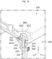
FIG. 9 is a diagram showing a modified example of the portion A ofFIG. 1 .FIG. 10 is a diagram showing a part of the partial cross-sectional configuration of the modified example of the portion A ofFIG. 9 . Referring toFIGS. 9 and10 , the battery pack according to an embodiment of the present disclosure may further include afilter 600 that covers thedrain hole 202 and has air permeability. - The
filter 600 may be attached or fastened to theside plate 200 to cover thedrain hole 202. Thefilter 600 may allow moisture accumulated indrain hole 202 to pass. Meanwhile, thefilter 600 may prevent external foreign substances from penetrating into thedrain hole 202. - According to this configuration of the present disclosure, it is possible to prevent or block foreign substances from penetrating into the
drain hole 202 while easily discharging moisture accumulated in thedrain hole 202. - A vehicle according to the present disclosure may include the battery pack according to the present disclosure described above. The battery pack according to the present disclosure may be applied to vehicles such as electric vehicles or hybrid vehicles. In addition, the vehicle according to the present disclosure may further include various other components included in the vehicle in addition to the battery pack. For example, the vehicle according to the present disclosure may further include a body, a motor, and control devices such as an ECU (electronic control unit) in addition to the battery pack according to the present disclosure.
- The terms indicating directions such as upper, lower, left, right, front and rear are used for convenience of description, but it is obvious to those skilled in the art that the terms may change depending on the position of the stated element or an observer.
- The present disclosure has been described in detail. However, it should be understood that the detailed description and specific examples, while indicating preferred embodiments of the disclosure, are given by way of illustration only, since various changes and modifications within the scope of the disclosure will become apparent to those skilled in the art from this detailed description.
Claims (10)
- A battery pack, comprising:a case configured to form an inner space and having a top plate and a side plate;a plurality of battery cells located inside the case; anda fastening member configured to penetrate the top plate and be inserted into the side plate,wherein the side plate has a drain hole that exposes the fastening member to the outside.
- The battery pack according to claim 1,
wherein the drain hole is formed in an outer surface of the side plate. - The battery pack according to claim 2,
wherein the drain hole is formed to be slanted downward. - The battery pack according to claim 1, further comprising:
a gasket fixed between the top plate and the side plate. - The battery pack according to claim 4,
wherein the fastening member is located outer than the gasket. - The battery pack according to claim 4,
wherein the side plate includes:a vertical portion having a fastening hole into which the fastening member is inserted; anda horizontal portion configured to extend inward from the vertical portion,wherein the gasket is located between the horizontal portion and the top plate. - The battery pack according to claim 1,
wherein the drain hole exposes a lower surface of the fastening member. - The battery pack according to claim 1,
wherein the drain hole exposes a side surface of the fastening member. - The battery pack according to claim 1, further comprising:
a filter configured to cover the drain hole and having air permeability. - A vehicle, comprising the battery pack according to any one of claims 1 to 9.
Applications Claiming Priority (3)
| Application Number | Priority Date | Filing Date | Title |
|---|---|---|---|
| KR20220183754 | 2022-12-23 | ||
| KR1020230105865A KR102940158B1 (en) | 2022-12-23 | 2023-08-11 | Battery pack |
| PCT/KR2023/013602 WO2024136006A1 (en) | 2022-12-23 | 2023-09-11 | Battery pack |
Publications (3)
| Publication Number | Publication Date |
|---|---|
| EP4475303A1 true EP4475303A1 (en) | 2024-12-11 |
| EP4475303A4 EP4475303A4 (en) | 2025-07-09 |
| EP4475303B1 EP4475303B1 (en) | 2026-04-29 |
Family
ID=91589175
Family Applications (1)
| Application Number | Title | Priority Date | Filing Date |
|---|---|---|---|
| EP23907293.7A Active EP4475303B1 (en) | 2022-12-23 | 2023-09-11 | Battery pack |
Country Status (4)
| Country | Link |
|---|---|
| US (1) | US20250309432A1 (en) |
| EP (1) | EP4475303B1 (en) |
| JP (1) | JP7834877B2 (en) |
| WO (1) | WO2024136006A1 (en) |
Family Cites Families (9)
| Publication number | Priority date | Publication date | Assignee | Title |
|---|---|---|---|---|
| KR100889242B1 (en) * | 2006-05-15 | 2009-03-17 | 주식회사 엘지화학 | WMS with waterproof function |
| KR20140123757A (en) * | 2013-04-15 | 2014-10-23 | 삼성에스디아이 주식회사 | Battery pack |
| KR102065096B1 (en) * | 2016-02-12 | 2020-01-10 | 주식회사 엘지화학 | Battery Pack |
| KR102133554B1 (en) * | 2016-10-21 | 2020-07-13 | 주식회사 엘지화학 | Battery pack |
| DE102018100912B4 (en) * | 2018-01-17 | 2020-12-10 | Stöcklin Logistik Ag | Battery power supply for an industrial truck and industrial truck used in a hazardous area |
| JP7484326B2 (en) * | 2020-03-30 | 2024-05-16 | マツダ株式会社 | Battery Retention Structure |
| CN113745739B (en) * | 2021-11-05 | 2022-03-25 | 北京理工大学深圳汽车研究院(电动车辆国家工程实验室深圳研究院) | Power supply system and new energy automobile |
| CN216698569U (en) * | 2021-11-24 | 2022-06-07 | 福建飞毛腿动力科技有限公司 | Battery package is around and screw hole waterproof sealing structure |
| KR102663354B1 (en) | 2022-01-05 | 2024-05-07 | 이중남 | Needle fixture of octopus fishing gear |
-
2023
- 2023-09-11 WO PCT/KR2023/013602 patent/WO2024136006A1/en not_active Ceased
- 2023-09-11 EP EP23907293.7A patent/EP4475303B1/en active Active
- 2023-09-11 US US18/863,904 patent/US20250309432A1/en active Pending
- 2023-09-11 JP JP2024544994A patent/JP7834877B2/en active Active
Also Published As
| Publication number | Publication date |
|---|---|
| JP2025503264A (en) | 2025-01-30 |
| US20250309432A1 (en) | 2025-10-02 |
| EP4475303B1 (en) | 2026-04-29 |
| EP4475303A4 (en) | 2025-07-09 |
| JP7834877B2 (en) | 2026-03-24 |
| WO2024136006A1 (en) | 2024-06-27 |
Similar Documents
| Publication | Publication Date | Title |
|---|---|---|
| US10243193B2 (en) | Battery pack | |
| EP2541650B1 (en) | Rechargeable battery having improved gasket and terminal structure | |
| US10971778B2 (en) | Battery pack | |
| EP4050715B1 (en) | Battery pack, electronic device, and vehicle | |
| KR20170095070A (en) | Battery Pack | |
| EP4475303B1 (en) | Battery pack | |
| EP4456288A1 (en) | Battery pack and energy storage system including same | |
| KR102940158B1 (en) | Battery pack | |
| KR20200055336A (en) | Battery pack | |
| CN118541861A (en) | Battery Pack | |
| KR20220021866A (en) | Battery module | |
| KR20220102303A (en) | Battery pack and device including the same | |
| EP4425670A1 (en) | Battery pack | |
| US11996571B2 (en) | Battery pack including upper frame having obliquely opened hinge fastened to side frame, and device including the same | |
| EP4576375A1 (en) | Battery pack, and energy storage system including same | |
| EP4675817A1 (en) | Battery pack | |
| KR20250163638A (en) | Battery pack and vehicle including the same | |
| KR20260059948A (en) | Current collector, Battery cell and Battery pack including the same | |
| KR20260054364A (en) | Battery cell, battery pack and vehicle including the same | |
| KR20240101319A (en) | Battery pack |
Legal Events
| Date | Code | Title | Description |
|---|---|---|---|
| STAA | Information on the status of an ep patent application or granted ep patent |
Free format text: STATUS: THE INTERNATIONAL PUBLICATION HAS BEEN MADE |
|
| PUAI | Public reference made under article 153(3) epc to a published international application that has entered the european phase |
Free format text: ORIGINAL CODE: 0009012 |
|
| STAA | Information on the status of an ep patent application or granted ep patent |
Free format text: STATUS: REQUEST FOR EXAMINATION WAS MADE |
|
| 17P | Request for examination filed |
Effective date: 20240903 |
|
| AK | Designated contracting states |
Kind code of ref document: A1 Designated state(s): AL AT BE BG CH CY CZ DE DK EE ES FI FR GB GR HR HU IE IS IT LI LT LU LV MC ME MK MT NL NO PL PT RO RS SE SI SK SM TR |
|
| A4 | Supplementary search report drawn up and despatched |
Effective date: 20250612 |
|
| RIC1 | Information provided on ipc code assigned before grant |
Ipc: H01M 50/249 20210101ALI20250605BHEP Ipc: H01M 50/691 20210101ALI20250605BHEP Ipc: H01M 50/264 20210101ALI20250605BHEP Ipc: H01M 50/24 20210101AFI20250605BHEP |
|
| GRAP | Despatch of communication of intention to grant a patent |
Free format text: ORIGINAL CODE: EPIDOSNIGR1 |
|
| STAA | Information on the status of an ep patent application or granted ep patent |
Free format text: STATUS: GRANT OF PATENT IS INTENDED |
|
| INTG | Intention to grant announced |
Effective date: 20251222 |
|
| P01 | Opt-out of the competence of the unified patent court (upc) registered |
Free format text: CASE NUMBER: UPC_APP_0000303_4475303/2026 Effective date: 20260106 |
|
| GRAS | Grant fee paid |
Free format text: ORIGINAL CODE: EPIDOSNIGR3 |
|
| GRAA | (expected) grant |
Free format text: ORIGINAL CODE: 0009210 |
|
| STAA | Information on the status of an ep patent application or granted ep patent |
Free format text: STATUS: THE PATENT HAS BEEN GRANTED |
|
| DAV | Request for validation of the european patent (deleted) | ||
| DAX | Request for extension of the european patent (deleted) | ||
| AK | Designated contracting states |
Kind code of ref document: B1 Designated state(s): AL AT BE BG CH CY CZ DE DK EE ES FI FR GB GR HR HU IE IS IT LI LT LU LV MC ME MK MT NL NO PL PT RO RS SE SI SK SM TR |
|
| REG | Reference to a national code |
Ref country code: CH Ref legal event code: F10 Free format text: ST27 STATUS EVENT CODE: U-0-0-F10-F00 (AS PROVIDED BY THE NATIONAL OFFICE) Effective date: 20260429 Ref country code: GB Ref legal event code: FG4D |
|
| REG | Reference to a national code |
Ref country code: DE Ref legal event code: R096 Ref document number: 602023016448 Country of ref document: DE |