EP4475298A1 - Battery housing assembly and lithium ion battery - Google Patents
Battery housing assembly and lithium ion battery Download PDFInfo
- Publication number
- EP4475298A1 EP4475298A1 EP23736222.3A EP23736222A EP4475298A1 EP 4475298 A1 EP4475298 A1 EP 4475298A1 EP 23736222 A EP23736222 A EP 23736222A EP 4475298 A1 EP4475298 A1 EP 4475298A1
- Authority
- EP
- European Patent Office
- Prior art keywords
- pole
- welding
- welding portion
- shell
- shell assembly
- Prior art date
- Legal status (The legal status is an assumption and is not a legal conclusion. Google has not performed a legal analysis and makes no representation as to the accuracy of the status listed.)
- Pending
Links
Images

Classifications
-
- H—ELECTRICITY
- H01—ELECTRIC ELEMENTS
- H01M—PROCESSES OR MEANS, e.g. BATTERIES, FOR THE DIRECT CONVERSION OF CHEMICAL ENERGY INTO ELECTRICAL ENERGY
- H01M50/00—Constructional details or processes of manufacture of the non-active parts of electrochemical cells other than fuel cells, e.g. hybrid cells
- H01M50/10—Primary casings; Jackets or wrappings
- H01M50/172—Arrangements of electric connectors penetrating the casing
- H01M50/174—Arrangements of electric connectors penetrating the casing adapted for the shape of the cells
- H01M50/179—Arrangements of electric connectors penetrating the casing adapted for the shape of the cells for cells having curved cross-section, e.g. round or elliptic
-
- H—ELECTRICITY
- H01—ELECTRIC ELEMENTS
- H01M—PROCESSES OR MEANS, e.g. BATTERIES, FOR THE DIRECT CONVERSION OF CHEMICAL ENERGY INTO ELECTRICAL ENERGY
- H01M50/00—Constructional details or processes of manufacture of the non-active parts of electrochemical cells other than fuel cells, e.g. hybrid cells
- H01M50/10—Primary casings; Jackets or wrappings
- H01M50/102—Primary casings; Jackets or wrappings characterised by their shape or physical structure
- H01M50/107—Primary casings; Jackets or wrappings characterised by their shape or physical structure having curved cross-section, e.g. round or elliptic
-
- H—ELECTRICITY
- H01—ELECTRIC ELEMENTS
- H01M—PROCESSES OR MEANS, e.g. BATTERIES, FOR THE DIRECT CONVERSION OF CHEMICAL ENERGY INTO ELECTRICAL ENERGY
- H01M10/00—Secondary cells; Manufacture thereof
- H01M10/05—Accumulators with non-aqueous electrolyte
- H01M10/052—Li-accumulators
- H01M10/0525—Rocking-chair batteries, i.e. batteries with lithium insertion or intercalation in both electrodes; Lithium-ion batteries
-
- H—ELECTRICITY
- H01—ELECTRIC ELEMENTS
- H01M—PROCESSES OR MEANS, e.g. BATTERIES, FOR THE DIRECT CONVERSION OF CHEMICAL ENERGY INTO ELECTRICAL ENERGY
- H01M50/00—Constructional details or processes of manufacture of the non-active parts of electrochemical cells other than fuel cells, e.g. hybrid cells
- H01M50/10—Primary casings; Jackets or wrappings
- H01M50/147—Lids or covers
- H01M50/148—Lids or covers characterised by their shape
- H01M50/152—Lids or covers characterised by their shape for cells having curved cross-section, e.g. round or elliptic
-
- H—ELECTRICITY
- H01—ELECTRIC ELEMENTS
- H01M—PROCESSES OR MEANS, e.g. BATTERIES, FOR THE DIRECT CONVERSION OF CHEMICAL ENERGY INTO ELECTRICAL ENERGY
- H01M50/00—Constructional details or processes of manufacture of the non-active parts of electrochemical cells other than fuel cells, e.g. hybrid cells
- H01M50/10—Primary casings; Jackets or wrappings
- H01M50/147—Lids or covers
- H01M50/166—Lids or covers characterised by the methods of assembling casings with lids
- H01M50/169—Lids or covers characterised by the methods of assembling casings with lids by welding, brazing or soldering
-
- H—ELECTRICITY
- H01—ELECTRIC ELEMENTS
- H01M—PROCESSES OR MEANS, e.g. BATTERIES, FOR THE DIRECT CONVERSION OF CHEMICAL ENERGY INTO ELECTRICAL ENERGY
- H01M50/00—Constructional details or processes of manufacture of the non-active parts of electrochemical cells other than fuel cells, e.g. hybrid cells
- H01M50/50—Current conducting connections for cells or batteries
- H01M50/528—Fixed electrical connections, i.e. not intended for disconnection
-
- H—ELECTRICITY
- H01—ELECTRIC ELEMENTS
- H01M—PROCESSES OR MEANS, e.g. BATTERIES, FOR THE DIRECT CONVERSION OF CHEMICAL ENERGY INTO ELECTRICAL ENERGY
- H01M50/00—Constructional details or processes of manufacture of the non-active parts of electrochemical cells other than fuel cells, e.g. hybrid cells
- H01M50/50—Current conducting connections for cells or batteries
- H01M50/543—Terminals
- H01M50/545—Terminals formed by the casing of the cells
-
- H—ELECTRICITY
- H01—ELECTRIC ELEMENTS
- H01M—PROCESSES OR MEANS, e.g. BATTERIES, FOR THE DIRECT CONVERSION OF CHEMICAL ENERGY INTO ELECTRICAL ENERGY
- H01M50/00—Constructional details or processes of manufacture of the non-active parts of electrochemical cells other than fuel cells, e.g. hybrid cells
- H01M50/50—Current conducting connections for cells or batteries
- H01M50/543—Terminals
- H01M50/552—Terminals characterised by their shape
- H01M50/559—Terminals adapted for cells having curved cross-section, e.g. round, elliptic or button cells
-
- H—ELECTRICITY
- H01—ELECTRIC ELEMENTS
- H01M—PROCESSES OR MEANS, e.g. BATTERIES, FOR THE DIRECT CONVERSION OF CHEMICAL ENERGY INTO ELECTRICAL ENERGY
- H01M50/00—Constructional details or processes of manufacture of the non-active parts of electrochemical cells other than fuel cells, e.g. hybrid cells
- H01M50/50—Current conducting connections for cells or batteries
- H01M50/543—Terminals
- H01M50/564—Terminals characterised by their manufacturing process
- H01M50/566—Terminals characterised by their manufacturing process by welding, soldering or brazing
-
- H—ELECTRICITY
- H01—ELECTRIC ELEMENTS
- H01M—PROCESSES OR MEANS, e.g. BATTERIES, FOR THE DIRECT CONVERSION OF CHEMICAL ENERGY INTO ELECTRICAL ENERGY
- H01M50/00—Constructional details or processes of manufacture of the non-active parts of electrochemical cells other than fuel cells, e.g. hybrid cells
- H01M50/50—Current conducting connections for cells or batteries
- H01M50/572—Means for preventing undesired use or discharge
- H01M50/584—Means for preventing undesired use or discharge for preventing incorrect connections inside or outside the batteries
- H01M50/59—Means for preventing undesired use or discharge for preventing incorrect connections inside or outside the batteries characterised by the protection means
- H01M50/593—Spacers; Insulating plates
-
- Y—GENERAL TAGGING OF NEW TECHNOLOGICAL DEVELOPMENTS; GENERAL TAGGING OF CROSS-SECTIONAL TECHNOLOGIES SPANNING OVER SEVERAL SECTIONS OF THE IPC; TECHNICAL SUBJECTS COVERED BY FORMER USPC CROSS-REFERENCE ART COLLECTIONS [XRACs] AND DIGESTS
- Y02—TECHNOLOGIES OR APPLICATIONS FOR MITIGATION OR ADAPTATION AGAINST CLIMATE CHANGE
- Y02E—REDUCTION OF GREENHOUSE GAS [GHG] EMISSIONS, RELATED TO ENERGY GENERATION, TRANSMISSION OR DISTRIBUTION
- Y02E60/00—Enabling technologies; Technologies with a potential or indirect contribution to GHG emissions mitigation
- Y02E60/10—Energy storage using batteries
Definitions
- the present disclosure relates to the field of batteries, and in particular, to a battery shell assembly and a lithium-ion battery.
- cylindrical lithium-ion battery has advantages such as high energy density and power density, high operating voltage, light weight, small size, long cycle life, good safety, environmental protection, and the like. It has a wide application prospect in portable appliances, electric tools, large-scale energy storage, electric traffic power supply, and the like. Lithium-ion batteries are usually assembled by welding to realize the conduction of internal core circuits.
- the present disclosure provide a battery shell assembly and a lithium-ion battery, which can solve a problem of poor welding quality between the battery shell assembly and an external circuit.
- an embodiment of the present disclosure provides a battery shell assembly including:
- an embodiment of the present disclosure provides a lithium-ion battery including:
- a battery shell assembly includes a shell, a pole and a connection terminal.
- the shell is formed with an accommodating cavity, and the an accommodating cavity is configured to place a core.
- the shell has a first end and a second end that are opposite to each other, and the first end is provided with an opening communicating with the accommodating cavity.
- the pole is located at the first end of the shell, and the pole is insulatively connected to the shell.
- One side of the pole facing the accommodating cavity is disposed to be electrically connected with the core.
- the connection terminal is disposed on one side of the pole away from the shell.
- the connection terminal has a first welding portion and a second welding portion connected to each other, wherein the second welding portion is protrudingly disposed on one side of the first welding portion away from the pole, the first welding portion is electrically connected with the pole, and the second welding portion is configured to be electrically connected with an external circuit.
- the first welding portion and the second welding portion are provided at the connection terminal, the first welding portion is electrically connected with the pole, the second welding portion is electrically connected with an external circuit, so as to realize the conduction between a battery and an external circuit. Meanwhile, the second welding portion protrudes from the first welding portion, so that the welding between the second welding portion and the external circuit will not be affected after the first welding portion and the pole are welded, thereby improving the welding reliability and welding efficiency of the connecting terminal and the external circuit.
- connection In the description of the present disclosure, unless otherwise expressly specified and limited, the terms “connected”, “connecting” are to be construed in a broad sense, for example, as fixed connected, detachably connected, mechanically connected, electrically connection, directly connected or indirectly connected via an intermediary; or internally connection of two components or interaction relationship between two components.
- connection For those of ordinary skill in the art, specific meanings of the preceding terms in the present disclosure may be construed based on specific situations.
- first feature and the second feature may be in direct contact, or be in contact via another feature between the two features.
- first feature is described as “on”, “above” or “over” the second feature, the first feature is right on, above or over the second feature or the first feature is obliquely on, above or over the second feature, or the first feature is simply at a higher level than the second feature.
- the first feature When the first feature is described as “under”, “below” or “underneath” the second feature, the first feature is right under, below or underneath the second feature or the first feature is obliquely under, below or underneath the second feature, or the first feature is simply at a lower level than the second feature.
- Embodiments of the present disclosure provide a battery shell assembly and a lithium-ion battery, which are described in detail below. It should be noted that the order in which the following embodiments are described is not intended to limit the preferred order of the embodiments.
- the battery shell assembly 100 includes a shell 110, which is formed with an accommodating cavity 111 configured to place a core 200.
- the shell 110 has a first end 112 and a second end 113 that are opposite to each other, wherein the first end 112 is provided with an opening 114 communicating with the accommodating cavity 111.
- the shell 110 includes a shell main body and a cover plate, and an opening 114 is provided on the cover plate, wherein the cover plate and the shell main body are welded to form the shell 110 containing the core 200 and the electrolyte.
- the battery shell assembly 100 includes a pole 120 located at a first end 112 of the shell 110, the pole 120 is insulatively connected to the shell 110, and one side of the pole 120 facing the accommodating cavity 111 is disposed to be electrically with the core 200. That is, the pole 120 serves as an output terminal of the core 200 for conducting the core 200 with an external circuit. Since the pole 120 is insulatively connected to the shell 110, if one electrode of the core 200 is electrically connected to the pole 120 and the other electrode is directly electrically connected to the shell 110, so that positive electrode and negative electrode of the core 200 are located on the same side of the battery shell assembly 100.
- the battery shell assembly 100 includes a connection terminal 130 disposed on one side of the pole 120 away from the shell 110.
- the connection terminal 130 has a first welding portion 131 and a second welding portion 133 connected to each other, wherein the second welding portion 133 is protrudingly disposed on one side of the first welding portion 131 away from the pole 120, the first welding portion 131 is electrically connected with the pole 120, and the second welding portion 133 is configured to be electrically connected with an external circuit. Since the pole 120 is electrically connected with the core 200, the connection between the core 200 and an external circuit can be realized by electrically connecting the first welding portion 131 with the pole 120, and electrically connecting the second welding portion 133 with an external circuit.
- the second welding portion protrudes from the first welding portion, so that a stepped structure is formed between the second welding portion 133 and the first welding portion 131, thus the welding between the second welding portion 133 and the external circuit will not be affected after the first welding portion 131 and the pole are welded, thereby improving the welding reliability and welding efficiency of the connecting terminal 130 and the external circuit.
- the battery shell assembly 100 provided in embodiments of the present disclosure includes a shell 110, a pole 120 and a connection terminal 130.
- the shell 110 is formed with an accommodating cavity 111 which is configured to place a core 200.
- the shell 110 has a first end 112 and a second end 113 that are opposite to each other, wherein the first end 112 is provided with an opening 114 communicating with the accommodating cavity 111.
- the pole 120 is located at the first end 112 of the shell 110.
- the pole 120 is insulatively connected to the shell 110, and one side of the pole 120 facing the accommodating cavity 111 is disposed to be electrically connected with the core 200.
- the connection terminal 130 is located on the side of the pole 120 away from the shell 110.
- the connection terminal 130 has a first welding portion 131 and a second welding portion 133 connected to each other, wherein the second welding portion 133 is protrudingly disposed on one side of the first welding portion 131 away from the pole 120, the first welding portion 131 is electrically connected with the pole 120, and the second welding portion 133 is disposed to be electrically connected with an external circuit.
- the first welding portion 131 and the second welding portion 133 are provided at the connection terminal 130, the first welding portion 131 is electrically connected with the pole 120, the second welding portion 133 is electrically connected with an external circuit, so as to realize the conduction between a battery and an external circuit.
- the second welding portion 133 protrudes from the first welding portion 131, so that the welding between the second welding portion 133 and the external circuit will not be affected after the first welding portion 131 and the pole 120 are welded, thereby improving the welding reliability and welding efficiency of the connecting terminal and the external circuit.
- one side of the first welding portion 131 facing the pole 120 has a first welding area 132 configured to be electrically connected with the pole 120, and the first welding area 132 is disposed around an edge of the second welding portion 133. That is, the second welding portion 133 is located in an area close to the middle of the first welding portion 131. It also means that the entire edge area of the connection terminal 130 is used for electrical connection with the pole 120, and the middle area is used for electrical connection with an external circuit, such as a bar.
- This structure is designed so that the welding of the connection terminal 130 to the inner structure (pole 120) and the welding of an external structure (a bar) do not interfere with each other, and the positioning of the connection terminal 130 to the structure such as the bar is facilitated, thereby improving the welding stability and welding efficiency.
- An orthographic projection of the second welding portion 133 on the shell 110 covers the opening 14.
- the opening 114 can be designed in the middle of the first end 112 of the shell 110 to facilitate the electrical connection with the core 200 in the accommodating cavity 111.
- the orthographic projection of the second welding portion 133 on the shell 110 is set to cover the opening 114, so that the second welding portion 133 can also be located in the middle of the whole battery shell assembly 100, which is helpful for the positioning of an external structure such as a bar with the connection terminal 130, thus improving the welding efficiency.
- a difference in height between the side of the first welding portion 131 away from the pole 120 and one side of the second welding portion 133 away from the pole 120 is greater than or equal to 0.4 mm and less than or equal to 0.8 mm. That is, the thickness of the second welding portion 133 is greater than or equal to 0.4 mm and less than or equal to 0.8 mm.
- the second welding portion 133 protrudes from the first welding portion 131, and the welding area of the first welding portion 131 is disposed around the edge of the second welding portion 133, if the thickness of the second welding portion 133 is too small, the welding pattern formed after the first welding portion 131 is connected with the pole 120 in the first welding area 132 may protrude from the side of the second welding portion 133 away from the pole 120, thus affecting the effective welding between an external structure such as a bar and the second welding portion 133. If the thickness of the second welding portion 133 is too large, it will cause the overall height of the battery shell assembly 100 to be too large, causing the volume proportion of the battery shell assembly 100 to be too large, which is not conducive to the high energy density design of the lithium-ion battery 10.
- the difference in height between the side of the first welding portion 131 away from the pole 120 and one side of the second welding portion 133 away from the pole 120 can be set to 0.4 mm, 0.5 mm, 0.6 mm, 0.7mm, 0.8 mm, or the like, and the specific value can be adjusted according to actual use requirements, it is only necessary to ensure the effective welding between the second welding portion 133 and an external structure such as a bar and reduce the volume proportion of the whole battery shell assembly 100, which is not particularly limited herein.
- the thickness of the first welding portion 131 is greater than or equal to 0.3 mm and less than or equal to 0.6 mm.
- the first welding portion 131 is mainly welded to the pole 120 through the first welding area 132. If the thickness of the first welding portion 131 is too small, the internal resistance of the first welding portion 131 will be too large. If the thickness of the first welding portion 131 is too large, the thickness of laser penetration during welding will increase, and the required laser energy will also increase, which will increase the manufacturing cost and meanwhile affect the welding quality.
- the thickness of the first welding portion 131 can be set to 0.3 mm, 0.4 mm, 0.5 mm, or 0.6 mm.
- the specific value of the first welding portion 131 can be adjusted according to actual use requirements, it is only necessary to ensure the welding quality between the first welding portion 131 and the pole 120 while the internal resistance of the first welding part 131 is appropriate, which is not particularly limited herein.
- first welding portion 131 and the second welding portion 133 in embodiments of the present disclosure are integrally formed. That is, the first welding portion 131 and the second welding portion 133 are are a whole, and the whole is in a stepped structure.
- This stepped structure enables the connection terminal 130 to be welded to the pole 120 through the first welding area 132 of the outer ring, and welded to an external structure such as a bar through the second welding portion 133 in the middle, which can realize the connection between the core 200 and an external structure while avoiding interference between each other during welding, thereby improving the stability of welding.
- this stepped structure is also helpful for rapid positioning of an external structure such as a bar with the connection terminal 130 during welding, thereby improving the welding efficiency.
- the side of the pole 120 facing the accommodating cavity 111 has a second welding area 121 disposed to be electrically connected with the core 200.
- the second welding area 121 is disposed corresponding to the second welding portion 133.
- An orthographic projection of the second welding portion 133 on the shell 110 covers an orthographic projection of the second welding area 121 on the shell 110. Since the pole 120 is welded to the first welding area 132 of the first welding portion 131, the first welding area 132 is provided around the second welding portion 133. That is, the orthographic projection of the first welding area 132 on the shell 110 is annular.
- the orthographic projection of the second welding portion 133 on the shell 110 is set to cover the orthographic projection of the second welding area 121 on the shell 110, so that the second welding area 121 is located in an area where the second welding portion 133 is located. That is, the orthographic projection of the second welding area 121 on the shell 110 is located in the orthographic projection of the first welding area 132 on the shell 110, so that the welding area between the pole 120 and the connection terminal 130 and the welding area between the pole 120 and the core 200 are independent from each other, so as to avoid mutual interference during welding, and further improve the welding stability of the pole 120.
- one side of the pole 120 away from the accommodating cavity 111 is provided with a positioning groove 122 that corresponds to the second welding area 121.
- the side of the first welding portion 131 facing the pole 120 is protrudingly provided with a positioning portion 134 that corresponds to the positioning groove 122.
- the positioning portion 134 is inserted into the positioning groove 122. That is, when the connection terminal 130 is welded to the pole 120, the positioning portion 134 of the connection terminal 130 is inserted into the positioning groove 122 in the pole 120 firstly to define the relative position of the connection terminal 130 and the pole 120, so as to realize positioning of the connection terminal 130. Then the first welding area 132 of the connection terminal 130 is laser welded to realize the electrical connection between the connection terminal 130 and the pole 120.
- a side wall of the positioning groove 122 is at least partially expanding in a direction away from the accommodating cavity 111.
- the side wall of the positioning groove 122 is in the shape of an overall expanded funnel-shaped structure in the direction away from the accommodating cavity 111. That is, the cross section of the positioning groove 122 has an inverted trapezoidal structure.
- the positioning portion 134 has a conical structure with an inverted trapezoidal cross section. This structural design enables the positioning portion 134 to slide into the positioning groove 122 along the side wall of the positioning groove 122 even if there is a deviation when inserting the positioning portion 134 into the positioning groove 122, thereby reducing the positioning accuracy between the connection terminal 130 and the pole 120.
- an obtuse angle is formed between the side wall of the positioning groove 122 and a bottom of the positioning groove 122, and an included angle formed between the side wall of the positioning groove 122 and the bottom of the positioning groove 122 is smaller than an included angle formed between a side wall of the positioning portion 134 and the bottom of the positioning groove 122. That is, after the positioning portion 134 of the connection terminal 130 is inserted into the positioning groove 122 of the pole 120, there is a gap present between the side wall of the positioning portion 134 and the side wall of the positioning groove 122, so as to facilitate smooth assembly of the connection terminal 130 and the pole 120.
- a gap can be present between the positioning portion 134 and the bottom of the positioning groove 122. That is, the positioning portion 134 abuts against the side wall of the positioning groove 122 through the side surface.
- the connection terminal 130 and the pole 120 By setting a gap between the positioning portion 134 and the bottom of the positioning groove 122, it is possible to prevent the connection terminal 130 and the pole 120 from being stuck during assembly, or to avoid the situation that when the positioning portion 134 of the connection terminal 130 abuts against the bottom of the positioning groove 122 of the pole 120, the first welding portion 131 of the connection terminal 130 is not in contact with the surface of the pole 120, thereby affecting the effective welding between the connection terminal 130 and the pole 120.
- the positioning portion 134 and the bottom of the positioning groove 122 it is possible to reduce the overall weight of the battery shell assembly 100 while ensuring the effective positioning between the connection terminal 130 and the pole 120, thereby improving the energy density of the lithium-ion battery 10.
- the thickness of the bottom of the positioning groove 122 is greater than or equal to 0.8 mm and less than or equal to 1.5 mm. That is, the thickness of the pole 120 corresponding to the position of the second welding area 121 is greater than or equal to 0.8 mm and less than or equal to 1.5 mm. If the thickness is too small, the internal resistance of the pole 120 will be too large. If the thickness is too large, the thickness of laser penetration during welding will increase, and the required laser energy will also increase, which will increase the manufacturing cost and meanwhile affect the welding quality.
- the thickness of the bottom of the positioning groove 122 can be set to 0.8 mm, 1.0 mm, 1.2 mm, 1.5 mm, or the like.
- the specific value can be adjusted according to actual use requirements, it is only necessary to ensure the welding quality between the pole 120 and the core 200 while the internal resistance of the pole 120 is appropriate, which is not particularly limited herein.
- the diameter of the positioning groove 122 is greater than or equal to 2 mm and less than or equal to 5 mm.
- the diameter of the positioning groove 122 directly reflects the size of the weldable area between the pole 120 and the core200. If the diameter of the positioning groove 122 is too small, the effective welding area between the pole 120 and the core 200 will be too small, thus affecting the welding stability between the pole 120 and the core 200. If the diameter of the positioning groove 122 is too large, the opening 114 in the shell 110 will be too large, which is not conducive to sealing of the battery shell assembly 100.
- the diameter of the positioning groove 122 can be set to 2 mm, 3 mm, 4 mm, 5 mm, or the like.
- the specific value can be adjusted according to actual use requirements, it is only necessary to ensure the welding stability between the pole 120 and the core 200 while avoiding impacts on the sealing of the battery shell assembly 100, which is not particularly limited herein.
- the pole 120 includes a first connecting portion 123 extending into the accommodating cavity 111, and a second connecting portion 124 extending out of the opening 114.
- the first connecting portion 123 is configured to be electrically connected with the core 200.
- the second connecting portion 124 is configured to be electrically connected to the first welding portion 123.
- the battery shell assembly 100 further includes a first insulating member 140 and a second insulating member 150.
- the first insulating member 140 is disposed between the first connecting portion 123 and an inner surface of the shell 110
- the second insulating member 150 is disposed between the second connecting portion 124 and an outer surface of the shell 110 to insulatively connect the pole 120 to the shell 110.
- the pole 120 when the pole 120 is riveted with the shell 110, the pole 120 is extended into the first connecting portion 123 of the accommodating cavity 111 through the first insulating member 140, so as to be separated from the shell 110, thus the pole 120 is insulated from the inner surface of the shell 110, and the pole 120 and the inner surface of the shell 110 are sealed as well.
- the second connecting portion 124 of the pole 120 extending out of the opening 114 is separated from the shell 110 through the second insulating member 150, so that the pole 120 is insulated from the outer surface of the shell 110, and the pole 120 and the outer surface of the shell 110 are sealed as well.
- a pressing block 160 is disposed between the first insulating member 140 and the first connecting portion 123.
- the pressing block 160 has a hardness greater than that of the pole 120.
- the sealing of the first insulating member 140 to the pole 120 and the inner surface of the shell 110 can be strengthened by riveting the first insulating member 140, the pressing block 160, and the first connecting portion 123 to each other.
- embodiments of the present disclosure further provide a lithium-ion battery including a battery shell assembly, and a specific structure of the battery shell assembly is described with reference to the foregoing embodiments. Since the lithium-ion battery adopts all the technical solutions of all the foregoing embodiments, it has at least all the beneficial effects brought by the technical solutions of the foregoing embodiments, which will not be repeated herein.
- the lithium-ion battery 10 includes a battery shell assembly 100 and a core 200 disposed within an accommodating cavity 111 of the battery shell assembly 100.
- the core 200 has a first electrode and a second electrode.
- the first electrode is electrically connected to the pole 120 of the battery shell assembly 100
- the second electrode electrically connected to the shell 110 of the battery shell assembly 100. That is, the pole 120 and the entire shell 110 are respectively used as two output terminals of the lithium-ion battery 10, so that the positive electrode and negative electrode of the lithium-ion battery 10 are located on the same side of the battery shell assembly 100, which is convenient for the assembly of subsequent modules.
- the first electrode can be a positive electrode of the core 200
- the second electrode can be a negative electrode of the core 200, so the pole 120 and the connection terminal 130 in the battery shell assembly 100 together form the positive output terminal of the lithium-ion battery 10.
- the shell 110 is the negative output terminal of the lithium-ion battery 10.
- the battery shell assembly 100 in embodiments of the present disclosure includes a shell 110, a pole 120 and a connection terminal 130.
- the shell 110 is formed with an accommodating cavity 111 configured to place a core 200.
- the shell 110 has a first end 112 and a second end 113 that are opposite to each other.
- the first end 112 is provided with an opening 114 communicating with the accommodating cavity 111.
- the pole 120 is disposed at the first end 112 of the shell 110.
- the pole 120 is insulatively connected to the shell 110, and one side of the pole 120 facing the accommodating cavity 111 is disposed to be electrically connected with the core 200.
- the connection terminal 130 is located on the side of the pole 120 away from the shell 110.
- the connection terminal 130 has a first welding portion 131 and a second welding portion 133 connected to each other, wherein the second welding portion 133 is protrudingly disposed on one side of the first welding portion 131 away from the pole 120, the first welding portion 131 is electrically connected with the pole 120, and the second welding portion 133 is disposed to be electrically connected with an external circuit.
- the first welding portion 131 and the second welding portion 133 are provided at the connection terminal 130, the first welding portion 131 is electrically connected with the pole 120, the second welding portion 133 is electrically connected with an external circuit, so as to realize the conduction between a battery and an external circuit.
- the second welding portion 133 protrudes from the first welding portion 131, so that the welding between the second welding portion 133 and the external circuit will not be affected after the first welding portion 131 and the pole 120 are welded, thereby improving the welding reliability and welding efficiency of the connecting terminal and the external circuit.
Landscapes
- Chemical & Material Sciences (AREA)
- Chemical Kinetics & Catalysis (AREA)
- Electrochemistry (AREA)
- General Chemical & Material Sciences (AREA)
- Engineering & Computer Science (AREA)
- Manufacturing & Machinery (AREA)
- Materials Engineering (AREA)
- Connection Of Batteries Or Terminals (AREA)
- Secondary Cells (AREA)
- Sealing Battery Cases Or Jackets (AREA)
Abstract
Description
- The present disclosure claims priority to
Chinese Patent Application No. 202320948952.0, filed on April 24, 2023 - The present disclosure relates to the field of batteries, and in particular, to a battery shell assembly and a lithium-ion battery.
- With the rapid growth of population and the rapid development of social economy, resources and energy are becoming increasingly scarce, and environmental protection has been paid more and more attention. The development and conservation of energy has become an important topic in the world today. Energy is the foundation of the existence and development of human society, and today's society based on mineral energy encounters energy shortage and environmental pollution crisis more and more frequently.
- Meanwhile, with the advent of the information high-tech era, the application form of energy is changing, and the demand for mobile high-performance power supply, which is renewable, pollution-free, small and discrete, is growing rapidly. As a novel secondary battery, cylindrical lithium-ion battery has advantages such as high energy density and power density, high operating voltage, light weight, small size, long cycle life, good safety, environmental protection, and the like. It has a wide application prospect in portable appliances, electric tools, large-scale energy storage, electric traffic power supply, and the like. Lithium-ion batteries are usually assembled by welding to realize the conduction of internal core circuits.
- However, the battery shell assembly in the related arts cannot provide effective welding areas to connect with external circuit structures, such as bars, after completing the connection with the internal core, resulting in poor welding quality between the battery shell assembly and the external circuits, which is not conducive to the assembly and use of lithium-ion batteries.
- The present disclosure provide a battery shell assembly and a lithium-ion battery, which can solve a problem of poor welding quality between the battery shell assembly and an external circuit.
- For this purpose, the present disclosure adopts the following technical solutions:
- In a first aspect, an embodiment of the present disclosure provides a battery shell assembly including:
- a shell formed with an accommodating cavity, the accommodating cavity being configured to place a core; the shell having a first end and a second end that are opposite to each other, and the first end being provided with an opening communicating with the accommodating cavity;
- a pole located at the first end of the shell, the pole being insulatively connected to the shell, and one side of the pole facing the accommodating cavity being disposed to be electrically connected with the core; and
- a connection terminal disposed on one side of the pole away from the shell, the connection terminal having a first welding portion and a second welding portion connected to each other, the second welding portion being protrudingly disposed on one side of the first welding portion away from the pole; the first welding portion being electrically connected with the pole, and the second welding portion being configured to be electrically connected with an external circuit.
- In a second aspect, an embodiment of the present disclosure provides a lithium-ion battery including:
- the battery shell assembly according to the above;
- a core located within an accommodating cavity of the battery shell assembly, wherein the core has a first electrode electrically connected to a pole of the battery shell assembly, and a second electrode electrically connected to a shell of the battery shell assembly.
- In embodiments of the present disclosure, a battery shell assembly includes a shell, a pole and a connection terminal. The shell is formed with an accommodating cavity, and the an accommodating cavity is configured to place a core. The shell has a first end and a second end that are opposite to each other, and the first end is provided with an opening communicating with the accommodating cavity. The pole is located at the first end of the shell, and the pole is insulatively connected to the shell. One side of the pole facing the accommodating cavity is disposed to be electrically connected with the core. The connection terminal is disposed on one side of the pole away from the shell. The connection terminal has a first welding portion and a second welding portion connected to each other, wherein the second welding portion is protrudingly disposed on one side of the first welding portion away from the pole, the first welding portion is electrically connected with the pole, and the second welding portion is configured to be electrically connected with an external circuit. In the present disclosure, the first welding portion and the second welding portion are provided at the connection terminal, the first welding portion is electrically connected with the pole, the second welding portion is electrically connected with an external circuit, so as to realize the conduction between a battery and an external circuit. Meanwhile, the second welding portion protrudes from the first welding portion, so that the welding between the second welding portion and the external circuit will not be affected after the first welding portion and the pole are welded, thereby improving the welding reliability and welding efficiency of the connecting terminal and the external circuit.
-
-
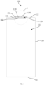
FIG. 1 is a schematic structural diagram of a battery shell assembly according to an embodiment of the present disclosure; -
FIG. 2 is an enlarged structural diagram of area A inFIG. 1 according to an embodiment of the present disclosure; and -
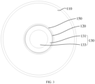
FIG. 3 is a top view of area A inFIG. 1 according to an embodiment of the present disclosure; and -
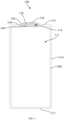
FIG. 4 is a schematic structural diagram of a lithium-ion battery according to an embodiment of the present disclosure. -
- 10, a lithium-ion battery;
- 100, battery shell assembly; 110, shell; 111, accommodating cavity; 112, first end; 113, second end; 114, opening; 120, pole; 121, second welding area; 122, positioning groove; 123, first connecting portion; 124, second connecting portion; 130, connection terminal; 131, first welding portion; 132, first welding area; 133, second welding portion; 134, positioning portion; 140, first insulating member; 150, second insulating member; 160, pressing block;
- 200, core.
- In the description of the present disclosure, unless otherwise expressly specified and limited, the terms "connected", "connecting" are to be construed in a broad sense, for example, as fixed connected, detachably connected, mechanically connected, electrically connection, directly connected or indirectly connected via an intermediary; or internally connection of two components or interaction relationship between two components. For those of ordinary skill in the art, specific meanings of the preceding terms in the present disclosure may be construed based on specific situations.
- In the present disclosure, unless otherwise expressly specified and limited, when a first feature is described as "above" or "below" a second feature, the first feature and the second feature may be in direct contact, or be in contact via another feature between the two features. Moreover, when the first feature is described as "on", "above" or "over" the second feature, the first feature is right on, above or over the second feature or the first feature is obliquely on, above or over the second feature, or the first feature is simply at a higher level than the second feature. When the first feature is described as "under", "below" or "underneath" the second feature, the first feature is right under, below or underneath the second feature or the first feature is obliquely under, below or underneath the second feature, or the first feature is simply at a lower level than the second feature.
- Embodiments of the present disclosure provide a battery shell assembly and a lithium-ion battery, which are described in detail below. It should be noted that the order in which the following embodiments are described is not intended to limit the preferred order of the embodiments.
- Firstly, an embodiment of the present disclosure provides a battery shell assembly and a lithium-ion battery. As shown in
FIG. 1 , thebattery shell assembly 100 includes ashell 110, which is formed with anaccommodating cavity 111 configured to place acore 200. Theshell 110 has afirst end 112 and asecond end 113 that are opposite to each other, wherein thefirst end 112 is provided with an opening 114 communicating with theaccommodating cavity 111. Theshell 110 includes a shell main body and a cover plate, and anopening 114 is provided on the cover plate, wherein the cover plate and the shell main body are welded to form theshell 110 containing thecore 200 and the electrolyte. - The
battery shell assembly 100 includes apole 120 located at afirst end 112 of theshell 110, thepole 120 is insulatively connected to theshell 110, and one side of thepole 120 facing theaccommodating cavity 111 is disposed to be electrically with thecore 200. That is, thepole 120 serves as an output terminal of thecore 200 for conducting thecore 200 with an external circuit. Since thepole 120 is insulatively connected to theshell 110, if one electrode of thecore 200 is electrically connected to thepole 120 and the other electrode is directly electrically connected to theshell 110, so that positive electrode and negative electrode of thecore 200 are located on the same side of thebattery shell assembly 100. - As shown in
FIGs. 2 and3 , thebattery shell assembly 100 includes aconnection terminal 130 disposed on one side of thepole 120 away from theshell 110. Theconnection terminal 130 has afirst welding portion 131 and asecond welding portion 133 connected to each other, wherein thesecond welding portion 133 is protrudingly disposed on one side of thefirst welding portion 131 away from thepole 120, thefirst welding portion 131 is electrically connected with thepole 120, and thesecond welding portion 133 is configured to be electrically connected with an external circuit. Since thepole 120 is electrically connected with thecore 200, the connection between thecore 200 and an external circuit can be realized by electrically connecting thefirst welding portion 131 with thepole 120, and electrically connecting thesecond welding portion 133 with an external circuit. Meanwhile, the second welding portion protrudes from the first welding portion, so that a stepped structure is formed between thesecond welding portion 133 and thefirst welding portion 131, thus the welding between thesecond welding portion 133 and the external circuit will not be affected after thefirst welding portion 131 and the pole are welded, thereby improving the welding reliability and welding efficiency of the connectingterminal 130 and the external circuit. - The
battery shell assembly 100 provided in embodiments of the present disclosure includes ashell 110, apole 120 and aconnection terminal 130. Theshell 110 is formed with anaccommodating cavity 111 which is configured to place acore 200. Theshell 110 has afirst end 112 and asecond end 113 that are opposite to each other, wherein thefirst end 112 is provided with an opening 114 communicating with theaccommodating cavity 111. Thepole 120 is located at thefirst end 112 of theshell 110. Thepole 120 is insulatively connected to theshell 110, and one side of thepole 120 facing theaccommodating cavity 111 is disposed to be electrically connected with thecore 200. Theconnection terminal 130 is located on the side of thepole 120 away from theshell 110. Theconnection terminal 130 has afirst welding portion 131 and asecond welding portion 133 connected to each other, wherein thesecond welding portion 133 is protrudingly disposed on one side of thefirst welding portion 131 away from thepole 120, thefirst welding portion 131 is electrically connected with thepole 120, and thesecond welding portion 133 is disposed to be electrically connected with an external circuit. In the present disclosure, thefirst welding portion 131 and thesecond welding portion 133 are provided at theconnection terminal 130, thefirst welding portion 131 is electrically connected with thepole 120, thesecond welding portion 133 is electrically connected with an external circuit, so as to realize the conduction between a battery and an external circuit. Meanwhile, thesecond welding portion 133 protrudes from thefirst welding portion 131, so that the welding between thesecond welding portion 133 and the external circuit will not be affected after thefirst welding portion 131 and thepole 120 are welded, thereby improving the welding reliability and welding efficiency of the connecting terminal and the external circuit. - Optionally, one side of the
first welding portion 131 facing thepole 120 has afirst welding area 132 configured to be electrically connected with thepole 120, and thefirst welding area 132 is disposed around an edge of thesecond welding portion 133. That is, thesecond welding portion 133 is located in an area close to the middle of thefirst welding portion 131. It also means that the entire edge area of theconnection terminal 130 is used for electrical connection with thepole 120, and the middle area is used for electrical connection with an external circuit, such as a bar. This kind of structural design makes the welding between theconnection terminal 130 and the internal structure (pole 120) and the welding between theconnection terminal 130 and the external structure (bar) do not interfere with each other, it also helps the positioning of theconnection terminal 130 and other structures such as a bar during welding, thus improving the welding stability and efficiency. This structure is designed so that the welding of theconnection terminal 130 to the inner structure (pole 120) and the welding of an external structure (a bar) do not interfere with each other, and the positioning of theconnection terminal 130 to the structure such as the bar is facilitated, thereby improving the welding stability and welding efficiency. - An orthographic projection of the
second welding portion 133 on theshell 110 covers the opening 14. When designing the overall structure of thebattery shell assembly 100, theopening 114 can be designed in the middle of thefirst end 112 of theshell 110 to facilitate the electrical connection with the core 200 in theaccommodating cavity 111. The orthographic projection of thesecond welding portion 133 on theshell 110 is set to cover theopening 114, so that thesecond welding portion 133 can also be located in the middle of the wholebattery shell assembly 100, which is helpful for the positioning of an external structure such as a bar with theconnection terminal 130, thus improving the welding efficiency. - In some embodiments, a difference in height between the side of the
first welding portion 131 away from thepole 120 and one side of thesecond welding portion 133 away from thepole 120 is greater than or equal to 0.4 mm and less than or equal to 0.8 mm. That is, the thickness of thesecond welding portion 133 is greater than or equal to 0.4 mm and less than or equal to 0.8 mm. Since thesecond welding portion 133 protrudes from thefirst welding portion 131, and the welding area of thefirst welding portion 131 is disposed around the edge of thesecond welding portion 133, if the thickness of thesecond welding portion 133 is too small, the welding pattern formed after thefirst welding portion 131 is connected with thepole 120 in thefirst welding area 132 may protrude from the side of thesecond welding portion 133 away from thepole 120, thus affecting the effective welding between an external structure such as a bar and thesecond welding portion 133. If the thickness of thesecond welding portion 133 is too large, it will cause the overall height of thebattery shell assembly 100 to be too large, causing the volume proportion of thebattery shell assembly 100 to be too large, which is not conducive to the high energy density design of the lithium-ion battery 10. - Specifically, in actual manufacturing process, the difference in height between the side of the
first welding portion 131 away from thepole 120 and one side of thesecond welding portion 133 away from thepole 120 can be set to 0.4 mm, 0.5 mm, 0.6 mm, 0.7mm, 0.8 mm, or the like, and the specific value can be adjusted according to actual use requirements, it is only necessary to ensure the effective welding between thesecond welding portion 133 and an external structure such as a bar and reduce the volume proportion of the wholebattery shell assembly 100, which is not particularly limited herein. - In other embodiments, the thickness of the
first welding portion 131 is greater than or equal to 0.3 mm and less than or equal to 0.6 mm. Thefirst welding portion 131 is mainly welded to thepole 120 through thefirst welding area 132. If the thickness of thefirst welding portion 131 is too small, the internal resistance of thefirst welding portion 131 will be too large. If the thickness of thefirst welding portion 131 is too large, the thickness of laser penetration during welding will increase, and the required laser energy will also increase, which will increase the manufacturing cost and meanwhile affect the welding quality. - Specifically, in actual manufacturing process, the thickness of the
first welding portion 131 can be set to 0.3 mm, 0.4 mm, 0.5 mm, or 0.6 mm. The specific value of thefirst welding portion 131 can be adjusted according to actual use requirements, it is only necessary to ensure the welding quality between thefirst welding portion 131 and thepole 120 while the internal resistance of thefirst welding part 131 is appropriate, which is not particularly limited herein. - It should be noted that the
first welding portion 131 and thesecond welding portion 133 in embodiments of the present disclosure are integrally formed. That is, thefirst welding portion 131 and thesecond welding portion 133 are are a whole, and the whole is in a stepped structure. This stepped structure enables theconnection terminal 130 to be welded to thepole 120 through thefirst welding area 132 of the outer ring, and welded to an external structure such as a bar through thesecond welding portion 133 in the middle, which can realize the connection between the core 200 and an external structure while avoiding interference between each other during welding, thereby improving the stability of welding. In addition, this stepped structure is also helpful for rapid positioning of an external structure such as a bar with theconnection terminal 130 during welding, thereby improving the welding efficiency. - Optionally, the side of the
pole 120 facing theaccommodating cavity 111 has asecond welding area 121 disposed to be electrically connected with thecore 200. Thesecond welding area 121 is disposed corresponding to thesecond welding portion 133. An orthographic projection of thesecond welding portion 133 on theshell 110 covers an orthographic projection of thesecond welding area 121 on theshell 110. Since thepole 120 is welded to thefirst welding area 132 of thefirst welding portion 131, thefirst welding area 132 is provided around thesecond welding portion 133. That is, the orthographic projection of thefirst welding area 132 on theshell 110 is annular. The orthographic projection of thesecond welding portion 133 on theshell 110 is set to cover the orthographic projection of thesecond welding area 121 on theshell 110, so that thesecond welding area 121 is located in an area where thesecond welding portion 133 is located. That is, the orthographic projection of thesecond welding area 121 on theshell 110 is located in the orthographic projection of thefirst welding area 132 on theshell 110, so that the welding area between thepole 120 and theconnection terminal 130 and the welding area between thepole 120 and thecore 200 are independent from each other, so as to avoid mutual interference during welding, and further improve the welding stability of thepole 120. - In some embodiments, one side of the
pole 120 away from the accommodating cavity 111is provided with apositioning groove 122 that corresponds to thesecond welding area 121. The side of thefirst welding portion 131 facing thepole 120 is protrudingly provided with apositioning portion 134 that corresponds to thepositioning groove 122. Thepositioning portion 134 is inserted into thepositioning groove 122. That is, when theconnection terminal 130 is welded to thepole 120, thepositioning portion 134 of theconnection terminal 130 is inserted into thepositioning groove 122 in thepole 120 firstly to define the relative position of theconnection terminal 130 and thepole 120, so as to realize positioning of theconnection terminal 130. Then thefirst welding area 132 of theconnection terminal 130 is laser welded to realize the electrical connection between theconnection terminal 130 and thepole 120. - A side wall of the
positioning groove 122 is at least partially expanding in a direction away from theaccommodating cavity 111. Alternatively, the side wall of thepositioning groove 122 is in the shape of an overall expanded funnel-shaped structure in the direction away from theaccommodating cavity 111. That is, the cross section of thepositioning groove 122 has an inverted trapezoidal structure. Correspondingly, thepositioning portion 134 has a conical structure with an inverted trapezoidal cross section. This structural design enables thepositioning portion 134 to slide into thepositioning groove 122 along the side wall of thepositioning groove 122 even if there is a deviation when inserting thepositioning portion 134 into thepositioning groove 122, thereby reducing the positioning accuracy between theconnection terminal 130 and thepole 120. - In some embodiments, an obtuse angle is formed between the side wall of the
positioning groove 122 and a bottom of thepositioning groove 122, and an included angle formed between the side wall of thepositioning groove 122 and the bottom of thepositioning groove 122 is smaller than an included angle formed between a side wall of thepositioning portion 134 and the bottom of thepositioning groove 122. That is, after thepositioning portion 134 of theconnection terminal 130 is inserted into thepositioning groove 122 of thepole 120, there is a gap present between the side wall of thepositioning portion 134 and the side wall of thepositioning groove 122, so as to facilitate smooth assembly of theconnection terminal 130 and thepole 120. - It should be noted that after the
positioning portion 134 of theconnection terminal 130 is inserted into thepositioning groove 122 of thepole 120, a gap can be present between the positioningportion 134 and the bottom of thepositioning groove 122. That is, thepositioning portion 134 abuts against the side wall of thepositioning groove 122 through the side surface. By setting a gap between the positioningportion 134 and the bottom of thepositioning groove 122, it is possible to prevent theconnection terminal 130 and thepole 120 from being stuck during assembly, or to avoid the situation that when thepositioning portion 134 of theconnection terminal 130 abuts against the bottom of thepositioning groove 122 of thepole 120, thefirst welding portion 131 of theconnection terminal 130 is not in contact with the surface of thepole 120, thereby affecting the effective welding between theconnection terminal 130 and thepole 120. In addition, by providing a gap between the positioningportion 134 and the bottom of thepositioning groove 122, it is possible to reduce the overall weight of thebattery shell assembly 100 while ensuring the effective positioning between theconnection terminal 130 and thepole 120, thereby improving the energy density of the lithium-ion battery 10. - In some embodiments, the thickness of the bottom of the
positioning groove 122 is greater than or equal to 0.8 mm and less than or equal to 1.5 mm. That is, the thickness of thepole 120 corresponding to the position of thesecond welding area 121 is greater than or equal to 0.8 mm and less than or equal to 1.5 mm. If the thickness is too small, the internal resistance of thepole 120 will be too large. If the thickness is too large, the thickness of laser penetration during welding will increase, and the required laser energy will also increase, which will increase the manufacturing cost and meanwhile affect the welding quality. - Specifically, in actual manufacturing process, the thickness of the bottom of the
positioning groove 122 can be set to 0.8 mm, 1.0 mm, 1.2 mm, 1.5 mm, or the like. The specific value can be adjusted according to actual use requirements, it is only necessary to ensure the welding quality between thepole 120 and thecore 200 while the internal resistance of thepole 120 is appropriate, which is not particularly limited herein. - In other embodiments, the diameter of the
positioning groove 122 is greater than or equal to 2 mm and less than or equal to 5 mm. The diameter of thepositioning groove 122 directly reflects the size of the weldable area between thepole 120 and the core200. If the diameter of thepositioning groove 122 is too small, the effective welding area between thepole 120 and thecore 200 will be too small, thus affecting the welding stability between thepole 120 and thecore 200. If the diameter of thepositioning groove 122 is too large, theopening 114 in theshell 110 will be too large, which is not conducive to sealing of thebattery shell assembly 100. - Specifically, in actual manufacturing process, the diameter of the
positioning groove 122 can be set to 2 mm, 3 mm, 4 mm, 5 mm, or the like. The specific value can be adjusted according to actual use requirements, it is only necessary to ensure the welding stability between thepole 120 and thecore 200 while avoiding impacts on the sealing of thebattery shell assembly 100, which is not particularly limited herein. - Optionally, the
pole 120 includes a first connectingportion 123 extending into theaccommodating cavity 111, and a second connectingportion 124 extending out of theopening 114. The first connectingportion 123 is configured to be electrically connected with thecore 200. The second connectingportion 124 is configured to be electrically connected to thefirst welding portion 123. Thebattery shell assembly 100 further includes a first insulatingmember 140 and a second insulatingmember 150. The first insulatingmember 140 is disposed between the first connectingportion 123 and an inner surface of theshell 110, and the second insulatingmember 150 is disposed between the second connectingportion 124 and an outer surface of theshell 110 to insulatively connect thepole 120 to theshell 110. - That is to say, when the
pole 120 is riveted with theshell 110, thepole 120 is extended into the first connectingportion 123 of theaccommodating cavity 111 through the first insulatingmember 140, so as to be separated from theshell 110, thus thepole 120 is insulated from the inner surface of theshell 110, and thepole 120 and the inner surface of theshell 110 are sealed as well. The second connectingportion 124 of thepole 120 extending out of theopening 114 is separated from theshell 110 through the second insulatingmember 150, so that thepole 120 is insulated from the outer surface of theshell 110, and thepole 120 and the outer surface of theshell 110 are sealed as well. - Further, a
pressing block 160 is disposed between the first insulatingmember 140 and the first connectingportion 123. Thepressing block 160 has a hardness greater than that of thepole 120. The sealing of the first insulatingmember 140 to thepole 120 and the inner surface of theshell 110 can be strengthened by riveting the first insulatingmember 140, thepressing block 160, and the first connectingportion 123 to each other. - Secondly, embodiments of the present disclosure further provide a lithium-ion battery including a battery shell assembly, and a specific structure of the battery shell assembly is described with reference to the foregoing embodiments. Since the lithium-ion battery adopts all the technical solutions of all the foregoing embodiments, it has at least all the beneficial effects brought by the technical solutions of the foregoing embodiments, which will not be repeated herein.
- As shown in
FIG. 4 , the lithium-ion battery 10 includes abattery shell assembly 100 and acore 200 disposed within anaccommodating cavity 111 of thebattery shell assembly 100. Thecore 200 has a first electrode and a second electrode. The first electrode is electrically connected to thepole 120 of thebattery shell assembly 100, and the second electrode electrically connected to theshell 110 of thebattery shell assembly 100. That is, thepole 120 and theentire shell 110 are respectively used as two output terminals of the lithium-ion battery 10, so that the positive electrode and negative electrode of the lithium-ion battery 10 are located on the same side of thebattery shell assembly 100, which is convenient for the assembly of subsequent modules. - The first electrode can be a positive electrode of the
core 200, and the second electrode can be a negative electrode of thecore 200, so thepole 120 and theconnection terminal 130 in thebattery shell assembly 100 together form the positive output terminal of the lithium-ion battery 10. Correspondingly, theshell 110 is the negative output terminal of the lithium-ion battery 10. - Specifically, the
battery shell assembly 100 in embodiments of the present disclosure includes ashell 110, apole 120 and aconnection terminal 130. Theshell 110 is formed with anaccommodating cavity 111 configured to place acore 200. Theshell 110 has afirst end 112 and asecond end 113 that are opposite to each other. Thefirst end 112 is provided with anopening 114 communicating with theaccommodating cavity 111. Thepole 120 is disposed at thefirst end 112 of theshell 110. Thepole 120 is insulatively connected to theshell 110, and one side of thepole 120 facing theaccommodating cavity 111 is disposed to be electrically connected with thecore 200. Theconnection terminal 130 is located on the side of thepole 120 away from theshell 110. Theconnection terminal 130 has afirst welding portion 131 and asecond welding portion 133 connected to each other, wherein thesecond welding portion 133 is protrudingly disposed on one side of thefirst welding portion 131 away from thepole 120, thefirst welding portion 131 is electrically connected with thepole 120, and thesecond welding portion 133 is disposed to be electrically connected with an external circuit. In the present disclosure, thefirst welding portion 131 and thesecond welding portion 133 are provided at theconnection terminal 130, thefirst welding portion 131 is electrically connected with thepole 120, thesecond welding portion 133 is electrically connected with an external circuit, so as to realize the conduction between a battery and an external circuit. Meanwhile, thesecond welding portion 133 protrudes from thefirst welding portion 131, so that the welding between thesecond welding portion 133 and the external circuit will not be affected after thefirst welding portion 131 and thepole 120 are welded, thereby improving the welding reliability and welding efficiency of the connecting terminal and the external circuit.
Claims (15)
- A battery shell assembly (100) comprising:a shell (110) formed with an accommodating cavity (111), the accommodating cavity (111) being configured to place a core (200); the shell (110) having a first end (112) and a second end (113) that are opposite to each other, and the first end (112) being provided with an opening (114) communicating with the accommodating cavity (111);a pole (120) disposed at the first end (112) of the shell (110), the pole (120) being insulatively connected to the shell (110), and one side of the pole (120) facing the accommodating cavity (111) being disposed to be electrically connected with the core (200); anda connection terminal (130) disposed on one side of the pole (120) away from the shell (110), the connection terminal (130) having a first welding portion (131) and a second welding portion (133) connected to each other, the second welding portion (133) being protrudingly disposed on one side of the first welding portion (131) away from the pole (120); the first welding portion (131) being electrically connected with the pole (120), and the second welding portion (133) being configured to be electrically connected with an external circuit.
- The battery shell assembly (100) according to claim 1, wherein one side of the first welding portion (131) facing the pole (120) has a first welding area (132) configured to be electrically connected with the pole (120), and the first welding area (132) is disposed around an edge of the second welding portion (133).
- The battery shell assembly (100) according to claim 2, wherein an orthographic projection of the second welding portion (133) on the shell (110) covers the opening (114).
- The battery shell assembly (100) according to claim 2, wherein a difference in height between the side of the first welding portion (131) away from the pole (120) and one side of the second welding portion (133) away from the pole (120) is greater than or equal to 0.4 mm and less than or equal to 0.8 mm.
- The battery shell assembly (100) according to claim 1, wherein the first welding portion (131) has a thickness of greater than or equal to 0.3 mm and less than or equal to 0.6 mm.
- The battery shell assembly (100) according to claim 2, wherein the side of the pole (120) facing the accommodating cavity (111) has a second welding area (121) disposed to be electrically connected with the core (200); the second welding area (121) is disposed to correspond to the second welding portion (133), and an orthographic projection of the second welding portion (133) on the shell (110) covers an orthographic projection of the second welding area (121) on the shell (110).
- The battery shell assembly (100) according to claim 6, wherein one side of the pole (120) away from the accommodating cavity (111) is provided with a positioning groove (122) that corresponds to the second welding area (121), and the side of the first welding portion (131) facing the pole (120) is protrudingly provided with a positioning portion (134) that corresponds to the positioning groove (122), and the positioning portion (134) is inserted into the positioning groove (122).
- The battery shell assembly (100) according to claim 7, wherein a bottom of the positioning groove (122) has a thickness of greater than or equal to 0.8 mm and less than or equal to 1.5 mm; and/or the positioning groove (122) has a diameter of greater than or equal to 2 mm and less than or equal to 5 mm.
- The battery shell assembly (100) according to any one of claims 1 to 8, wherein the pole (120) comprises a first connecting portion (123) extending into the accommodating cavity (111), and a second connecting portion (124) extending out of the opening (114); the first connecting portion (123) is configured to be electrically connected with the core (200), and the second connecting portion (124) is configured to be electrically connected to the first welding portion (131); and
the battery shell assembly (100) further comprises a first insulating member (140) and a second insulating member (150), the first insulating member (140) is disposed between the first connecting portion (123) and an inner surface of the shell (110), and the second insulating member (150) is disposed between the second connecting portion (124) and an outer surface of the shell (110) to insulatively connect the pole (120) to the shell (110). - The battery shell assembly (100) according to any one of claims 1 to 8, wherein the first welding portion (131) and the second welding portion (133) are integrally formed.
- The battery shell assembly (100) according to claim 7 or 8, wherein a side wall of the positioning groove (122) is at least partially expanding in a direction away from the accommodating cavity (111).
- The battery shell assembly (100) according to claim 7 or 8, wherein an obtuse angle is formed between the side wall of the positioning groove (122) and a bottom of the positioning groove (122), and an included angle formed between the side wall of the positioning groove (122) and the bottom of the positioning groove (122) is smaller than an included angle formed between a side wall of the positioning portion (134) and the bottom of the positioning groove (122).
- The battery shell assembly (100) according to claim 7 or 8, wherein a gap is present between the positioning portion (134) and the bottom of the positioning groove (122).
- The battery shell assembly (100) according to claim 9, wherein a pressing block (160) is disposed between the first insulating member (140) and the first connecting portion (123), and the pressing block (160) has a hardness greater than that of the pole (120).
- A lithium-ion battery (10) comprising:the battery shell assembly (100) according to any one of claims 1 to 14; anda core (200) disposed within an accommodating cavity (111) of the battery shell assembly (100), wherein the core (200) has a first electrode electrically connected to a pole (120) of the battery shell assembly (100), and a second electrode electrically connected to a shell (110) of the battery shell assembly (100).
Applications Claiming Priority (2)
| Application Number | Priority Date | Filing Date | Title |
|---|---|---|---|
| CN202320948952.0U CN219717057U (en) | 2023-04-24 | 2023-04-24 | Battery shell assembly and lithium ion battery |
| PCT/CN2023/096162 WO2024221522A1 (en) | 2023-04-24 | 2023-05-25 | Battery housing assembly and lithium ion battery |
Publications (2)
| Publication Number | Publication Date |
|---|---|
| EP4475298A1 true EP4475298A1 (en) | 2024-12-11 |
| EP4475298A4 EP4475298A4 (en) | 2025-07-30 |
Family
ID=87933926
Family Applications (1)
| Application Number | Title | Priority Date | Filing Date |
|---|---|---|---|
| EP23736222.3A Pending EP4475298A4 (en) | 2023-04-24 | 2023-05-25 | BATTERY CASE AND LITHIUM-ION BATTERY ASSEMBLY |
Country Status (6)
| Country | Link |
|---|---|
| US (1) | US20250201975A1 (en) |
| EP (1) | EP4475298A4 (en) |
| CN (1) | CN219717057U (en) |
| DE (1) | DE212023000213U1 (en) |
| HU (1) | HU5987U (en) |
| WO (1) | WO2024221522A1 (en) |
Families Citing this family (1)
| Publication number | Priority date | Publication date | Assignee | Title |
|---|---|---|---|---|
| CN222146525U (en) * | 2024-03-27 | 2024-12-10 | 比亚迪股份有限公司 | Battery cell pole assembly, battery cell, battery assembly and electrical device |
Family Cites Families (7)
| Publication number | Priority date | Publication date | Assignee | Title |
|---|---|---|---|---|
| JP3960877B2 (en) * | 2002-08-05 | 2007-08-15 | 三洋電機株式会社 | Battery manufacturing method |
| CN216563466U (en) * | 2021-12-30 | 2022-05-17 | 珠海冠宇电池股份有限公司 | Battery with a battery cell |
| CN216720089U (en) * | 2022-01-14 | 2022-06-10 | 宁德时代新能源科技股份有限公司 | Battery monomer, battery and consumer |
| CN216958453U (en) * | 2022-02-25 | 2022-07-12 | 珠海冠宇电池股份有限公司 | Battery with a battery cell |
| CN218602700U (en) * | 2022-10-18 | 2023-03-10 | 宁德时代新能源科技股份有限公司 | Battery monomer, battery and consumer |
| CN219371290U (en) * | 2022-12-14 | 2023-07-18 | 宁德时代新能源科技股份有限公司 | Battery monomer, battery and power consumption device |
| CN219498121U (en) * | 2023-02-27 | 2023-08-08 | 远景动力技术(江苏)有限公司 | Battery cell and electricity utilization device comprising same |
-
2023
- 2023-04-24 CN CN202320948952.0U patent/CN219717057U/en active Active
- 2023-05-25 WO PCT/CN2023/096162 patent/WO2024221522A1/en not_active Ceased
- 2023-05-25 DE DE212023000213.2U patent/DE212023000213U1/en active Active
- 2023-05-25 US US18/274,739 patent/US20250201975A1/en active Pending
- 2023-05-25 EP EP23736222.3A patent/EP4475298A4/en active Pending
- 2023-05-25 HU HUU2400240U patent/HU5987U/en unknown
Also Published As
| Publication number | Publication date |
|---|---|
| DE212023000213U1 (en) | 2025-01-03 |
| WO2024221522A1 (en) | 2024-10-31 |
| US20250201975A1 (en) | 2025-06-19 |
| HU5987U (en) | 2025-12-28 |
| EP4475298A4 (en) | 2025-07-30 |
| CN219717057U (en) | 2023-09-19 |
Similar Documents
| Publication | Publication Date | Title |
|---|---|---|
| WO2023005005A1 (en) | Secondary battery, battery module, and electric device | |
| CN219717065U (en) | Battery shell assembly and lithium ion battery | |
| CN215834606U (en) | Power battery top cap, battery and power consumption device | |
| CN113644354A (en) | Battery top cap structure, battery and electric device | |
| EP4475298A1 (en) | Battery housing assembly and lithium ion battery | |
| US20240047797A1 (en) | Cylindrical Battery and Assembly Thereof | |
| CN219759878U (en) | Current collecting disc of battery, battery and electric equipment | |
| CN201413851Y (en) | Square battery | |
| US20240088492A1 (en) | Cylindrical Battery and Cylindrical Battery Module | |
| CN218586265U (en) | Battery pack | |
| CN214254567U (en) | A cylindrical battery with a polymer battery cell without welding assembly structure | |
| CN210296461U (en) | Insulation fixing device for lithium ion battery module | |
| CN220934336U (en) | Secondary battery switching piece | |
| CN220306459U (en) | Battery monomer, battery, power utilization device and tool | |
| CN222146508U (en) | A battery | |
| CN220492010U (en) | Top cap subassembly, battery and consumer | |
| CN222720534U (en) | Battery shell, battery and power utilization device | |
| KR20220114977A (en) | Button type secondary battery | |
| CN223296869U (en) | Cells, batteries and electrical equipment | |
| CN222581206U (en) | Cells, batteries and electrical equipment | |
| CN220710449U (en) | Battery cover plate pressing plate step positioning structure | |
| CN222507691U (en) | Electrode components, batteries and electrical equipment | |
| CN223378216U (en) | Battery monomer, battery and electric equipment | |
| CN223651499U (en) | Battery cells and battery packs | |
| CN217848241U (en) | Cylindrical battery and battery pack |
Legal Events
| Date | Code | Title | Description |
|---|---|---|---|
| STAA | Information on the status of an ep patent application or granted ep patent |
Free format text: STATUS: UNKNOWN |
|
| STAA | Information on the status of an ep patent application or granted ep patent |
Free format text: STATUS: THE INTERNATIONAL PUBLICATION HAS BEEN MADE |
|
| PUAI | Public reference made under article 153(3) epc to a published international application that has entered the european phase |
Free format text: ORIGINAL CODE: 0009012 |
|
| STAA | Information on the status of an ep patent application or granted ep patent |
Free format text: STATUS: REQUEST FOR EXAMINATION WAS MADE |
|
| 17P | Request for examination filed |
Effective date: 20230713 |
|
| AK | Designated contracting states |
Kind code of ref document: A1 Designated state(s): AL AT BE BG CH CY CZ DE DK EE ES FI FR GB GR HR HU IE IS IT LI LT LU LV MC ME MK MT NL NO PL PT RO RS SE SI SK SM TR |
|
| A4 | Supplementary search report drawn up and despatched |
Effective date: 20250630 |
|
| RIC1 | Information provided on ipc code assigned before grant |
Ipc: H01M 50/179 20210101AFI20250624BHEP Ipc: H01M 50/566 20210101ALI20250624BHEP Ipc: H01M 50/552 20210101ALI20250624BHEP Ipc: H01M 50/593 20210101ALI20250624BHEP Ipc: H01M 50/545 20210101ALI20250624BHEP Ipc: H01M 50/528 20210101ALI20250624BHEP Ipc: H01M 10/0525 20100101ALI20250624BHEP |